EP4039436B1 - A method of manufacturing a wind turbine rotor blade element with a metal insert - Google Patents
A method of manufacturing a wind turbine rotor blade element with a metal insert Download PDFInfo
- Publication number
- EP4039436B1 EP4039436B1 EP21155026.4A EP21155026A EP4039436B1 EP 4039436 B1 EP4039436 B1 EP 4039436B1 EP 21155026 A EP21155026 A EP 21155026A EP 4039436 B1 EP4039436 B1 EP 4039436B1
- Authority
- EP
- European Patent Office
- Prior art keywords
- metal insert
- layer
- interface layer
- fibre
- wind turbine
- Prior art date
- Legal status (The legal status is an assumption and is not a legal conclusion. Google has not performed a legal analysis and makes no representation as to the accuracy of the status listed.)
- Active
Links
Images

Classifications
-
- B—PERFORMING OPERATIONS; TRANSPORTING
- B29—WORKING OF PLASTICS; WORKING OF SUBSTANCES IN A PLASTIC STATE IN GENERAL
- B29C—SHAPING OR JOINING OF PLASTICS; SHAPING OF MATERIAL IN A PLASTIC STATE, NOT OTHERWISE PROVIDED FOR; AFTER-TREATMENT OF THE SHAPED PRODUCTS, e.g. REPAIRING
- B29C70/00—Shaping composites, i.e. plastics material comprising reinforcements, fillers or preformed parts, e.g. inserts
- B29C70/68—Shaping composites, i.e. plastics material comprising reinforcements, fillers or preformed parts, e.g. inserts by incorporating or moulding on preformed parts, e.g. inserts or layers, e.g. foam blocks
- B29C70/86—Incorporated in coherent impregnated reinforcing layers, e.g. by winding
- B29C70/865—Incorporated in coherent impregnated reinforcing layers, e.g. by winding completely encapsulated
-
- B—PERFORMING OPERATIONS; TRANSPORTING
- B29—WORKING OF PLASTICS; WORKING OF SUBSTANCES IN A PLASTIC STATE IN GENERAL
- B29C—SHAPING OR JOINING OF PLASTICS; SHAPING OF MATERIAL IN A PLASTIC STATE, NOT OTHERWISE PROVIDED FOR; AFTER-TREATMENT OF THE SHAPED PRODUCTS, e.g. REPAIRING
- B29C37/00—Component parts, details, accessories or auxiliary operations, not covered by group B29C33/00 or B29C35/00
- B29C37/0078—Measures or configurations for obtaining anchoring effects in the contact areas between layers
-
- B—PERFORMING OPERATIONS; TRANSPORTING
- B29—WORKING OF PLASTICS; WORKING OF SUBSTANCES IN A PLASTIC STATE IN GENERAL
- B29C—SHAPING OR JOINING OF PLASTICS; SHAPING OF MATERIAL IN A PLASTIC STATE, NOT OTHERWISE PROVIDED FOR; AFTER-TREATMENT OF THE SHAPED PRODUCTS, e.g. REPAIRING
- B29C70/00—Shaping composites, i.e. plastics material comprising reinforcements, fillers or preformed parts, e.g. inserts
- B29C70/04—Shaping composites, i.e. plastics material comprising reinforcements, fillers or preformed parts, e.g. inserts comprising reinforcements only, e.g. self-reinforcing plastics
- B29C70/28—Shaping operations therefor
- B29C70/30—Shaping by lay-up, i.e. applying fibres, tape or broadsheet on a mould, former or core; Shaping by spray-up, i.e. spraying of fibres on a mould, former or core
- B29C70/32—Shaping by lay-up, i.e. applying fibres, tape or broadsheet on a mould, former or core; Shaping by spray-up, i.e. spraying of fibres on a mould, former or core on a rotating mould, former or core
-
- B—PERFORMING OPERATIONS; TRANSPORTING
- B29—WORKING OF PLASTICS; WORKING OF SUBSTANCES IN A PLASTIC STATE IN GENERAL
- B29C—SHAPING OR JOINING OF PLASTICS; SHAPING OF MATERIAL IN A PLASTIC STATE, NOT OTHERWISE PROVIDED FOR; AFTER-TREATMENT OF THE SHAPED PRODUCTS, e.g. REPAIRING
- B29C70/00—Shaping composites, i.e. plastics material comprising reinforcements, fillers or preformed parts, e.g. inserts
- B29C70/04—Shaping composites, i.e. plastics material comprising reinforcements, fillers or preformed parts, e.g. inserts comprising reinforcements only, e.g. self-reinforcing plastics
- B29C70/28—Shaping operations therefor
- B29C70/40—Shaping or impregnating by compression not applied
- B29C70/42—Shaping or impregnating by compression not applied for producing articles of definite length, i.e. discrete articles
- B29C70/44—Shaping or impregnating by compression not applied for producing articles of definite length, i.e. discrete articles using isostatic pressure, e.g. pressure difference-moulding, vacuum bag-moulding, autoclave-moulding or expanding rubber-moulding
- B29C70/443—Shaping or impregnating by compression not applied for producing articles of definite length, i.e. discrete articles using isostatic pressure, e.g. pressure difference-moulding, vacuum bag-moulding, autoclave-moulding or expanding rubber-moulding and impregnating by vacuum or injection
-
- B—PERFORMING OPERATIONS; TRANSPORTING
- B29—WORKING OF PLASTICS; WORKING OF SUBSTANCES IN A PLASTIC STATE IN GENERAL
- B29C—SHAPING OR JOINING OF PLASTICS; SHAPING OF MATERIAL IN A PLASTIC STATE, NOT OTHERWISE PROVIDED FOR; AFTER-TREATMENT OF THE SHAPED PRODUCTS, e.g. REPAIRING
- B29C70/00—Shaping composites, i.e. plastics material comprising reinforcements, fillers or preformed parts, e.g. inserts
- B29C70/68—Shaping composites, i.e. plastics material comprising reinforcements, fillers or preformed parts, e.g. inserts by incorporating or moulding on preformed parts, e.g. inserts or layers, e.g. foam blocks
- B29C70/84—Shaping composites, i.e. plastics material comprising reinforcements, fillers or preformed parts, e.g. inserts by incorporating or moulding on preformed parts, e.g. inserts or layers, e.g. foam blocks by moulding material on preformed parts to be joined
-
- B—PERFORMING OPERATIONS; TRANSPORTING
- B29—WORKING OF PLASTICS; WORKING OF SUBSTANCES IN A PLASTIC STATE IN GENERAL
- B29D—PRODUCING PARTICULAR ARTICLES FROM PLASTICS OR FROM SUBSTANCES IN A PLASTIC STATE
- B29D99/00—Subject matter not provided for in other groups of this subclass
- B29D99/0025—Producing blades or the like, e.g. blades for turbines, propellers, or wings
-
- B—PERFORMING OPERATIONS; TRANSPORTING
- B29—WORKING OF PLASTICS; WORKING OF SUBSTANCES IN A PLASTIC STATE IN GENERAL
- B29L—INDEXING SCHEME ASSOCIATED WITH SUBCLASS B29C, RELATING TO PARTICULAR ARTICLES
- B29L2031/00—Other particular articles
- B29L2031/08—Blades for rotors, stators, fans, turbines or the like, e.g. screw propellers
- B29L2031/082—Blades, e.g. for helicopters
- B29L2031/085—Wind turbine blades
-
- B—PERFORMING OPERATIONS; TRANSPORTING
- B29—WORKING OF PLASTICS; WORKING OF SUBSTANCES IN A PLASTIC STATE IN GENERAL
- B29L—INDEXING SCHEME ASSOCIATED WITH SUBCLASS B29C, RELATING TO PARTICULAR ARTICLES
- B29L2031/00—Other particular articles
- B29L2031/727—Fastening elements
-
- F—MECHANICAL ENGINEERING; LIGHTING; HEATING; WEAPONS; BLASTING
- F03—MACHINES OR ENGINES FOR LIQUIDS; WIND, SPRING, OR WEIGHT MOTORS; PRODUCING MECHANICAL POWER OR A REACTIVE PROPULSIVE THRUST, NOT OTHERWISE PROVIDED FOR
- F03D—WIND MOTORS
- F03D1/00—Wind motors with rotation axis substantially parallel to the air flow entering the rotor
- F03D1/06—Rotors
- F03D1/065—Rotors characterised by their construction elements
- F03D1/0658—Arrangements for fixing wind-engaging parts to a hub
-
- Y—GENERAL TAGGING OF NEW TECHNOLOGICAL DEVELOPMENTS; GENERAL TAGGING OF CROSS-SECTIONAL TECHNOLOGIES SPANNING OVER SEVERAL SECTIONS OF THE IPC; TECHNICAL SUBJECTS COVERED BY FORMER USPC CROSS-REFERENCE ART COLLECTIONS [XRACs] AND DIGESTS
- Y02—TECHNOLOGIES OR APPLICATIONS FOR MITIGATION OR ADAPTATION AGAINST CLIMATE CHANGE
- Y02P—CLIMATE CHANGE MITIGATION TECHNOLOGIES IN THE PRODUCTION OR PROCESSING OF GOODS
- Y02P70/00—Climate change mitigation technologies in the production process for final industrial or consumer products
- Y02P70/50—Manufacturing or production processes characterised by the final manufactured product
Definitions
- the invention relates to a method of manufacturing a wind turbine rotor blade element with a metal insert.
- Wind turbine rotor blades typically comprise large structures of laminated, fibre reinforced plastics. For joining these structures to other elements, it is known to anchor metal inserts in the laminated structures.
- many wind turbine rotor blades have a root section with integrated metal inserts including threaded bores. They are joined to a wind turbine rotor hub by means of bolts guided through holes in a wind turbine rotor hub flange and screwed into the threaded bores of the metal inserts. Similar connections can be made between adjacent sections of a wind turbine rotor blade divided into two or more longitudinal sections. In this case, metal inserts can be integrated into one or both of the adjacent sections.
- the document EP 2 781 344 B1 discloses a method of manufacturing a portion of a wind turbine blade using so-called pre-impregnated metal inserts.
- the pre-impregnated metal inserts consist of a metal insert covered with a layer of pre-impregnated fibres which is cured before the pre-impregnated metal insert is integrated in a laminated blade structure.
- the root end structure comprises a plurality of fastening inserts distributed along a root end of a blade part, wherein a plurality of pultruded elements are arranged in between the fastening inserts. Gaps between the pultruded elements and the fastening inserts can be filled with a fibre material wrapped around the inserts.
- the method is defined in claim 1.
- the invention is based on the fact that the materials used for manufacturing of wind turbine rotor blades are not always of the same quality.
- varying characteristics of the metal insert have been addressed by specific surface treatments, such as sand blasting or coating with silicon dioxide.
- the inventor realized that another important factor to be taken into account are varying characteristics of the liquid plastics material and the laminate material. Both materials are needed in large quantities, and sourcing from different chemical companies may be necessary, in particular for manufacturing sites located in different geographic regions. In some cases, small variations of the liquid plastics material have a surprisingly large effect on the bonding quality, even if the surface characteristics of the metal insert are perfectly controlled. Variations in the laminate material lead to changing stiffness in the composite material and influence the bonding strength.
- the invention overcomes these difficulties by applying an interface layer between the metal insert and the liquid plastics material.
- the interface layer on the one hand forms strong bonds with the metal insert surface as well as with the surrounding composite material formed by embedding fibre layers in the liquid plastics material.
- the interface layer prevents the metal insert's surface at least partly from getting into direct contact with the liquid plastics material, and therefore also has a decoupling effect. It has been found that by means of the interface layer, it is easier to consistently obtain a sufficiently strong anchoring of the metal insert in the composite material. The inventive manufacturing method for this reason helps meeting the specifications even if the quality of the liquid plastics material varies to some extent.
- the wind turbine rotor blade element may be an essentially complete wind turbine rotor blade or any part or section thereof, for example a pressure side-half shell, a suction side-half shell, a section of a wind turbine rotor blade divided into two or more longitudinal sections, or a segment or part of such a section.
- the wind turbine rotor blade element may extend over the entire length of the wind turbine rotor blade (from a wind turbine rotor blade root to a wind turbine rotor blade tip), or only over a section of this length. This section may include either the wind turbine rotor blade root or the wind turbine rotor blade tip or none of them.
- the wind turbine rotor blade element may comprise an outer surface that forms an aerodynamic surface of the wind turbine rotor blade, for example if the wind turbine rotor blade element is a wind turbine rotor blade half shell.
- the wind turbine rotor blade element may be an inner reinforcing member of a wind turbine rotor blade, such as a spar or spar cap or a longitudinal section thereof, or a ring-shaped or ring-section-shaped reinforcing member to be integrated into a wind turbine rotor blade root or adjacent to a segmentation plane of a wind turbine rotor blade divided into two or more longitudinal sections.
- the metal insert may have a generally cylindrical shape. It may be a sleeve comprising, as the joining portion, a threaded bore, or a bolt comprising, as the joining portion, an outer thread.
- the circumferential outer surface may be cylindrical, however, it may also have a varying diameter, for example comprising a conical shape.
- the longitudinal axis of the metal insert may be aligned with a longitudinal direction of the wind turbine rotor blade element and/or a longitudinal direction of the wind turbine rotor blade for which the wind turbine rotor blade element is used.
- the wind turbine rotor blade element may include any number of metal inserts, for example arranged side-by-side and/or with parallel longitudinal axes.
- the metal insert may consist of any suitable metal, in particular of steel or aluminium or an alloy of these and/or other metals.
- the interface layer After having wrapped the metal insert in the interface layer and in the first fibre layer, the interface layer is arranged between the circumferential outer surface of the metal insert and the first fibre layer, so that one side of the interface layer is in contact with the circumferential outer surface and the other side of the interface layer is in contact with the first fibre layer.
- the interface layer therefore can perform its double function of forming a strong bond between the metal insert and the surrounding composite material, and of "decoupling" the metal insert from the liquid plastics material.
- the interface layer can be handled as a layer, so that it can be wrapped around the metal insert, either alone or in combination with the first fibre layer (see below). This requires a certain level of rigidity of the interface layer and excludes liquid materials having a low viscosity, such as liquid plastics materials commonly used for impregnating fibre materials processed by hand lay-up or applied by resin infusion.
- the interface layer is a curable material that, before it has been cured, can easily be plastically deformed so that it can be wrapped around the metal insert.
- the interface layer in general prevents the liquid plastics material from contacting the circumferential outer surface directly, so the interface layer forms a closed layer which is substantially impermeable for the liquid plastics material.
- some fibres of the first fibre layer may be pressed partly or fully into the interface layer.
- the first fibre layer and the second fibre layers may comprise any suitable reinforcing fibres, such as glass or carbon fibres, etc.
- the first fibre layer and the second fibre layer may comprise the same type or different types of reinforcing fibres.
- the first fibre layer and/or the second fibre layers may be placed in the mould in dry form. However, it is also possible to use a combination of dry fibre layers and pre-impregnated fibre layers.
- the step of embedding the plurality of second fibre layers and the wrapped metal insert in a liquid plastics material may be carried out with any suitable technique, in particular by means of vacuum infusion.
- the liquid plastics material will penetrate the second fibre layers and any other dry fibre materials present in the mould, possibly including the first fibre layer.
- the liquid plastics material and the interface layer will be cured together in the mould, if desired by applying heat (tempering).
- a flat, half-finished product is formed which comprises the interface layer and the first fibre layer, wherein the half-finished product in a second step is wrapped around the metal insert.
- forming the half-finished product comprises placing the interface layer on top of the first fibre layer. This can be done in particular on a flat support such as a work table. It is then particularly easy to position the metal insert with reference to the interface layer.
- forming the half-finished product comprises pressing the interface layer on the first fibre layer, while an upper side of the interface layer is covered with a protective film. Pressing can be done for example with a roller rolled over the protective film. Some fibres of the first fibre layer may be pressed into the interface layer. Pressing the interface layer on the first fibre layer ensures a direct contact between the interface layer and the first fibre layer, so that when embedding the wrapped insert in the liquid plastics material, there will be no dead volumes between the two layers which could otherwise be filled with liquid plastics material.
- the protective film is removed before or during the second step.
- the protective film may remain on the interface layer just until the metal insert is wrapped therein.
- the upper surface of the interface layer then is in optimal condition for making contact to the circumferential outer surface of the metal insert.
- wrapping the half-finished product around the metal insert comprises placing the half-finished product on a flat support, placing the metal insert on the half-finished product and rolling the metal insert around its longitudinal axis.
- a suitable compression force can be applied so that the interface layer will be arranged in direct contact with the circumferential outer surface, and the half-finished product will form a tight-fitting sheath surrounding the metal insert.
- the interface layer is a layer of an adhesive material comprising the same type of polymers as the liquid plastics material.
- both materials may be based on polyester or epoxy resin.
- the interface layer may have a chemical formulation such that is almost rigid at room temperature, while the liquid plastics material then has a low viscosity.
- the first fibre layer is a layer of unidirectional fibres which are aligned with the longitudinal axis of the metal insert when the first fibre layer has been wrapped around the metal insert. This is ideal for transferring loads acting in the longitudinal direction from the metal insert to the surrounding composite material, and vice versa.
- the first fibre layer is provided as a pre-cut having a width and a length, wherein the length is larger than a length of the metal insert and the width is larger than a circumference of the circumferential outer surface of the metal insert.
- the first fibre layer can then form at least one turn, preferably more than one turn, such as 2 to 8 turns, around the metal insert, and can cover the entire length of the metal insert.
- the pre-cut has the shape of a trapezoid, with two parallel edges aligned with the length direction of the pre-cut and a third edge arranged substantially perpendicular to the length direction, wherein one of the parallel edges has a length corresponding to the length of the metal insert, and the other one of the parallel edges is at least twice as long.
- the wrapped metal insert will taper towards a distal end. This facilitates a smooth integration of the wrapped metal insert in the surrounding composite material.
- the interface layer has the shape of a rectangle, with a first side being as long as the metal insert and a second side having a width corresponding to a circumference of the circumferential outer surface of the metal insert. This ensures the interface layer will cover the entire circumferential outer surface. It is also possible to make the interface layer slightly larger, in particular in the width direction, so that it will form more than exactly one turn, overlapping the first fibre layer in a longitudinally oriented strip.
- the first side of the interface layer is aligned with the longer one of the two parallel edges of the pre-cut.
- the metal insert can then be wrapped in the half-finished product starting at the longer one of the parallel edges, thereby forming a helical structure.
- the longitudinal axis of the metal insert is arranged parallel to a longitudinal axis of the wind turbine rotor blade element. This is most suitable for transferring the respective loads.
- the interface layer has a weight in the range of 40 g/m 2 to 240 g/m 2 and/or the first fibre layer has a weight in the range of 400 g/m 2 to 2400 g/m 2 . This means the interface layer is relatively thin.
- a wedge-shaped core material is arranged at a distal end of the metal insert and wrapped in the first fibre layer together with the metal insert. This leads to a tapering thickness of the wrapped insert and to a smooth integration in the surrounding composite material.
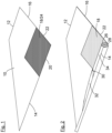
- the half-finished product of Fig. 1 comprises a pre-cut of a first fibre layer 10 lying flat on a support which is not shown.
- the pre-cut has a trapezoidal shape with two parallel edges 12, 14 extending in a length direction of the pre-cut and with a third edge 16 arranged perpendicular thereto.
- the first fibre layer 10 is a layer of unidirectional fibres extending in the length direction, that is parallel to the parallel edges 12, 14.
- a rectangular interface layer 18 On top of the pre-cut, a rectangular interface layer 18 has been positioned such that an edge corresponding to a first side 20 of the rectangle is aligned with the parallel edge 14, and an edge corresponding to a second side 22 of the rectangle is aligned with the third edge 16 of the pre-cut.
- a protective film 24 covers the upper side of the interface layer 18.
- a metal insert 26 has been placed on top of this upper surface.
- the metal insert 26 is a cylindrical sleeve made of steel and comprising a circumferential outer surface 34 and a threaded bore 28 forming a joining portion.
- a wedge-shaped core material 32 is arranged, tapering in a direction away from the metal insert 26.
- the metal insert 26 together with the wedge-shaped core material 32 is wrapped in the half-finished product.
- Fig. 2 about one third of a full rotation has been made, so that the parallel edge 14 of the pre-cut can be seen lying parallel to a longitudinal axis of the metal insert 26, closely adhering at the circumferential outer surface 34.
- Figure 3 illustrates the inventive method at a later stage, when all of the materials have been placed in a mould 36.
- the mould 36 has a mould surface 38 at which an outer surface of the wind turbine rotor blade element 40 is formed.
- three layers 42 of a second fibre material are arranged on top of the mould surface 38.
- On top of the uppermost layer 42 one can see three wrapped metal inserts, each comprising a sleeve-shaped metal insert 26 with a threaded bore 28, an interface layer 18 placed in direct contact with the circumferential outer surface 34 of the metal insert 26, and a first fibre layer 10 closely wrapped around the metal insert 66 and the interface layer 18.
- three further second fibre layers 44 are arranged.
- additional elements may be positioned in the mould 36, in particular additional fibre materials and/or core materials, for example placeholders arranged between the wrapped metal inserts. All of the materials in the mould 36 are embedded in a liquid plastics material (not shown), for example in a vacuum infusion process.
Landscapes
- Engineering & Computer Science (AREA)
- Mechanical Engineering (AREA)
- Chemical & Material Sciences (AREA)
- Composite Materials (AREA)
- Wind Motors (AREA)
- Moulding By Coating Moulds (AREA)
Description
- The invention relates to a method of manufacturing a wind turbine rotor blade element with a metal insert.
- Wind turbine rotor blades typically comprise large structures of laminated, fibre reinforced plastics. For joining these structures to other elements, it is known to anchor metal inserts in the laminated structures. For example, many wind turbine rotor blades have a root section with integrated metal inserts including threaded bores. They are joined to a wind turbine rotor hub by means of bolts guided through holes in a wind turbine rotor hub flange and screwed into the threaded bores of the metal inserts. Similar connections can be made between adjacent sections of a wind turbine rotor blade divided into two or more longitudinal sections. In this case, metal inserts can be integrated into one or both of the adjacent sections.
- Since all of these connections are subject to extreme loads, obtaining a strong bond between the metal inserts and the surrounding laminate is essential. To this end, different techniques have been suggested.
- The document
EP 2 781 344 B1 discloses a method of manufacturing a portion of a wind turbine blade using so-called pre-impregnated metal inserts. The pre-impregnated metal inserts consist of a metal insert covered with a layer of pre-impregnated fibres which is cured before the pre-impregnated metal insert is integrated in a laminated blade structure. - From the
document DE 10 2015 007 977 A1 , it has become known to place numerous steel inserts in a mould along the circumference of a wind turbine rotor blade root between inner and outer fibre layers. Before placing the steel inserts in the mould, upper and lower surfaces of the steel inserts are provided with a thin layer of silicon oxide and with a layer of an adhesive, namely an epoxy resin or a polyurethane adhesive. - From the document
EP 3 121 441 A1 a method of manufacturing a root assembly for a wind turbine rotor blade has become known. Metal inserts are arranged in a circumferential gap between inner and outer layers of a thermoplastic material. The metal inserts are also surrounded with a thermoplastic material. By applying heat, the metal inserts shall be welded to the inner and outer layers. - From the document
WO 2017/215735 A1 a method for manufacturing a connection structure of a wind turbine rotor blade has become known. Metal inserts are wrapped in a fibre layer before being placed between inner and outer fibre layers of a blade root section. Then, the entire structure is infused with a resin and cured. - From the document
EP 3 441 567 A1 a method of manufacturing a wind turbine rotor blade root section has become known. On top of fibre layers laid in a mould, a layer of an adhesive, for example a semi-cured epoxy resin, is placed. Metal inserts are arranged on top of the adhesive layer. On top of the metal inserts, another layer of an adhesive and further fibre layers are arranged. A liquid resin is infused and then cured together with the adhesive. - From the document
US 2020/0263658 A1 a method of manufacturing a wind turbine rotor blade root end structure has become known. The root end structure comprises a plurality of fastening inserts distributed along a root end of a blade part, wherein a plurality of pultruded elements are arranged in between the fastening inserts. Gaps between the pultruded elements and the fastening inserts can be filled with a fibre material wrapped around the inserts. - From the document
US 2020/0347820 A1 a method with the features of the preamble ofclaim 1 has become known. Inserts used in the method are wrapped in several layers of a dry fibre material together forming a so-called transition layer. - Starting therefrom, it is an object of the invention to provide a method of manufacturing a wind turbine rotor blade element with a metal insert, wherein the method is easy to use and delivers a consistent anchoring of a metal insert in a surrounding composite material.
- This problem is solved by the method of manufacturing a wind turbine rotor blade element with the features of
independent claim 1. Advantageous aspects of the invention are given in the dependent claims. - The method is defined in
claim 1. - The invention is based on the fact that the materials used for manufacturing of wind turbine rotor blades are not always of the same quality. When looking at the connection of a metal insert to a surrounding composite material, varying characteristics of the metal insert have been addressed by specific surface treatments, such as sand blasting or coating with silicon dioxide. The inventor realized that another important factor to be taken into account are varying characteristics of the liquid plastics material and the laminate material. Both materials are needed in large quantities, and sourcing from different chemical companies may be necessary, in particular for manufacturing sites located in different geographic regions. In some cases, small variations of the liquid plastics material have a surprisingly large effect on the bonding quality, even if the surface characteristics of the metal insert are perfectly controlled. Variations in the laminate material lead to changing stiffness in the composite material and influence the bonding strength.
- The invention overcomes these difficulties by applying an interface layer between the metal insert and the liquid plastics material. The interface layer on the one hand forms strong bonds with the metal insert surface as well as with the surrounding composite material formed by embedding fibre layers in the liquid plastics material. On the other hand, the interface layer prevents the metal insert's surface at least partly from getting into direct contact with the liquid plastics material, and therefore also has a decoupling effect. It has been found that by means of the interface layer, it is easier to consistently obtain a sufficiently strong anchoring of the metal insert in the composite material. The inventive manufacturing method for this reason helps meeting the specifications even if the quality of the liquid plastics material varies to some extent.
- The wind turbine rotor blade element may be an essentially complete wind turbine rotor blade or any part or section thereof, for example a pressure side-half shell, a suction side-half shell, a section of a wind turbine rotor blade divided into two or more longitudinal sections, or a segment or part of such a section. The wind turbine rotor blade element may extend over the entire length of the wind turbine rotor blade (from a wind turbine rotor blade root to a wind turbine rotor blade tip), or only over a section of this length. This section may include either the wind turbine rotor blade root or the wind turbine rotor blade tip or none of them. The wind turbine rotor blade element may comprise an outer surface that forms an aerodynamic surface of the wind turbine rotor blade, for example if the wind turbine rotor blade element is a wind turbine rotor blade half shell. In the alternative, the wind turbine rotor blade element may be an inner reinforcing member of a wind turbine rotor blade, such as a spar or spar cap or a longitudinal section thereof, or a ring-shaped or ring-section-shaped reinforcing member to be integrated into a wind turbine rotor blade root or adjacent to a segmentation plane of a wind turbine rotor blade divided into two or more longitudinal sections.
- The metal insert may have a generally cylindrical shape. It may be a sleeve comprising, as the joining portion, a threaded bore, or a bolt comprising, as the joining portion, an outer thread. The circumferential outer surface may be cylindrical, however, it may also have a varying diameter, for example comprising a conical shape. The longitudinal axis of the metal insert may be aligned with a longitudinal direction of the wind turbine rotor blade element and/or a longitudinal direction of the wind turbine rotor blade for which the wind turbine rotor blade element is used. Of course, the wind turbine rotor blade element may include any number of metal inserts, for example arranged side-by-side and/or with parallel longitudinal axes. The metal insert may consist of any suitable metal, in particular of steel or aluminium or an alloy of these and/or other metals.
- After having wrapped the metal insert in the interface layer and in the first fibre layer, the interface layer is arranged between the circumferential outer surface of the metal insert and the first fibre layer, so that one side of the interface layer is in contact with the circumferential outer surface and the other side of the interface layer is in contact with the first fibre layer. As has been explained above, the interface layer therefore can perform its double function of forming a strong bond between the metal insert and the surrounding composite material, and of "decoupling" the metal insert from the liquid plastics material.
- The interface layer can be handled as a layer, so that it can be wrapped around the metal insert, either alone or in combination with the first fibre layer (see below). This requires a certain level of rigidity of the interface layer and excludes liquid materials having a low viscosity, such as liquid plastics materials commonly used for impregnating fibre materials processed by hand lay-up or applied by resin infusion. However, the interface layer is a curable material that, before it has been cured, can easily be plastically deformed so that it can be wrapped around the metal insert.
- The interface layer in general prevents the liquid plastics material from contacting the circumferential outer surface directly, so the interface layer forms a closed layer which is substantially impermeable for the liquid plastics material. However, when wrapping the metal insert in the interface layer and the first fibre layer, some fibres of the first fibre layer may be pressed partly or fully into the interface layer.
- The first fibre layer and the second fibre layers may comprise any suitable reinforcing fibres, such as glass or carbon fibres, etc. The first fibre layer and the second fibre layer may comprise the same type or different types of reinforcing fibres. The first fibre layer and/or the second fibre layers may be placed in the mould in dry form. However, it is also possible to use a combination of dry fibre layers and pre-impregnated fibre layers.
- The step of embedding the plurality of second fibre layers and the wrapped metal insert in a liquid plastics material may be carried out with any suitable technique, in particular by means of vacuum infusion. The liquid plastics material will penetrate the second fibre layers and any other dry fibre materials present in the mould, possibly including the first fibre layer. The liquid plastics material and the interface layer will be cured together in the mould, if desired by applying heat (tempering).
- According to an aspect, in a first step, before wrapping the metal insert, a flat, half-finished product is formed which comprises the interface layer and the first fibre layer, wherein the half-finished product in a second step is wrapped around the metal insert. By combining the interface layer and the first fibre layer to a half-finished product, wrapping the metal insert in these two layers can be carried out in a single process. Moreover, combining both layers before carrying out the wrapping process can make it easier to position the interface layer relative to the first fibre layer exactly as desired.
- According to an aspect, forming the half-finished product comprises placing the interface layer on top of the first fibre layer. This can be done in particular on a flat support such as a work table. It is then particularly easy to position the metal insert with reference to the interface layer.
- According to an aspect, forming the half-finished product comprises pressing the interface layer on the first fibre layer, while an upper side of the interface layer is covered with a protective film. Pressing can be done for example with a roller rolled over the protective film. Some fibres of the first fibre layer may be pressed into the interface layer. Pressing the interface layer on the first fibre layer ensures a direct contact between the interface layer and the first fibre layer, so that when embedding the wrapped insert in the liquid plastics material, there will be no dead volumes between the two layers which could otherwise be filled with liquid plastics material.
- According to an aspect, the protective film is removed before or during the second step. In particular, the protective film may remain on the interface layer just until the metal insert is wrapped therein. The upper surface of the interface layer then is in optimal condition for making contact to the circumferential outer surface of the metal insert.
- According to an aspect, wrapping the half-finished product around the metal insert comprises placing the half-finished product on a flat support, placing the metal insert on the half-finished product and rolling the metal insert around its longitudinal axis. By rolling the metal insert on the flat support, a suitable compression force can be applied so that the interface layer will be arranged in direct contact with the circumferential outer surface, and the half-finished product will form a tight-fitting sheath surrounding the metal insert.
- According to an aspect, the interface layer is a layer of an adhesive material comprising the same type of polymers as the liquid plastics material. For example, both materials may be based on polyester or epoxy resin. The interface layer may have a chemical formulation such that is almost rigid at room temperature, while the liquid plastics material then has a low viscosity.
- According to an aspect, the first fibre layer is a layer of unidirectional fibres which are aligned with the longitudinal axis of the metal insert when the first fibre layer has been wrapped around the metal insert. This is ideal for transferring loads acting in the longitudinal direction from the metal insert to the surrounding composite material, and vice versa.
- According to an aspect, the first fibre layer is provided as a pre-cut having a width and a length, wherein the length is larger than a length of the metal insert and the width is larger than a circumference of the circumferential outer surface of the metal insert. The first fibre layer can then form at least one turn, preferably more than one turn, such as 2 to 8 turns, around the metal insert, and can cover the entire length of the metal insert.
- According to an aspect, the pre-cut has the shape of a trapezoid, with two parallel edges aligned with the length direction of the pre-cut and a third edge arranged substantially perpendicular to the length direction, wherein one of the parallel edges has a length corresponding to the length of the metal insert, and the other one of the parallel edges is at least twice as long. By means of this shape, the wrapped metal insert will taper towards a distal end. This facilitates a smooth integration of the wrapped metal insert in the surrounding composite material.
- According to an aspect, the interface layer has the shape of a rectangle, with a first side being as long as the metal insert and a second side having a width corresponding to a circumference of the circumferential outer surface of the metal insert. This ensures the interface layer will cover the entire circumferential outer surface. It is also possible to make the interface layer slightly larger, in particular in the width direction, so that it will form more than exactly one turn, overlapping the first fibre layer in a longitudinally oriented strip.
- According to an aspect, when forming the half-finished product, the first side of the interface layer is aligned with the longer one of the two parallel edges of the pre-cut. The metal insert can then be wrapped in the half-finished product starting at the longer one of the parallel edges, thereby forming a helical structure.
- According to an aspect, the longitudinal axis of the metal insert is arranged parallel to a longitudinal axis of the wind turbine rotor blade element. This is most suitable for transferring the respective loads.
- According to an aspect, the interface layer has a weight in the range of 40 g/m2 to 240 g/m2 and/or the first fibre layer has a weight in the range of 400 g/m2 to 2400 g/m2. This means the interface layer is relatively thin.
- According to an aspect, a wedge-shaped core material is arranged at a distal end of the metal insert and wrapped in the first fibre layer together with the metal insert. This leads to a tapering thickness of the wrapped insert and to a smooth integration in the surrounding composite material.
- In the following, the invention is explained in greater detailed based on an embodiment shown in drawings. The figures show:
- Fig. 1
- a half-finished product in a schematic, perspective view;
- Fig. 2
- an illustration of the step of wrapping a metal insert in the half-finished product of
Fig. 1 in a schematic, perspective view; and - Fig. 3
- a wind turbine rotor blade element schematically shown in cross section.
- The half-finished product of
Fig. 1 comprises a pre-cut of afirst fibre layer 10 lying flat on a support which is not shown. The pre-cut has a trapezoidal shape with twoparallel edges third edge 16 arranged perpendicular thereto. Thefirst fibre layer 10 is a layer of unidirectional fibres extending in the length direction, that is parallel to theparallel edges - On top of the pre-cut, a
rectangular interface layer 18 has been positioned such that an edge corresponding to afirst side 20 of the rectangle is aligned with theparallel edge 14, and an edge corresponding to asecond side 22 of the rectangle is aligned with thethird edge 16 of the pre-cut. InFig. 1 , a protective film 24 covers the upper side of theinterface layer 18. - In
Fig. 2 , the protective film 24 has been removed, so that the upper side of theinterface layer 18 can be seen. On top of this upper surface, ametal insert 26 has been placed. Themetal insert 26 is a cylindrical sleeve made of steel and comprising a circumferentialouter surface 34 and a threadedbore 28 forming a joining portion. At adistal end 30 of themetal insert 26, a wedge-shapedcore material 32 is arranged, tapering in a direction away from themetal insert 26. - The
metal insert 26 together with the wedge-shapedcore material 32 is wrapped in the half-finished product. InFig. 2 , about one third of a full rotation has been made, so that theparallel edge 14 of the pre-cut can be seen lying parallel to a longitudinal axis of themetal insert 26, closely adhering at the circumferentialouter surface 34. -
Figure 3 illustrates the inventive method at a later stage, when all of the materials have been placed in amould 36. Themould 36 has amould surface 38 at which an outer surface of the wind turbinerotor blade element 40 is formed. On top of themould surface 38, threelayers 42 of a second fibre material are arranged. On top of theuppermost layer 42 one can see three wrapped metal inserts, each comprising a sleeve-shapedmetal insert 26 with a threadedbore 28, aninterface layer 18 placed in direct contact with the circumferentialouter surface 34 of themetal insert 26, and afirst fibre layer 10 closely wrapped around the metal insert 66 and theinterface layer 18. - On top of the wrapped metal inserts, three further second fibre layers 44 are arranged. Although not shown, it is understood that additional elements may be positioned in the
mould 36, in particular additional fibre materials and/or core materials, for example placeholders arranged between the wrapped metal inserts. All of the materials in themould 36 are embedded in a liquid plastics material (not shown), for example in a vacuum infusion process. -
- 10
- first fibre layer
- 12
- parallel edge of
first fibre layer 10 - 14
- parallel edge of
first fibre layer 10 - 16
- third edge of
first fibre layer 10 - 18
- interface layer
- 20
- first side
- 22
- second side
- 24
- protective film
- 26
- metal insert
- 28
- threaded bore
- 30
- distal end of metal insert
- 32
- wedge-shaped core material
- 34
- circumferential outer surface
- 36
- mould
- 38
- mould surface
- 40
- wind turbine rotor blade element
- 42
- second fibre layer
- 44
- second fibre layer
Claims (15)
- A method of manufacturing a wind turbine rotor blade element (40), the method comprising the following steps:• providing a metal insert (26) having a longitudinal axis, a circumferential outer surface (34) and a joining portion for connecting the wind turbine rotor blade element (40) to a wind turbine rotor hub or to another wind turbine rotor blade element,• wrapping the metal insert (26) in a first fibre layer (10),• positioning the wrapped metal insert in a mould (36),• arranging a plurality of second fibre layers (42, 44) in the mould (36),• embedding the plurality of second fibre layers (42, 44) and the wrapped metal insert in a liquid plastics material,• curing the liquid plastics material in the mould, characterized by the following steps:• wrapping the metal insert (26) in an interface layer (18) of a curable material such that the interface layer (18) is arranged between the circumferential outer surface (34) and the first fibre layer (10), wherein the entire circumferential outer surface (34) is covered by the interface layer (18) which forms a closed layer substantially impermeable for the liquid plastics material, and• curing the interface layer (18) in the mould together with the liquid plastics material.
- The method of claim 1, characterised in that in a first step, before wrapping the metal insert (26), a flat, half-finished product is formed which comprises the interface layer (18) and the first fibre layer (10), wherein the half-finished product in a second step is wrapped around the metal insert (26).
- The method of claim 2, characterised in that forming the half-finished product comprises placing the interface layer (18) on top of the first fibre layer (10).
- The method of claim 3, characterised in that forming the half-finished product comprises pressing the interface layer (18) on the first fibre layer (10), while an upper side of the interface layer (18) is covered with a protective film (24).
- The method of claim 4, characterised in that the protective film (24) is removed before or during the second step.
- The method of any of claims 2 to 4, characterised in that wrapping the half-finished product around the metal insert (26) comprises placing the half-finished product on a flat support, placing the metal insert (26) on the half-finished product and rolling the metal insert (26) around its longitudinal axis.
- The method of any of the claims 1 to 6, characterised in that the interface layer (18) is a layer of an adhesive material comprising the same type of polymers as the liquid plastics material.
- The method of any of the claims 1 to 7, characterised in that the first fibre layer (10) is a layer of unidirectional fibres which are aligned with the longitudinal axis of the metal insert (26) when the first fibre layer (10) has been wrapped around the metal insert (26).
- The method of any of the claims 1 to 8, characterised in that the first fibre layer (10) is provided as a pre-cut having a width and a length, wherein the length is larger than a length of the metal insert (26) and the width is larger than a circumference of the circumferential outer surface (34) of the metal insert (26).
- The method of claim 9, characterised in that the pre-cut has the shape of a trapezoid, with two parallel edges (12, 14) aligned with the length direction of the pre-cut and a third edge (16) arranged substantially perpendicular to the length direction, wherein one of the parallel edges (12) has a length corresponding to the length of the metal insert (26), and the other one of the parallel edges (14) is at least twice as long.
- The method of any of the claims 1 to 10, characterised in that the interface layer (18) has the shape of a rectangle, with a first side (20) being as long as the metal insert (26) and a second side (22) having a width corresponding to a circumference of the circumferential outer surface (34) of the metal insert (26).
- The method of claim 11, characterised in that when forming the half-finished product, the first side (20) is aligned with the longer one of the two parallel edges (12, 14) of the pre-cut.
- The method of any of the claims 1 to 12, characterised in that the longitudinal axis of the metal insert (26) is arranged parallel to a longitudinal axis of the wind turbine rotor blade element (40).
- The method of any of the claims 1 to 13, characterised in that the interface layer (18) has a weight in the range of 40 g/m2 to 240 g/m2 and/or in that the first fibre layer (10) has a weight in the range of 400 g/m2 to 2400 g/m2.
- The method of any of the claims 1 to 14, characterised in that a wedge-shaped core material (32) is arranged at a distal end (30) of the metal insert (26) and wrapped in the first fibre layer (10) together with the metal insert (26).
Priority Applications (4)
| Application Number | Priority Date | Filing Date | Title |
|---|---|---|---|
| EP21155026.4A EP4039436B1 (en) | 2021-02-03 | 2021-02-03 | A method of manufacturing a wind turbine rotor blade element with a metal insert |
| PT211550264T PT4039436T (en) | 2021-02-03 | 2021-02-03 | METHOD OF MANUFACTURING A WIND TURBINE ROTOR BLADE ELEMENT WITH A METAL INSERT |
| ES21155026T ES3036935T3 (en) | 2021-02-03 | 2021-02-03 | A method of manufacturing a wind turbine rotor blade element with a metal insert |
| DK21155026.4T DK4039436T3 (en) | 2021-02-03 | 2021-02-03 | METHOD FOR MANUFACTURING A WIND MILL ROTOR BLADE ELEMENT WITH A METAL INSERT |
Applications Claiming Priority (1)
| Application Number | Priority Date | Filing Date | Title |
|---|---|---|---|
| EP21155026.4A EP4039436B1 (en) | 2021-02-03 | 2021-02-03 | A method of manufacturing a wind turbine rotor blade element with a metal insert |
Publications (2)
| Publication Number | Publication Date |
|---|---|
| EP4039436A1 EP4039436A1 (en) | 2022-08-10 |
| EP4039436B1 true EP4039436B1 (en) | 2025-06-18 |
Family
ID=74550552
Family Applications (1)
| Application Number | Title | Priority Date | Filing Date |
|---|---|---|---|
| EP21155026.4A Active EP4039436B1 (en) | 2021-02-03 | 2021-02-03 | A method of manufacturing a wind turbine rotor blade element with a metal insert |
Country Status (4)
| Country | Link |
|---|---|
| EP (1) | EP4039436B1 (en) |
| DK (1) | DK4039436T3 (en) |
| ES (1) | ES3036935T3 (en) |
| PT (1) | PT4039436T (en) |
Families Citing this family (1)
| Publication number | Priority date | Publication date | Assignee | Title |
|---|---|---|---|---|
| EP4660447A1 (en) * | 2024-06-05 | 2025-12-10 | LM Wind Power A/S | Methods and assemblies for installing bushings in the root of a wind turbine blade |
Family Cites Families (9)
| Publication number | Priority date | Publication date | Assignee | Title |
|---|---|---|---|---|
| US5281454A (en) * | 1991-08-16 | 1994-01-25 | Kaiser Aerospace & Electronics Corporation | Closed composite sections with bonded scarf joints |
| EP2781344B1 (en) | 2013-03-21 | 2019-10-09 | GE Renewable Technologies Wind B.V. | Method of manufacturing a portion of a wind turbine blade |
| DE102015007977A1 (en) | 2015-06-23 | 2016-12-29 | Senvion Gmbh | Rotor blade connection with steel laminate bonding |
| US9970304B2 (en) | 2015-07-22 | 2018-05-15 | General Electric Company | Rotor blade root assembly for a wind turbine |
| DK3468781T3 (en) | 2016-06-14 | 2022-10-24 | Nordex Blade Tech Centre Aps | Connection structure for a wind turbine blade and method of manufacturing it |
| GB201712722D0 (en) | 2017-08-08 | 2017-09-20 | Dfs Composites Ltd | Method of manufacturing a wind turbine blade root prefab, and a wind turbine blade root prefab |
| EP3697603B1 (en) * | 2017-10-18 | 2024-08-28 | LM Wind Power A/S | A wind turbine blade comprising a root end structure with an adaptive positioning of the pultruded element |
| EP3721076B1 (en) * | 2017-12-08 | 2022-12-07 | Vestas Wind Systems A/S | Insert for a wind turbine blade root |
| GB2569297A (en) * | 2017-12-08 | 2019-06-19 | Vestas Wind Sys As | Wind turbine blade root bushing replacement method and insert |
-
2021
- 2021-02-03 PT PT211550264T patent/PT4039436T/en unknown
- 2021-02-03 EP EP21155026.4A patent/EP4039436B1/en active Active
- 2021-02-03 ES ES21155026T patent/ES3036935T3/en active Active
- 2021-02-03 DK DK21155026.4T patent/DK4039436T3/en active
Also Published As
| Publication number | Publication date |
|---|---|
| EP4039436A1 (en) | 2022-08-10 |
| DK4039436T3 (en) | 2025-08-18 |
| PT4039436T (en) | 2025-08-05 |
| ES3036935T3 (en) | 2025-09-25 |
Similar Documents
| Publication | Publication Date | Title |
|---|---|---|
| EP2922690B1 (en) | Wind turbine blades and method of manufacturing the same | |
| EP2349703B1 (en) | An insert and method for forming an end connection in a uni-axial composite material | |
| EP3212387B1 (en) | Manufacture of i-shaped shear web, method and apparatus | |
| EP3721076B1 (en) | Insert for a wind turbine blade root | |
| EP3099477B1 (en) | Wind turbine blade with improved fibre transition | |
| EP3475068B1 (en) | Manufacture of a wind turbine blade | |
| EP3099471B1 (en) | Method for manufacturing a wind turbine blade part in two steps | |
| EP2318197B1 (en) | A method of manufacturing a spar for a wind turbine from elements having geometrically well-defined joint surface portions, and the related spar | |
| EP3441567A1 (en) | Method of manufacturing a wind turbine blade root prefab, and a wind turbine blade root prefab | |
| EP2318705B1 (en) | A method of manufacturing a spar for a wind turbine from elements comprising different materials, and the related spar | |
| US8899936B2 (en) | Method of manufacturing a spar for a wind turbine from elements having end portions extending transversely to an intermediate portion | |
| CA2951738C (en) | A method of producing a continuous fibre reinforcement layer from individual fibre mats | |
| WO2012140039A2 (en) | Wind turbine blade comprising circumferential retaining means in root regions | |
| EP4000877A1 (en) | A method for producing a rotor blade of a wind turbine | |
| WO2009153344A1 (en) | An assembly tool for a spar for a wind turbine | |
| EP3708825B1 (en) | Wind turbine blade and method for producing a wind turbine blade | |
| EP3468781B1 (en) | A connection structure of a wind turbine blade and method for its manufacture | |
| EP4039436A1 (en) | A method of manufacturing a wind turbine rotor blade element with a metal insert | |
| US12540597B2 (en) | Spar cap with tapering and serrated end section | |
| EP4092261B1 (en) | A wind turbine rotor blade element with connection assemblies | |
| CN114729621B (en) | A root bushing, a bushing insert thereof, a wind turbine blade including the root bushing and a manufacturing method thereof | |
| WO2015144383A1 (en) | Turbine blade and method of manufacture | |
| EP4438887A1 (en) | Laminate structure for a flange connection of a wind turbine rotor blade, connecting element, wind turbine rotor blade and method for manufacturing a laminate structure |
Legal Events
| Date | Code | Title | Description |
|---|---|---|---|
| PUAI | Public reference made under article 153(3) epc to a published international application that has entered the european phase |
Free format text: ORIGINAL CODE: 0009012 |
|
| STAA | Information on the status of an ep patent application or granted ep patent |
Free format text: STATUS: THE APPLICATION HAS BEEN PUBLISHED |
|
| AK | Designated contracting states |
Kind code of ref document: A1 Designated state(s): AL AT BE BG CH CY CZ DE DK EE ES FI FR GB GR HR HU IE IS IT LI LT LU LV MC MK MT NL NO PL PT RO RS SE SI SK SM TR |
|
| STAA | Information on the status of an ep patent application or granted ep patent |
Free format text: STATUS: REQUEST FOR EXAMINATION WAS MADE |
|
| 17P | Request for examination filed |
Effective date: 20230113 |
|
| RBV | Designated contracting states (corrected) |
Designated state(s): AL AT BE BG CH CY CZ DE DK EE ES FI FR GB GR HR HU IE IS IT LI LT LU LV MC MK MT NL NO PL PT RO RS SE SI SK SM TR |
|
| GRAP | Despatch of communication of intention to grant a patent |
Free format text: ORIGINAL CODE: EPIDOSNIGR1 |
|
| STAA | Information on the status of an ep patent application or granted ep patent |
Free format text: STATUS: GRANT OF PATENT IS INTENDED |
|
| RIC1 | Information provided on ipc code assigned before grant |
Ipc: B29L 31/00 20060101ALN20250115BHEP Ipc: B29L 31/08 20060101ALN20250115BHEP Ipc: B29C 70/32 20060101ALI20250115BHEP Ipc: B29C 70/84 20060101ALI20250115BHEP Ipc: F03D 1/06 20060101ALI20250115BHEP Ipc: B29C 70/86 20060101ALI20250115BHEP Ipc: B29C 70/44 20060101ALI20250115BHEP Ipc: B29D 99/00 20100101ALI20250115BHEP Ipc: B29C 37/00 20060101AFI20250115BHEP |
|
| INTG | Intention to grant announced |
Effective date: 20250123 |
|
| GRAS | Grant fee paid |
Free format text: ORIGINAL CODE: EPIDOSNIGR3 |
|
| GRAA | (expected) grant |
Free format text: ORIGINAL CODE: 0009210 |
|
| STAA | Information on the status of an ep patent application or granted ep patent |
Free format text: STATUS: THE PATENT HAS BEEN GRANTED |
|
| AK | Designated contracting states |
Kind code of ref document: B1 Designated state(s): AL AT BE BG CH CY CZ DE DK EE ES FI FR GB GR HR HU IE IS IT LI LT LU LV MC MK MT NL NO PL PT RO RS SE SI SK SM TR |
|
| REG | Reference to a national code |
Ref country code: GB Ref legal event code: FG4D |
|
| REG | Reference to a national code |
Ref country code: CH Ref legal event code: EP |
|
| REG | Reference to a national code |
Ref country code: DE Ref legal event code: R096 Ref document number: 602021032317 Country of ref document: DE |
|
| REG | Reference to a national code |
Ref country code: CH Ref legal event code: EP |
|
| REG | Reference to a national code |
Ref country code: IE Ref legal event code: FG4D |
|
| REG | Reference to a national code |
Ref country code: PT Ref legal event code: SC4A Ref document number: 4039436 Country of ref document: PT Date of ref document: 20250805 Kind code of ref document: T Free format text: AVAILABILITY OF NATIONAL TRANSLATION Effective date: 20250731 |
|
| REG | Reference to a national code |
Ref country code: DK Ref legal event code: T3 Effective date: 20250806 |
|
| REG | Reference to a national code |
Ref country code: ES Ref legal event code: FG2A Ref document number: 3036935 Country of ref document: ES Kind code of ref document: T3 Effective date: 20250925 |
|
| PG25 | Lapsed in a contracting state [announced via postgrant information from national office to epo] |
Ref country code: FI Free format text: LAPSE BECAUSE OF FAILURE TO SUBMIT A TRANSLATION OF THE DESCRIPTION OR TO PAY THE FEE WITHIN THE PRESCRIBED TIME-LIMIT Effective date: 20250618 |
|
| REG | Reference to a national code |
Ref country code: LT Ref legal event code: MG9D |
|
| PG25 | Lapsed in a contracting state [announced via postgrant information from national office to epo] |
Ref country code: NO Free format text: LAPSE BECAUSE OF FAILURE TO SUBMIT A TRANSLATION OF THE DESCRIPTION OR TO PAY THE FEE WITHIN THE PRESCRIBED TIME-LIMIT Effective date: 20250918 Ref country code: GR Free format text: LAPSE BECAUSE OF FAILURE TO SUBMIT A TRANSLATION OF THE DESCRIPTION OR TO PAY THE FEE WITHIN THE PRESCRIBED TIME-LIMIT Effective date: 20250919 |
|
| PG25 | Lapsed in a contracting state [announced via postgrant information from national office to epo] |
Ref country code: BG Free format text: LAPSE BECAUSE OF FAILURE TO SUBMIT A TRANSLATION OF THE DESCRIPTION OR TO PAY THE FEE WITHIN THE PRESCRIBED TIME-LIMIT Effective date: 20250618 |
|
| PG25 | Lapsed in a contracting state [announced via postgrant information from national office to epo] |
Ref country code: HR Free format text: LAPSE BECAUSE OF FAILURE TO SUBMIT A TRANSLATION OF THE DESCRIPTION OR TO PAY THE FEE WITHIN THE PRESCRIBED TIME-LIMIT Effective date: 20250618 |
|
| PG25 | Lapsed in a contracting state [announced via postgrant information from national office to epo] |
Ref country code: RS Free format text: LAPSE BECAUSE OF FAILURE TO SUBMIT A TRANSLATION OF THE DESCRIPTION OR TO PAY THE FEE WITHIN THE PRESCRIBED TIME-LIMIT Effective date: 20250918 |
|
| REG | Reference to a national code |
Ref country code: NL Ref legal event code: MP Effective date: 20250618 |
|
| PG25 | Lapsed in a contracting state [announced via postgrant information from national office to epo] |
Ref country code: LV Free format text: LAPSE BECAUSE OF FAILURE TO SUBMIT A TRANSLATION OF THE DESCRIPTION OR TO PAY THE FEE WITHIN THE PRESCRIBED TIME-LIMIT Effective date: 20250618 |
|
| PG25 | Lapsed in a contracting state [announced via postgrant information from national office to epo] |
Ref country code: NL Free format text: LAPSE BECAUSE OF FAILURE TO SUBMIT A TRANSLATION OF THE DESCRIPTION OR TO PAY THE FEE WITHIN THE PRESCRIBED TIME-LIMIT Effective date: 20250618 |
|
| REG | Reference to a national code |
Ref country code: AT Ref legal event code: MK05 Ref document number: 1803828 Country of ref document: AT Kind code of ref document: T Effective date: 20250618 |
|
| PG25 | Lapsed in a contracting state [announced via postgrant information from national office to epo] |
Ref country code: IS Free format text: LAPSE BECAUSE OF FAILURE TO SUBMIT A TRANSLATION OF THE DESCRIPTION OR TO PAY THE FEE WITHIN THE PRESCRIBED TIME-LIMIT Effective date: 20251018 |
|
| PG25 | Lapsed in a contracting state [announced via postgrant information from national office to epo] |
Ref country code: AT Free format text: LAPSE BECAUSE OF FAILURE TO SUBMIT A TRANSLATION OF THE DESCRIPTION OR TO PAY THE FEE WITHIN THE PRESCRIBED TIME-LIMIT Effective date: 20250618 Ref country code: SM Free format text: LAPSE BECAUSE OF FAILURE TO SUBMIT A TRANSLATION OF THE DESCRIPTION OR TO PAY THE FEE WITHIN THE PRESCRIBED TIME-LIMIT Effective date: 20250618 |
|
| PG25 | Lapsed in a contracting state [announced via postgrant information from national office to epo] |
Ref country code: CZ Free format text: LAPSE BECAUSE OF FAILURE TO SUBMIT A TRANSLATION OF THE DESCRIPTION OR TO PAY THE FEE WITHIN THE PRESCRIBED TIME-LIMIT Effective date: 20250618 |
|
| PG25 | Lapsed in a contracting state [announced via postgrant information from national office to epo] |
Ref country code: PL Free format text: LAPSE BECAUSE OF FAILURE TO SUBMIT A TRANSLATION OF THE DESCRIPTION OR TO PAY THE FEE WITHIN THE PRESCRIBED TIME-LIMIT Effective date: 20250618 |
|
| PG25 | Lapsed in a contracting state [announced via postgrant information from national office to epo] |
Ref country code: EE Free format text: LAPSE BECAUSE OF FAILURE TO SUBMIT A TRANSLATION OF THE DESCRIPTION OR TO PAY THE FEE WITHIN THE PRESCRIBED TIME-LIMIT Effective date: 20250618 |
|
| PG25 | Lapsed in a contracting state [announced via postgrant information from national office to epo] |
Ref country code: SK Free format text: LAPSE BECAUSE OF FAILURE TO SUBMIT A TRANSLATION OF THE DESCRIPTION OR TO PAY THE FEE WITHIN THE PRESCRIBED TIME-LIMIT Effective date: 20250618 |
|
| REG | Reference to a national code |
Ref country code: DE Ref legal event code: R097 Ref document number: 602021032317 Country of ref document: DE |
|
| PGFP | Annual fee paid to national office [announced via postgrant information from national office to epo] |
Ref country code: ES Payment date: 20260319 Year of fee payment: 6 |
|
| PGFP | Annual fee paid to national office [announced via postgrant information from national office to epo] |
Ref country code: DK Payment date: 20260217 Year of fee payment: 6 Ref country code: DE Payment date: 20260217 Year of fee payment: 6 |
|
| PG25 | Lapsed in a contracting state [announced via postgrant information from national office to epo] |
Ref country code: IT Free format text: LAPSE BECAUSE OF FAILURE TO SUBMIT A TRANSLATION OF THE DESCRIPTION OR TO PAY THE FEE WITHIN THE PRESCRIBED TIME-LIMIT Effective date: 20250618 |
|
| PGFP | Annual fee paid to national office [announced via postgrant information from national office to epo] |
Ref country code: TR Payment date: 20260129 Year of fee payment: 6 |
|
| PGFP | Annual fee paid to national office [announced via postgrant information from national office to epo] |
Ref country code: PT Payment date: 20260129 Year of fee payment: 6 |
|
| PLBE | No opposition filed within time limit |
Free format text: ORIGINAL CODE: 0009261 |
|
| STAA | Information on the status of an ep patent application or granted ep patent |
Free format text: STATUS: NO OPPOSITION FILED WITHIN TIME LIMIT |
|
| REG | Reference to a national code |
Ref country code: CH Ref legal event code: L10 Free format text: ST27 STATUS EVENT CODE: U-0-0-L10-L00 (AS PROVIDED BY THE NATIONAL OFFICE) Effective date: 20260430 |