EP4039346A1 - Variable vehicle ride switch - Google Patents
Variable vehicle ride switch Download PDFInfo
- Publication number
- EP4039346A1 EP4039346A1 EP22159786.7A EP22159786A EP4039346A1 EP 4039346 A1 EP4039346 A1 EP 4039346A1 EP 22159786 A EP22159786 A EP 22159786A EP 4039346 A1 EP4039346 A1 EP 4039346A1
- Authority
- EP
- European Patent Office
- Prior art keywords
- ride
- vehicle
- base
- conveyor
- switch
- Prior art date
- Legal status (The legal status is an assumption and is not a legal conclusion. Google has not performed a legal analysis and makes no representation as to the accuracy of the status listed.)
- Granted
Links
Images




Classifications
-
- A—HUMAN NECESSITIES
- A63—SPORTS; GAMES; AMUSEMENTS
- A63G—MERRY-GO-ROUNDS; SWINGS; ROCKING-HORSES; CHUTES; SWITCHBACKS; SIMILAR DEVICES FOR PUBLIC AMUSEMENT
- A63G1/00—Roundabouts
-
- A—HUMAN NECESSITIES
- A63—SPORTS; GAMES; AMUSEMENTS
- A63G—MERRY-GO-ROUNDS; SWINGS; ROCKING-HORSES; CHUTES; SWITCHBACKS; SIMILAR DEVICES FOR PUBLIC AMUSEMENT
- A63G1/00—Roundabouts
- A63G1/12—Roundabouts rotated by the passengers themselves
-
- A—HUMAN NECESSITIES
- A63—SPORTS; GAMES; AMUSEMENTS
- A63G—MERRY-GO-ROUNDS; SWINGS; ROCKING-HORSES; CHUTES; SWITCHBACKS; SIMILAR DEVICES FOR PUBLIC AMUSEMENT
- A63G1/00—Roundabouts
- A63G1/24—Roundabouts with seats performing movements in a horizontal plane, other than circular movements
-
- A—HUMAN NECESSITIES
- A63—SPORTS; GAMES; AMUSEMENTS
- A63G—MERRY-GO-ROUNDS; SWINGS; ROCKING-HORSES; CHUTES; SWITCHBACKS; SIMILAR DEVICES FOR PUBLIC AMUSEMENT
- A63G1/00—Roundabouts
- A63G1/48—Roundabouts with turntables and movably-mounted vehicles thereon which move to the outside when the roundabout is rotated
-
- A—HUMAN NECESSITIES
- A63—SPORTS; GAMES; AMUSEMENTS
- A63G—MERRY-GO-ROUNDS; SWINGS; ROCKING-HORSES; CHUTES; SWITCHBACKS; SIMILAR DEVICES FOR PUBLIC AMUSEMENT
- A63G21/00—Chutes; Helter-skelters
- A63G21/14—Chutes; Helter-skelters with driven slideways
-
- A—HUMAN NECESSITIES
- A63—SPORTS; GAMES; AMUSEMENTS
- A63G—MERRY-GO-ROUNDS; SWINGS; ROCKING-HORSES; CHUTES; SWITCHBACKS; SIMILAR DEVICES FOR PUBLIC AMUSEMENT
- A63G21/00—Chutes; Helter-skelters
- A63G21/18—Water-chutes
-
- A—HUMAN NECESSITIES
- A63—SPORTS; GAMES; AMUSEMENTS
- A63G—MERRY-GO-ROUNDS; SWINGS; ROCKING-HORSES; CHUTES; SWITCHBACKS; SIMILAR DEVICES FOR PUBLIC AMUSEMENT
- A63G3/00—Water roundabouts, e.g. freely floating
-
- A—HUMAN NECESSITIES
- A63—SPORTS; GAMES; AMUSEMENTS
- A63G—MERRY-GO-ROUNDS; SWINGS; ROCKING-HORSES; CHUTES; SWITCHBACKS; SIMILAR DEVICES FOR PUBLIC AMUSEMENT
- A63G3/00—Water roundabouts, e.g. freely floating
- A63G3/02—Water roundabouts, e.g. freely floating with floating seats
-
- A—HUMAN NECESSITIES
- A63—SPORTS; GAMES; AMUSEMENTS
- A63G—MERRY-GO-ROUNDS; SWINGS; ROCKING-HORSES; CHUTES; SWITCHBACKS; SIMILAR DEVICES FOR PUBLIC AMUSEMENT
- A63G31/00—Amusement arrangements
-
- A—HUMAN NECESSITIES
- A63—SPORTS; GAMES; AMUSEMENTS
- A63G—MERRY-GO-ROUNDS; SWINGS; ROCKING-HORSES; CHUTES; SWITCHBACKS; SIMILAR DEVICES FOR PUBLIC AMUSEMENT
- A63G31/00—Amusement arrangements
- A63G31/007—Amusement arrangements involving water
-
- A—HUMAN NECESSITIES
- A63—SPORTS; GAMES; AMUSEMENTS
- A63G—MERRY-GO-ROUNDS; SWINGS; ROCKING-HORSES; CHUTES; SWITCHBACKS; SIMILAR DEVICES FOR PUBLIC AMUSEMENT
- A63G4/00—Accessories for roundabouts not restricted to one of groups A63G1/00 or A63G3/00
-
- B—PERFORMING OPERATIONS; TRANSPORTING
- B65—CONVEYING; PACKING; STORING; HANDLING THIN OR FILAMENTARY MATERIAL
- B65G—TRANSPORT OR STORAGE DEVICES, e.g. CONVEYORS FOR LOADING OR TIPPING, SHOP CONVEYOR SYSTEMS OR PNEUMATIC TUBE CONVEYORS
- B65G47/00—Article or material-handling devices associated with conveyors; Methods employing such devices
- B65G47/34—Devices for discharging articles or materials from conveyor
- B65G47/46—Devices for discharging articles or materials from conveyor and distributing, e.g. automatically, to desired points
- B65G47/48—Devices for discharging articles or materials from conveyor and distributing, e.g. automatically, to desired points according to bodily destination marks on either articles or load-carriers
- B65G47/485—Devices for discharging articles or materials from conveyor and distributing, e.g. automatically, to desired points according to bodily destination marks on either articles or load-carriers using electric or electronic transmitting means between destination marks and switching means
- B65G47/487—Devices for discharging articles or materials from conveyor and distributing, e.g. automatically, to desired points according to bodily destination marks on either articles or load-carriers using electric or electronic transmitting means between destination marks and switching means the destination marks being mechanically detected
-
- A—HUMAN NECESSITIES
- A63—SPORTS; GAMES; AMUSEMENTS
- A63G—MERRY-GO-ROUNDS; SWINGS; ROCKING-HORSES; CHUTES; SWITCHBACKS; SIMILAR DEVICES FOR PUBLIC AMUSEMENT
- A63G9/00—Swings
- A63G9/16—Driving mechanisms, such as ropes, gear, belt, motor drive
Definitions
- variable vehicle ride switches are capable of matching the speed of or accelerating a vehicle moving across the switch, thus reducing bottlenecks. Further, in certain implementations, the variable vehicle ride switches may be configured to accommodate multiple vehicles simultaneously to facilitate increased throughput. Yet further, in certain embodiments, the variable vehicle ride switches permit enhanced direction and orientation variability for ride vehicles without implementing steering or motor functionality on the ride vehicle itself.
- the variable vehicle ride switch 14 includes a rotator assembly 30 that drives rotation of the base 20 and, in certain embodiments, drives movement of the conveyor 16, e.g., via one or more motors or electric/pneumatic actuators.
- the variable vehicle ride switch may include an actuator assembly 36 that drives actuation of the conveyor 16 relative to the base 20, e.g., via one or more motors.
- the actuator assembly 36 may include a track 38 defining the degree of rotation of the conveyor 16 within or relative to the base 20.
- the actuator assembly permits a narrower degree of rotation, shown by arrows 39, relative to the base.
- the base 20 may be configured for 360 degree rotation while the conveyor is configured for rotation 45 degrees to the left or right.
- variable vehicle ride switch 14 may receive the vehicles at the same time or at different time points (e.g., receive a first ride vehicle 24 before receiving a second ride vehicle 24, actuate to realign the ride vehicles 24 with different pathways 22, and then release the ride vehicles 24 simultaneously and in opposite directions and/or orientations.
- FIG. 6 is an example of a multiple vehicle variable vehicle ride switch 14 showing an embodiment in which actuation of the conveyor 16a, 16b is mediated by an actuation assembly that includes an actuator arm 70a, 70b positioned at an edge (e.g., the back edge 42a or the front edge 40a) of the conveyor 16a, 16b.
- an actuator arm 70a, 70b positioned at an edge (e.g., the back edge 42a or the front edge 40a) of the conveyor 16a, 16b.
- the actuator arm 70a, 70b Upon actuation via the actuator arm 70a, 70b, the conveyor 16a, 16b pivots about a pivot point 62a, 62b fixed at an opposing edge (shown by arrows 64a, 64b).
Landscapes
- Engineering & Computer Science (AREA)
- Mechanical Engineering (AREA)
- Control Of Position, Course, Altitude, Or Attitude Of Moving Bodies (AREA)
- Escalators And Moving Walkways (AREA)
- Control Of Vehicles With Linear Motors And Vehicles That Are Magnetically Levitated (AREA)
- Intermediate Stations On Conveyors (AREA)
- Vehicle Body Suspensions (AREA)
- Automobile Manufacture Line, Endless Track Vehicle, Trailer (AREA)
Abstract
Description
- The present disclosure relates generally to the field of amusement parks. More specifically, embodiments of the present disclosure relate to methods and equipment utilized to provide amusement park experiences.
- Various forms of amusementrides have been used for many years in amusement or theme parks. These include traditional rides such as roller coasters, track rides, and water vehicle-based rides. Certain types of rides have a closed loop track path, with side pathways implemented off of the main track for vehicle maintenance and storage. Switches for directing a ride vehicle along a different section of the track are integrated to the fixed track. Such switches may be implemented via a switch coupled to track rides, which separates a track section at both ends. However, switches change the direction of a ride vehicle at a fixed angle of rotation from the original direction of travel such that the track loop or pathway is complete at either end of the rotation. That is, the vehicle options are to continue on the closed pathway or to exit the closed pathway at a fixed angle after the switch has rotated to couple the vehicle to a single different track section. However, switches can be bottlenecks to progression through a ride that contains multiple, spaced-apart vehicles and are typically not configured for dynamic adjustment of a vehicle pathway or direction during a ride. Further, not all rides are track-based and, accordingly, such trackless rides are not implemented with track switches for changing vehicle direction. Accordingly, there is a need to provide vehicle direction adjustment for an amusement ride vehicle that can be incorporated into a vehicle pathway during the course of an amusement ride.
- Certain embodiments commensurate in scope with the originally claimed subject matter are summarized below. These embodiments are not intended to limit the scope of the disclosure, but rather these embodiments are intended only to provide a brief summary of certain disclosed embodiments. Indeed, the present disclosure may encompass a variety of forms that may be similar to or different from the embodiments set forth below.
- In accordance with one embodiment, a vehicle ride is provided that includes a variable vehicle ride switch. The variable vehicle ride switch includes a base configured to rotate with respect to a ride surface; a base controller configured to receive an activation signal to cause the base to rotate; and at least one conveyor positioned on the base and configured to rotate together with the base and configured to actuate relative to the base to move a ride vehicle onto or off of the base. The vehicle ride also includes a plurality of vehicle pathways, wherein the variable vehicle ride switch is positioned at a junction of the plurality of vehicle pathways; and a ride controller programmed with instructions to provide the activation signal to the base controller to cause the base to rotate to at least partially align the at least one conveyor with a vehicle pathway of the plurality of vehicle pathways.
- In accordance with another embodiment, a method is provided that includes the steps of receiving a first ride vehicle on a variable vehicle ride switch; receiving a second ride vehicle on the variable vehicle ride switch; rotating a base of the variable vehicle ride switch to a first exit position while the first ride vehicle is on the variable vehicle ride switch; conveying the first ride vehicle off of the variable vehicle ride switch at the first exit position of the base; rotating the base of the variable vehicle ride switch to a second exit position of the base while the second ride vehicle is on the variable vehicle ride switch; and conveying the second ride vehicle off of the variable vehicle ride switch at the second exit position, wherein the second exit position is different from the first exit position.
- In accordance with another embodiment, a variable vehicle ride switch is provided that includes a base configured to rotate with respect to a ride surface; at least one conveyor positioned on the base and configured to actuate relative to the base to move a ride vehicle towards or away from an outer edge of the base and to change an angle or orientation of the at least one conveyor within the base; and a controller configured to receive an activation signal to cause the base to rotate and to cause the at least one conveyor to actuate.
- These and other features, aspects, and advantages of the present disclosure will become better understood when the following detailed description is read with reference to the accompanying drawings in which like characters represent like parts throughout the drawings, wherein:
-
FIG. 1 is a perspective view of a water park attraction including a variable vehicle ride switch in accordance with present techniques; -
FIG. 2 is a perspective view of an embodiment of a ride vehicle positioned on a variable vehicle ride switch in accordance with present techniques; -
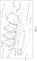
FIG. 3 is a perspective view of an embodiment of a ride vehicle positioned on a variable vehicle ride switch platen in accordance with present techniques; -
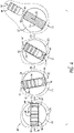
FIG. 4 is a schematic view of configurations of a variable vehicle ride switch in accordance with present techniques; -
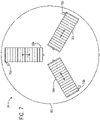
FIG. 5 is a top view of an embodiment of a variable vehicle ride switch in accordance with present techniques; -
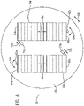
FIG. 6 is a top view of an embodiment of a variable vehicle ride switch in accordance with present techniques; -
FIG. 7 is a schematic representation view of configurations of a variable vehicle ride switch in accordance with present techniques; -
FIG. 8 is a block diagram of a ride system including a variable vehicle ride switch in accordance with present techniques; and -
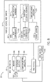
FIG. 9 is a flow diagram of a method for controlling a variable vehicle ride switch in accordance with present techniques. - The present disclosure provides variable vehicle ride switches that may be used in conjunction with amusement park rides to provide adjustment to vehicle direction, orientation, and/or path. Because rides have certain fixed structures that are not easily modified, providing variability within an amusement park ride for repeat riders can extend the enjoyment and lifespan of the ride, which in turn provides cost savings associated with upgrades or replacement of the ride.
- The disclosed variable vehicle ride switches provide benefits over existing fixed-rotation or fixed-pathway switches. In one embodiment, the disclosed variable vehicle ride switches are capable of receiving a vehicle from any one of multiple available input paths and are capable of ejecting the vehicle into any one of the multiple available output paths (which may be the same or different than the input paths, depending on the desired ride configuration). Additionally or alternatively, as disclosed herein, the variable vehicle ride switches are capable of reversing an orientation of travel for a ride vehicle, e.g., forward-facing to backward-facing or vice versa. Alternatively or additionally, the variable vehicle ride switches are capable of dynamically sending a vehicle along a path, such as in a trackless vehicle ride, and at an exit angle from the switch that may be defined by a controller to facilitate certain effects or to propel the vehicle in a desired direction. In one example, the variable vehicle ride switches are capable of reversing a vehicle orientation and sending the reversed vehicle onto a pathway that is among a selection of available pathways for the vehicle. In another example, the next vehicle may be sent onto another pathway in the same orientation without orientation reversal. In this manner, the variable vehicle ride switches facilitate flexibility in various possible ride pathways and orientations for ride vehicles, thus introducing more excitement into the ride. In addition, the variable vehicle ride switches are capable of matching the speed of or accelerating a vehicle moving across the switch, thus reducing bottlenecks. Further, in certain implementations, the variable vehicle ride switches may be configured to accommodate multiple vehicles simultaneously to facilitate increased throughput. Yet further, in certain embodiments, the variable vehicle ride switches permit enhanced direction and orientation variability for ride vehicles without implementing steering or motor functionality on the ride vehicle itself.
-
FIG. 1 is a schematic overview of aride system 10 implemented as a water ride, e.g., having a ride pathway defined by aflume 12 and, for example, having a directional flow of water. The ride system includes one or more variablevehicle ride switches 14. In certain embodiments, the variablevehicle ride switch 14 includes aconveyor 16 positioned in or on abase 20. Thebase 20 may be implemented as a turntable that rotates (e.g., under motor power) relative to a ride surface, e.g., a fixedride floor surface 21. While the disclosed embodiments illustrate thebase 20 as a generally annular platform, it should be understood that other configurations are contemplated. For example, thebase 20 may assume different shapes or sizes. Further, thebase 20 may be implemented as a solid platform or, in certain embodiments, as an open frame that permits water to flow in and around thebase 20, which may help maintain water current patterns in theride system 10. - In one embodiment, the
base 20 of the variablevehicle ride switch 14 is substantially flush with or disposed on theride floor surface 21. In other embodiments, the variablevehicle ride switch 14 is raised relative to theride floor surface 21. Theconveyor 16, being positioned on or in thebase 20, rotates along with thebase 20 when thebase 20 rotates. In certain embodiments, thebase 20 is configured to rotate in a range between 5-360 degrees, 270 degrees or less, 180 degrees or less, or 90 degrees or less from an initial starting position and in either direction and based on activation signals. In specific embodiments, thebase 20 may rotate 15-30 degrees, 30-90 degrees, 90-180 degrees, 180-270 degrees in either direction. Further, the rotation of thebase 20 may be processor controlled and set to a desired rotation and direction depending on the ride configuration. In addition, theconveyor 16 is configured to actuate within thebase 20 and relative to thebase 20. In one embodiment, theconveyor 16 has at least one degree of freedom relative to thebase 20, as provided herein. - The variable
vehicle ride switch 14 is positioned within theride system 10 at an intersection orjunction 23 of multiple pathways 22 (shown aspathways vehicle ride switch 14 permits alignment of theconveyor 16 with a desired pathway 22 among multiple pathways 22 in a variable manner, which in turn permits theride system 10 to be dynamically reconfigured and provides increased enjoyment for passengers. Passengers in a ride vehicle 24 (e.g., a boat or a log) travel through theflume 12 and, at thejunction 23, theride vehicle 24 moves into position onto the variablevehicle ride switch 14. Theride system 10 may include multiple variablevehicle ride switches 14, including multi-vehicle variablevehicle ride switches 14 that includemultiple conveyors conveyor 16 may be implemented, for example, as a belt, roller, or track. In one embodiment, theconveyor 16 may include an arm or hook that couples to an underside of theride vehicle 24 and moves laterally relative to the base 20 to convey theride vehicle 24 across thebase 20. - The variable
vehicle ride switch 14, when theride vehicle 24 is in position, switches to the desired pathway 22 by rotating thebase 20 and actuating theconveyor 16. In particular embodiments, when the variablevehicle ride switch 14 is already positioned to permit theride vehicle 24 to pursue the desired pathway (e.g.,pathway 22b), thebase 20 may remain stationary while theconveyor 16 actuates in a linear fashion to move theride vehicle 24 across the variablevehicle ride switch 14 and onto the desired pathway 22. When asubsequent ride vehicle 24 is positioned on the variablevehicle ride switch 14, the desired pathway 22 may be different (e.g.,pathway 22a), according to the ride configuration, and theride system 10 may control the variablevehicle ride switch 14 accordingly to actuate to align theconveyor 16 with the desired pathway 22. In this manner, theride system 10 may be dynamically reconfigured on a vehicle-by-vehicle basis during a single ride experience such thatdifferent ride vehicles 24 are oriented onto different pathways 22 relative to one another and, therefore, experience different ride events. - As provided herein, the
ride system 10 may be implemented in a trackless manner. Accordingly, the alignment may be within an alignment range that varies according to ride conditions. For example, aligning theconveyor 16 with the desired pathway 22 may include aligning a direction of linear motion of theconveyor 16 in the forwards or backwards direction such that theride vehicle 24 positioned on theconveyor 16, when actuated in a linear fashion off of the variablevehicle ride switch 14, will generally be oriented to travel along the desired pathway 22. In certain embodiments, the alignment may be partial alignment that may permit theride vehicle 24 to enter the desired pathway 22 within a range of potential orientations that permit theride vehicle 24 to travel and be carried by, for example, water current within the confines of theflume 12. Further, as provided herein, the alignment may be in a forward or reverse orientation for theride vehicle 24. -
FIG. 2 is a perspective view of theride vehicle 24 posited on the variablevehicle ride switch 14. The base 20 may be configured as a platform or frame that supports theride vehicle 24. In certain embodiments, thebase 20 is positioned at a depth that approximately corresponds with an estimated depth of theride vehicle 24 such that a bottom surface of the ride vehicle contacts theconveyor 16. Actuation of the variablevehicle ride switch 14 causes the ride vehicle to also move, e.g., to rotate when thebase 20 is rotated and to move linearly according to linear movement of theconveyor 16. Generally, theconveyor 16 may be arranged in shape and size to accommodate theride vehicle 24 and such that the movement of theconveyor 16 provides sufficient motive force to move theride vehicle 24 on and off the variablevehicle ride switch 14. Further, in certain configurations, thebase 20 may also be configured to tilt relative to theride floor surface 21 to produce rolling or pitching motions to provide additional thrill experiences. The variablevehicle ride switch 14 may be at least partially or completely submerged so that passengers in theride vehicle 24 cannot see the motion of the variablevehicle ride switch 14. - The variable
vehicle ride switch 14 includes arotator assembly 30 that drives rotation of thebase 20 and, in certain embodiments, drives movement of theconveyor 16, e.g., via one or more motors or electric/pneumatic actuators. In certain embodiments, the variable vehicle ride switch may include anactuator assembly 36 that drives actuation of theconveyor 16 relative to thebase 20, e.g., via one or more motors. In one embodiment, theactuator assembly 36 may include atrack 38 defining the degree of rotation of theconveyor 16 within or relative to thebase 20. In certain embodiments, the actuator assembly permits a narrower degree of rotation, shown byarrows 39, relative to the base. For example, thebase 20 may be configured for 360 degree rotation while the conveyor is configured for rotation 45 degrees to the left or right. In this manner, granular changes in the orientation of the ride vehicle may be generated by the combined rotation of thebase 20 and theconveyor 16, with the base 20 providing larger changes in orientation and theconveyor 16 proving finer changes or adjustments to the orientation. Theactuator assembly 36 may be positioned relatively closer to one edge of the conveyor 16 (e.g., afront edge 40 or a back edge 42), and an opposing end of the conveyor may be coupled to a pin (not shown) or other feature to permit theconveyor 16 to rotate within thebase 20 and move along thetrack 38. While theactuation assembly 36 is illustrated as including atrack 38, it should be understood that other configurations are contemplated that facilitate the rotation of theconveyor 16. In other embodiments, theactuator assembly 36 may be implemented together with the rotator assembly to drive rotation or actuation of the conveyor from a relatively central position of the conveyor 16 (e.g., a midpoint along a direction of linear motion). - The actuator assembly may include a motor that drives the linear movement of the
conveyor 16 in a forward direction towards thefront edge 40 or a backward direction towards theback edge 42, shown byarrows 48 and relative to avehicle front 44 and vehicle back 46, and that moves theride vehicle 24 on or off the variablevehicle ride switch 14. The conveyor speed/direction may be selected to act as a brake for anonboarding ride vehicle 24. For example, theconveyor 16 may act as a brake to position theride vehicle 24 in a relatively static position on the variablevehicle ride switch 14 as thebase 20 and/or theconveyor 16 rotates. Theconveyor 16 may move in the direction of theback edge 42 to counteract the force of the water current and to hold a relatively static position of theride vehicle 24. The variablevehicle ride switch 14 may also include actuatable barriers or grips that deploy to hold the ride vehicle on the variablevehicle ride switch 14 during actuation and that are released at the completion of the actuation. In other embodiments, theconveyor 16 may operate to accelerate or maintain a speed of theincoming ride vehicle 24. - In another embodiment, as illustrated in
FIG. 3 , the variablevehicle ride switch 14 is implemented to include a platen 49 that rises and lowers under thevehicle 24 to push on a bottom of a hull of thevehicle 24 with enough force to raise the vehicle changing its buoyancy causing it to rest in a stable manner. The platen 49 provides enough normal force and friction to stop the vehicle's forward motion in the constant flow of water. Releasing thevehicle 24 is accomplished by lowering the platen 49 to the point where buoyancy is restored and friction is reduced, and the movement of the water carries thevehicle 24 away from thebase 20. - The actuation of the base and the
conveyor 16 within and/or relative to thebase 20 generates variability in potential exit positions for theride vehicle 24. For example, the ride vehicle may complete a partial circuit or pathway in the forward orientation and then traverse the same pathway in the reverse orientation, permitting riders to see additional ride effects that may not be visible in the forward orientation, which may enhance a ride narrative.FIG. 4 is a schematic diagram of an orientation reversal technique for theride vehicle 24 via the variablevehicle ride switch 14. Theride vehicle 24 enters the variablevehicle ride switch 14 in an entry orientation shown byarrow 51 and with the variablevehicle ride switch 14 in anentry position 52. In one embodiment, theentry position 52 may correspond with theconveyor 16 being generally aligned with theride vehicle 24 such that movement onto the variablevehicle ride switch 14 is along the forward/backward axis (e.g., alongarrows 48,FIG. 2 ) of linear movement of theconveyor 16. Entry to the variablevehicle ride switch 14 may be under current or gravity control. For example, theride vehicle 24 may be implemented without motor power. In other embodiments, theride vehicle 24 is powered by an on-board motor. Theride vehicle 24 enters the variablevehicle ride switch 14 and moves into position on the conveyor with thevehicle front 44 positioned towards the front edge of theconveyor 16. - When the
ride vehicle 24 is in position on theconveyor 16, thebase 20 rotates, shown byarrow 50 relative to theride floor surface 21 to assume an intermediate position 53 in which thebase 20, theconveyor 16, and theride vehicle 24 are all rotated together and away from theentry position 52. While the depicted embodiment shows an approximately 90 degree rotation, it should be understood that the degree of rotation may be established according to desired ride goals. To achieve an exit position 54, theconveyor 16 is rotated relative to the base 20 to facilitate the variablevehicle ride switch 14 assuming the exit position 54. In certain embodiments, actuation to achieve the intermediate position 53 and the exit position 54 may occur in parallel or in series. If the actuation is in series, thebase 20 may be fixed in position while theconveyor 16 rotates to assume the exitposition 54, e.g., changes an angle of theconveyor 16 relative to thebase 20. For example, theconveyor 16 may be oriented at an initial angle, e.g., relative to an imaginary line through a fixed pivot point of theconveyor 16 on thebase 20, and may actuate to change the relative angle of theconveyor 16 to the imaginary line. The change may be a 5-90 degree change in one embodiment. Theconveyor 16 actuates in a linear direction (e.g., shown by arrow 55) to move theride vehicle 24 off the variablevehicle ride switch 14 such that theride vehicle 24 moves along the desired pathway and such that theride vehicle 24 is reversed relative to theentry orientation 51 and the vehicle back 46 is front-facing along the direction of motion, shown byarrow 56. It should be understood that the movements of thebase 20 and theconveyor 16 may occur in parallel or in series. The reversal of orientation or change in orientation may occur while thevehicle 24 is positioned on the variablevehicle ride switch 14 between the steps of receiving thevehicle 24 and ejecting thevehicle 24. In one embodiment, the reversal of orientation may permit thevehicle 24 to be ejected back into the receiving pathway, but in the reverse orientation. - While certain embodiments are shown in the context of variable vehicle ride switches 14 that accommodate a
single ride vehicle 24 at one time, it should be understood that the variablevehicle ride switch 14 may accommodate two ormore ride vehicles 24 simultaneously.FIG. 5 is an embodiment of the variablevehicle ride switch 14 includingmultiple conveyors multiple ride vehicles 24 to be reoriented simultaneously, bottlenecks in the ride may be avoided. While in certain embodiments it may be enjoyable for passengers in oneride vehicle 24 to see the passengers in anadjacent ride vehicle 24 on the variablevehicle ride switch 14, in other embodiments the variablevehicle ride switch 14 may include abarrier 58 positioned at least at passenger eye level that blocks the view and maintains a more immersive experience. Thebarrier 58 may be implemented as a ride-themed object (e.g., a decorative object). - In the depicted embodiment, the
conveyor 16b may actuate, for example about a midpoint, to align theconveyor 16b (and anyride vehicle 24 positioned on theconveyor 16b) with the desiredpathway 22a. Theconveyor 16b may actuate to align with thepathway 22a at a first time point while theconveyor 16a actuates to align withpathway ride vehicles 24 are released in series. In another embodiment, theconveyors ride vehicles 24 simultaneously. Depending on the configuration of the pathways 22, the variablevehicle ride switch 14 may receive the vehicles at the same time or at different time points (e.g., receive afirst ride vehicle 24 before receiving asecond ride vehicle 24, actuate to realign theride vehicles 24 with different pathways 22, and then release theride vehicles 24 simultaneously and in opposite directions and/or orientations. -
FIG. 6 is an example of a multiple vehicle variablevehicle ride switch 14 showing an embodiment in which actuation of theconveyor actuator arm back edge 42a or thefront edge 40a) of theconveyor actuator arm conveyor pivot point arrows vehicle ride switch 14 alongarrows base 20 alongarrows 59. In the depicted embodiment, therespective actuator arms conveyors base 20. However, other arrangements are contemplated. For example,FIG. 7 illustrates a tri-conveyor 16 arrangement in which theactuators perimeter 80 of thebase 20. -
FIG. 8 is a block diagram of thesystem 10, and the techniques disclosed herein may be used in conjunction with one or more components of thesystem 10, including the variablevehicle ride switch 14, theride vehicle 24, aride controller 102, and, in certain embodiments, feedback sensors such as ridevehicle position sensors 130. Theride controller 102 may include various components that may allow for interaction with thevehicle 24 and the variablevehicle ride switch 14. While these elements are discussed in the context of theride controller 102, it should be understood that the variablevehicle ride switch 14 may include similar components. For example, theride controller 102 may include aprocessor 104, amemory 106 for storing instructions executable by theprocessor 104 to perform the methods and control actions described herein for theride system 10. Theprocessor 104 may include one or more processing devices, and thememory 106 may include one or more tangible, non-transitory, machine-readable media. By way of example, such machine-readable media can include RAM, ROM, EPROM, EEPROM, CD-ROM, or other optical disk storage, magnetic disk storage or other magnetic storage devices, or any other medium which can be used to carry or store desired program code in the form of machine-executable instructions or data structures and which can be accessed by theprocessor 104 or by any general purpose or special purpose computer or other machine with a processor. In addition, theride controller 102 may be configured to receive inputs via anoperator interface 108 and communicate over wired or wireless communication pathways viacommunication circuitry 110 with theride vehicle 24 and/or the variablevehicle ride switch 14. - Further, the variable
vehicle ride switch 14 includes or is coupled to one or more controllers, such as a base controller 120 that controls arotation assembly 30 that, for example, includes a base motor. The base controller 120, in turn, may be communicatively coupled to theride controller 102, which provides outputs or activation signals that cause the base controller 120 to drive therotation assembly 30. The variablevehicle ride switch 14 may also include a conveyor controller 124 that that drives anactuator assembly 36. The conveyor controller 124 may be communicatively coupled to theride controller 102, which provides outputs or activation signals that cause the conveyor controller 124 to drive theactuator assembly 36. The variablevehicle ride switch 14 may include apower source 126 andcommunications circuitry 128 to facilitate communication with theride controller 102. - The
ride vehicle 24 may be coupled to a position tracking system for monitoring position in theride system 10. In one embodiment, the position tracking system includes one or more ridevehicle position sensors 130, which may be coupled to theride vehicle 24 or may be distributed throughout theride system 10. Theride system 10 may determine ride vehicle position via the position tracking system that interacts with ridevehicle position sensors 130 or other suitable techniques for determining vehicle position. For example, thesystem 10 may include an external sensor, such as a camera, that tracks the positions of theride vehicles 24 and provides data to theride controller 102. In addition, theride vehicle 24 may include transmitters, such as RFID transmitters, that provide signals to theride controller 102 and that may be used to determine position information. In another embodiment, thevehicle position sensors 130 may be weight or pressure sensors positioned within the ride system, e.g. on the variablevehicle ride switch 14, to provide a signal that aride vehicle 24 is in position on theconveyor 16. In another embodiment, thevehicle position sensors 130 may be optical sensors that track when theride vehicle 24 passes certain positions within the ride system. - In one embodiment, data is transferred between the
ride controller 102, the vehicle positionssensors 130, and the variablevehicle ride switch 14 at least in part via a wireless network. Theride system 10 may communicate data indicative of the status and/or position of the ride vehicle to theride controller 102. Such data may include a vehicle identifier for anindividual ride vehicle 24 and associated position, velocity, traveling direction, or the like. Based on the data, theride controller 102 may send instructions to the variablevehicle ride switch 14 to dictate the pathway (e.g., pathway 22, seeFIG. 1 ) of theride vehicle 24. In accordance with the present disclosure, theride controller 102 may control each of a plurality of variable vehicle ride switches 14 in theride system 10 independently. -
FIG. 9 is a flow diagram of amethod 150 that includes a step of receiving vehicle position information (block 152), e.g., via one or more ridevehicle position sensors 130, for one ormore ride vehicles 24. In one embodiment, the position information is a position relative to the variablevehicle ride switch 14. Alternatively or additionally, the position of anindividual ride vehicle 24 relative to the variablevehicle ride switch 14 may be estimated based on historical travel times between ride locations. When the position information provides information that the ride vehicle is on or near the variablevehicle ride switch 14, theride controller 102 provides an activation signal to the variable vehicle ride switch 14 (block 154). In certain embodiments, the activation signal may be provided in advance of the arrival of theride vehicle 24 to align the variablevehicle ride switch 14 with theincoming ride vehicle 24. When the ride vehicle is in position, the activation signal causes rotation of the base (block 156) and actuation of the conveyor 16 (block 158), which may occur in series or in parallel. The degree of rotation of thebase 20 and actuation of the conveyor is established by theride controller 102 and may be an activation signal. - The
ride system 10 may use position information from the ridevehicle position sensors 130 as feedback to theride controller 102, which in turn may control the variablevehicle ride switch 14 to control pathway selection and vehicle spacing based on the position information. For example, if theride system 10 is configured such that aparticular vehicle 24 of a plurality ofvehicles 24 in the ride is programmed to progress down a pathway that is determined to be backed up or have insufficient spacing between theride vehicles 24 based on vehicle position information, theride system 10 may dynamically adjust the rotation and/or actuation of the variablevehicle ride switch 14 to address vehicle spacing. In one embodiment, theride controller 102 may provide a signal to theactuator assembly 36 to provide vehicle braking via a reversed direction of theconveyor 16 to hold the vehicle in place on the variablevehicle ride switch 14 until the vehicle spacing has adjusted to a desired minimum distance betweenadjacent ride vehicles 24. In another embodiment, theconveyor 16 may be sped up to decrease vehicle spacing. Further, the variablevehicle ride switch 14 may be actuated to a different selected pathway than an initial programming selection based on ride traffic. As provided herein, the activation signals may be dynamically adjusted during the course of the ride to permit real-time variability. - While only certain features of the invention have been illustrated and described herein, many modifications and changes will occur to those skilled in the art. It is, therefore, to be understood that the appended claims are intended to cover all such modifications and changes as fall within the true spirit of the invention. While certain disclosed embodiments have been disclosed in the context of amusement or theme parks, it should be understood that certain embodiments may also relate to other uses. Further, it should be understood that certain elements of the disclosed embodiments may be combined or exchanged with one another. While certain disclosed embodiments are generally described in the context of water rides, water slides, or rides that include a water component, it should be understood that the variable vehicle ride switches as provided herein may also be used in other contexts and with non-water based rides.
- The techniques presented and claimed herein are referenced and applied to material objects and concrete examples of a practical nature that demonstrably improve the present technical field and, as such, are not abstract, intangible or purely theoretical. Further, if any claims appended to the end of this specification contain one or more elements designated as "means for [perform]ing [a function]..." or "step for [perform]ing [a function]...", it is intended that such elements are to be interpreted under 35 U.S.C. 112(f). However, for any claims containing elements designated in any other manner, it is intended that such elements are not to be interpreted under 35 U.S.C. 112(f).
- Alternative expressions of the inventive concept are set out in the following numbered clauses:
- 1. A vehicle ride, comprising:
- a variable vehicle ride switch comprising:
- a base configured to rotate with respect to a ride surface;
- a base controller configured to receive an activation signal to cause the base to rotate; and
- at least one conveyor positioned on the base and configured to rotate together with the base and configured to actuate relative to the base to move a ride vehicle onto or off of the base;
- a plurality of vehicle pathways, wherein the variable vehicle ride switch is positioned at a junction of the plurality of vehicle pathways; and
- a ride controller programmed with instructions to provide the activation signal to the base controller to cause the base to rotate to at least partially align the at least one conveyor with a vehicle pathway of the plurality of vehicle pathways.
- a variable vehicle ride switch comprising:
- 2. The vehicle ride of
clause 1, wherein the activation signal causes the base to rotate to at least partially align the at least one conveyor with a first vehicle pathway of the plurality of vehicle pathways when a first ride vehicle is on the at least one conveyor and to cause the base to rotate to at least partially align the at least one conveyor with a second vehicle pathway of the plurality of vehicle pathways when a second ride vehicle is on the at least one conveyor subsequent to the first ride vehicle. - 3. The vehicle ride of
clause 1, wherein the at least one conveyor comprises a first end and a second end and wherein the activation signal causes the base to rotate to at least partially align the first end or the second end with at least one vehicle pathway of the plurality of vehicle pathways. - 4. The vehicle ride of clause 3, wherein the activation signal causes the base to rotate to at least partially align the first end with a first vehicle pathway of the plurality of vehicle pathways such that a ride vehicle on the at least one conveyor exits the variable vehicle ride switch in a reversed direction relative to entry onto the variable vehicle ride switch.
- 5. The vehicle ride of clause 4, wherein the activation signal causes the base to rotate to at least partially align the second end with the first vehicle pathway such that a second ride vehicle on the at least one conveyor exits the variable vehicle ride switch in a same direction relative to entry onto the variable vehicle ride switch.
- 6. The vehicle ride of
clause 1, wherein the at least one conveyor comprises at least a first conveyor and a second conveyor, and wherein the second conveyor is configured to actuate to move another ride vehicle onto or off of the base such that the variable vehicle ride switch is configured to accommodate a plurality of vehicles simultaneously. - 7. The vehicle ride of clause 6, wherein the variable vehicle ride switch comprises a barrier between the first conveyor and the second conveyor.
- 8. The vehicle ride of clause 6, wherein the activation signal causes the base to rotate to at least partially align the first conveyor with a first vehicle pathway of the plurality of vehicle pathways and the second conveyor with a second vehicle pathway of the plurality of vehicle pathways.
- 9. The vehicle ride of
clause 1, wherein the vehicle ride is a water ride and the variable vehicle ride switch is submerged in water. - 10. The vehicle ride of
clause 1, wherein the at least one conveyor is configured to actuate relative to the base in response to the activation signal such that the vehicle exits the variable vehicle ride switch at a speed that is slower than a vehicle speed at entry. - 11. The vehicle ride of
clause 1, wherein the at least one conveyor is configured to actuate relative to the base in response to the activation signal such that the vehicle exits the variable vehicle ride switch at a speed that is faster or equal to a vehicle speed at entry. - 12. The vehicle ride of
clause 1, wherein the base is configured to move with at least one additional degree of freedom relative to the ride surface. - 13. The vehicle ride of
clause 12, wherein the base is configured to tilt or rise relative to the ride surface. - 14. The vehicle ride of
clause 1, wherein the at least one conveyor is configured to actuate relative to the base in response to the activation signal to fully align a partial alignment with the vehicle pathway of the plurality of vehicle pathways. - 15. The vehicle ride of
clause 14, wherein the at least one conveyor is configured to rotate within the base in response to the activation signal. - 16. The vehicle ride of
clause 1, wherein the at least one conveyer is configured to have at least two degrees of movement relative to the base. - 17. A method, comprising:
- receiving a first ride vehicle on a variable vehicle ride switch;
- receiving a second ride vehicle on the variable vehicle ride switch;
- rotating a base of the variable vehicle ride switch to a first exit position while the first ride vehicle is on the variable vehicle ride switch;
- conveying the first ride vehicle off of the variable vehicle ride switch at the first exit position of the base;
- rotating the base of the variable vehicle ride switch to a second exit position of the base while the second ride vehicle is on the variable vehicle ride switch; and conveying the second ride vehicle off of the variable vehicle ride switch at the second exit position, wherein the second exit position is different from the first exit position.
- 18. The method of clause 17, wherein the first ride vehicle is received by the variable vehicle ride switch at a first starting position of the base and rotating the base to the first exit position comprises a rotation of 270 degrees or less from the first starting position.
- 19. The method of clause 18, wherein the second ride vehicle is received by the variable vehicle ride switch at the first exit position of the base and rotating the base to the second exit position comprises a second rotation of 270 degrees or less from the first exit position.
- 20. The method of clause 18, comprising receiving a third ride vehicle on the variable vehicle ride switch when the variable vehicle ride switch is at the first starting position of the base and such that the first ride vehicle and the second ride vehicle are on the base simultaneously.
- 21. The method of
clause 20, wherein the first ride vehicle and the second ride vehicle are both conveyed from the base at the first exit position. - 22. The method of
clause 21, wherein the first ride vehicle and the second ride vehicle are both conveyed from the base at the first exit position in opposite directions and onto different vehicle pathways. - 23. The method of clause 17, wherein the first ride vehicle and the second ride vehicle are on the base simultaneously.
- 24. The method of clause 17, wherein the second ride vehicle is received by the variable vehicle ride switch subsequent to receiving the first ride vehicle.
- 25. The method of clause 17, wherein rotating the base to the first exit position comprises aligning the first ride vehicle with a first vehicle pathway.
- 26. The method of clause 25, wherein the aligning comprises reversing an orientation of the first ride vehicle.
- 27. The method of clause 17, wherein conveying the first ride vehicle off of the variable vehicle ride switch at the first exit position of the base comprises actuating a conveyor from a first angle to a second angle within the base.
- 28. The method of clause 17, wherein conveying the second ride vehicle off of the variable vehicle ride switch at the second exit position of the base comprises rotating a conveyor within the base.
- 29. The method of clause 17, comprising receiving an activation signal and rotating the base to the first exit position and the second exit position based on the activation signal.
- 30. A variable vehicle ride switch comprising:
- a base configured to rotate with respect to a ride surface;
- at least one conveyor positioned on the base and configured to actuate relative to the base to move a ride vehicle towards or away from an outer edge of the base and to change an angle or orientation of the at least one conveyor within the base; and
- a controller configured to receive an activation signal to cause the base to rotate and to cause the at least one conveyor to actuate.
- 31. The variable vehicle ride switch of
clause 30, wherein the at least one conveyor is configured to rotate relative to the base when the base is in a fixed position. - 32. The variable vehicle ride switch of
clause 30, wherein the at least one conveyor comprises a belt. - 33. The variable vehicle ride switch of
clause 30, wherein the at least one conveyor comprises a first conveyor and a second conveyor.
Claims (15)
- A variable vehicle ride switch comprising:a base configured to rotate with respect to a ride surface;at least one conveyor positioned on the base and configured to actuate relative to the base to move a ride vehicle towards or away from an outer edge of the base and to change an angle or orientation of the at least one conveyor within the base; anda controller configured to receive an activation signal to cause the base to rotate and to cause the at least one conveyor to actuate.
- The variable vehicle ride switch of claim 1, wherein the at least one conveyor is configured to rotate relative to the base when the base is in a fixed position.
- The variable vehicle ride switch of claim 1 or claim 2, wherein the at least one conveyor comprises a belt.
- The variable vehicle ride switch of claim 1, wherein the at least one conveyor comprises a first conveyor and a second conveyor.
- The variable vehicle ride switch of claim 4, wherein the second conveyor is configured to actuate to move another ride vehicle onto or off of the base such that the variable vehicle ride switch is configured to accommodate a plurality of ride vehicles simultaneously.
- The variable vehicle ride switch of claim 5, wherein the activation signal causes the base to rotate to at least partially align the first conveyor with a first vehicle pathway of a plurality of vehicle pathways and the second conveyor with a second vehicle pathway of the plurality of vehicle pathways.
- The variable vehicle ride switch of claim 1, wherein the at least one conveyor is configured to actuate relative to the base in response to the activation signal such that one of the following: (a) the ride vehicle exits the variable vehicle ride switch at a speed that is slower than a vehicle speed at entry; or (b) the ride vehicle exits the variable vehicle ride switch at a speed that is faster than or equal to the vehicle speed on entry.
- A method of operating a variable vehicle ride switch, the variable vehicle ride switch comprising a controller, a base and at least one conveyor positioned on the base, the method comprising:receiving, by the controller, an activation signal; andin response to receiving the activation signal:rotating the base with respect to a ride surface; andactuating the at least one conveyor relative to the base to move a ride vehicle towards or away from an outer edge of the base and to change an angle or orientation of the at least one conveyor within the base.
- The method of claim 8, wherein actuating the at least one conveyor relative to the base comprises rotating the at least one conveyor relative to the base when the base is in a fixed position.
- The method of claim 8 or claim 9, wherein the at least one conveyor comprises a belt.
- The method of claim 8, wherein the at least one conveyor comprises a first conveyor and a second conveyor.
- The method of claim 11, wherein actuating the at least one conveyor relative to the base comprises actuating the second conveyor to move another ride vehicle onto or off of the base such that the variable vehicle ride switch is configured to accommodate a plurality of ride vehicles simultaneously.
- The method of claim 12, wherein rotating the base with respect to a ride surface comprises rotating the base to at least partially align the first conveyor with a first vehicle pathway of a plurality of vehicle pathways and the second conveyor with a second vehicle pathway of the plurality of vehicle pathways.
- The method of claim 8, comprising dynamically adjusting the rotation and/or actuation of the variable vehicle ride switch to address spacing of ride vehicles.
- The method of claim 14, wherein actuating the at least one conveyor relative to the base comprises one of the following: (a) actuating the at least one conveyor to provide vehicle braking such that the ride vehicle exits the variable vehicle ride switch at a speed that is slower than a vehicle speed at entry; or (b) actuating the at least one conveyor such that the ride vehicle exits the variable vehicle ride switch at a speed that is faster than or equal to the vehicle speed on entry.
Applications Claiming Priority (3)
| Application Number | Priority Date | Filing Date | Title |
|---|---|---|---|
| US15/606,833 US10137377B1 (en) | 2017-05-26 | 2017-05-26 | Variable vehicle ride switch |
| PCT/US2018/034204 WO2018217936A1 (en) | 2017-05-26 | 2018-05-23 | Variable vehicle ride switch |
| EP18730614.7A EP3630321B1 (en) | 2017-05-26 | 2018-05-23 | Variable vehicle ride switch |
Related Parent Applications (1)
| Application Number | Title | Priority Date | Filing Date |
|---|---|---|---|
| EP18730614.7A Division EP3630321B1 (en) | 2017-05-26 | 2018-05-23 | Variable vehicle ride switch |
Publications (2)
| Publication Number | Publication Date |
|---|---|
| EP4039346A1 true EP4039346A1 (en) | 2022-08-10 |
| EP4039346B1 EP4039346B1 (en) | 2023-11-08 |
Family
ID=62567869
Family Applications (2)
| Application Number | Title | Priority Date | Filing Date |
|---|---|---|---|
| EP22159786.7A Active EP4039346B1 (en) | 2017-05-26 | 2018-05-23 | Variable vehicle ride switch |
| EP18730614.7A Active EP3630321B1 (en) | 2017-05-26 | 2018-05-23 | Variable vehicle ride switch |
Family Applications After (1)
| Application Number | Title | Priority Date | Filing Date |
|---|---|---|---|
| EP18730614.7A Active EP3630321B1 (en) | 2017-05-26 | 2018-05-23 | Variable vehicle ride switch |
Country Status (10)
| Country | Link |
|---|---|
| US (1) | US10137377B1 (en) |
| EP (2) | EP4039346B1 (en) |
| JP (2) | JP7009512B2 (en) |
| KR (1) | KR102145707B1 (en) |
| CN (1) | CN110650781B (en) |
| CA (1) | CA3064434C (en) |
| ES (2) | ES2915422T3 (en) |
| MY (1) | MY201471A (en) |
| RU (1) | RU2735589C1 (en) |
| WO (1) | WO2018217936A1 (en) |
Families Citing this family (6)
| Publication number | Priority date | Publication date | Assignee | Title |
|---|---|---|---|---|
| US11389719B2 (en) * | 2017-11-10 | 2022-07-19 | Whitewater West Industries Ltd. | Water ride attraction incorporating interactive game play |
| US10625168B2 (en) | 2018-02-28 | 2020-04-21 | Disney Enterprises, Inc. | Boat capture and launch system for water rides |
| US10814236B1 (en) * | 2019-04-29 | 2020-10-27 | Universal City Studios Llc | Coaster transportation system |
| US11813542B2 (en) * | 2020-05-08 | 2023-11-14 | Universal City Studios Llc | Ride vehicle tracking system |
| EP4608529A1 (en) * | 2022-10-24 | 2025-09-03 | Wiegand.Waterrides GmbH | Junction for amusement slide |
| DE102024112855A1 (en) * | 2024-05-07 | 2025-11-13 | Mack Rides Gmbh & Co Kg | Amusement ride, especially water ride |
Citations (5)
| Publication number | Priority date | Publication date | Assignee | Title |
|---|---|---|---|---|
| US536441A (en) * | 1895-03-26 | Inclined railway and water-tobogganing apparatus | ||
| JPH07236773A (en) * | 1994-02-28 | 1995-09-12 | Hitachi Zosen Corp | Boat play facility |
| WO2002022227A2 (en) * | 2000-09-11 | 2002-03-21 | Nbgs International, Inc. | Water amusement system and method |
| US20100160054A1 (en) * | 2008-12-18 | 2010-06-24 | Jeffery Wayne Henry | Themed amusement river ride system |
| US20130045811A1 (en) * | 2012-10-18 | 2013-02-21 | Daniel James Stoker | Motion Ride Method and Apparatus for Illusion of Teleportation |
Family Cites Families (25)
| Publication number | Priority date | Publication date | Assignee | Title |
|---|---|---|---|---|
| US4037738A (en) | 1975-10-09 | 1977-07-26 | American Chain & Cable Company, Inc. | Transfer apparatus |
| SU704636A1 (en) * | 1978-03-27 | 1979-12-25 | Skoblov Oleg L | Vessel for aquatic merry-to-round |
| JPH03261494A (en) * | 1990-03-12 | 1991-11-21 | Hitachi Zosen Corp | Facilities for amusement |
| JP2503190Y2 (en) * | 1991-01-18 | 1996-06-26 | 三菱重工業株式会社 | Viewing boat turning device |
| JP3073297B2 (en) | 1992-01-21 | 2000-08-07 | 三菱重工業株式会社 | Boat swivel equipment |
| JPH06218146A (en) * | 1993-01-27 | 1994-08-09 | Ishii Iron Works Co Ltd | Speed-controllable carrying device of running/ descending device for leisure |
| JPH07100269A (en) * | 1993-10-07 | 1995-04-18 | Bridgestone Corp | Gliding game facility by water flow and unit water course used for the same |
| JPH07108090A (en) | 1993-10-14 | 1995-04-25 | Sansei Yusoki Kk | Amusement vehicle |
| JPH08112455A (en) * | 1994-01-31 | 1996-05-07 | Japan Riyuujiyu:Kk | Vehicle carrying system |
| JP2926648B2 (en) * | 1995-05-11 | 1999-07-28 | モノレール工業株式会社 | Traveling tool transport device and traveling tool transport method |
| US6006672A (en) | 1998-02-03 | 1999-12-28 | O.D. Hopkins Associates, Incorporated | Boat reversing waterway |
| JP2923497B1 (en) * | 1998-04-22 | 1999-07-26 | 株式会社エイ・ティ・アール知能映像通信研究所 | Motion sensation generator |
| JP2000157749A (en) * | 1998-11-25 | 2000-06-13 | Suzuka Circuitland Co Ltd | Rotary game device |
| AU1922300A (en) | 1998-12-04 | 2000-06-26 | Thomson Industries Inc. | Method and apparatus for transferring a carriage assembly between rails |
| JP3394747B2 (en) * | 2000-07-19 | 2003-04-07 | 泉陽興業株式会社 | Recreational vehicle equipment |
| US6502688B1 (en) | 2000-10-30 | 2003-01-07 | Pace Packaging Corp. | Method and apparatus for high speed plastic container unscrambling |
| US6743108B2 (en) * | 2000-12-12 | 2004-06-01 | Proslide Technology Inc. | Random path flume ride |
| JP4041724B2 (en) | 2002-11-18 | 2008-01-30 | ユニ・チャーム株式会社 | Article reversing device |
| DE20316695U1 (en) | 2003-10-29 | 2005-03-17 | Raw Tex Internat Ag Schaan | Hoist for cars in log flume or scenic railway has a vertical support with lifting platforms on tracked drives to lift loaded cars and to return empty to the bottom start point |
| US20050092580A1 (en) | 2003-11-03 | 2005-05-05 | Clemens William J. | Conveyor belt transport alignment device, method and system |
| US8038541B1 (en) | 2004-02-17 | 2011-10-18 | Jared Freeman Solomon | Motion based system |
| JP5721268B2 (en) * | 2010-08-11 | 2015-05-20 | ビーエルデーオリエンタル株式会社 | Facilities equipped with eating and drinking facilities and methods for attracting customers at the facilities |
| US8578857B2 (en) | 2011-12-08 | 2013-11-12 | Disney Enterprises, Inc. | Amusement park ride with passenger loading separated from vehicle insertion into simulators |
| US8905852B2 (en) * | 2012-04-11 | 2014-12-09 | Yuri Geylik | Roadside personalized entertainment system and method |
| US9526997B2 (en) * | 2014-07-22 | 2016-12-27 | Universal City Studios Llc | Vehicle transportation room system and method |
-
2017
- 2017-05-26 US US15/606,833 patent/US10137377B1/en active Active
-
2018
- 2018-05-23 CN CN201880034731.4A patent/CN110650781B/en active Active
- 2018-05-23 MY MYPI2019006509A patent/MY201471A/en unknown
- 2018-05-23 CA CA3064434A patent/CA3064434C/en active Active
- 2018-05-23 WO PCT/US2018/034204 patent/WO2018217936A1/en not_active Ceased
- 2018-05-23 ES ES18730614T patent/ES2915422T3/en active Active
- 2018-05-23 EP EP22159786.7A patent/EP4039346B1/en active Active
- 2018-05-23 JP JP2019565367A patent/JP7009512B2/en active Active
- 2018-05-23 ES ES22159786T patent/ES2971894T3/en active Active
- 2018-05-23 KR KR1020197038035A patent/KR102145707B1/en active Active
- 2018-05-23 RU RU2019143119A patent/RU2735589C1/en active
- 2018-05-23 EP EP18730614.7A patent/EP3630321B1/en active Active
-
2021
- 2021-06-25 JP JP2021105967A patent/JP7200300B2/en active Active
Patent Citations (5)
| Publication number | Priority date | Publication date | Assignee | Title |
|---|---|---|---|---|
| US536441A (en) * | 1895-03-26 | Inclined railway and water-tobogganing apparatus | ||
| JPH07236773A (en) * | 1994-02-28 | 1995-09-12 | Hitachi Zosen Corp | Boat play facility |
| WO2002022227A2 (en) * | 2000-09-11 | 2002-03-21 | Nbgs International, Inc. | Water amusement system and method |
| US20100160054A1 (en) * | 2008-12-18 | 2010-06-24 | Jeffery Wayne Henry | Themed amusement river ride system |
| US20130045811A1 (en) * | 2012-10-18 | 2013-02-21 | Daniel James Stoker | Motion Ride Method and Apparatus for Illusion of Teleportation |
Also Published As
| Publication number | Publication date |
|---|---|
| JP7009512B2 (en) | 2022-01-25 |
| US10137377B1 (en) | 2018-11-27 |
| EP3630321A1 (en) | 2020-04-08 |
| ES2915422T3 (en) | 2022-06-22 |
| RU2735589C1 (en) | 2020-11-05 |
| ES2971894T3 (en) | 2024-06-10 |
| JP2021166743A (en) | 2021-10-21 |
| JP7200300B2 (en) | 2023-01-06 |
| CA3064434C (en) | 2021-03-30 |
| EP4039346B1 (en) | 2023-11-08 |
| WO2018217936A1 (en) | 2018-11-29 |
| EP3630321B1 (en) | 2022-03-09 |
| CN110650781B (en) | 2021-03-12 |
| KR20200006597A (en) | 2020-01-20 |
| MY201471A (en) | 2024-02-24 |
| JP2020521563A (en) | 2020-07-27 |
| CN110650781A (en) | 2020-01-03 |
| CA3064434A1 (en) | 2018-11-29 |
| US20180339233A1 (en) | 2018-11-29 |
| KR102145707B1 (en) | 2020-08-19 |
Similar Documents
| Publication | Publication Date | Title |
|---|---|---|
| CA3064434C (en) | Variable vehicle ride switch | |
| EP3810298B1 (en) | Multi-dimensional bogie and track system | |
| KR20170066561A (en) | Actuatable motion base system | |
| KR102606025B1 (en) | System and method for positioning vehicles on amusement park rides | |
| KR20170009943A (en) | Virtual attraction controller | |
| KR20210113281A (en) | Systems and methods for controlling entertainment figures | |
| US20240181358A1 (en) | Rotating platform coaster | |
| HK40020540A (en) | Variable vehicle ride switch | |
| HK40020540B (en) | Variable vehicle ride switch | |
| KR20210135597A (en) | Vertical Motion Drive System for Ride Systems | |
| CN119384307A (en) | Systems and methods for dynamic multi-experience ride systems | |
| US20240408502A1 (en) | Round ride systems and methods | |
| US20250296005A1 (en) | Anti-gravity attraction system with lever assembly | |
| WO2024253892A1 (en) | Round ride systems and methods | |
| HK40017635B (en) | System and method for positioning vehicles of an amusement park attraction | |
| HK40046969A (en) | Multi-dimensional bogie and track system | |
| HK40046969B (en) | Multi-dimensional bogie and track system |
Legal Events
| Date | Code | Title | Description |
|---|---|---|---|
| PUAI | Public reference made under article 153(3) epc to a published international application that has entered the european phase |
Free format text: ORIGINAL CODE: 0009012 |
|
| STAA | Information on the status of an ep patent application or granted ep patent |
Free format text: STATUS: THE APPLICATION HAS BEEN PUBLISHED |
|
| AC | Divisional application: reference to earlier application |
Ref document number: 3630321 Country of ref document: EP Kind code of ref document: P |
|
| AK | Designated contracting states |
Kind code of ref document: A1 Designated state(s): AL AT BE BG CH CY CZ DE DK EE ES FI FR GB GR HR HU IE IS IT LI LT LU LV MC MK MT NL NO PL PT RO RS SE SI SK SM TR |
|
| STAA | Information on the status of an ep patent application or granted ep patent |
Free format text: STATUS: REQUEST FOR EXAMINATION WAS MADE |
|
| 17P | Request for examination filed |
Effective date: 20230120 |
|
| RBV | Designated contracting states (corrected) |
Designated state(s): AL AT BE BG CH CY CZ DE DK EE ES FI FR GB GR HR HU IE IS IT LI LT LU LV MC MK MT NL NO PL PT RO RS SE SI SK SM TR |
|
| GRAP | Despatch of communication of intention to grant a patent |
Free format text: ORIGINAL CODE: EPIDOSNIGR1 |
|
| STAA | Information on the status of an ep patent application or granted ep patent |
Free format text: STATUS: GRANT OF PATENT IS INTENDED |
|
| INTG | Intention to grant announced |
Effective date: 20230609 |
|
| GRAS | Grant fee paid |
Free format text: ORIGINAL CODE: EPIDOSNIGR3 |
|
| GRAA | (expected) grant |
Free format text: ORIGINAL CODE: 0009210 |
|
| STAA | Information on the status of an ep patent application or granted ep patent |
Free format text: STATUS: THE PATENT HAS BEEN GRANTED |
|
| AC | Divisional application: reference to earlier application |
Ref document number: 3630321 Country of ref document: EP Kind code of ref document: P |
|
| AK | Designated contracting states |
Kind code of ref document: B1 Designated state(s): AL AT BE BG CH CY CZ DE DK EE ES FI FR GB GR HR HU IE IS IT LI LT LU LV MC MK MT NL NO PL PT RO RS SE SI SK SM TR |
|
| REG | Reference to a national code |
Ref country code: GB Ref legal event code: FG4D |
|
| REG | Reference to a national code |
Ref country code: CH Ref legal event code: EP |
|
| P01 | Opt-out of the competence of the unified patent court (upc) registered |
Effective date: 20231020 |
|
| REG | Reference to a national code |
Ref country code: DE Ref legal event code: R096 Ref document number: 602018061036 Country of ref document: DE |
|
| REG | Reference to a national code |
Ref country code: IE Ref legal event code: FG4D |
|
| REG | Reference to a national code |
Ref country code: LT Ref legal event code: MG9D |
|
| REG | Reference to a national code |
Ref country code: NL Ref legal event code: MP Effective date: 20231108 |
|
| PG25 | Lapsed in a contracting state [announced via postgrant information from national office to epo] |
Ref country code: GR Free format text: LAPSE BECAUSE OF FAILURE TO SUBMIT A TRANSLATION OF THE DESCRIPTION OR TO PAY THE FEE WITHIN THE PRESCRIBED TIME-LIMIT Effective date: 20240209 |
|
| PG25 | Lapsed in a contracting state [announced via postgrant information from national office to epo] |
Ref country code: IS Free format text: LAPSE BECAUSE OF FAILURE TO SUBMIT A TRANSLATION OF THE DESCRIPTION OR TO PAY THE FEE WITHIN THE PRESCRIBED TIME-LIMIT Effective date: 20240308 |
|
| PG25 | Lapsed in a contracting state [announced via postgrant information from national office to epo] |
Ref country code: LT Free format text: LAPSE BECAUSE OF FAILURE TO SUBMIT A TRANSLATION OF THE DESCRIPTION OR TO PAY THE FEE WITHIN THE PRESCRIBED TIME-LIMIT Effective date: 20231108 |
|
| PG25 | Lapsed in a contracting state [announced via postgrant information from national office to epo] |
Ref country code: NL Free format text: LAPSE BECAUSE OF FAILURE TO SUBMIT A TRANSLATION OF THE DESCRIPTION OR TO PAY THE FEE WITHIN THE PRESCRIBED TIME-LIMIT Effective date: 20231108 |
|
| PG25 | Lapsed in a contracting state [announced via postgrant information from national office to epo] |
Ref country code: NL Free format text: LAPSE BECAUSE OF FAILURE TO SUBMIT A TRANSLATION OF THE DESCRIPTION OR TO PAY THE FEE WITHIN THE PRESCRIBED TIME-LIMIT Effective date: 20231108 Ref country code: LT Free format text: LAPSE BECAUSE OF FAILURE TO SUBMIT A TRANSLATION OF THE DESCRIPTION OR TO PAY THE FEE WITHIN THE PRESCRIBED TIME-LIMIT Effective date: 20231108 Ref country code: IS Free format text: LAPSE BECAUSE OF FAILURE TO SUBMIT A TRANSLATION OF THE DESCRIPTION OR TO PAY THE FEE WITHIN THE PRESCRIBED TIME-LIMIT Effective date: 20240308 Ref country code: GR Free format text: LAPSE BECAUSE OF FAILURE TO SUBMIT A TRANSLATION OF THE DESCRIPTION OR TO PAY THE FEE WITHIN THE PRESCRIBED TIME-LIMIT Effective date: 20240209 Ref country code: BG Free format text: LAPSE BECAUSE OF FAILURE TO SUBMIT A TRANSLATION OF THE DESCRIPTION OR TO PAY THE FEE WITHIN THE PRESCRIBED TIME-LIMIT Effective date: 20240208 Ref country code: PT Free format text: LAPSE BECAUSE OF FAILURE TO SUBMIT A TRANSLATION OF THE DESCRIPTION OR TO PAY THE FEE WITHIN THE PRESCRIBED TIME-LIMIT Effective date: 20240308 |
|
| PG25 | Lapsed in a contracting state [announced via postgrant information from national office to epo] |
Ref country code: SE Free format text: LAPSE BECAUSE OF FAILURE TO SUBMIT A TRANSLATION OF THE DESCRIPTION OR TO PAY THE FEE WITHIN THE PRESCRIBED TIME-LIMIT Effective date: 20231108 Ref country code: RS Free format text: LAPSE BECAUSE OF FAILURE TO SUBMIT A TRANSLATION OF THE DESCRIPTION OR TO PAY THE FEE WITHIN THE PRESCRIBED TIME-LIMIT Effective date: 20231108 Ref country code: PL Free format text: LAPSE BECAUSE OF FAILURE TO SUBMIT A TRANSLATION OF THE DESCRIPTION OR TO PAY THE FEE WITHIN THE PRESCRIBED TIME-LIMIT Effective date: 20231108 Ref country code: NO Free format text: LAPSE BECAUSE OF FAILURE TO SUBMIT A TRANSLATION OF THE DESCRIPTION OR TO PAY THE FEE WITHIN THE PRESCRIBED TIME-LIMIT Effective date: 20240208 Ref country code: LV Free format text: LAPSE BECAUSE OF FAILURE TO SUBMIT A TRANSLATION OF THE DESCRIPTION OR TO PAY THE FEE WITHIN THE PRESCRIBED TIME-LIMIT Effective date: 20231108 Ref country code: HR Free format text: LAPSE BECAUSE OF FAILURE TO SUBMIT A TRANSLATION OF THE DESCRIPTION OR TO PAY THE FEE WITHIN THE PRESCRIBED TIME-LIMIT Effective date: 20231108 |
|
| REG | Reference to a national code |
Ref country code: ES Ref legal event code: FG2A Ref document number: 2971894 Country of ref document: ES Kind code of ref document: T3 Effective date: 20240610 |
|
| REG | Reference to a national code |
Ref country code: AT Ref legal event code: UEP Ref document number: 1629111 Country of ref document: AT Kind code of ref document: T Effective date: 20231108 |
|
| PG25 | Lapsed in a contracting state [announced via postgrant information from national office to epo] |
Ref country code: DK Free format text: LAPSE BECAUSE OF FAILURE TO SUBMIT A TRANSLATION OF THE DESCRIPTION OR TO PAY THE FEE WITHIN THE PRESCRIBED TIME-LIMIT Effective date: 20231108 |
|
| PG25 | Lapsed in a contracting state [announced via postgrant information from national office to epo] |
Ref country code: CZ Free format text: LAPSE BECAUSE OF FAILURE TO SUBMIT A TRANSLATION OF THE DESCRIPTION OR TO PAY THE FEE WITHIN THE PRESCRIBED TIME-LIMIT Effective date: 20231108 |
|
| PG25 | Lapsed in a contracting state [announced via postgrant information from national office to epo] |
Ref country code: SK Free format text: LAPSE BECAUSE OF FAILURE TO SUBMIT A TRANSLATION OF THE DESCRIPTION OR TO PAY THE FEE WITHIN THE PRESCRIBED TIME-LIMIT Effective date: 20231108 |
|
| PG25 | Lapsed in a contracting state [announced via postgrant information from national office to epo] |
Ref country code: SM Free format text: LAPSE BECAUSE OF FAILURE TO SUBMIT A TRANSLATION OF THE DESCRIPTION OR TO PAY THE FEE WITHIN THE PRESCRIBED TIME-LIMIT Effective date: 20231108 Ref country code: SK Free format text: LAPSE BECAUSE OF FAILURE TO SUBMIT A TRANSLATION OF THE DESCRIPTION OR TO PAY THE FEE WITHIN THE PRESCRIBED TIME-LIMIT Effective date: 20231108 Ref country code: RO Free format text: LAPSE BECAUSE OF FAILURE TO SUBMIT A TRANSLATION OF THE DESCRIPTION OR TO PAY THE FEE WITHIN THE PRESCRIBED TIME-LIMIT Effective date: 20231108 Ref country code: EE Free format text: LAPSE BECAUSE OF FAILURE TO SUBMIT A TRANSLATION OF THE DESCRIPTION OR TO PAY THE FEE WITHIN THE PRESCRIBED TIME-LIMIT Effective date: 20231108 Ref country code: DK Free format text: LAPSE BECAUSE OF FAILURE TO SUBMIT A TRANSLATION OF THE DESCRIPTION OR TO PAY THE FEE WITHIN THE PRESCRIBED TIME-LIMIT Effective date: 20231108 Ref country code: CZ Free format text: LAPSE BECAUSE OF FAILURE TO SUBMIT A TRANSLATION OF THE DESCRIPTION OR TO PAY THE FEE WITHIN THE PRESCRIBED TIME-LIMIT Effective date: 20231108 |
|
| REG | Reference to a national code |
Ref country code: DE Ref legal event code: R097 Ref document number: 602018061036 Country of ref document: DE |
|
| PLBE | No opposition filed within time limit |
Free format text: ORIGINAL CODE: 0009261 |
|
| STAA | Information on the status of an ep patent application or granted ep patent |
Free format text: STATUS: NO OPPOSITION FILED WITHIN TIME LIMIT |
|
| 26N | No opposition filed |
Effective date: 20240809 |
|
| PG25 | Lapsed in a contracting state [announced via postgrant information from national office to epo] |
Ref country code: SI Free format text: LAPSE BECAUSE OF FAILURE TO SUBMIT A TRANSLATION OF THE DESCRIPTION OR TO PAY THE FEE WITHIN THE PRESCRIBED TIME-LIMIT Effective date: 20231108 |
|
| PG25 | Lapsed in a contracting state [announced via postgrant information from national office to epo] |
Ref country code: SI Free format text: LAPSE BECAUSE OF FAILURE TO SUBMIT A TRANSLATION OF THE DESCRIPTION OR TO PAY THE FEE WITHIN THE PRESCRIBED TIME-LIMIT Effective date: 20231108 |
|
| PG25 | Lapsed in a contracting state [announced via postgrant information from national office to epo] |
Ref country code: MC Free format text: LAPSE BECAUSE OF FAILURE TO SUBMIT A TRANSLATION OF THE DESCRIPTION OR TO PAY THE FEE WITHIN THE PRESCRIBED TIME-LIMIT Effective date: 20231108 |
|
| PG25 | Lapsed in a contracting state [announced via postgrant information from national office to epo] |
Ref country code: LU Free format text: LAPSE BECAUSE OF NON-PAYMENT OF DUE FEES Effective date: 20240523 |
|
| PG25 | Lapsed in a contracting state [announced via postgrant information from national office to epo] |
Ref country code: MC Free format text: LAPSE BECAUSE OF FAILURE TO SUBMIT A TRANSLATION OF THE DESCRIPTION OR TO PAY THE FEE WITHIN THE PRESCRIBED TIME-LIMIT Effective date: 20231108 Ref country code: LU Free format text: LAPSE BECAUSE OF NON-PAYMENT OF DUE FEES Effective date: 20240523 |
|
| REG | Reference to a national code |
Ref country code: BE Ref legal event code: MM Effective date: 20240531 |
|
| PG25 | Lapsed in a contracting state [announced via postgrant information from national office to epo] |
Ref country code: IE Free format text: LAPSE BECAUSE OF NON-PAYMENT OF DUE FEES Effective date: 20240523 |
|
| PG25 | Lapsed in a contracting state [announced via postgrant information from national office to epo] |
Ref country code: BE Free format text: LAPSE BECAUSE OF NON-PAYMENT OF DUE FEES Effective date: 20240531 |
|
| PGFP | Annual fee paid to national office [announced via postgrant information from national office to epo] |
Ref country code: DE Payment date: 20250529 Year of fee payment: 8 |
|
| PGFP | Annual fee paid to national office [announced via postgrant information from national office to epo] |
Ref country code: ES Payment date: 20250602 Year of fee payment: 8 |
|
| PGFP | Annual fee paid to national office [announced via postgrant information from national office to epo] |
Ref country code: IT Payment date: 20250521 Year of fee payment: 8 |
|
| PGFP | Annual fee paid to national office [announced via postgrant information from national office to epo] |
Ref country code: FR Payment date: 20250526 Year of fee payment: 8 |
|
| PGFP | Annual fee paid to national office [announced via postgrant information from national office to epo] |
Ref country code: CH Payment date: 20250601 Year of fee payment: 8 |
|
| PGFP | Annual fee paid to national office [announced via postgrant information from national office to epo] |
Ref country code: AT Payment date: 20250505 Year of fee payment: 8 |
|
| PG25 | Lapsed in a contracting state [announced via postgrant information from national office to epo] |
Ref country code: CY Free format text: LAPSE BECAUSE OF FAILURE TO SUBMIT A TRANSLATION OF THE DESCRIPTION OR TO PAY THE FEE WITHIN THE PRESCRIBED TIME-LIMIT; INVALID AB INITIO Effective date: 20180523 |
|
| PG25 | Lapsed in a contracting state [announced via postgrant information from national office to epo] |
Ref country code: HU Free format text: LAPSE BECAUSE OF FAILURE TO SUBMIT A TRANSLATION OF THE DESCRIPTION OR TO PAY THE FEE WITHIN THE PRESCRIBED TIME-LIMIT; INVALID AB INITIO Effective date: 20180523 |
|
| PG25 | Lapsed in a contracting state [announced via postgrant information from national office to epo] |
Ref country code: FI Free format text: LAPSE BECAUSE OF FAILURE TO SUBMIT A TRANSLATION OF THE DESCRIPTION OR TO PAY THE FEE WITHIN THE PRESCRIBED TIME-LIMIT Effective date: 20231108 |
|
| PGFP | Annual fee paid to national office [announced via postgrant information from national office to epo] |
Ref country code: GB Payment date: 20260327 Year of fee payment: 9 |