EP4039320A1 - Ouvertures latérales d'entrée de sang - Google Patents
Ouvertures latérales d'entrée de sang Download PDFInfo
- Publication number
- EP4039320A1 EP4039320A1 EP22163653.3A EP22163653A EP4039320A1 EP 4039320 A1 EP4039320 A1 EP 4039320A1 EP 22163653 A EP22163653 A EP 22163653A EP 4039320 A1 EP4039320 A1 EP 4039320A1
- Authority
- EP
- European Patent Office
- Prior art keywords
- impeller
- applications
- distal
- pump
- typically
- Prior art date
- Legal status (The legal status is an assumption and is not a legal conclusion. Google has not performed a legal analysis and makes no representation as to the accuracy of the status listed.)
- Pending
Links
- 239000008280 blood Substances 0.000 claims abstract description 153
- 210000004369 blood Anatomy 0.000 claims abstract description 153
- 210000005240 left ventricle Anatomy 0.000 claims abstract description 142
- 210000000709 aorta Anatomy 0.000 claims abstract description 52
- 210000001765 aortic valve Anatomy 0.000 claims abstract description 8
- 230000002861 ventricular Effects 0.000 claims description 223
- 230000004044 response Effects 0.000 claims description 21
- 230000017531 blood circulation Effects 0.000 claims description 19
- 210000003540 papillary muscle Anatomy 0.000 claims description 12
- 210000003698 chordae tendineae Anatomy 0.000 claims description 11
- 230000033001 locomotion Effects 0.000 description 85
- 239000000463 material Substances 0.000 description 78
- 239000010410 layer Substances 0.000 description 75
- 238000010926 purge Methods 0.000 description 50
- 239000012530 fluid Substances 0.000 description 48
- 230000000747 cardiac effect Effects 0.000 description 42
- 238000000034 method Methods 0.000 description 41
- 239000013536 elastomeric material Substances 0.000 description 36
- 230000008878 coupling Effects 0.000 description 29
- 238000010168 coupling process Methods 0.000 description 29
- 238000005859 coupling reaction Methods 0.000 description 29
- 238000005086 pumping Methods 0.000 description 25
- 238000005259 measurement Methods 0.000 description 22
- 238000009530 blood pressure measurement Methods 0.000 description 21
- 229910001000 nickel titanium Inorganic materials 0.000 description 21
- HLXZNVUGXRDIFK-UHFFFAOYSA-N nickel titanium Chemical compound [Ti].[Ti].[Ti].[Ti].[Ti].[Ti].[Ti].[Ti].[Ti].[Ti].[Ti].[Ni].[Ni].[Ni].[Ni].[Ni].[Ni].[Ni].[Ni].[Ni].[Ni].[Ni].[Ni].[Ni].[Ni] HLXZNVUGXRDIFK-UHFFFAOYSA-N 0.000 description 21
- 230000004907 flux Effects 0.000 description 19
- 238000000576 coating method Methods 0.000 description 15
- 238000003780 insertion Methods 0.000 description 15
- 230000037431 insertion Effects 0.000 description 15
- 210000004027 cell Anatomy 0.000 description 14
- 239000011248 coating agent Substances 0.000 description 14
- 239000007822 coupling agent Substances 0.000 description 14
- 229920002614 Polyether block amide Polymers 0.000 description 12
- 210000002376 aorta thoracic Anatomy 0.000 description 12
- 229920001971 elastomer Polymers 0.000 description 12
- 239000000806 elastomer Substances 0.000 description 12
- 229920001296 polysiloxane Polymers 0.000 description 12
- 229910001285 shape-memory alloy Inorganic materials 0.000 description 12
- 230000036772 blood pressure Effects 0.000 description 11
- 229920002635 polyurethane Polymers 0.000 description 11
- 239000004814 polyurethane Substances 0.000 description 11
- -1 silane compound Chemical class 0.000 description 10
- 210000001367 artery Anatomy 0.000 description 9
- 229920000728 polyester Polymers 0.000 description 9
- 230000007704 transition Effects 0.000 description 9
- 206010018910 Haemolysis Diseases 0.000 description 8
- 239000004433 Thermoplastic polyurethane Substances 0.000 description 8
- 230000008588 hemolysis Effects 0.000 description 8
- 230000001965 increasing effect Effects 0.000 description 8
- 229920000139 polyethylene terephthalate Polymers 0.000 description 8
- 239000005020 polyethylene terephthalate Substances 0.000 description 8
- 229920002803 thermoplastic polyurethane Polymers 0.000 description 8
- 210000003484 anatomy Anatomy 0.000 description 7
- 230000006870 function Effects 0.000 description 7
- 125000000524 functional group Chemical group 0.000 description 7
- 239000004417 polycarbonate Substances 0.000 description 7
- 229920000515 polycarbonate Polymers 0.000 description 7
- 230000000541 pulsatile effect Effects 0.000 description 7
- 239000012781 shape memory material Substances 0.000 description 7
- 229910045601 alloy Inorganic materials 0.000 description 6
- 239000000956 alloy Substances 0.000 description 6
- 230000008859 change Effects 0.000 description 6
- 238000002474 experimental method Methods 0.000 description 6
- 210000004115 mitral valve Anatomy 0.000 description 6
- 229910000077 silane Inorganic materials 0.000 description 6
- 210000001519 tissue Anatomy 0.000 description 6
- 125000003118 aryl group Chemical group 0.000 description 5
- 239000013013 elastic material Substances 0.000 description 5
- 238000000926 separation method Methods 0.000 description 5
- RYECOJGRJDOGPP-UHFFFAOYSA-N Ethylurea Chemical compound CCNC(N)=O RYECOJGRJDOGPP-UHFFFAOYSA-N 0.000 description 4
- 238000004891 communication Methods 0.000 description 4
- 230000006835 compression Effects 0.000 description 4
- 238000007906 compression Methods 0.000 description 4
- 238000012417 linear regression Methods 0.000 description 4
- 238000004519 manufacturing process Methods 0.000 description 4
- 229920001343 polytetrafluoroethylene Polymers 0.000 description 4
- 239000004810 polytetrafluoroethylene Substances 0.000 description 4
- 230000008569 process Effects 0.000 description 4
- 210000005241 right ventricle Anatomy 0.000 description 4
- 238000003856 thermoforming Methods 0.000 description 4
- 238000009423 ventilation Methods 0.000 description 4
- 238000004804 winding Methods 0.000 description 4
- WQZGKKKJIJFFOK-GASJEMHNSA-N Glucose Natural products OC[C@H]1OC(O)[C@H](O)[C@@H](O)[C@@H]1O WQZGKKKJIJFFOK-GASJEMHNSA-N 0.000 description 3
- 210000004204 blood vessel Anatomy 0.000 description 3
- 238000004364 calculation method Methods 0.000 description 3
- 230000007423 decrease Effects 0.000 description 3
- 238000007598 dipping method Methods 0.000 description 3
- 230000023597 hemostasis Effects 0.000 description 3
- 238000000338 in vitro Methods 0.000 description 3
- 230000036512 infertility Effects 0.000 description 3
- 238000013178 mathematical model Methods 0.000 description 3
- 239000000155 melt Substances 0.000 description 3
- 239000002184 metal Substances 0.000 description 3
- 229910052751 metal Inorganic materials 0.000 description 3
- 238000013146 percutaneous coronary intervention Methods 0.000 description 3
- 238000005507 spraying Methods 0.000 description 3
- 239000010935 stainless steel Substances 0.000 description 3
- 229910001220 stainless steel Inorganic materials 0.000 description 3
- PEDCQBHIVMGVHV-UHFFFAOYSA-N Glycerine Chemical compound OCC(O)CO PEDCQBHIVMGVHV-UHFFFAOYSA-N 0.000 description 2
- 239000004696 Poly ether ether ketone Substances 0.000 description 2
- 241000590419 Polygonia interrogationis Species 0.000 description 2
- 239000004642 Polyimide Substances 0.000 description 2
- WQZGKKKJIJFFOK-VFUOTHLCSA-N beta-D-glucose Chemical compound OC[C@H]1O[C@@H](O)[C@H](O)[C@@H](O)[C@@H]1O WQZGKKKJIJFFOK-VFUOTHLCSA-N 0.000 description 2
- 230000005540 biological transmission Effects 0.000 description 2
- 238000000071 blow moulding Methods 0.000 description 2
- 238000002788 crimping Methods 0.000 description 2
- 230000006378 damage Effects 0.000 description 2
- 230000003205 diastolic effect Effects 0.000 description 2
- 238000013213 extrapolation Methods 0.000 description 2
- 239000000835 fiber Substances 0.000 description 2
- 239000008103 glucose Substances 0.000 description 2
- 210000002751 lymph Anatomy 0.000 description 2
- 239000005445 natural material Substances 0.000 description 2
- 230000036961 partial effect Effects 0.000 description 2
- 229920002530 polyetherether ketone Polymers 0.000 description 2
- 229920001721 polyimide Polymers 0.000 description 2
- 229920000642 polymer Polymers 0.000 description 2
- 230000002829 reductive effect Effects 0.000 description 2
- 230000002787 reinforcement Effects 0.000 description 2
- 210000005245 right atrium Anatomy 0.000 description 2
- 238000007493 shaping process Methods 0.000 description 2
- 238000004904 shortening Methods 0.000 description 2
- 239000007921 spray Substances 0.000 description 2
- 238000002604 ultrasonography Methods 0.000 description 2
- 210000005166 vasculature Anatomy 0.000 description 2
- 210000003462 vein Anatomy 0.000 description 2
- 208000031229 Cardiomyopathies Diseases 0.000 description 1
- 229910000684 Cobalt-chrome Inorganic materials 0.000 description 1
- 229910000760 Hardened steel Inorganic materials 0.000 description 1
- 208000009378 Low Cardiac Output Diseases 0.000 description 1
- 208000009525 Myocarditis Diseases 0.000 description 1
- 239000004677 Nylon Substances 0.000 description 1
- BLRPTPMANUNPDV-UHFFFAOYSA-N Silane Chemical compound [SiH4] BLRPTPMANUNPDV-UHFFFAOYSA-N 0.000 description 1
- 229910000831 Steel Inorganic materials 0.000 description 1
- WAIPAZQMEIHHTJ-UHFFFAOYSA-N [Cr].[Co] Chemical compound [Cr].[Co] WAIPAZQMEIHHTJ-UHFFFAOYSA-N 0.000 description 1
- 230000001154 acute effect Effects 0.000 description 1
- 206010000891 acute myocardial infarction Diseases 0.000 description 1
- 239000000853 adhesive Substances 0.000 description 1
- 230000001070 adhesive effect Effects 0.000 description 1
- 238000004458 analytical method Methods 0.000 description 1
- 238000004873 anchoring Methods 0.000 description 1
- 206010003119 arrhythmia Diseases 0.000 description 1
- 230000004323 axial length Effects 0.000 description 1
- 230000015572 biosynthetic process Effects 0.000 description 1
- 210000005242 cardiac chamber Anatomy 0.000 description 1
- 206010007625 cardiogenic shock Diseases 0.000 description 1
- 239000000919 ceramic Substances 0.000 description 1
- 239000010952 cobalt-chrome Substances 0.000 description 1
- 238000004590 computer program Methods 0.000 description 1
- 238000010276 construction Methods 0.000 description 1
- 238000005520 cutting process Methods 0.000 description 1
- 230000002950 deficient Effects 0.000 description 1
- 238000001739 density measurement Methods 0.000 description 1
- 230000001419 dependent effect Effects 0.000 description 1
- 230000006866 deterioration Effects 0.000 description 1
- 239000008121 dextrose Substances 0.000 description 1
- 238000001035 drying Methods 0.000 description 1
- 238000005516 engineering process Methods 0.000 description 1
- 230000002708 enhancing effect Effects 0.000 description 1
- 210000001105 femoral artery Anatomy 0.000 description 1
- 235000011187 glycerol Nutrition 0.000 description 1
- 230000004217 heart function Effects 0.000 description 1
- 208000011316 hemodynamic instability Diseases 0.000 description 1
- 230000002452 interceptive effect Effects 0.000 description 1
- 238000007914 intraventricular administration Methods 0.000 description 1
- 210000004731 jugular vein Anatomy 0.000 description 1
- 210000005248 left atrial appendage Anatomy 0.000 description 1
- 210000005246 left atrium Anatomy 0.000 description 1
- 230000000670 limiting effect Effects 0.000 description 1
- 239000007788 liquid Substances 0.000 description 1
- 230000001926 lymphatic effect Effects 0.000 description 1
- 230000007257 malfunction Effects 0.000 description 1
- 239000000203 mixture Substances 0.000 description 1
- 238000012986 modification Methods 0.000 description 1
- 230000004048 modification Effects 0.000 description 1
- PHQOGHDTIVQXHL-UHFFFAOYSA-N n'-(3-trimethoxysilylpropyl)ethane-1,2-diamine Chemical compound CO[Si](OC)(OC)CCCNCCN PHQOGHDTIVQXHL-UHFFFAOYSA-N 0.000 description 1
- 229920001778 nylon Polymers 0.000 description 1
- 210000001147 pulmonary artery Anatomy 0.000 description 1
- 210000003102 pulmonary valve Anatomy 0.000 description 1
- 210000002321 radial artery Anatomy 0.000 description 1
- 238000011084 recovery Methods 0.000 description 1
- 210000002796 renal vein Anatomy 0.000 description 1
- 239000002356 single layer Substances 0.000 description 1
- 125000006850 spacer group Chemical group 0.000 description 1
- 230000003068 static effect Effects 0.000 description 1
- 239000010959 steel Substances 0.000 description 1
- 210000001321 subclavian vein Anatomy 0.000 description 1
- 230000001360 synchronised effect Effects 0.000 description 1
- 238000012360 testing method Methods 0.000 description 1
- 238000003466 welding Methods 0.000 description 1
Images


Classifications
-
- A—HUMAN NECESSITIES
- A61—MEDICAL OR VETERINARY SCIENCE; HYGIENE
- A61M—DEVICES FOR INTRODUCING MEDIA INTO, OR ONTO, THE BODY; DEVICES FOR TRANSDUCING BODY MEDIA OR FOR TAKING MEDIA FROM THE BODY; DEVICES FOR PRODUCING OR ENDING SLEEP OR STUPOR
- A61M60/00—Blood pumps; Devices for mechanical circulatory actuation; Balloon pumps for circulatory assistance
- A61M60/10—Location thereof with respect to the patient's body
- A61M60/122—Implantable pumps or pumping devices, i.e. the blood being pumped inside the patient's body
- A61M60/126—Implantable pumps or pumping devices, i.e. the blood being pumped inside the patient's body implantable via, into, inside, in line, branching on, or around a blood vessel
- A61M60/13—Implantable pumps or pumping devices, i.e. the blood being pumped inside the patient's body implantable via, into, inside, in line, branching on, or around a blood vessel by means of a catheter allowing explantation, e.g. catheter pumps temporarily introduced via the vascular system
-
- A—HUMAN NECESSITIES
- A61—MEDICAL OR VETERINARY SCIENCE; HYGIENE
- A61B—DIAGNOSIS; SURGERY; IDENTIFICATION
- A61B5/00—Measuring for diagnostic purposes; Identification of persons
- A61B5/02—Detecting, measuring or recording pulse, heart rate, blood pressure or blood flow; Combined pulse/heart-rate/blood pressure determination; Evaluating a cardiovascular condition not otherwise provided for, e.g. using combinations of techniques provided for in this group with electrocardiography or electroauscultation; Heart catheters for measuring blood pressure
- A61B5/021—Measuring pressure in heart or blood vessels
- A61B5/02141—Details of apparatus construction, e.g. pump units or housings therefor, cuff pressurising systems, arrangements of fluid conduits or circuits
-
- A—HUMAN NECESSITIES
- A61—MEDICAL OR VETERINARY SCIENCE; HYGIENE
- A61B—DIAGNOSIS; SURGERY; IDENTIFICATION
- A61B5/00—Measuring for diagnostic purposes; Identification of persons
- A61B5/02—Detecting, measuring or recording pulse, heart rate, blood pressure or blood flow; Combined pulse/heart-rate/blood pressure determination; Evaluating a cardiovascular condition not otherwise provided for, e.g. using combinations of techniques provided for in this group with electrocardiography or electroauscultation; Heart catheters for measuring blood pressure
- A61B5/021—Measuring pressure in heart or blood vessels
- A61B5/0215—Measuring pressure in heart or blood vessels by means inserted into the body
-
- A—HUMAN NECESSITIES
- A61—MEDICAL OR VETERINARY SCIENCE; HYGIENE
- A61M—DEVICES FOR INTRODUCING MEDIA INTO, OR ONTO, THE BODY; DEVICES FOR TRANSDUCING BODY MEDIA OR FOR TAKING MEDIA FROM THE BODY; DEVICES FOR PRODUCING OR ENDING SLEEP OR STUPOR
- A61M60/00—Blood pumps; Devices for mechanical circulatory actuation; Balloon pumps for circulatory assistance
- A61M60/10—Location thereof with respect to the patient's body
- A61M60/122—Implantable pumps or pumping devices, i.e. the blood being pumped inside the patient's body
- A61M60/126—Implantable pumps or pumping devices, i.e. the blood being pumped inside the patient's body implantable via, into, inside, in line, branching on, or around a blood vessel
- A61M60/135—Implantable pumps or pumping devices, i.e. the blood being pumped inside the patient's body implantable via, into, inside, in line, branching on, or around a blood vessel inside a blood vessel, e.g. using grafting
-
- A—HUMAN NECESSITIES
- A61—MEDICAL OR VETERINARY SCIENCE; HYGIENE
- A61M—DEVICES FOR INTRODUCING MEDIA INTO, OR ONTO, THE BODY; DEVICES FOR TRANSDUCING BODY MEDIA OR FOR TAKING MEDIA FROM THE BODY; DEVICES FOR PRODUCING OR ENDING SLEEP OR STUPOR
- A61M60/00—Blood pumps; Devices for mechanical circulatory actuation; Balloon pumps for circulatory assistance
- A61M60/10—Location thereof with respect to the patient's body
- A61M60/122—Implantable pumps or pumping devices, i.e. the blood being pumped inside the patient's body
- A61M60/126—Implantable pumps or pumping devices, i.e. the blood being pumped inside the patient's body implantable via, into, inside, in line, branching on, or around a blood vessel
- A61M60/148—Implantable pumps or pumping devices, i.e. the blood being pumped inside the patient's body implantable via, into, inside, in line, branching on, or around a blood vessel in line with a blood vessel using resection or like techniques, e.g. permanent endovascular heart assist devices
-
- A—HUMAN NECESSITIES
- A61—MEDICAL OR VETERINARY SCIENCE; HYGIENE
- A61M—DEVICES FOR INTRODUCING MEDIA INTO, OR ONTO, THE BODY; DEVICES FOR TRANSDUCING BODY MEDIA OR FOR TAKING MEDIA FROM THE BODY; DEVICES FOR PRODUCING OR ENDING SLEEP OR STUPOR
- A61M60/00—Blood pumps; Devices for mechanical circulatory actuation; Balloon pumps for circulatory assistance
- A61M60/10—Location thereof with respect to the patient's body
- A61M60/122—Implantable pumps or pumping devices, i.e. the blood being pumped inside the patient's body
- A61M60/165—Implantable pumps or pumping devices, i.e. the blood being pumped inside the patient's body implantable in, on, or around the heart
- A61M60/17—Implantable pumps or pumping devices, i.e. the blood being pumped inside the patient's body implantable in, on, or around the heart inside a ventricle, e.g. intraventricular balloon pumps
- A61M60/174—Implantable pumps or pumping devices, i.e. the blood being pumped inside the patient's body implantable in, on, or around the heart inside a ventricle, e.g. intraventricular balloon pumps discharging the blood to the ventricle or arterial system via a cannula internal to the ventricle or arterial system
-
- A—HUMAN NECESSITIES
- A61—MEDICAL OR VETERINARY SCIENCE; HYGIENE
- A61M—DEVICES FOR INTRODUCING MEDIA INTO, OR ONTO, THE BODY; DEVICES FOR TRANSDUCING BODY MEDIA OR FOR TAKING MEDIA FROM THE BODY; DEVICES FOR PRODUCING OR ENDING SLEEP OR STUPOR
- A61M60/00—Blood pumps; Devices for mechanical circulatory actuation; Balloon pumps for circulatory assistance
- A61M60/10—Location thereof with respect to the patient's body
- A61M60/122—Implantable pumps or pumping devices, i.e. the blood being pumped inside the patient's body
- A61M60/165—Implantable pumps or pumping devices, i.e. the blood being pumped inside the patient's body implantable in, on, or around the heart
- A61M60/178—Implantable pumps or pumping devices, i.e. the blood being pumped inside the patient's body implantable in, on, or around the heart drawing blood from a ventricle and returning the blood to the arterial system via a cannula external to the ventricle, e.g. left or right ventricular assist devices
-
- A—HUMAN NECESSITIES
- A61—MEDICAL OR VETERINARY SCIENCE; HYGIENE
- A61M—DEVICES FOR INTRODUCING MEDIA INTO, OR ONTO, THE BODY; DEVICES FOR TRANSDUCING BODY MEDIA OR FOR TAKING MEDIA FROM THE BODY; DEVICES FOR PRODUCING OR ENDING SLEEP OR STUPOR
- A61M60/00—Blood pumps; Devices for mechanical circulatory actuation; Balloon pumps for circulatory assistance
- A61M60/20—Type thereof
- A61M60/205—Non-positive displacement blood pumps
- A61M60/216—Non-positive displacement blood pumps including a rotating member acting on the blood, e.g. impeller
- A61M60/226—Non-positive displacement blood pumps including a rotating member acting on the blood, e.g. impeller the blood flow through the rotating member having mainly radial components
-
- A—HUMAN NECESSITIES
- A61—MEDICAL OR VETERINARY SCIENCE; HYGIENE
- A61M—DEVICES FOR INTRODUCING MEDIA INTO, OR ONTO, THE BODY; DEVICES FOR TRANSDUCING BODY MEDIA OR FOR TAKING MEDIA FROM THE BODY; DEVICES FOR PRODUCING OR ENDING SLEEP OR STUPOR
- A61M60/00—Blood pumps; Devices for mechanical circulatory actuation; Balloon pumps for circulatory assistance
- A61M60/20—Type thereof
- A61M60/205—Non-positive displacement blood pumps
- A61M60/216—Non-positive displacement blood pumps including a rotating member acting on the blood, e.g. impeller
- A61M60/237—Non-positive displacement blood pumps including a rotating member acting on the blood, e.g. impeller the blood flow through the rotating member having mainly axial components, e.g. axial flow pumps
-
- A—HUMAN NECESSITIES
- A61—MEDICAL OR VETERINARY SCIENCE; HYGIENE
- A61M—DEVICES FOR INTRODUCING MEDIA INTO, OR ONTO, THE BODY; DEVICES FOR TRANSDUCING BODY MEDIA OR FOR TAKING MEDIA FROM THE BODY; DEVICES FOR PRODUCING OR ENDING SLEEP OR STUPOR
- A61M60/00—Blood pumps; Devices for mechanical circulatory actuation; Balloon pumps for circulatory assistance
- A61M60/40—Details relating to driving
- A61M60/403—Details relating to driving for non-positive displacement blood pumps
- A61M60/408—Details relating to driving for non-positive displacement blood pumps the force acting on the blood contacting member being mechanical, e.g. transmitted by a shaft or cable
- A61M60/411—Details relating to driving for non-positive displacement blood pumps the force acting on the blood contacting member being mechanical, e.g. transmitted by a shaft or cable generated by an electromotor
- A61M60/414—Details relating to driving for non-positive displacement blood pumps the force acting on the blood contacting member being mechanical, e.g. transmitted by a shaft or cable generated by an electromotor transmitted by a rotating cable, e.g. for blood pumps mounted on a catheter
-
- A—HUMAN NECESSITIES
- A61—MEDICAL OR VETERINARY SCIENCE; HYGIENE
- A61M—DEVICES FOR INTRODUCING MEDIA INTO, OR ONTO, THE BODY; DEVICES FOR TRANSDUCING BODY MEDIA OR FOR TAKING MEDIA FROM THE BODY; DEVICES FOR PRODUCING OR ENDING SLEEP OR STUPOR
- A61M60/00—Blood pumps; Devices for mechanical circulatory actuation; Balloon pumps for circulatory assistance
- A61M60/40—Details relating to driving
- A61M60/403—Details relating to driving for non-positive displacement blood pumps
- A61M60/419—Details relating to driving for non-positive displacement blood pumps the force acting on the blood contacting member being permanent magnetic, e.g. from a rotating magnetic coupling between driving and driven magnets
-
- A—HUMAN NECESSITIES
- A61—MEDICAL OR VETERINARY SCIENCE; HYGIENE
- A61M—DEVICES FOR INTRODUCING MEDIA INTO, OR ONTO, THE BODY; DEVICES FOR TRANSDUCING BODY MEDIA OR FOR TAKING MEDIA FROM THE BODY; DEVICES FOR PRODUCING OR ENDING SLEEP OR STUPOR
- A61M60/00—Blood pumps; Devices for mechanical circulatory actuation; Balloon pumps for circulatory assistance
- A61M60/40—Details relating to driving
- A61M60/403—Details relating to driving for non-positive displacement blood pumps
- A61M60/422—Details relating to driving for non-positive displacement blood pumps the force acting on the blood contacting member being electromagnetic, e.g. using canned motor pumps
-
- A—HUMAN NECESSITIES
- A61—MEDICAL OR VETERINARY SCIENCE; HYGIENE
- A61M—DEVICES FOR INTRODUCING MEDIA INTO, OR ONTO, THE BODY; DEVICES FOR TRANSDUCING BODY MEDIA OR FOR TAKING MEDIA FROM THE BODY; DEVICES FOR PRODUCING OR ENDING SLEEP OR STUPOR
- A61M60/00—Blood pumps; Devices for mechanical circulatory actuation; Balloon pumps for circulatory assistance
- A61M60/50—Details relating to control
- A61M60/508—Electronic control means, e.g. for feedback regulation
- A61M60/515—Regulation using real-time patient data
- A61M60/523—Regulation using real-time patient data using blood flow data, e.g. from blood flow transducers
-
- A—HUMAN NECESSITIES
- A61—MEDICAL OR VETERINARY SCIENCE; HYGIENE
- A61M—DEVICES FOR INTRODUCING MEDIA INTO, OR ONTO, THE BODY; DEVICES FOR TRANSDUCING BODY MEDIA OR FOR TAKING MEDIA FROM THE BODY; DEVICES FOR PRODUCING OR ENDING SLEEP OR STUPOR
- A61M60/00—Blood pumps; Devices for mechanical circulatory actuation; Balloon pumps for circulatory assistance
- A61M60/50—Details relating to control
- A61M60/508—Electronic control means, e.g. for feedback regulation
- A61M60/515—Regulation using real-time patient data
- A61M60/531—Regulation using real-time patient data using blood pressure data, e.g. from blood pressure sensors
-
- A—HUMAN NECESSITIES
- A61—MEDICAL OR VETERINARY SCIENCE; HYGIENE
- A61M—DEVICES FOR INTRODUCING MEDIA INTO, OR ONTO, THE BODY; DEVICES FOR TRANSDUCING BODY MEDIA OR FOR TAKING MEDIA FROM THE BODY; DEVICES FOR PRODUCING OR ENDING SLEEP OR STUPOR
- A61M60/00—Blood pumps; Devices for mechanical circulatory actuation; Balloon pumps for circulatory assistance
- A61M60/50—Details relating to control
- A61M60/508—Electronic control means, e.g. for feedback regulation
- A61M60/538—Regulation using real-time blood pump operational parameter data, e.g. motor current
- A61M60/546—Regulation using real-time blood pump operational parameter data, e.g. motor current of blood flow, e.g. by adapting rotor speed
-
- A—HUMAN NECESSITIES
- A61—MEDICAL OR VETERINARY SCIENCE; HYGIENE
- A61M—DEVICES FOR INTRODUCING MEDIA INTO, OR ONTO, THE BODY; DEVICES FOR TRANSDUCING BODY MEDIA OR FOR TAKING MEDIA FROM THE BODY; DEVICES FOR PRODUCING OR ENDING SLEEP OR STUPOR
- A61M60/00—Blood pumps; Devices for mechanical circulatory actuation; Balloon pumps for circulatory assistance
- A61M60/50—Details relating to control
- A61M60/508—Electronic control means, e.g. for feedback regulation
- A61M60/538—Regulation using real-time blood pump operational parameter data, e.g. motor current
- A61M60/554—Regulation using real-time blood pump operational parameter data, e.g. motor current of blood pressure
-
- A—HUMAN NECESSITIES
- A61—MEDICAL OR VETERINARY SCIENCE; HYGIENE
- A61M—DEVICES FOR INTRODUCING MEDIA INTO, OR ONTO, THE BODY; DEVICES FOR TRANSDUCING BODY MEDIA OR FOR TAKING MEDIA FROM THE BODY; DEVICES FOR PRODUCING OR ENDING SLEEP OR STUPOR
- A61M60/00—Blood pumps; Devices for mechanical circulatory actuation; Balloon pumps for circulatory assistance
- A61M60/80—Constructional details other than related to driving
- A61M60/802—Constructional details other than related to driving of non-positive displacement blood pumps
- A61M60/804—Impellers
- A61M60/806—Vanes or blades
- A61M60/808—Vanes or blades specially adapted for deformable impellers, e.g. expandable impellers
-
- A—HUMAN NECESSITIES
- A61—MEDICAL OR VETERINARY SCIENCE; HYGIENE
- A61M—DEVICES FOR INTRODUCING MEDIA INTO, OR ONTO, THE BODY; DEVICES FOR TRANSDUCING BODY MEDIA OR FOR TAKING MEDIA FROM THE BODY; DEVICES FOR PRODUCING OR ENDING SLEEP OR STUPOR
- A61M60/00—Blood pumps; Devices for mechanical circulatory actuation; Balloon pumps for circulatory assistance
- A61M60/80—Constructional details other than related to driving
- A61M60/802—Constructional details other than related to driving of non-positive displacement blood pumps
- A61M60/81—Pump housings
- A61M60/812—Vanes or blades, e.g. static flow guides
-
- A—HUMAN NECESSITIES
- A61—MEDICAL OR VETERINARY SCIENCE; HYGIENE
- A61M—DEVICES FOR INTRODUCING MEDIA INTO, OR ONTO, THE BODY; DEVICES FOR TRANSDUCING BODY MEDIA OR FOR TAKING MEDIA FROM THE BODY; DEVICES FOR PRODUCING OR ENDING SLEEP OR STUPOR
- A61M60/00—Blood pumps; Devices for mechanical circulatory actuation; Balloon pumps for circulatory assistance
- A61M60/80—Constructional details other than related to driving
- A61M60/802—Constructional details other than related to driving of non-positive displacement blood pumps
- A61M60/81—Pump housings
- A61M60/816—Sensors arranged on or in the housing, e.g. ultrasound flow sensors
-
- A—HUMAN NECESSITIES
- A61—MEDICAL OR VETERINARY SCIENCE; HYGIENE
- A61M—DEVICES FOR INTRODUCING MEDIA INTO, OR ONTO, THE BODY; DEVICES FOR TRANSDUCING BODY MEDIA OR FOR TAKING MEDIA FROM THE BODY; DEVICES FOR PRODUCING OR ENDING SLEEP OR STUPOR
- A61M60/00—Blood pumps; Devices for mechanical circulatory actuation; Balloon pumps for circulatory assistance
- A61M60/80—Constructional details other than related to driving
- A61M60/802—Constructional details other than related to driving of non-positive displacement blood pumps
- A61M60/818—Bearings
- A61M60/824—Hydrodynamic or fluid film bearings
-
- A—HUMAN NECESSITIES
- A61—MEDICAL OR VETERINARY SCIENCE; HYGIENE
- A61M—DEVICES FOR INTRODUCING MEDIA INTO, OR ONTO, THE BODY; DEVICES FOR TRANSDUCING BODY MEDIA OR FOR TAKING MEDIA FROM THE BODY; DEVICES FOR PRODUCING OR ENDING SLEEP OR STUPOR
- A61M60/00—Blood pumps; Devices for mechanical circulatory actuation; Balloon pumps for circulatory assistance
- A61M60/80—Constructional details other than related to driving
- A61M60/802—Constructional details other than related to driving of non-positive displacement blood pumps
- A61M60/818—Bearings
- A61M60/825—Contact bearings, e.g. ball-and-cup or pivot bearings
-
- A—HUMAN NECESSITIES
- A61—MEDICAL OR VETERINARY SCIENCE; HYGIENE
- A61M—DEVICES FOR INTRODUCING MEDIA INTO, OR ONTO, THE BODY; DEVICES FOR TRANSDUCING BODY MEDIA OR FOR TAKING MEDIA FROM THE BODY; DEVICES FOR PRODUCING OR ENDING SLEEP OR STUPOR
- A61M60/00—Blood pumps; Devices for mechanical circulatory actuation; Balloon pumps for circulatory assistance
- A61M60/80—Constructional details other than related to driving
- A61M60/802—Constructional details other than related to driving of non-positive displacement blood pumps
- A61M60/827—Sealings between moving parts
- A61M60/829—Sealings between moving parts having a purge fluid supply
-
- A—HUMAN NECESSITIES
- A61—MEDICAL OR VETERINARY SCIENCE; HYGIENE
- A61M—DEVICES FOR INTRODUCING MEDIA INTO, OR ONTO, THE BODY; DEVICES FOR TRANSDUCING BODY MEDIA OR FOR TAKING MEDIA FROM THE BODY; DEVICES FOR PRODUCING OR ENDING SLEEP OR STUPOR
- A61M60/00—Blood pumps; Devices for mechanical circulatory actuation; Balloon pumps for circulatory assistance
- A61M60/80—Constructional details other than related to driving
- A61M60/802—Constructional details other than related to driving of non-positive displacement blood pumps
- A61M60/833—Occluders for preventing backflow
-
- A—HUMAN NECESSITIES
- A61—MEDICAL OR VETERINARY SCIENCE; HYGIENE
- A61M—DEVICES FOR INTRODUCING MEDIA INTO, OR ONTO, THE BODY; DEVICES FOR TRANSDUCING BODY MEDIA OR FOR TAKING MEDIA FROM THE BODY; DEVICES FOR PRODUCING OR ENDING SLEEP OR STUPOR
- A61M60/00—Blood pumps; Devices for mechanical circulatory actuation; Balloon pumps for circulatory assistance
- A61M60/80—Constructional details other than related to driving
- A61M60/855—Constructional details other than related to driving of implantable pumps or pumping devices
- A61M60/857—Implantable blood tubes
-
- A—HUMAN NECESSITIES
- A61—MEDICAL OR VETERINARY SCIENCE; HYGIENE
- A61M—DEVICES FOR INTRODUCING MEDIA INTO, OR ONTO, THE BODY; DEVICES FOR TRANSDUCING BODY MEDIA OR FOR TAKING MEDIA FROM THE BODY; DEVICES FOR PRODUCING OR ENDING SLEEP OR STUPOR
- A61M60/00—Blood pumps; Devices for mechanical circulatory actuation; Balloon pumps for circulatory assistance
- A61M60/80—Constructional details other than related to driving
- A61M60/855—Constructional details other than related to driving of implantable pumps or pumping devices
- A61M60/865—Devices for guiding or inserting pumps or pumping devices into the patient's body
-
- A—HUMAN NECESSITIES
- A61—MEDICAL OR VETERINARY SCIENCE; HYGIENE
- A61M—DEVICES FOR INTRODUCING MEDIA INTO, OR ONTO, THE BODY; DEVICES FOR TRANSDUCING BODY MEDIA OR FOR TAKING MEDIA FROM THE BODY; DEVICES FOR PRODUCING OR ENDING SLEEP OR STUPOR
- A61M60/00—Blood pumps; Devices for mechanical circulatory actuation; Balloon pumps for circulatory assistance
- A61M60/80—Constructional details other than related to driving
- A61M60/855—Constructional details other than related to driving of implantable pumps or pumping devices
- A61M60/89—Valves
- A61M60/894—Passive valves, i.e. valves actuated by the blood
- A61M60/896—Passive valves, i.e. valves actuated by the blood having flexible or resilient parts, e.g. flap valves
-
- F—MECHANICAL ENGINEERING; LIGHTING; HEATING; WEAPONS; BLASTING
- F04—POSITIVE - DISPLACEMENT MACHINES FOR LIQUIDS; PUMPS FOR LIQUIDS OR ELASTIC FLUIDS
- F04D—NON-POSITIVE-DISPLACEMENT PUMPS
- F04D15/00—Control, e.g. regulation, of pumps, pumping installations or systems
- F04D15/0066—Control, e.g. regulation, of pumps, pumping installations or systems by changing the speed, e.g. of the driving engine
-
- F—MECHANICAL ENGINEERING; LIGHTING; HEATING; WEAPONS; BLASTING
- F04—POSITIVE - DISPLACEMENT MACHINES FOR LIQUIDS; PUMPS FOR LIQUIDS OR ELASTIC FLUIDS
- F04D—NON-POSITIVE-DISPLACEMENT PUMPS
- F04D25/00—Pumping installations or systems
- F04D25/02—Units comprising pumps and their driving means
-
- F—MECHANICAL ENGINEERING; LIGHTING; HEATING; WEAPONS; BLASTING
- F04—POSITIVE - DISPLACEMENT MACHINES FOR LIQUIDS; PUMPS FOR LIQUIDS OR ELASTIC FLUIDS
- F04D—NON-POSITIVE-DISPLACEMENT PUMPS
- F04D29/00—Details, component parts, or accessories
- F04D29/04—Shafts or bearings, or assemblies thereof
- F04D29/041—Axial thrust balancing
-
- F—MECHANICAL ENGINEERING; LIGHTING; HEATING; WEAPONS; BLASTING
- F04—POSITIVE - DISPLACEMENT MACHINES FOR LIQUIDS; PUMPS FOR LIQUIDS OR ELASTIC FLUIDS
- F04D—NON-POSITIVE-DISPLACEMENT PUMPS
- F04D29/00—Details, component parts, or accessories
- F04D29/04—Shafts or bearings, or assemblies thereof
- F04D29/042—Axially shiftable rotors
-
- F—MECHANICAL ENGINEERING; LIGHTING; HEATING; WEAPONS; BLASTING
- F04—POSITIVE - DISPLACEMENT MACHINES FOR LIQUIDS; PUMPS FOR LIQUIDS OR ELASTIC FLUIDS
- F04D—NON-POSITIVE-DISPLACEMENT PUMPS
- F04D29/00—Details, component parts, or accessories
- F04D29/18—Rotors
- F04D29/181—Axial flow rotors
-
- F—MECHANICAL ENGINEERING; LIGHTING; HEATING; WEAPONS; BLASTING
- F04—POSITIVE - DISPLACEMENT MACHINES FOR LIQUIDS; PUMPS FOR LIQUIDS OR ELASTIC FLUIDS
- F04D—NON-POSITIVE-DISPLACEMENT PUMPS
- F04D29/00—Details, component parts, or accessories
- F04D29/18—Rotors
- F04D29/22—Rotors specially for centrifugal pumps
- F04D29/24—Vanes
- F04D29/247—Vanes elastic or self-adjusting
-
- F—MECHANICAL ENGINEERING; LIGHTING; HEATING; WEAPONS; BLASTING
- F04—POSITIVE - DISPLACEMENT MACHINES FOR LIQUIDS; PUMPS FOR LIQUIDS OR ELASTIC FLUIDS
- F04D—NON-POSITIVE-DISPLACEMENT PUMPS
- F04D3/00—Axial-flow pumps
- F04D3/02—Axial-flow pumps of screw type
-
- F—MECHANICAL ENGINEERING; LIGHTING; HEATING; WEAPONS; BLASTING
- F04—POSITIVE - DISPLACEMENT MACHINES FOR LIQUIDS; PUMPS FOR LIQUIDS OR ELASTIC FLUIDS
- F04D—NON-POSITIVE-DISPLACEMENT PUMPS
- F04D7/00—Pumps adapted for handling specific fluids, e.g. by selection of specific materials for pumps or pump parts
-
- A—HUMAN NECESSITIES
- A61—MEDICAL OR VETERINARY SCIENCE; HYGIENE
- A61B—DIAGNOSIS; SURGERY; IDENTIFICATION
- A61B2562/00—Details of sensors; Constructional details of sensor housings or probes; Accessories for sensors
- A61B2562/02—Details of sensors specially adapted for in-vivo measurements
- A61B2562/0223—Magnetic field sensors
-
- A—HUMAN NECESSITIES
- A61—MEDICAL OR VETERINARY SCIENCE; HYGIENE
- A61M—DEVICES FOR INTRODUCING MEDIA INTO, OR ONTO, THE BODY; DEVICES FOR TRANSDUCING BODY MEDIA OR FOR TAKING MEDIA FROM THE BODY; DEVICES FOR PRODUCING OR ENDING SLEEP OR STUPOR
- A61M2205/00—General characteristics of the apparatus
- A61M2205/02—General characteristics of the apparatus characterised by a particular materials
- A61M2205/0266—Shape memory materials
-
- A—HUMAN NECESSITIES
- A61—MEDICAL OR VETERINARY SCIENCE; HYGIENE
- A61M—DEVICES FOR INTRODUCING MEDIA INTO, OR ONTO, THE BODY; DEVICES FOR TRANSDUCING BODY MEDIA OR FOR TAKING MEDIA FROM THE BODY; DEVICES FOR PRODUCING OR ENDING SLEEP OR STUPOR
- A61M2205/00—General characteristics of the apparatus
- A61M2205/33—Controlling, regulating or measuring
- A61M2205/3317—Electromagnetic, inductive or dielectric measuring means
-
- A—HUMAN NECESSITIES
- A61—MEDICAL OR VETERINARY SCIENCE; HYGIENE
- A61M—DEVICES FOR INTRODUCING MEDIA INTO, OR ONTO, THE BODY; DEVICES FOR TRANSDUCING BODY MEDIA OR FOR TAKING MEDIA FROM THE BODY; DEVICES FOR PRODUCING OR ENDING SLEEP OR STUPOR
- A61M2205/00—General characteristics of the apparatus
- A61M2205/33—Controlling, regulating or measuring
- A61M2205/3327—Measuring
-
- A—HUMAN NECESSITIES
- A61—MEDICAL OR VETERINARY SCIENCE; HYGIENE
- A61M—DEVICES FOR INTRODUCING MEDIA INTO, OR ONTO, THE BODY; DEVICES FOR TRANSDUCING BODY MEDIA OR FOR TAKING MEDIA FROM THE BODY; DEVICES FOR PRODUCING OR ENDING SLEEP OR STUPOR
- A61M2205/00—General characteristics of the apparatus
- A61M2205/33—Controlling, regulating or measuring
- A61M2205/3331—Pressure; Flow
- A61M2205/3334—Measuring or controlling the flow rate
-
- A—HUMAN NECESSITIES
- A61—MEDICAL OR VETERINARY SCIENCE; HYGIENE
- A61M—DEVICES FOR INTRODUCING MEDIA INTO, OR ONTO, THE BODY; DEVICES FOR TRANSDUCING BODY MEDIA OR FOR TAKING MEDIA FROM THE BODY; DEVICES FOR PRODUCING OR ENDING SLEEP OR STUPOR
- A61M2205/00—General characteristics of the apparatus
- A61M2205/33—Controlling, regulating or measuring
- A61M2205/3331—Pressure; Flow
- A61M2205/3344—Measuring or controlling pressure at the body treatment site
-
- A—HUMAN NECESSITIES
- A61—MEDICAL OR VETERINARY SCIENCE; HYGIENE
- A61M—DEVICES FOR INTRODUCING MEDIA INTO, OR ONTO, THE BODY; DEVICES FOR TRANSDUCING BODY MEDIA OR FOR TAKING MEDIA FROM THE BODY; DEVICES FOR PRODUCING OR ENDING SLEEP OR STUPOR
- A61M2205/00—General characteristics of the apparatus
- A61M2205/33—Controlling, regulating or measuring
- A61M2205/3365—Rotational speed
-
- A—HUMAN NECESSITIES
- A61—MEDICAL OR VETERINARY SCIENCE; HYGIENE
- A61M—DEVICES FOR INTRODUCING MEDIA INTO, OR ONTO, THE BODY; DEVICES FOR TRANSDUCING BODY MEDIA OR FOR TAKING MEDIA FROM THE BODY; DEVICES FOR PRODUCING OR ENDING SLEEP OR STUPOR
- A61M2205/00—General characteristics of the apparatus
- A61M2205/50—General characteristics of the apparatus with microprocessors or computers
-
- A—HUMAN NECESSITIES
- A61—MEDICAL OR VETERINARY SCIENCE; HYGIENE
- A61M—DEVICES FOR INTRODUCING MEDIA INTO, OR ONTO, THE BODY; DEVICES FOR TRANSDUCING BODY MEDIA OR FOR TAKING MEDIA FROM THE BODY; DEVICES FOR PRODUCING OR ENDING SLEEP OR STUPOR
- A61M2207/00—Methods of manufacture, assembly or production
-
- A—HUMAN NECESSITIES
- A61—MEDICAL OR VETERINARY SCIENCE; HYGIENE
- A61M—DEVICES FOR INTRODUCING MEDIA INTO, OR ONTO, THE BODY; DEVICES FOR TRANSDUCING BODY MEDIA OR FOR TAKING MEDIA FROM THE BODY; DEVICES FOR PRODUCING OR ENDING SLEEP OR STUPOR
- A61M60/00—Blood pumps; Devices for mechanical circulatory actuation; Balloon pumps for circulatory assistance
- A61M60/80—Constructional details other than related to driving
- A61M60/802—Constructional details other than related to driving of non-positive displacement blood pumps
- A61M60/804—Impellers
Definitions
- Some applications of the present invention generally relate to medical apparatus. Specifically, some applications of the present invention relate to a ventricular assist device and methods of use thereof.
- Ventricular assist devices are mechanical circulatory support devices designed to assist and unload cardiac chambers in order to maintain or augment cardiac output. They are used in patients suffering from a failing heart and in patients at risk for deterioration of cardiac function during percutaneous coronary interventions. Most commonly, a left-ventricular assist device is applied to a defective heart in order to assist left-ventricular functioning. In some cases, a right-ventricular assist device is used in order to assist right-ventricular functioning. Such assist devices arc either designed to be permanently implanted or mounted on a catheter for temporary placement.
- a blood pump includes an impeller.
- the impeller includes proximal and distal bushings, and two or more helical elongate elements (and typically three helical elongate elements) that extend from the proximal bushing to the distal bushing.
- An axial structure e.g., a cylindrical axial structure, such as a spring
- a film of material is supported between the helical elongate elements and the axial structure such that each of the helical elongate elements with the film of material coupled thereto defines a respective blade of the impeller.
- An impeller-overexpansion-prevention element is disposed within the impeller.
- the impeller-overexpansion-prevention element is a single integrated structure comprising a ring disposed around the axial structure, and a plurality of elongate elements.
- Each of the elongate elements extends from the ring to a respective helical elongate element and is coupled to the respective helical elongate element so as to prevent radial expansion of the impeller.
- the elongate elements are configured to not resist compression, and the elongate elements are configured to prevent the impeller from radially expanding by applying tensile force to the helical elongate elements.
- the film of material forms a continuous U-shaped curved surface, with the U-shaped curvature of the film of material being substantially unbroken at the axial structure.
- the pressure side of each of the blades of the impeller i.e., the side that is configured to push the blood during operation of the impeller
- the pressure side of each of the blades of the impeller transforms to being substantially radially oriented in a region of the elongate element within the impeller blade.
- an impeller is manufactured by forming a structure having first and second bushings at proximal and distal ends of the structure, the first and second bushings being connected to one another by at least one elongate element.
- the at least one elongate element is made to radially expand and form at least one helical elongate element, at least partially by axially compressing the structure.
- the at least one helical elongate element is coated with a coupling agent, the coupling agent being configured to enhance bonding between the helical elongate element and an elastomeric layer.
- the coated helical elongate element is then coated with the elastomeric layer.
- an elastomeric film is coupled to the at least one helical elongate element, such that the at least one helical elongate element with the elastomeric film coupled thereto defines a blade of the impeller.
- the helical elongate element may be dipped into an elastomeric material from which the elastomeric layer is made.
- the elastomeric film comprises an elastic material having an ultimate elongation of more than 300 percent, having a melt flow index of at least 4, and/or having an ultimate tensile strength of more than 6000 psi.
- the impeller is driven to rotate by one or more drive magnets (which are coupled to a motor) driving one or more driven magnets to rotate, with the driven magnet being coupled to the impeller via a drive cable.
- a magnetic phase difference between the driven magnet(s) and the drive magnet(s) is measured, and a physiological parameter of the subject is determined, at least partially in response thereto.
- a computer processor may determine the difference between a subject's left-ventricular pressure and the subject's aortic pressure, the subject's left ventricular pressure, an event in the subject's cardiac cycle, the subject's cardiac afterload, and/or a different physiological parameter.
- the physiological parameter is determined based upon the phase difference measurements in combination with one or more additional measurements, such as magnetic flux amplitude measurements, power consumed by the motor, and/or current consumed by the motor.
- additional measurements such as magnetic flux amplitude measurements, power consumed by the motor, and/or current consumed by the motor.
- additional measurements such as magnetic flux amplitude measurements, power consumed by the motor, and/or current consumed by the motor.
- such measurements are combined in a mathematical model, such as a linear regression model, and/or a space state model.
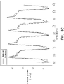
- the subject's arterial pulsatility is measured and a parameter is derived from the subject's arterial pulsatility.
- a parameter is derived from the subject's arterial pulsatility.
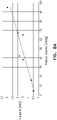
- the rotation rate of the impeller increases, the flow rate that is generated by the blood pump increases.
- flow that is generated by the blood pump is non-pulsatile, since the blood pump is a continuous-flow blood pump rather than a pulsatile blood pump.
- the subject's arterial pulsatility decreases.
- the subject's arterial pulsatility is measured as the rotation rate of the impeller changes.
- a relationship between the arterial pulsatility and the impeller rotation rate and/or the pump flow rate is derived.
- the subject's native cardiac output is derived.
- the relationship between the subject's arterial pulsatility and the pump flow rate is extrapolated to determine what the pump flow rate would be when the subject's arterial pulsatility reaches zero. It is hypothesized that, at this value, the blood pump is replacing the native function of the heart and that the flow rate that is generated by the pump at this value provides an approximation of the subject's native cardiac output.
- apparatus including: a blood pump configured to be placed inside a body of subject, the blood pump including:
- the impeller includes three helical elongate elements, such that the three helical elongate elements with the film of material coupled thereto defines three blades of the impeller, and a respective elongate element extends from the ring to each of the three helical elongate elements, such that there is a respective elongate element within each of the three blades of the impeller.
- the elongate elements are configured to not resist compression, and the elongate elements are configured to prevent the impeller from radially expanding by applying tensile force to the helical elongate elements.
- the film of material forms a continuous U-shaped curved surface, with the U-shaped curvature of the film of material being substantially unbroken at the axial structure.
- a pressure side of each of the blades of the impeller when viewed from a distal end of the impeller, is convex in a distal region of the impeller and is concave in a proximal region of the impeller.
- the pressure side of each of the blades of the impeller transforms to being substantially radially oriented in a region of the elongate element within the impeller blade.
- the helical elongate elements are coated with a coupling agent that is configured to enhance bonding between the helical elongate element and the film of material.
- the film of material includes an elastomeric material
- the coupling agent includes at least two functional groups that are configured to bond respectively with the helical elongate elements and with the elastomeric material.
- the coupling agent includes a silane compound.
- the apparatus further includes a layer of an elastomer disposed between the film of material and the coupling agent.
- the layer of the elastomer is configured to round the helical elongate elements.
- the film of material is made of the elastomer.
- the elastomer includes a polycarbonate-based thermoplastic polyurethane.
- the axial structure includes a spring.
- the spring includes a tube at an intermediate location along a length of the spring and the ring is disposed around the tube.
- coupling the elastomeric film to the at least one helical elongate element, such that the at least one helical elongate element with the elastomeric film coupled thereto defines a blade of the impeller includes dipping the helical elongate element into an elastomeric material from which the elastomeric film is made.
- the elastomeric film includes an elastic material having an ultimate elongation of more than 300 percent. In some applications, the elastomeric film includes an elastic material having a melt flow index of at least 4. In some applications, the elastomeric film includes an elastic material having an ultimate tensile strength of more than 6000 psi.
- coating the at least one helical elongate element with the coupling agent includes coating the at least one helical elongate element with a silane compound containing a first functional group which is configured to bond with the helical elongate element, and a second functional group which is configured to bond with the elastomeric layer.
- the elastomeric layer is made of a given elastomeric material and the elastomeric film is made of the given elastomeric material. In some applications, the elastomeric layer is made of a first elastomeric material and the elastomeric film is made of a second elastomeric material that is different from the first elastomeric material.
- coating the coated helical elongate element with the elastomeric layer includes spraying an elastomer onto the coated helical elongate element. In some applications, coating the coated helical elongate element with the elastomeric layer includes at least partially rounding the coated helical elongate element.
- coating the coated helical elongate element with the elastomeric layer includes coating the coated helical elongate element with the elastomeric layer within a given time period of coating the at least one helical elongate element with the coupling agent. In some applications, coating the coated helical elongate element with the elastomeric layer further includes spraying additional elastomeric material onto the coated helical elongate element subsequent to coating the coated helical elongate element with the elastomeric layer within the given time period of coating the at least one helical elongate element with the coupling agent.
- apparatus including: a ventricular assist device including:
- the set of sensors is additionally configured to measure a magnetic flux amplitude signal
- computer processor is configured to determine the physiological parameter of the subject at least partially based upon a combination of the magnetic flux amplitude signal and the detected magnetic phase difference.
- the computer processor is configured to determine a pressure difference between the subject's left ventricle and an aorta of the subject at least partially in response to the magnetic phase difference between the driven magnet and the drive magnet. In some applications, the computer processor is configured to determine left ventricular pressure of the subject at least partially in response to the magnetic phase difference between the driven magnet and the drive magnet. In some applications, the computer processor is configured to determine an event in a cardiac cycle of the subject at least partially in response to the magnetic phase difference between the driven magnet and the drive magnet.
- the set of sensors includes a first magnetometer configured to measure magnetic phase of the driven magnet, and a second magnetometer configured to measure magnetic phase of the driven magnet.
- the second magnetometer is configured to measure the magnetic phase of the driven magnet by measuring a magnetic phase of the motor.
- the computer processor is configured to receive a signal indicative of current consumption by the motor and is configured to determine the physiological parameter of the subject at least partially based upon a combination of the current consumption by the motor and the detected magnetic phase difference.
- the set of sensors is additionally configured to measure a magnetic flux amplitude signal, and computer processor is configured to determine the physiological parameter of the subject at least partially based upon a combination of the current consumption by the motor, the magnetic flux amplitude signal, and the detected magnetic phase difference.
- apparatus including:
- apparatus including: a left-ventricular assist device configured to assist left-ventricular functioning of a subject, the left-ventricular assist device including:
- the frame has a length of more than 25 mm.
- apparatus including: an impeller including:
- the axial structure includes a cylindrical axial structure. In some applications, the cylindrical axial structure includes a spring.
- apparatus including: a blood pump including:
- apparatus including: a blood pump including:
- apparatus including: a blood pump including:
- apparatus including: a blood pump including:
- apparatus including: a blood pump including:
- proximal and related terms when used with reference to a device or a portion thereof, should be interpreted to mean an end of the device or the portion thereof that, when inserted into a subject's body, is typically closer to a location through which the device is inserted into the subject's body.
- distal when used with reference to a device or a portion thereof, should be interpreted to mean an end of the device or the portion thereof that, when inserted into a subject's body, is typically further from the location through which the device is inserted into the subject's body.
- the scope of the present invention includes using the apparatus and methods described herein in anatomical locations other than the left ventricle and the aorta. Therefore, the ventricular assist device and/or portions thereof are sometimes referred to herein (in the specification and the claims) as a blood pump.
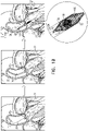
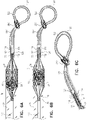
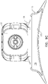
- FIGs. 1A , 1B , and 1C are schematic illustrations of a ventricular assist device 20, a distal end of which is configured to be disposed in a subject's left ventricle 22, in accordance with some applications of the present invention.
- Fig. 1A shows an overview of the ventricular assist device system including a control console 21, and a motor unit 23. (As described hereinbelow, the motor unit is typically a handle that houses a motor.)
- Fig. 1B shows the ventricular assist device being inserted into the subject's left ventricle, and Fig. 1C shows a pump portion 27 of the ventricular assist device in greater detail.
- the ventricular assist device includes a pump-outlet tube 24, which traverses an aortic valve 26 of the subject, such that a proximal end 28 of the pump-outlet tube is disposed in an aorta 30 of the subject and a distal end 32 of the pump-outlet tube is disposed within left ventricle 22.
- Pump-outlet tube 24 is typically an elongate tube, an axial length of the pump-outlet tube typically being substantially larger than its diameter.
- the scope of the present invention includes using the apparatus and methods described herein in anatomical locations other than the left ventricle and the aorta. Therefore, the ventricular assist device and/or portions thereof are sometimes referred to herein (in the specification and the claims) as a blood pump.
- the ventricular assist device is used to assist the functioning of a subject's left ventricle during a percutaneous coronary intervention.
- the ventricular assist device is typically used for a period of up to 10 hours (e.g., up to six hours), during a period in which there is risk of developing hemodynamic instability (e.g., during or immediately following the percutaneous coronary intervention).
- the ventricular assist device is used to assist the functioning of a subject's left ventricle for a longer period (e.g., for example, 2-20 days, e.g., 4-14 days) upon a patient suffering from cardiogenic shock, which may include any low-cardiac-output state (e.g., acute myocardial infarction, myocarditis, cardiomyopathy, post-partum, etc.).
- cardiogenic shock which may include any low-cardiac-output state (e.g., acute myocardial infarction, myocarditis, cardiomyopathy, post-partum, etc.).
- the ventricular assist device is used to assist the functioning of a subject's left ventricle for yet a longer period (e.g., several weeks or months), e.g., in a "bridge to recovery" treatment.
- the ventricular assist device is permanently or semi-permanently implanted, and the impeller of the ventricular assist device is powered transcutaneously, e.g.,
- Fig. 1B which shows steps in the deployment of the ventricular assist device in the left ventricle
- the distal end of the ventricular assist device is guided to the left ventricle over a guidewire 10.
- a delivery catheter 143 is disposed over the distal end of the device.
- the delivery catheter is typically retracted to the aorta, and the guidewire is withdrawn from the subject's body. The retraction of the delivery catheter typically causes self-expandable components of the distal end of the device to assume non-radially-constrained configurations, as described in further detail hereinbelow.
- the ventricular assist device is inserted into the subject's body in order to provide an acute treatment to the subject.
- the delivery catheter is advanced over the distal end of the device, which causes the self-expandable components of the distal end of the device to assume radially-constrained configurations.
- the distal end of the device is retracted into the delivery catheter which causes the self-expandable components of the distal end of the device to assume radially-constrained configurations.
- the ventricular assist device and/or delivery catheter 143 includes an ultrasound transducer at its distal end and the ventricular assist device is advanced toward the subject's ventricle under ultrasound guidance.
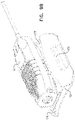
- an impeller 50 is disposed within a distal section 102 of pump-outlet tube 24 and is configured to pump blood from the left ventricle into the aorta by rotating.
- the pump-outlet tube typically defines one or more blood inlet openings 108 at the distal end 32 of the pump-outlet tube, via which blood flows into the pump-outlet tube from the left ventricle, during operation of the impeller.
- proximal section 106 of the pump-outlet tube defines one or more blood outlet openings 109, via which blood flows from the pump-outlet tube into the ascending aorta, during operation of the impeller.
- control console 21 which typically includes a computer processor 25, controls impeller rotation.
- the computer processor may control a motor 74 (shown in Fig. 7A , for example), which is disposed within motor unit 23 (shown in Fig. 1A ) and which drives the impeller to rotate via a drive cable 130 (shown in Fig. 7A , for example).
- the computer processor is configured to detect a physiological parameter of the subject (such as left-ventricular pressure, cardiac afterload, rate of change of left-ventricular pressure, etc.) and to control rotation of the impeller in response thereto, as described in further detail hereinbelow.
- Computer processor 25 is typically a hardware device programmed with computer program instructions to produce a special-purpose computer.
- computer processor 25 when programmed to perform the techniques described herein, computer processor 25 typically acts as a special-purpose, ventricular-assist computer processor and/or a special-purpose, blood-pump computer processor.
- a purging system 29 (shown in Fig. 1A ) drives a fluid (e.g., a glucose solution) to pass through portions of ventricular assist device 20, for example, in order to cool portions of the device and/or in order to wash debris from portions of the device.
- a fluid e.g., a glucose solution
- Purging system 29 is described in further detail hereinbelow.
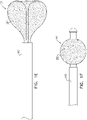
- a frame 34 is disposed within the pump-outlet tube around impeller 50.
- the frame is typically made of a shape-memory alloy, such as nitinol.
- the shape-memory alloy of the frame is shape set such that at least a portion of the frame (and thereby distal section 102 of tube 24) assumes a generally circular, elliptical, or polygonal cross-sectional shape in the absence of any forces being applied to distal section 102 of tube 24.
- the frame is configured to hold the distal portion of the pump-outlet tube in an open state.
- the distal portion of the pump-outlet tube is configured to be placed within the subject's body, such that the distal portion of the pump-outlet tube is disposed at least partially within the left ventricle.
- Pump-outlet tube 24 is typically made of a blood-impermeable collapsible material.
- pump-outlet tube 24 may include polyurethane, polyester, and/or silicone.
- the pump-outlet tube is made of polyethylene terephthalate (PET) and/or polyether block amide (e.g., PEBAX ® ).
- the pump-outlet tube is reinforced with a reinforcement structure, e.g., a braided reinforcement structure, such as a braided nitinol tube.
- a reinforcement structure e.g., a braided reinforcement structure, such as a braided nitinol tube.
- the proximal portion of the pump-outlet tube is configured to be placed such that it is at least partially disposed within the subject's ascending aorta.
- the proximal portion of the pump-outlet tube traverses the subject's aortic valve, passing from the subject's left ventricle into the subject's ascending aorta, as shown in Fig. 1B .
- the pump-outlet tube typically defines one or more blood inlet openings 108 at the distal end of the pump-outlet tube, via which blood flows into the pump-outlet tube from the left ventricle, during operation of the impeller.
- the proximal portion of the pump-outlet tube defines one or more blood outlet openings 109, via which blood flows from the pump-outlet tube into the ascending aorta, during operation of the impeller.
- the pump-outlet tube defines a plurality of blood outlet openings 109, for example, between two and eight blood outlet openings (e.g., between two and four blood outlet openings).
- the pressure of the blood flow through the pump-outlet tube typically maintains the proximal portion of the tube in an open state.
- the proximal portion of the pump-outlet tube is configured to collapse inwardly, in response to pressure outside of the proximal portion of the pump-outlet tube exceeding pressure inside the proximal portion of the pump-outlet tube. In this manner, the proximal portion of the pump-outlet tube acts as a safety valve, preventing retrograde blood flow into the left ventricle from the aorta.
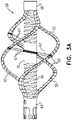
- frame 34 is shaped such that the frame defines a proximal conical portion 36, a central cylindrical portion 38, and a distal conical portion 40.
- proximal conical portion is such that the narrow end of the cone is proximal with respect to the wide end of the cone.
- distal conical portion is such that the narrow end of the cone is distal with respect to the wide end of the cone.
- pump-outlet tube 24 extends to the distal end of cylindrical portion 38 (or slightly proximal or distal thereof), such that the distal end of the pump-outlet tube defines a single axially-facing blood inlet opening 108, as shown in Fig. 1C .
- an inner lining 39 lines the frame, as described hereinbelow with reference to Figs. 12A-B .
- the inner lining partially overlaps or fully overlaps with pump-outlet tube 24 over the portion of the frame that the inner lining lines.
- the distal end of the inner lining defines a single axially-facing blood inlet opening 108.
- the pump-outlet tube and the inner lining both terminate before the distal end of the cylindrical portion of the frame, such that a distal part of the cylindrical portion of the frame is uncovered, as described hereinbelow with reference to Fig. 13 .
- pump-outlet tube 24 includes a conical proximal portion 42 and a cylindrical central portion 44.
- conical proximal portion 36 is disposed entirely within proximal section 106 described hereinabove, and the cylindrical central portion typically extends from within proximal section 106 to distal section 102.
- the proximal conical portion is typically such that the narrow end of the cone is proximal with respect to the wide end of the cone.
- blood outlet openings 109 are defined by pump-outlet tube 24, such that the openings extend at least partially along proximal conical portion 42 of tube 24.
- the blood outlet openings are teardrop-shaped, as shown in Fig. 1C .
- the teardrop-shaped nature of the blood outlet openings in combination with the openings extending at least partially along the proximal conical section of tube 24 causes blood to flow out of the blood outlet openings along flow lines that are substantially parallel with the longitudinal axis of tube 24 at the location of the blood outlet openings.
- the diameter of pump-outlet tube 24 changes along the length of the central portion of the pump-outlet tube, such that the central portion of the pump-outlet tube has a frustoconical shape.
- the central portion of the pump-outlet tube may widen from its proximal end to is distal end, or may narrow from its proximal end to its distal end.
- the central portion of the pump-outlet tube has a diameter of between 5 and 7mm, and at its distal end, the central portion of the pump-outlet tube has a diameter of between 8 and 12 mm.
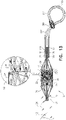
- the ventricular assist device typically includes a distal-tip element 107 that is disposed distally with respect to frame 34 and that includes an axial-shaft-receiving tube 126 and a distal-tip portion 120, both of which are described in further detail hereinbelow.
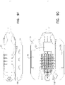
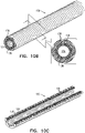
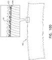
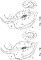
- Fig. 1D is a schematic illustration of ventricular assist device 20, in which pump-outlet tube 24 extends to the end of distal conical portion 40 of the frame, and the pump-outlet tube defines a plurality of lateral blood inlet openings 108, in accordance with some applications of the present invention.
- the pump-outlet tube typically defines a distal conical portion 46, with the narrow end of the cone being distal with respect to the wide end of the cone.
- the pump-outlet tube defines two to four lateral blood inlet openings.
- each of the blood inlet openings 108 defines an area of more than 20 square mm (e.g., more than 30 square mm), and/or less than 60 square mm (e.g., less than 50 square mm), e.g., 20-60 square mm, or 30-50 square mm.
- the outlet tube defines a greater number of smaller blood inlet openings (not shown), e.g., more than 10 small blood inlet openings, more than 50 small blood inlet openings, more than 100 small blood inlet openings, or more than 150 small blood inlet openings, e.g., 50-100 small blood inlet openings, 100-150 small blood inlet openings, or 150-200 small blood inlet openings.
- each of the small blood inlet openings defines an area of more than 0.1 square mm (e.g., more than 0.3 square mm), and/or less than 5 square mm (e.g., less than 1 square mm), e.g., 0.1-5 square mm, 0.2-0.5 square mm, or 0.3-1 square mm.
- distal conical portion 46 of the pump-outlet tube is configured to reduce a risk of structures from the left ventricle (such as chordae tendineae, trabeculae carneae, and/or papillary muscles) entering into the frame and potentially being damaged by the impeller and/or an axial shaft upon which the impeller is mounted, and/or causing damage to the left ventricular assist device. Therefore, for some applications, the small blood-inlet openings are shaped such that in at least one direction the widths (or spans) of the openings are less than 1 mm, e.g., 0.1-1 mm, or 0.3-0.8 mm.
- the small blood inlet openings define generally rectangular (or elliptical) shapes.
- the ratio of the lengths to the widths of the small blood inlet openings is between 1.1:1 and 4:1, e.g., between 3:2 and 5:2.
- the small blood-inlet openings are configured (a) to block structures from the left ventricle (such as chordae tendineae, trabeculae carneae, and/or papillary muscles) from entering into the frame, but (b) to provide the portion of the pump-outlet tube that defines the small blood inlet openings with a relatively high porosity.
- the portion of the pump-outlet tube that defines the small blood inlet openings has a porosity of more than 40 percent, e.g., more than 50 percent (where porosity is defined as the percentage of the area of this portion that is porous to blood flow).
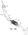
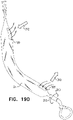
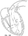
- Figs. 1E and 1F are schematic illustrations of ventricular assist device 20, the ventricular assist device that includes a braided structure 260 and/or a mesh 282 in a distal region of the device, the braided structure and/or mesh being configured to separate blood-inlet openings of the ventricular assist device from internal structures of the ventricle, in accordance with some applications of the present invention.
- Braided structure 260 is typically generally similar to braided structure 260 described with respect to Fig. 20B of US 2019/0209758 to Tuval , which is incorporated herein by reference.
- Mesh 282 is generally similar to mesh 282 described with respect to Fig. 21D of US 2019/0209758 to Tuval , which is incorporated herein by reference.
- braided structure 260 e.g., a braided metal or alloy, such as a shape-memory alloy (e.g., nitinol)
- the braided material may be disposed at the distal end of the device.
- the device may include distal-tip element 107 (which is typically as described with reference to Figs. 14-16B ), and the braided material is disposed around a portion of the device, such as to cover a portion of the distal-tip element.
- the braided material is disposed over at least a portion of frame 34.
- the braided material may surround a portion of the frame extending distally from at least a longitudinal location along the frame at which blood-outlet tube 24 ends and/or at which inner lining 39 ends until a distal end of the frame.
- the braided structure is disposed such as to cover blood-inlet openings 108.
- the outer surface of distal-tip element 107 includes a radially-expandable mesh 282, which is configured to self-expand when distal-tip element 107 is disposed inside the subject's left ventricle.
- the device includes a distal-tip element that is generally as described with reference to Figs. 14-16B , and the mesh is disposed around a portion of the device, such as to cover a portion of the distal-tip element.
- the mesh is disposed over at least a portion of frame 34.
- the mesh may surround a portion of the frame extending distally from at least a longitudinal location along the frame at which blood-outlet tube 24 ends and/or at which inner lining 39 ends until a distal end of the frame.
- the mesh is disposed such as to cover blood-inlet openings 108.
- braided structure 260 and/or mesh 282 separates the one or more blood inlet openings 108 from inner structures of the left ventricle in three dimensions. In this manner, braided structure 260 and/or mesh 282 separates one or more blood inlet openings 108 from the interventricular septum, chordae tendineae, papillary muscles, trabeculae carneae, and/or the apex of the left ventricle.
- cells of frame 34 in the vicinity of blood inlet openings 108 are configured to define openings that are smaller than those in other portions of the frame.
- the cells in the distal conical portion of the frame may define openings that are smaller than openings defined by cells in the proximal conical portion of the frame.
- the cells in the distal conical portion of the frame may define openings that are smaller than openings defined by cells in the cylindrical portion of the frame.
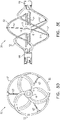
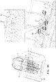
- Fig. 2 is a schematic illustration of frame 34 that houses an impeller of ventricular assist device 20, in accordance with some applications of the present invention.
- frame 34 is typically made of a shape-memory alloy, such as nitinol, and the shape-memory alloy of the frame is shape set such that the frame (and thereby tube 24) assumes a generally circular, elliptical, or polygonal cross-sectional shape in the absence of any forces being applied to pump-outlet tube 24 and/or frame 34.
- the frame is configured to hold the distal portion of the tube in an open state.
- the frame is a stent-like frame, in that it comprises struts that, in turn, define cells. Further typically, the frame is covered with pump-outlet tube 24, and/or covered with an inner lining 39, described hereinbelow, with reference to Figs. 12A-B . As described hereinbelow, for some applications impeller 50 undergoes axial back-and-forth motion with respect to frame 34. Typically, over the course of the motion of the impeller with respect to the frame the location of the portion of the impeller that defines the maximum span of the impeller is disposed within cylindrical portion 38 of frame 34.
- pump-outlet tube 24, and/or inner lining 39 gets stretched between edges of the cells, such that the pump-outlet tube 24, and/or inner lining 39 does not define a circular cross-section.
- this occurs in the region in which the portion of the impeller that defines the maximum span of the impeller is disposed, this results in a non-constant gap between the edges of the impeller blades and tube 24 (and/or inner lining) at that location, over the course of a rotation cycle of the impeller.
- this may lead to increased hemolysis relative to if there were a constant gap between the edges of the impeller blades and tube 24 (and/or inner lining) at that location, over the course of the rotation cycle of the impeller.
- the frame defines a large number of relatively small cells.
- the maximum cell width CW of the each of the cells i.e., the distance from the inner edge of the strut at the central junction on one side of the cell to the inner edge of the strut at the central junction on the other side of the cell, as measured around the circumference of cylindrical portion 38
- the pump-outlet tube 24 (and/or inner lining) defines a substantially circular cross-section within the cylindrical portion of the frame.
- the frame defines the following portions (a) coupling portion 31 via which the frame is coupled to a proximal bearing 116 (shown in Fig. 4 ) of the ventricular assist device, (b) proximal conical portion 36, (c) cylindrical portion 38, (d) distal conical portion 40, and (e) distal strut junctions 33.
- struts 37 of the frame pass through junctions 35, at which the two struts branch from a single strut, in a Y-shape.
- typically frame 34 is placed in a radially-constrained (i.e., crimped) configuration within delivery catheter 143 by the frame being axially elongated.
- the frame typically transmits its radial narrowing to the impeller, and the impeller becomes radially constrained by becoming axially elongated within the frame.
- the struts of the frame being configured in the manner described above facilitates transmission of axial elongation from the delivery catheter (or other device that is configured to crimp the frame) to the frame, which in turn facilitates transmission of axial elongation to the impeller.
- the pairs of struts that branch from each of junctions 35 are configured to pivot about the junction and move closer to each other such as to close.
- distal strut junctions 33 are not circumferentially connected and are typically configured to be maintained in open states when the frame is coupled to axial shaft 92 (shown in Fig. 4 ), in order for the impeller to be placed within the frame via the distal end of the frame. Subsequently, the distal strut portions are closed around the outside of a distal bearing 118, as described in further detail hereinbelow with reference to Figs. 5A-B . For some applications, a proximal end of distal-tip element 107 (shown in Fig. 1C ) holds the distal strut portions in their closed configurations around the outside of distal bearing 118.
- frame 34 when disposed in its non-radially constrained configuration, has a total length of more than 25 mm (e.g., more than 30 mm), and/or less than 50 mm (e.g., less than 45 mm), e.g., 25-50 mm, or 30-45 mm.
- the length of the frame increases by between 2 and 5 mm.
- the cylindrical portion of frame 34 when disposed in its non-radially constrained configuration, has a length of more than 10 mm (e.g., more than 12 mm), and/or less than 25 mm (e.g., less than 20 mm), e.g., 10-25 mm, or 12-20 mm.
- a ratio of the length of the cylindrical portion of the frame to the total length of the frame is more than 1:4 and/or less than 1:2, e.g., between 1:4 and 1:2.
- Figs. 3A-C are schematic illustrations of impeller 50 or portions thereof, in accordance with some applications of the present invention.
- the impeller includes at least one outer helical elongate element 52, which winds around a central axial spring 54, such that the helix defined by the helical elongate element is coaxial with the central axial spring.
- typically central axial spring includes a tube 70 at an intermediate location along its length.
- the scope of the present application includes using other axial structure in place of a spring.
- the impeller includes two or more helical elongate elements (e.g., three helical elongate elements, as shown in Figs. 3A-C ).
- the helical elongate elements and the central axial spring are made of a shape-memory material, e.g., a shape-memory alloy such as nitinol.
- each of the helical elongate elements and the central axial spring support a film 56 of a material (e.g., an elastomer, such as polyurethane, and/or silicone) therebetween.
- the film of material includes pieces of nitinol embedded therein, for example in order to strengthen the film of material.
- the impeller is shown in the absence of the film of material in Fig. 3A .
- Figs. 3B and 3C show respective views of the impeller with the film of material supported between the helical elongate elements and the spring.
- Each of the helical elongate elements together with the film extending from the helical elongate element to the spring, defines a respective impeller blade, with the helical elongate elements defining the outer edges of the blades, and the axial spring defining the axis of the impeller.
- the film of material extends along and coats the spring.
- sutures 53 e.g., polyester sutures, shown in Figs. 3B and 3C
- sutures 53 are wound around the helical elongate elements, e.g., as described in US 10,864,310 to Schwammenthal , which is incorporated herein by reference.
- the sutures are configured to facilitate bonding between the film of material (which is typically an elastomer, such as polyurethane, or silicone) and the helical elongate element (which is typically a shape-memory alloy, such as nitinol).
- sutures e.g., polyester sutures, not shown
- the sutures are configured to facilitate bonding between the film of material (which is typically an elastomer, such as polyurethane, or silicone) and the spring (which is typically a shape-memory alloy, such as nitinol).
- Enlargements A and B of Fig. 3C show two alternative ways in which the sutures are tied around helical elongate elements 52.
- the sutures are tied around the outer surface of the helical elongate elements, as shown in enlargement A.
- the helical elongate elements define grooves 45 on their outer surfaces, and the sutures are embedded within the grooves, as shown in enlargement B.
- the sutures typically do not add to the outer profile of the impeller, and the outer profile of the impeller is defined by the outer surfaces of the helical elongate elements.
- proximal ends of spring 54 and helical elongate elements 52 extend from a proximal bushing (i.e., sleeve bearing) 64 of the impeller, such that the proximal ends of spring 54 and helical elongate elements 52 are disposed at approximately the same point and have a similar radial distance from the longitudinal axis of the impeller.
- distal ends of spring 54 and helical elongate elements 52 extend from a distal bushing 58 of the impeller, such that the distal ends of spring 54 and helical elongate elements 52 are disposed at approximately the same point and have a similar radial distance from the longitudinal axis of the impeller.
- spring 54, as well as proximal bushing 64 and distal bushing 58 of the impeller define a lumen therethrough, such that the impeller defines a continuous lumen 62 therethrough (shown in Fig. 3C ).
- Fig. 4 is a schematic illustration of impeller 50 disposed inside frame 34 of ventricular assist device 20, in accordance with some applications of the present invention.
- an inner lining 39 lines the frame, as described hereinbelow with reference to Figs. 12A-B .
- the inner lining partially overlaps or fully overlaps with pump-outlet tube 24 over the portion of the frame that the inner lining lines.
- the pump-outlet tube and the inner lining both terminate before the distal end of cylindrical portion 38 of the frame, such that a distal part of the cylindrical portion of the frame is uncovered, as described hereinbelow with reference to Fig. 13 .
- the pump-outlet tube continues to cover the distal conical portion of the frame, as described with reference to Fig. 1D .
- the inner lining lines the inside of the cylindrical portion of the frame and pump-outlet tube 24 does not cover the cylindrical portion of the frame.
- the scope of the present application includes applying the apparatus and methods described with reference to Fig. 4 to any one of the applications described hereinbelow with reference to Figs. 1D , 12A-B or Fig. 13 .
- a gap G typically there is a gap G, between the outer edge of impeller 50 and inner lining 39, even at a location at which the span of the impeller is at its maximum.
- the gap between the outer edge of the blade of the impeller and the inner lining 39 be relatively small, in order for the impeller to efficiently pump blood from the subject's left ventricle into the subject's aorta.
- a gap between the outer edge of the blade of the impeller and the inner surface of frame 34 be maintained substantially constant throughout the rotation of the impeller within frame 34, for example, in order to reduce the risk of hemolysis.
- gap G between the outer edge of the impeller and the inner lining 39, at the location at which the span of the impeller is at its maximum is greater than 0.05 mm (e.g., greater than 0.1 mm), and/or less than 1 mm (e.g., less than 0.4 mm), e.g., 0.05-1 mm, or 0.1-0.4 mm.
- the outer diameter of the impeller at the location at which the outer diameter of the impeller is at its maximum is more than 7 mm (e.g., more than 8 mm), and/or less than 10 mm (e.g., less than 9 mm), e.g., 7-10 mm, or 8-9 mm.
- the inner diameter of frame 34 (as measured from the inside of inner lining 39 on one side of the frame to the inside of inner lining on the opposite side of the frame) is greater than 7.5 mm (e.g., greater than 8.5 mm), and/or less than 10.5 mm (e.g., less than 9.5 mm), e.g., 7.5-10.5 mm, or 8.5-9.5 mm.
- the outer diameter of frame 34 is greater than 8 mm (e.g., greater than 9 mm), and/or less than 13 mm (e.g., less than 12 mm), e.g., 8-13 mm, or 9-12 mm.
- an axial shaft 92 passes through the axis of impeller 50, via lumen 62 of the impeller.
- the axial shaft is rigid, e.g., a rigid tube.
- a portion of the axial shaft is at least partially flexible, e.g., as described with reference to Figs. 20A-C .
- proximal bushing 64 of the impeller is coupled to the shaft such that the axial position of the proximal bushing with respect to the shaft is fixed, and distal bushing 58 of the impeller is slidable with respect to the shaft.
- the axial shaft itself is radially stabilized via a proximal radial bearing 116 and a distal radial bearing 118.
- the axial shaft by passing through lumen 62 defined by the impeller, radially stabilizes the impeller with respect to the inner surface of frame 34, such that even a relatively small gap between the outer edge of the blade of the impeller and the inner surface of frame 34 (e.g., a gap that is as described above) is maintained, during rotation of the impeller.
- the impeller includes a plurality of elongate elements 67 extending radially from central axial spring 54 to outer helical elongate elements 52.
- Elongate elements 67 are typically flexible but are substantially non-stretchable along the axis defined by elongate elements 67. Further typically, each of elongate elements 67 is configured to substantially not resist compression.
- each elongate element 67 is configured to exert a tensile force upon helical elongate element 52 that prevents helical elongate element 52 from moving radially outward, such that (in the absence of elongate element 67) a separation between helical elongate element 52 and central axial spring 54 would be greater than a length of elongate element 67.
- elongate elements 67 may include strings (such as polyester, and/or another polymer or a natural material that contains fibers) and/or wires (such as nitinol wires, and/or wires made of a different alloy, or a metal). In this manner, the elongate elements prevent the impeller from radially expanding by applying tensile force to the helical elongate elements.
- elongate elements 67 maintain helical elongate element 52 (which defines the outer edge of the impeller blade) within a given distance with respect to central axial spring 54. In this manner, elongate elements 67 are configured to prevent the outer edge of the impeller from being forced radially outward due to forces exerted upon the impeller during the rotation of the impeller. In other words, elongate elements 67 act as impeller-expansion-prevention elements. Elongate elements 67 are thereby configured to maintain the gap between the outer edge of the blade of the impeller and the inner surface of frame 34, during rotation of the impeller.
- more than one (e.g., more than two) and/or fewer than eight (e.g., fewer than four) elongate elements 67 are used in the impeller, with each of elongate elements 67 typically being doubled (i.e., extending radially from central axial spring 54 to an outer edge of helical elongate element 52, and then returning from the helical elongate element back to the central axial spring).
- a plurality of elongate elements 67, each of which extends from the spring to a respective helical elongate element 52 and back to central axial spring 54, are formed from a single piece of string or a single wire.
- the impeller is manufactured in the following manner.
- Proximal bushing 64, distal bushing 58, and helical elongate elements 52 are cut from a tube of shape-memory material, such as nitinol.
- the cutting of the tube, as well as the shape setting of the shape-memory material, is typically performed such that the helical elongate elements and the bushings are defined by a tube of shape-memory material that is cut and shape set, e.g., using generally similar techniques to those described in US 10,039,874 to Schwammenthal .
- spring 54 is inserted into the cut and shape-set tube, such that the spring extends along the length of the tube from at least the proximal bushing to the distal bushing.
- the spring is inserted into the cut and shape-set tube while the spring is in an axially compressed state, and the spring is configured to be held in position with respect to the tube, by exerting a radial force upon the proximal and distal bushings.
- portions of the spring are welded to the proximal and distal bushings.
- the spring is cut from a tube of a shape-memory material, such as nitinol.
- the spring is configured such that, when the spring is disposed in a non-radially-constrained configuration (in which the spring is typically disposed during operation of the impeller), there are substantially no gaps between windings of the spring and adjacent windings thereto.
- elongate elements 67 are placed such as to extend between the spring and one or more of helical elongate elements 52, for example, in the following manner.
- a mandrel e.g., a polyether ether ketone (PEEK) and/or a polytetrafluoroethylene (PTFE) mandrel
- PEEK polyether ether ketone
- PTFE polytetrafluoroethylene
- a string or a wire is then threaded such that it passes (a) from the mandrel to a first one of the helical elongate elements 52, (b) back from the first of the helical elongate elements 52 to the mandrel, (c) around the mandrel, and to a second one of the helical elongate elements 52, (d) back from the second one of the helical elongate elements 52 to the mandrel, etc.
- the ends of the string or the wire are coupled to each other, e.g., by tying them to each other.
- each string or wire passes from the helical elongate element around the mandrel and back to the helical elongate element, with the two ends of the string being tied to each other.
- the spring is shaped to define a tube 70 (i.e., at this location the spring does not define windings), as shown, and the string or the wire is wound around the tube.
- the string or the wire is not wound around the tube, and does not cross the longitudinal axis of the impeller. Rather, the string or the wire is secured with respect to tube 70 via a securing element 75 (such as a ring), as described in further detail hereinbelow with reference to Fig. 3F .
- sutures 53 are wound around helical elongate elements 52, in order to facilitate bonding between the film of material (which is typically an elastomer, such as polyurethane, or silicone) and helical elongate elements 52 (which is typically a shape-memory alloy, such as nitinol), in a subsequent stage of the manufacture of the impeller.
- sutures e.g., polyester sutures, not shown
- spring 54 are wound around spring 54.
- the sutures are configured to facilitate bonding between the film of material (which is typically an elastomer, such as polyurethane, or silicone) and the spring (which is typically a shape-memory alloy, such as nitinol), in the subsequent stage of the manufacture of the impeller.
- the film of material which is typically an elastomer, such as polyurethane, or silicone
- the spring which is typically a shape-memory alloy, such as nitinol
- a structure 59 has been assembled that is as shown in Fig. 3A .
- the structure includes the cut and shape-set tube that defines the proximal and distal bushings, the helical elongate elements, and the spring (and, optionally, the elongate elements, and the sutures).
- This structure is dipped into the material that defines film 56.
- the assembled structure is dipped into the material with the mandrel disposed through the lumen defined by the spring and the bushings, although it is noted that the mandrel is not shown in Fig. 3A .
- the material from which the film is made is silicone and/or polyurethane (and/or a similar elastomer), and the assembled structure is dipped into the material, while the material is in an uncured, liquid state. Subsequently, the material is cured such that it solidifies, e.g., by being left to dry. For some applications, while the material is drying the assembled structure is rotated, which typically facilitates the formation of a film of material having a substantially uniform thickness within each of the impeller blades. Once the material has dried, the mandrel is typically removed from the lumen defined by the bushings and the spring.
- the result of the process described above is typically that there is a continuous film of material extending between each of the helical elongate elements to the spring, and also extending along the length of the spring, such as to define a tube, with the spring embedded within the tube.
- the portions of the film that extend from each of the helical elongate elements to the spring define the impeller blades.
- the impeller includes elongate elements 67, the elongate elements are typically embedded within these portions of film.
- elongate elements 67 are configured to limit the radial expansion of the blades of the impeller, as described in detail hereinabove.
- the span to which the elongate elements allow the impeller blades to expand is set using the following technique.
- the two ends of the string or the wire within respective blades are tied to each other.
- the ends of the string or the wire in each of the blade are tied such that the spans of the impeller blades are set to less than the span of the impeller that is desired, and such that there is some slack in the knots via which the two ends of the strings or the wires are tied to each other.
- the outer edges of the impeller blades are pulled apart from each other, such as to increase the spans of the impeller blades, by tightening the knots between the ends of the strings or the wires within the respective blades.
- the process is repeated and the spans of the impeller blades are measured, until the desired span of the impeller blades has been achieved.
- structure 59 with the string or wires tied thereto is dipped in an elastomeric material from which film 56 is made, and the elastomeric material is allowed to dry, such that the strings or the wires are maintained with the ends tied to each other at the desired span of the impeller blades.
- impeller 50 is inserted into the left ventricle transcatheterally, while impeller 50 is in a radially-constrained configuration.
- both helical elongate elements 52 and central axial spring 54 become axially elongated, and radially constrained.
- film 56 of the material e.g., silicone and/or polyurethane
- film 56 of the material changes shape to conform to the shape changes of the helical elongate elements and the central axial spring, both of which support the film of material.
- using a spring to support the inner edge of the film allows the film to change shape without the film becoming broken or collapsing, due to the spring providing a large surface area to which the inner edge of the film bonds.
- using a spring to support the inner edge of the film reduces a diameter to which the impeller can be radially constrained, relative to if, for example, a rigid shaft were to be used to support the inner edge of the film, since the diameter of the spring itself can be reduced by axially elongating the spring.
- proximal bushing 64 of impeller 50 is coupled to axial shaft 92 such that the axial position of the proximal bushing with respect to the shaft is fixed, and distal bushing 58 of the impeller is slidable with respect to the shaft.
- the impeller when the impeller is radially constrained for the purpose of inserting the impeller into the ventricle or for the purpose of withdrawing the impeller from the subject's body, the impeller axially elongates by the distal bushing sliding along the axial shaft distally. Subsequent to being released inside the subject's body, the impeller assumes its non-radially-constrained configuration (in which the impeller is typically disposed during operation of the impeller), as shown in Figs. 3A-C .
- impeller 50 is shown without including all of the features of the impeller as shown and described with respect to Figs. 3A-C .
- some of the figures show the impeller not including sutures 53 and/or elongate elements 67.
- the scope of the present application includes using an impeller with any of the features shown and described with respect to Figs. 3A-C in combination with any of the apparatus and methods described herein.
- the following technique is used to enhance bonding of the elastomeric material to the at least one helical elongate element in a manner that does not cause a protrusion from the effective edge of the impeller blade.
- the helical elongate elements Prior to being dipped in the elastomeric material, the helical elongate elements are coated with a coupling agent.
- a coupling agent is selected that has at least two functional groups that are configured to bond respectively with the helical elongate elements and with the elastomeric material.
- a silane compound such as n-(2-aminoethyl)-3-aminopropyltrimethoxysilane, may be used, with the silane compound containing a first functional group (e.g., (OH)) which is configured to bond with the helical elongate elements (which are typically made of an alloy, such a nitinol), and the silane compound containing a second functional group (e.g., (NH2)) which is configured to bond with the elastomeric material.
- a first functional group e.g., (OH)
- the silane compound containing a second functional group e.g., (NH2)
- the functional groups in the coupling agent are only active for a given time period (e.g., approximately an hour or less).
- a coat of elastomeric material is applied around the helical elongate elements.
- the coat of elastomeric material is the same elastomeric material or a similar elastomeric material to that used in film 56.
- a polycarbonate-based thermoplastic polyurethane such as Aromatic Carbothane TM (e.g., Aromatic Carbothane TM 75A) may be used in film 56, and the coating may be the same polycarbonate-based thermoplastic polyurethane, or a similar polycarbonate-based thermoplastic polyurethane, such as Pellethane ® (e.g., Pellethane ® 90A).
- the coated helical elongate elements are sprayed with a further layer of an elastomeric material.
- the elastomeric material that is sprayed is the same elastomeric material or a similar elastomeric material to that used as film 56.
- a polycarbonate-based thermoplastic polyurethane such as Aromatic Carbothane TM (e.g., Aromatic Carbothane TM 75A) may be used as film 56, and the sprayed material may be the same polycarbonate-based thermoplastic polyurethane, or a similar polycarbonate-based thermoplastic polyurethane, such as Pellethane ® (e.g., Pellethane ® 90A).
- applying the spray to the helical elongate elements rounds the helical elongate elements.
- the helical elongate element has a rounded cross section
- the elastomeric material forms a layer having a substantially uniform thickness at the interface with the helical elongate element.
- the step of applying the coat of elastomeric material as described in the previous paragraph, at least partially rounds the helical elongate elements.
- structure 59 is dipped in the elastomer from which film 56 is made, e.g., as described hereinabove.
- the material from which the film is made is an elastic material having an ultimate elongation of more than 300 percent, e.g., more than 400 percent.
- the material has a relatively low molecular weight.
- the material has a melt flow index (which is an indirect measure of molecular weight) of at least 4, e.g., at least 4.3.
- the material has an ultimate tensile strength of more than 6000 psi, e.g., more than 7000 psi, or more than 7500 psi.
- the material is a thermoplastic polyurethane, e.g., a Carbothane TM .
- Aromatic Carbothane TM 75 A is used.
- such materials combine one or more of the following properties: no outer diameter loss caused during the dip process, resistance to fatigue, resistance to becoming misshaped by being crimped, and low outer diameter loss during crimping.
- the scope of the present invention includes any technique whereby, prior to the helical elongate elements being dipped into the elastomeric material from which film 56 is made, additional layers of the same elastomeric material, a different elastomeric material, and/or a mediating material are applied to the helical elongate elements, whether by spraying, dipping, or a different coating method.
- additional layers of elastomeric material are configured to round the helical elongate elements, and/or to act as mediators to enhance bonding between the helical elongate elements and film 56 of material.
- a mediating material (such as silane) is configured to act as a mediator to enhance bonding between the helical elongate elements and film 56 of material.
- Figs. 3D and 3E are schematic illustrations of impeller 50, the impeller including a single integrated impeller-overexpansion-prevention element 72 that defines a plurality of elongate elements 67, in accordance with some applications of the present invention.
- Figs. 3D and 3E show the impeller in the absence of the film 56 of material, for illustrative purposes.
- element 72 defines a ring 73 and the plurality of elongate elements 67 extending radially from the ring.
- ring 73 of element 72 is placed around the spring, e.g., by being placed around tube 70, which is typically disposed at the longitudinally-central location of the spring.
- the ends of respective elongate elements 67 are then coupled to respective helical elongate elements 52.
- elongate elements 67 are typically flexible but are substantially non-stretchable along the axis defined by the elongate elements. Further typically, each of elongate elements 67 is configured to substantially not resist compression.
- each elongate element 67 is configured to exert a tensile force upon helical elongate element 52 that prevents helical elongate element 52 from moving radially outward, such that (in the absence of elongate element 67) a separation between helical elongate element 52 and central axial spring 54 would be greater than a length of elongate element 67.
- the impeller-overexpansion-prevention element is configured to prevent radial expansion of the impeller.
- a respective elongate element 67 is disposed within each one of the impeller blades and is configured to prevent the impeller blade from radially expanding.
- element 72 is made of polyester, and/or another polymer or a natural material that contains fibers, and/or nitinol (or a similar shape-memory alloy).
- the scope of the present application includes using single integrated impeller-overexpansion-prevention element 72 with an impeller having a different construction from that shown in Figs. 3D-E .
- the single integrated impeller-overexpansion-prevention element 72 could be used with an impeller having a differently constructed axial structure than spring 54.
- the axial structure defines a lumen therethrough, such that the impeller defines lumen 62 therethrough.
- Fig. 3F is a schematic illustration of impeller 50, the impeller including a securing element 75 that is configured to secure elongate elements 67 with respect to tube 70, in accordance with some applications of the present invention.
- the string or the wire that comprises elongate element 67 is not wound around tube 70, and does not cross the longitudinal axis of the impeller. Rather, the string or the wire is secured with respect to tube 70 via securing element 75.
- the string or the wire is secured to the outer surface of tube 70 at a location on the outer surface of the tube that is closest to the maximum span of the helical elongate element to which the ends of the string or the wire are tied.
- the securing element comprises a ring, as shown.
- the ring define small notches (or eyelets) 80 through which the string or the wire passes between the ring and tube 70.
- Figs. 3Gi and 3Gii are photographs of impeller 50, in accordance with some applications of the present invention.
- adjacent blades 51 of impeller 50 becomes shaped such as to define a continuous U-shaped curved surface.
- curve 55 which has been added to Fig. 3Gii , along at least a portion of the length of the impeller, as film 56 of the elastomeric material transition from one blade to an adjacent blade, the film forms a continuous U-shaped curve.
- the curvature of the film of material is substantially unbroken.
- the film of material assumes the above-described curvature.
- the impeller blades are configured to provide smooth flow lines along which blood flows through the impeller, thereby enhancing efficiency of blood pumping by the impeller and/or reducing a risk of hemolysis, relative to if the adjacent blades did not define a continuous curved surface (e.g., relative to if the curvature were to be broken at spring 54).
- a generally similar impeller is used in which the impeller has an axial structure (e.g., a cylindrical axial structure) that is configured differently from spring 54.
- the axial structure defines a lumen therethrough, such that the impeller defines lumen 62 therethrough.
- the impeller includes spring 54 (which includes tube 70) as an axial structure, as shown.
- the pressure side of each of the blades of the impeller i.e., the side that pushes the blood during operation of the impeller
- the pressure side of each of the blades of the impeller is convex in the distal region of the impeller, transforms to being substantially radially oriented in the region of the elongate elements 67, and then is concave in the proximal region of the impeller.
- the opposite side to the pressure side of the impeller blades i.e., the "non-pressure side" is indicated in Fig.
- the blood that is pumped by the impeller is first pumped by a convex impeller surface and then pumped by a concave impeller surface.
- elongate elements 67 are disposed approximately halfway along the length of the impeller blade and are configured to facilitate the transition of the film of material from having a convex curvature to having a concave curvature.
- the blade is substantially radially oriented.
- the pressure side of the blades of the impeller are configured to add flow and/or pressure to the blood even after blood has had flow and/or pressure applied to it within the distal region of the impeller.
- the pressure side of each of the blades of the impeller i.e., the side that pushes the blood during operation of the impeller
- the pressure side of each of the blades of the impeller is concave in the distal region of the impeller, transforms to being substantially radially oriented in the region of the elongate elements 67, and then is convex in the proximal region of the impeller.
- Figs. 5A and 5B are schematic illustrations of impeller 50 and frame 34 of ventricular assist device 20, respectively in non-radially-constrained and radially-constrained states thereof, in accordance with some applications of the present invention.
- the impeller and the frame are typically disposed in the radially-constrained states during the transcatheteral insertion of the impeller and the frame into the subject's body, and are disposed in the non-radially-constrained states during operation of the impeller inside the subject's left ventricle.
- typically pump-outlet tube 24 is disposed over at least some of the frame and extends proximally therefrom.
- the frame and the impeller are shown in the absence of pump-outlet tube 24 in Figs. 5A-B .
- the frame and the impeller are typically maintained in radially-constrained configurations by delivery catheter 143.
- the impeller has a total length of more than 15 mm (e.g., more than 20 mm), and/or less than 30 mm (e.g., less than 25 mm), e.g., 15-30 mm, or 20-25 mm.
- the impeller has a length of more than 8 mm (e.g., more than 10 mm), and/or less than 18 mm (e.g., less than 15 mm), e.g., 8-18 mm, or 10-15 mm.
- the impeller and frame 34 are disposed in radially constrained configurations (as shown in Fig. 5B )
- the impeller has an outer diameter of less than 2 mm (e.g., less than 1.6 mm) and the frame has an outer diameter of less than 2.5 mm (e.g., less than 2.1 mm).
- axial shaft 92 passes through the axis of impeller 50, via lumen 62 of the impeller (lumen 62 being shown in Fig. 3C ).
- proximal bushing 64 of the impeller is coupled to the shaft via a coupling element 65 such that the axial position of the proximal bushing with respect to the shaft is fixed, and distal bushing 58 of the impeller is slidable with respect to the shaft.
- the axial shaft itself is radially stabilized via a proximal radial bearing 116 and a distal radial bearing 118.
- coupling portion 31 of frame 34 is coupled to proximal radial bearing 116, for example, via snap-fit coupling, and/or via welding.
- distal strut junctions 33 are placed into grooves defined by the outer surface of distal radial bearing 118, the grooves being shaped to conform with the shapes of the distal strut portions.
- the proximal end of distal-tip element 107 (which defines distal-tip portion 120) typically holds the distal strut portions in their closed configurations around the outside of distal radial bearing 118, as shown.
- the device includes a distal extension 121 that extends distally from the distal radial bearing.
- the extension is configured to stiffen a region of the distal-tip element into which the distal end of shaft 92 moves (e.g., an axial-shaft-receiving tube 126, described hereinbelow, or a portion thereof).
- axial shaft 92 is radially stabilized via proximal radial bearing 116 and distal radial bearing 118.
- the axial shaft by passing through lumen 62 defined by the impeller, radially stabilizes the impeller with respect to the inner surface of frame 34, such that even a relatively small gap between the outer edge of the blade of the impeller and the inner surface of frame 34 (e.g., a gap that is as described above) is maintained, during rotation of the impeller, as described hereinabove.
- axial shaft 92 is made of stainless steel, and proximal bearing 116 and/or distal bearing 118 are made of hardened steel.
- distal bushing 58 of the impeller is configured to slide along the axial shaft in the distal direction, such that the impeller becomes axially elongated, while the proximal bushing remains in an axially fixed position with respect to the axial shaft. More generally, the impeller changes from its radially-constrained configuration to its non-radially-constrained configuration, and vice versa, by the distal bushing sliding over the axial shaft, while the proximal bushing remains in an axially fixed position with respect to the axial shaft.
- impeller itself is not directly disposed within any radial bearings or thrust bearings. Rather, bearings 116 and 118 act as radial bearings with respect to the axial shaft.
- pump portion 27 does not include any thrust bearing that is configured to be disposed within the subject's body and that is configured to oppose thrust generated by the rotation of the impeller.
- one or more thrust bearings are disposed outside the subject's body (e.g., within motor unit 23, shown in Figs. 1A and 7A-Bii ), and opposition to thrust generated by the rotation of the impeller is provided solely by the one or more thrust bearings disposed outside the subject's body.
- a mechanical element and/or a magnetic element is configured to maintain the impeller within a given range of axial positions.
- a magnet e.g., magnet 82, described hereinbelow with reference to Fig. 7A
- drive cable 130 e.g., outside the subject's body
- Figs. 6A and 6B are schematic illustrations of ventricular assist device 20 at respective stages of a motion cycle of impeller 50 of the ventricular assist device with respect to frame 34 of the ventricular assist device, in accordance with some applications of the present invention.
- axial shaft 92 to which the impeller is fixated
- axial shaft 92 is driven to move the impeller axially back-and-forth within frame 34, by the axial shaft moving in an axial back-and-forth motion, as described in further detail hereinbelow with reference to Fig. 7A-Bii .
- the impeller and the axial shaft are configured to move axially back-and-forth within frame 34 in response to forces that are acting upon the impeller, and without requiring the axial shaft to be actively driven to move in the axial back-and-forth motion.
- the pressure difference between the left ventricle and the aorta varies from being approximately zero during ventricular systole (hereinafter "systole”) to a relatively large pressure difference (e.g., 50-70 mmHg) during ventricular diastole (hereinafter "diastole").
- the impeller is pushed distally with respect to frame 34 during diastole, relative to the location of the impeller with respect to frame 34 during systole.
- the impeller since the impeller is connected to the axial shaft, the axial shaft is moved forward.
- the impeller and, in turn, the axial shaft) move back to their systolic positions.
- Fig. 6A shows the impeller and axial shaft disposed at their typical systolic positions and Fig. 6B shows the impeller and axial shaft disposed at their typical diastolic positions.
- the portions of the axial shaft that are in contact with proximal bearing 116 and distal bearing 118 are constantly changing.
- the frictional force that is exerted upon the axial shaft by the bearings is spread over a larger area of the axial shaft than if the axial shaft were not to move relative to the bearings, thereby reducing wear upon the axial shaft, ceteris paribus.
- the axial shaft cleans the interface between the axial shaft and the bearings from any residues, such as blood residues.
- the length of the frame exceeds the length of the impeller by at least 2 mm (e.g., at least 4 mm, or at least 8 mm).
- the proximal bearing 116 and distal bearing 118 are each 2-4 mm (e.g., 2-3 mm) in length.
- the impeller and the axial shaft are configured to move axially within the frame in the back-and-forth motion at least along the length of each of the proximal and distal bearings, or at least along twice the length of each of the bearings.
- the axial shaft is wiped clean on either side of each of the bearings.
- the range of the impeller motion is as indicated in Figs. 6A-B , with Fig. 6A indicating the proximal-most disposition of the impeller over the course of the cardiac cycle (at which the impeller is typically disposed during systole) and Fig. 6B indicating the distal-most disposition of the impeller over the course of the cardiac cycle (at which the impeller is typically disposed during diastole).
- Fig. 6A for some applications, at its proximal-most position the proximal end of the impeller is disposed at location Ip, which is within the proximal conical section of frame 34.
- Ip the proximal conical section of frame 34
- the distal end of the impeller is disposed at location Id, which is at the distal end of the cylindrical section of frame 34.
- the entire section of the frame from Ip to Id may be considered as housing the impeller, since this entire section of the frame typically houses at least a portion of the impeller over at least a portion of the cardiac cycle.
- the section of the impeller at which the span of the impeller is at its maximum is disposed within the cylindrical portion of the frame 34.
- a proximal portion of the impeller is typically disposed within the proximal conical section of the frame during at least a portion of the cardiac cycle.
- distal-tip element 107 which includes axial-shaft-receiving tube 126 and distal-tip portion 120 of ventricular assist device 20, in accordance with some applications of the present invention.
- distal-tip element 107 is a single integrated element that includes both axial-shaft-receiving tube 126 and distal-tip portion 120.
- distal-tip element 107 is configured to be soft, such that the distal-tip portion is configured not to injure tissue of the subject, even if the distal-tip portion comes into contact with the tissue (e.g., tissue of the left ventricle).
- distal-tip element 107 may be made of silicone, polyethylene terephthalate (PET) and/or polyether block amide (e.g., PEBAX ® ).
- the distal-tip portion defines a lumen 122 therethrough.
- guidewire 10 Fig. 1B
- the distal-tip portion of the ventricular assist device is then guided to the left ventricle by advancing the distal-tip portion over the guidewire, with the guidewire disposed inside lumen 122.
- a duckbill valve 390 (or a different type of hemostasis valve) is disposed at the distal end of lumen 122 of distal-tip portion 120.
- delivery catheter 143 is placed over impeller 50 and frame 34 and maintains the impeller and the frame in their radially-constrained configurations.
- distal-tip element 107 extends distally from the delivery catheter during the insertion of the delivery catheter into the subject's ventricle.
- the distal-tip element has a flared portion 124 that acts as a stopper and prevents the delivery catheter from advancing beyond the flared portion.
- distal-tip portion in Figs. 6A-C (as well as in some other figures) is shown as defining a complete loop, with the distal end of the distal-tip portion (within which duckbill valve 390 is disposed) crossing over a more proximal portion of the distal-tip portion.
- the distal-tip portion remains partially straightened, even after the removal of the guidewire from the distal-tip portion.
- the partial straightening of the distal-tip portion is such that, when the distal-tip portion is disposed within the left ventricle, in the absence of external forces acting upon the distal-tip portion, the distal-tip portion does not define a complete loop, e.g., as shown in Fig. 1B , 15D , and Fig. 16A .
- Fig. 1B , 15D , and Fig. 16A in order to insert the guidewire through the distal-tip potion of straightening element 270 is used, as described in further detail hereinbelow, for example, with reference to Figs. 23A-C .
- Other aspects of the shape of the distal-tip portion are described in further detail hereinbelow.
- Figs. 6D and 6E are schematic illustrations of impeller 50, proximal bushing 64 of the impeller being coupled to a coupling element 65 that is proximally-extended such as to function as a stopper, in accordance with some applications of the present invention.
- Fig. 6D shows the impeller at the systolic phase of the motion cycle of the impeller and the Fig. 6E shows the impeller at the diastolic phase of its motion cycle.
- the coupling element is proximally-extended such as to prevent a central region of the impeller (at which the span of the impeller is at its maximum) from sliding proximally into the proximal conical portion of frame 34.
- the proximally-extended coupling element would contact proximal radial bearing 116, thereby preventing further proximal motion of the impeller.
- the coupling element is proximally extended such that it has a total length of more than 1.5 mm, e.g., more than 4 mm.
- a separate stopper element is disposed upon axial shaft proximally with respect to the coupling element.
- the stopper is configured as described with reference to the proximally-extended coupling element. Namely, such that if the impeller were to slide further proximally by more than a given amount, the stopper element would contact proximal radial bearing 116, thereby preventing further proximal motion of the impeller.
- Fig. 7A is a schematic illustration of an exploded view of motor unit 23 of ventricular assist device 20, in accordance with some applications of the present invention.
- the motor unit is typically a handle that is configured to be disposed outside the subject's body, and which houses a motor.
- the motor unit may alternatively be referred to as a handle unit.
- control console 21 ( Fig. 1A ) that controls the rotation of impeller 50 is also configured to control the back-and-forth motion of the axial shaft.
- both types of motion are generated using motor unit 23.
- the scope of the present invention includes controlling the back-and-forth motion at any frequency.
- an indication of the subject's cardiac cycle is detected (e.g., by detecting the subject's ECG), and the back-and-forth motion of the axial shaft is synchronized to the subject's cardiac cycle.
- motor unit 23 includes a motor 74 that is configured to impart rotational motion to impeller 50, via drive cable 130.
- the motor is magnetically coupled to the drive cable.
- an axial motion driver 76 is configured to drive the motor to move in an axial back-and-forth motion, as indicated by double-headed arrow 79.
- the motor imparts the back-and-forth motion to the drive cable, which it turn imparts this motion to the impeller.
- the drive cable, the impeller, and/or the axial shaft undergo axial back-and-forth motion in a passive manner, e.g., due to cyclical changes in the pressure gradient against which the impeller is pumping blood.
- motor unit 23 does not include axial motion driver 76.
- the magnetic coupling of the motor to the drive cable is as shown in Fig. 7A .
- a least one more driving magnet 77 e.g., two driving magnets 77
- the driving magnet housing includes ring 81 (e.g., a steel ring), and the driving magnets are adhered to an inner surface of the ring.
- a spacer 85 is adhered to the inner surface of ring 81, between the two driving magnets, as shown.
- At least one driven magnet 82 is disposed between the driving magnets such that there is axial overlap between the driving magnets and the driven magnet.
- the driven magnet is coupled to a pin 131, which extends to beyond the distal end of driven magnet 82, where the pin is coupled to the proximal end of drive cable 130.
- the driven magnet may be cylindrical and define a hole therethrough, and pin 131 may be adhered to an inner surface of the driven magnet that defines the hole.
- the driven magnet is cylindrical, and the magnet includes a North pole and a South pole, which are divided from each other along the length of the cylinder along a line 83 that bisects the cylinder, as shown.
- the driven magnet is housed inside a cylindrical housing 87.
- pin 131 defines a lumen 133, via which guidewire 10 is inserted through the pin.
- the driving magnets are disposed outside the driven magnet.
- the scope of the present application includes reversing the configurations of the driving magnets and the driven magnet, mutatis mutandis.
- the proximal end of the drive cable may be coupled to two or more driven magnets, which are disposed around a driving magnet, such that there is axial overlap between the driven magnets and the driving magnet.
- typically purging system 29 (shown in Fig. 1A ) is used with ventricular assist device 20.
- motor unit 23 includes an inlet port 86 and an outlet port 88, for use with the purging system.
- a purging fluid is continuously or periodically pumped into the ventricular assist device via inlet port 86 and out of the ventricular assist device via outlet port 88. Additional aspects of the purging system are described hereinbelow.
- magnet 82 and pin 131 are held in axially relatively-fixed positions within motor unit 23.
- magnet 82 does have a small freedom of movement axially and/or rotationally relative to other components of the motor unit, such as the driving magnets 77.
- movement is measurable, as described in further detail hereinbelow.
- the proximal end of the drive cable is typically coupled to pin 131 and is thereby held in an axially fixed position relative to the pin.
- drive cable 130 extends from pin 131 to axial shaft 92 and thereby at least partially fixes the axial position of the axial shaft, and in turn impeller 50.
- the drive cable is somewhat stretchable.
- the drive cable may be made of coiled wires that are stretchable, as described in further detail hereinbelow.
- the drive cable typically allows the axial shaft (and in turn the impeller) to assume a range of axial positions (by the drive cable becoming more or less stretched), but limits the axial motion of the axial shaft and the impeller to being within a certain range of motion (by virtue of the proximal end of the drive cable being held in an axially relatively-fixed position, and the stretchability of the drive cable being limited).
- Figs. 7Bi and 7Bii are schematic illustrations of motor unit 23, in accordance with some applications of the present invention.
- motor unit 23 as shown in Figs. 7Bi and 7Bii is similar to that shown in Fig. 7A , and, unless described otherwise, motor unit 23 as shown in Figs. 7Bi and 7Bii contains similar components to motor unit 23 as shown in Fig. 7A .
- the motor unit includes a heat sink 90 that is configured to dissipate heat that is generated by the motor.
- the motor unit includes ventilation ports 93 that are configured to facilitate the dissipation of heat that is generated by the motor.
- the motor unit includes vibration dampeners 94 and 96 that are configured to dampen vibration of the motor unit that is caused by rotational motion and/or axial back-and-forth motion of components of the ventricular assist device.
- impeller 50 and axial shaft 92 are configured to move axially back-and-forth within frame 34 in response to forces that act upon the impeller, and without requiring the axial shaft to be actively driven to move in the axial back-and-forth motion.
- the pressure difference between the left ventricle and the aorta varies from being approximately zero during systole to a relatively large pressure difference (e.g., 50-70 mmHg) during diastole.
- the impeller is pushed distally with respect to frame 34 during diastole, relative to the location of the impeller with respect to frame 34 during systole.
- the axial shaft is moved forward.
- the impeller and, in turn, the axial shaft
- the axial back-and-forth motion of the impeller and the axial shaft is generated in a passive manner, i.e., without requiring active driving of the axial shaft and the impeller, in order to cause them to undergo this motion.
- Fig. 8A is a graph indicating variations in the length of a drive cable of a ventricular assist device, as a pressure gradient against which the impeller of the ventricular assist device varies, as measured in experiments.
- An impeller and a drive cable as described herein were used to pump a glycerin-based solution through chambers, with the chambers set up to replicate the left ventricle and the aorta, and the solution having properties (such as, density and viscosity) similar to those of blood.
- the pressure gradient against which the impeller was pumping was varied in a pulsatile manner to represent the pulsatility of the pressure gradient against which the impeller typically pumps when it is pumping blood from the left ventricle to the aorta.
- movement of the drive cable was imaged and changes in the length of the drive cable were determined via analysis of the images.
- the graph shown in Fig. 8A indicates the changes in the length of the drive cable that were measured, as a function of the pressure gradient.
- the pressure gradient against which the impeller pumped increased, the drive cable became increasingly elongated.
- computer processor 25 of control console 21 is configured to measure an indication of the pressure exerted upon the impeller (which is indicative of the pressure difference between the left ventricle and the aorta), by measuring an indication of tension in drive cable 130, and/or axial motion of the drive cable.
- the computer processor detects events in the subject's cardiac cycle, determines the subject's left-ventricular pressure, and/or determines the subject's cardiac afterload.
- the computer processor controls the rotation of the impeller, and/or the axial back-and-forth motion of the axial shaft in response thereto.
- ventricular assist device 20 includes a sensor 84.
- the sensor may include a magnetometer (e.g., a Hall sensor) that is disposed within motor unit 23, as shown in Fig. 7A .
- magnetometer 84 is referred to as magnetometer 84.
- the axial back-and-forth motion of the impeller gives rise to a measurable back-and-forth motion of the inner, driven magnet 82 relative to the outer, one or more drive magnets 77, since the driven magnet is held in place with respect to the drive magnets via magnetic coupling, rather than rigid mechanical coupling.
- the magnetometer measures variations in the magnetic field that is generated by one of the magnets in order to measure the axial motion of drive cable 130, and, in turn, to determine the pressure against which the impeller is pumping.
- the inner, driven magnet 82 may be axially longer than the outer, driving magnets 77.
- the inner magnet Due to the inner magnet being longer than the outer magnets, there are magnetic field lines that emanate from the inner magnet that do not pass to the outer magnets, and the magnetic flux generated by those field lines, as measured by the magnetometer, varies as the drive cable, and, in turn, the inner magnet moves axially.
- motor 74 rotates, creating an AC signal in the magnetometer, which typically has a frequency of between 200 Hz and 800 Hz.
- the tension in the drive cable changes due to the subject's cardiac cycle, this gives rise to a low frequency envelope in the signal measured by the magnetometer, the low frequency envelope typically having a frequency of 0.5-2 Hz.
- the computer processor measures the low frequency envelope, and derives the subject's cardiac cycle from the measured envelope.
- the magnetometer measurements are initially calibrated, such that the change in magnetic flux per unit change in pressure against which the impeller is pumping (i.e., per unit change in the pressure difference between the left ventricle and the aorta, or per unit change in the pressure gradient) is known. It is known that, in most subjects, at systole, the left-ventricular pressure is equal to the aortic pressure.
- the subject's aortic pressure is measured, and the subject's left-ventricular pressure at a given time is then calculated by the computer processor, based upon (a) the measured aortic pressure, and (b) the difference between the magnetic flux measured by the magnetometer at that time, and the magnetic flux measured by the magnetometer during systole (when the pressure in the left ventricle is assumed to be equal to that of the aorta).
- the subject's aortic pressure may be measured by measuring pressure in a channel 224 defined by delivery catheter 143, as described in further detail hereinbelow.
- alternative or additional physiological parameters are determined using the above-described technique. For example, events in the subject's cardiac cycle and/or the subject's cardiac afterload may be determined.
- a different parameter is measured in order to determine left ventricular blood pressure (and/or a different physiological parameter, e.g., events in the subject's cardiac cycle and/or the subject's cardiac afterload) at a given time.
- a different physiological parameter e.g., events in the subject's cardiac cycle and/or the subject's cardiac afterload
- the subject's aortic pressure is measured, and the subject's left-ventricular pressure at a given time is then calculated by the computer processor, based upon (a) the measured aortic pressure, (b) the power (and/or current) consumption by the motor that is required to rotate the impeller at a given rotation rate at that time, and (c) the predetermined relationship between power (and/or current) consumption by the motor that is required to rotate the impeller at a given rotation rate and the pressure difference that is generated by the impeller.
- the above-described technique is performed while maintaining the rotation rate of the impeller at a constant rate.
- the rotation rate of the impeller is varied, and the variation of the rotation rate of the impeller is accounted for in the above-described calculations.
- alternative or additional physiological parameters are determined using the above-described technique. For example, events in the subject's cardiac cycle and/or the subject's cardiac afterload may be determined.
- tube 24 has a known cross-sectional area (when the tube is in an open state due to blood flow through the tube).
- the flow through tube 24 that is generated by the impeller is determined based on the determined pressure difference that is generated by the impeller, and the known cross-sectional area of the tube.
- such flow calculations incorporate calibration parameters in order to account for factors such as flow resistance that are specific to the ventricular assist device (or type of ventricular assist device) upon which the calculations are performed.
- the ventricular pressure-volume loop is derived, based upon the determined ventricular pressure.
- a second magnetometer 84A measures an indication of the magnetic flux density generated by the driving magnet.
- the second magnetometer measures magnetic flux density of the motor, which is indicative of the flux density cycle of the driving magnet, since the motor directly drives the driving magnet to rotate.
- the impeller rotates such as to pump blood
- torque is generated upon the impeller.
- the strength of the torque is dependent upon various parameters, such as the flow that is generated by the impeller, the rotational speed of the impeller, and/or the pressure gradient against which the impeller is pumping.
- the torque generated upon the impeller gives rise to a measurable torque on the inner, driven magnet 82 relative to the outer, drive magnets 77, since the driven magnet is held in place with respect to the drive magnets via magnetic coupling, rather than rigid mechanical coupling.
- the torque generated upon the driven magnet is substantially less than that generated upon the impeller, since the torque that is generated upon the impeller is not transmitted along the length of the drive cable.
- the torque that is generated upon the impeller is at least partially transmitted to the driven magnet via the drive cable.
- the torque that is transmitted to the driven magnet typically gives rise to a phase difference between the signal that is measured by magnetometer 84 (which measures magnetic flux density of the driven magnet) and the signal that is measured by second magnetometer 84A (which measures magnetic flux density of the motor and/or the driving magnet).
- magnetometer 84 which measures magnetic flux density of the driven magnet
- second magnetometer 84A which measures magnetic flux density of the motor and/or the driving magnet.
- the computer processor detects the variation in the aforementioned phase difference, and determines a physiological parameter of the subject, at least partially in response thereto.
- the computer processor may determine the difference between the subject's left-ventricular pressure and the subject's aortic pressure, the subject's left ventricular pressure, an event in the subject's cardiac cycle, the subject's cardiac afterload, and/or a different physiological parameter.
- the technique described in the present paragraph is used as an alternative to the above-described technique for using magnetic flux density measurements and/or power consumption measurements to determine physiological parameters.
- two or more of these techniques are used in combination with each other.
- the subject's physiological parameters may be determined based upon a mathematical model that incorporates two or more measurements, and/or one of the techniques may be used to validate estimations of the subject's physiological parameters that are made using another one of the techniques.
- Figs. 8B and 8C are graphs that demonstrate the correlation between the phase difference signal and the pressure gradient against which impeller 50 pumps, in accordance with some applications of the present invention.
- the graph shown in Fig. 8B shows the results of an experiment in which a ventricular assist device as described herein was used to pump blood against respective pressure gradients within a static in vitro system (i.e., in which when each measurement was taken, the pressure gradient was constant).
- a linear regression model was used to estimate the pressure gradient against which the impeller was pumping based upon a combination of the phase difference signal the magnetic flux amplitude signal, and the current consumed by the motor.
- the graph shown in Fig. 8B shows the estimated pressure gradient versus the measured pressure gradient. As shown the linear regression model which incorporates phase difference measurements provides a reliable method for estimating the pressure gradient against which the impeller is pumping.
- the graph shown in Fig. 8C shows the results of an experiment in which a ventricular assist device as described herein was used to pump blood against respective pressure gradients within a pulsatile in vitro system (i.e., in which the pressure gradient was varied in a pulsatile manner).
- a space state model was used to estimate the pressure gradient against which the impeller was pumping based upon a combination of the phase difference signal the magnetic flux amplitude signal, and the current consumed by the motor.
- the graph shown in Fig. 8C shows the estimated pressure gradient overlaid upon the measured pressure gradient.
- a space state model which incorporates phase difference measurements provides a reliable method for estimating the pressure gradient against which the impeller is pumping.
- a magnetic phase difference between the one or more driven magnets and the one or more drive magnets is measured, and a physiological parameter of the subject is determined, at least partially in response thereto.
- the computer processor may determine the difference between the subject's left-ventricular pressure and the subject's aortic pressure, the subject's left ventricular pressure, an event in the subject's cardiac cycle, the subject's cardiac afterload, and/or a different physiological parameter.
- the physiological parameter is determined based upon the phase difference measurements in combination with one or more additional measurements, such as magnetic flux amplitude measurements, power consumed by the motor, and/or current consumed by the motor.
- additional measurements such as magnetic flux amplitude measurements, power consumed by the motor, and/or current consumed by the motor.
- such measurements are combined into a mathematical model, such as a linear regression model, and/or a space state model.
- Figs. 9A-G are schematic illustrations of respective views of a motor-unit support 170 configured to support motor unit 23 on a patient's leg 172, in accordance with some applications of the present invention.
- the ventricular assist device is inserted into the patient's body via a femoral access point 173, and the motor-unit support is configured to be placed on the patient's upper leg below the femoral access point, as shown.
- the motor unit support is configured to at least partially isolate the patient's leg from vibrations and/or heat that is generated by the motor unit, during operation of the motor unit.
- the motor-unit support comprises a curved base 176, which is configured to be placed on the patient's upper leg, as well as a motor-unit dock 178, upon which the motor unit is docked.
- a gap 179 between the motor-unit dock and the curved base of the motor-unit support such that the patient's leg is separated from the motor unit by the gap, with the gap serving to at least partially isolate the patient's leg from vibrations and/or heat that is generated by the motor unit, during operation of the motor unit.
- the motor-unit support is configured to receive a strap 174 through the gap, the strap being used to strap the motor-unit support to the patient leg.
- the strap is elasticated and/or is adjustable to fit the patient's leg.
- the motor-unit support includes coupling elements 180 for coupling the motor-unit dock to the motor unit (shown in Fig. 9D , for example).
- the motor unit includes ventilation ports 93 that are configured to facilitate the dissipation of heat that is generated by the motor.
- the coupling elements comprise snap-fit coupling elements that are configured to couple the motor-unit dock to the motor unit by the coupling elements snapping into ventilation ports of the motor unit, as shown in Fig. 9E , for example.
- the motor unit includes ventilation ports on both sides of the motor unit such that either side of the motor unit can be coupled to the motor-unit dock.
- Figs. 10A , 10B, and 10C are schematic illustrations of drive cable 130 of ventricular assist device 20, in accordance with some applications of the present invention.
- the rotational motion of the of the motor is transmitted to the axial shaft via the drive cable.
- the drive cable extends from motor unit 23 (which is typically disposed outside the subject's body) to the proximal end of axial shaft 92 (with the connection between the distal end of the drive cable and the proximal end of the axial shaft being shown in the left enlarged portion of Fig. 5A for example) .
- the drive cable includes a plurality of wires 134 that are disposed in a coiled configuration in order to impart sufficient strength and flexibility to the drive cable, such that a portion of the cable is able to be maintained within the aortic arch (i.e., the portion corresponding to arrow 145 in Fig. 10A ), while the cable is rotating and moving in the axial back-and-forth motion.
- the drive cable includes a plurality of coaxial layers of coiled wires.
- the drive cable may include an outer layer 136 and an inner layer 138, which are coaxial with each other and each of which comprises coiled wires.
- the drive cable is typically disposed within a first outer tube 140, which is configured to remain stationary while the drive cable undergoes rotational and/or axial back-and-forth motion.
- the first outer tube is configured to effectively act as a bearing tube for the drive cable, along the length of the drive cable.
- first outer tube is also referred to herein as the drive-cable bearing tube.
- the drive-cable bearing tube is described in further detail hereinbelow with reference to Fig. 10D .
- the drive-cable bearing tube is disposed within a second outer tube 142, which is typically made of a material having greater flexibility than that of the drive-cable bearing tube (e.g., nylon, and/or polyether block amide), and typically has a thickness that is greater than that of the drive cable bearing tube.
- a material having greater flexibility than that of the drive-cable bearing tube e.g., nylon, and/or polyether block amide
- impeller 50 and frame 34 are maintained in a radially-constrained configuration by delivery catheter 143.
- the delivery catheter is retracted.
- the delivery catheter remains in the subject's aorta during operation of the left ventricular device, and outer tube 142 is disposed inside the delivery catheter.
- FIG. 10A shows the distal end of the delivery catheter disposed within the aortic arch, for some application, the distal end of the delivery catheter is disposed within the descending aorta during operation of the left ventricular device.
- a channel 224 is defined between delivery catheter 143 and outer tube 142.
- the subject's aortic blood pressure is measured by measuring the pressure of blood within channel 224.
- pressure sensor 216 illustrated schematically in Fig.
- 1A may be in fluid communication with channel 224, and may be configured to measure the subject's aortic pressure by measuring the pressure of blood within channel 224.
- the delivery catheter is advanced over the impeller and the frame, such that the impeller and the frame assume their radially-constrained configurations. The catheter is then withdrawn from the subject's body.
- drive cable 130 is made up of a plurality of coaxial layers each of which comprises plurality of coiled wires 134.
- the drive cable includes outer layer 136 and inner layer 138, each of which comprises coiled wires.
- outer layer 136 and inner layer 138 each of which comprises coiled wires.
- this would also cause the impeller to advance with respect to the frame when the rotation of the impeller is initiated, due to the coiled wires tightening (i.e., becoming wound up such that the radius of the coil decreases), and thereby axially elongating.
- At least a portion of the drive cable is configured such that (a) in response to the impeller pumping blood from the left ventricle to the aorta, by rotating in a predefined direction of rotation, (b) rotation of the drive cable in this direction results in the coiled wires of the drive cable along the portion of the drive cable at least partially unwinding, such that the portion of the drive cable axially shortens (i.e., becoming unwound such that the radii of the coils increase).
- the impeller is configured to rotate in the counterclockwise direction when viewed from the proximal end of the impeller to the distal end of the impeller, and the coiled wires in each of the layers of the drive cable are configured in a left-handed lay.
- the impeller rotates in the counterclockwise direction, the counterpressure exerted on the coiled wires of each of the layers of the drive cable causes them to partially unwind, thereby shortening each of the layers of the drive cable.
- the impeller is configured to rotate in the clockwise direction when viewed from the proximal end of the impeller to the distal end of the impeller, and the coiled wires in each of the layers of the drive cable are configured in a right-handed lay.
- Figs. 6A and 6B show the range of axial back-and forth motion of the impeller within frame 34 over the course of the cardiac cycle, in accordance with some applications of the present invention.
- Fig. 6A indicates the proximal-most disposition of the impeller over the course of the cardiac cycle (at which the impeller is typically disposed during systole) and
- Fig. 6B indicates the distal-most disposition of the impeller over the course of the cardiac cycle (at which the impeller is typically disposed during diastole).
- Fig. 6A indicates the proximal-most disposition of the impeller over the course of the cardiac cycle (at which the impeller is typically disposed during systole)
- Fig. 6B indicates the distal-most disposition of the impeller over the course of the cardiac cycle (at which the impeller is typically disposed during diastole).
- the proximal end of the impeller is disposed at location Ip, which is within the proximal conical section of frame 34.
- the distal end of the impeller is disposed at location Id, which is at the distal end of the cylindrical section of frame 34.
- the length of frame 34 does not need to accommodate distal movement of the impeller resulting from the drive cable axially elongating as a result of the device cable tightening, as the impeller and the drive cable begin to rotate. It is noted that, for some applications, due to drive cable bearing tube 140 limiting the extent to which the drive cable is able to unwind and thereby axially shorten (and/or due to other reasons), the drive cable does not shorten.
- the drive cable would shorten if the impeller were to be rotated in the absence of any fluid
- the drive cable does not shorten. This because, when the impeller is rotated within the subject's blood stream, the unwinding of the drive cable (which would result in the drive cable shortening) is offset by the impeller being pushed distally by virtue of the counterpressure of the blood that the impeller is pumping.
- the drive cable does in fact become elongated relative to when the impeller is at rest, due to the pressure gradient against which the impeller is pumping increasing relative to during systole.
- the drive cable is configured not to become elongated relative to when the impeller is at rest, due to the windings of the coil being configured as described hereinabove.
- the drive cable is initially held within frame 34 in a preloaded (i.e., pretensioned) state, such that even before the drive cable and the impeller start to rotate, it is already stretched. That is to say that, even before the drive cable and the impeller start to rotate, the drive cable is in a stretched state relative to the drive cable rest state (i.e., the state of the drive cable in the absence of any external forces acting upon the drive cable.)
- the drive cable rest state i.e., the state of the drive cable in the absence of any external forces acting upon the drive cable.
- coupling element 65 which in some applications is proximally-extended, as described hereinabove with reference to Figs.
- proximal bearing 116 may engage proximal bearing 116, such as to hold the drive cable in a preloaded state.
- proximal bearing 116 such as to hold the drive cable in a preloaded state.
- the drive cable does not become stretched even during diastole (e.g., even when the impeller is pumping against a pressure gradient of 50-70 mmHg).
- the drive cable does not become stretched even during diastole until the impeller is rotating at a rotation speed of more than 6,000 RPM, or more than 8,000 RPM.
- the amount that the drive cable becomes elongated over the course of the cardiac cycle is limited to less than 5 mm (and typically less than 4 mm), even when the impeller is rotating at more than 20,000 RPM.
- the widest portion of the impeller (which is typically located at the center of the length of the impeller) is disposed within the proximal half of frame 34 for more than 50 percent of the duration of the cardiac cycle, even when the impeller is rotating at more than 20,000 RPM.
- ventricular assist device is configured such that, even during diastole, even when the impeller is rotating at more than 20,000 RPM, there is an axial distance between the location of the impeller at which the impeller is at its maximum diameter and the blood inlet opening.
- the ventricular assist device is configured such that, during diastole, even when the impeller is rotating at more than 20,000 RPM, there is an axial distance of more than 3 mm (e.g., more than 5 mm) between the location of the impeller at which the impeller is at its maximum diameter and the blood inlet opening.
- this reduces hemolysis (relative to if there were a smaller axial distance or no axial distance between the location of the impeller at which the impeller is at its maximum diameter and the blood inlet opening) and/or enhances the efficacy of the impeller by reducing turbulence, by allowing flow lines of the blood that enters the blood inlet opening to become at least partially aligned with the longitudinal axis of the impeller prior to being pumped by the impeller.
- outer layer 136 of the drive cable there are fewer coiled wires than within inner layer 138, and each of the wires is wider than in those within the inner layer.
- the ratio of the number of wires within the outer layer to those within the inner layer may be between 2:3 and 2:5.
- the outer layer contains 4-8 wires
- the inner layer contains 10-14 wires.
- the ratio of the diameter of the wires within the outer layer to the diameter of the wires within the inner layer is between 3:2 and 5:2.
- the diameters of the wires within the outer layer are between 0.15 mm and 0.2 mm, and the diameters of the wires within the outer layer are between 0.075 mm and 0.125 mm.
- the coiled wires of both layers are made of an alloy.
- the inner diameter of the drive cable i.e., the diameter of lumen 132
- the outer diameter of the drive cable (defined by outer layer 138) is between 1 mm and 1.2 mm.
- drive cable 130 has a total length of more than 1 m (e.g., more than 1.1 m), and/or less than 1.4 m (e.g., less than 1.3 m), e.g., 1-1.4 m, or 1.1-1.3 m.
- the diameters of lumen 122 and lumen 133 are generally similar to that of lumen 132.
- the drive cable includes first (distal) and second (proximal) portions.
- the first portion is configured to be disposed in the subject's aortic arch
- the second portion is configured to be disposed along the descending aorta, and typically to extend until motor unit 23, outside the subject's body.
- the drive cable typically is desirable for the drive cable to be relatively flexible.
- a drive cable having greater flexibility is typically also more axially stretchable than a drive cable having less flexibility.
- the respective portions of the drive cable have respective levels of flexibility.
- the first portion of the drive cable that is configured to be disposed in the aortic arch may have a first flexibility
- the second portion of the drive cable that is configured to be disposed in the descending aorta may have a second flexibility, the first flexibility being greater than the second flexibility.
- the distal portion of the drive cable is configured to have greater flexibility than the proximal portion, by virtue of the coils of wires 134 in the distal portion having different parameters than those that are used in the proximal portion.
- the distal portion has generally similar parameters to those described hereinabove (i.e., with inner and outer layers).
- the proximal portion of the guidewire comprises a single layer of coiled wires. Typically, there are fewer coiled wires within the proximal portion of the drive cable than within even the outer layer of the distal portion of the drive cable.
- the ratio of the number of the wires within the outer layer of the distal portion of the drive cable to those within the proximal portion of the drive cable is between 3:2 and 5:2.
- the diameter of the coiled wires within the proximal portion of the drive cable is greater than that of the coiled wires within even the outer layer of the distal portion of the drive cable.
- the ratio of the diameter of the wires within the proximal portion to the diameter of the wires within the outer layer of the distal portion is between 3:2 and 5:2.
- the diameters of the wires within the distal portion of the drive cable are between 0.2 mm and 0.35 mm.
- the inner and outer diameters of both the distal and proximal portions of the drive cable are similar (or identical) to each other, and are typically as described hereinabove.
- the drive-cable bearing tube includes an outer layer 141 and inner layer 144, each of which is typically made of a biocompatible polymeric material, and a coil 153 embedded between the outer and inner layers.
- outer layer 141 is made of Pebax
- inner layer 144 is made of PTFE and/or polyimide (e.g., a mixture of PTFE and/or polyimide)
- the coil is made of an alloy, such as stainless steel.
- the inner layer includes materials that are configured to provide low levels of friction and high wear resistance.
- the outer layer is configured to provide additional strength to the drive-cable bearing tube, while still providing the drive-cable bearing tube with sufficient flexibility that it is able to conform with the curvature of the aortic arch, for example.
- the coil is configured such as to maintain a substantially circular cross-section for the drive-cable bearing tube, even within regions in which the drive-cable bearing tube undergoes a substantial curve (e.g., within the aortic arch).
- the drive-cable bearing tube would have a tendency to flatten and form an elliptical cross-section within such regions.
- FIG. 11A , 11B , 11C , 11D, and 11E are schematic illustrations of apparatus and a method for purging drive cable 130, radial bearings 116, 118, and/or an impeller bushing 58 of ventricular assist device 20, in accordance with some applications of the present invention.
- the axial shaft and the drive cable define a continuous lumen 132 therethrough.
- the left ventricular device is guided to the aorta and to the left ventricle by placing the axial shaft and the cable over guidewire 10 (described hereinabove), such that the guidewire is disposed inside lumen 132.
- the guidewire is inserted through duckbill valve 390 (or other hemostasis valve) disposed at the distal end of distal tip portion of distal-tip element 107.
- the guidewire passes through lumen 122 (of the distal-tip portion), and then passes into lumen 132 which is defined by the axial shaft at that point.
- the guidewire then continues to pass through lumen 132 all the way until the proximal end of the drive cable. From the proximal end of the drive cable, the guidewire passes through lumen 133 defined by pin 131, which is disposed outside of the subject's body even after insertion of the distal end of ventricular assist device 20 into the subject's left ventricle. Typically, when the distal end of the ventricular assist device is disposed inside the subject's left ventricle, the guidewire is retracted from the subject's body by pulling the guidewire out of the proximal end of lumen 133.
- the axial position of driven magnet 82 (within which pin 131 is disposed) is fixed such as to be disposed between driving magnets 77, as shown in Fig. 7A .
- a portion of motor unit 23 in which the driven magnet is disposed may be coupled to a portion of the motor unit in which driving magnets 77 are disposed using click-lock element 150 (shown in Fig. 11B ).
- click-lock element 150 shown in Fig. 11B
- techniques as described hereinbelow with reference to Figs. 23A-C are used for inserting the guidewire into distal-tip element 107.
- lumen 132 is additionally used by purging system 29 (shown in Fig. 1A ) of the ventricular assist device.
- purging system 29 controls the flow of a purging fluid (e.g., a fluid containing glucose or dextrose) via inlet port 86 and outlet port 88 (shown in Figs. 7A-Bii , 11B, and 11C ).
- a purging fluid e.g., a fluid containing glucose or dextrose
- the fluid is configured to remove air from the space between the drive cable and the outer tube, and/or to reduce frictional forces between drive cable 130 (which rotates), and outer tube 140 (which remains stationary, during rotation of the drive cable), and/or to reduce frictional forces between axial shaft 92 and proximal bearing 116 and/or distal bearing 118.
- the purging fluid is pumped between the first and second outer tubes 140, 142, and there is an opening 146 within the first outer tube in the vicinity of the proximal bearing.
- the purging fluid is pumped via a purging-fluid channel 226 defined between the first and second outer tubes, as described in further detail hereinbelow with reference to Fig. 21 .
- the purging fluid flows between first outer tube 140 and drive cable 130 via opening 146, as indicated by purging-fluid-flow arrow 148 in Fig. 11A .
- the interface between drive cable 130 (which rotates), and outer tube 140 (which acts as the drive-cable bearing tube and remains stationary, during rotation of the drive cable) is purged.
- some of the purging fluid additionally flows to the interface between the axial shaft and proximal bearing 116, thereby purging the interface (and/or reducing frictional forces at the interface), as indicated by purging-fluid-flow arrows 149 in Fig. 11A .
- the flow of the purging fluid in the direction of arrows 149 also prevents blood from flowing into the interface between the axial shaft and the proximal bearing.
- the drive cable typically includes a plurality of coiled wires.
- purging fluid passes into lumen 132 defined by the drive cable via gaps in the coiled wires. Once the purging fluid is disposed within lumen 132 it flows in both proximal and distal directions, as indicated by arrow 151 of Fig. 11A .
- the purging fluid that flows in the distal direction typically flows out of the distal end of lumen 132 and toward lumen 122 defined by distal-tip portion, as indicated by arrow 152 of Fig. 11A .
- the purging fluid is typically prevented from flowing out of the distal-tip portion by duckbill valve 390. Therefore, some of the purging fluid typically flows to the interface between the axial shaft and distal bearing 118, thereby purging the interface (and/or reducing frictional forces at the interface), as indicated by purging-fluid-flow arrows 154 in Fig. 11A .
- the flow of the purging fluid in the direction of arrows 154 also prevents blood from flowing into the interface between the axial shaft and the distal bearing.
- the purging fluid flows in both proximal and distal directions, as indicated by arrow 151 of Fig. 11A .
- the purging fluid flows in the direction of arrows 156 out of the proximal end of lumen 132 and then out of the proximal end of lumen 133 defined by pin 131.
- the purging fluid then flows in the direction of arrow 157 and around driven magnet 82, such as to reduce frictional forces that the driven magnet is exposed to.
- the purging fluid then flows out of outlet port 88, in the direction of arrow 158.
- the purging fluid is then disposed of.
- the purging fluid is pumped back into the device, via inlet port 86.
- lumens 122, 132, and 133 are typically used as flow channels for purging fluid, during use of the ventricular assist device.
- ventricular assist device includes an additional purging fluid inlet port 89, which is typically used to pump purging fluid into channel 224 between delivery catheter 143 and outer tube 142.
- the purging fluid is pumped into this channel at a low enough pressure, that it is still possible to detect aortic blood pressure via this channel, as described elsewhere in this application.
- fluid is pumped into this channel periodically in order to flush the channel.
- port 89 and channel 224 are used for aortic pressure sensing.
- pressure sensor 216 (which is illustrated schematically in Fig. 1A ) may be disposed within channel 224, within port 89, and/or at a different location that is in fluid communication with channel 224.
- axial shaft 92 includes purging fluid holes that are configured to allow the flow of the purging fluid from out of lumen 132, which is defined by axial shaft 92.
- the axial shaft defines purging fluid holes 190 in the vicinity of distal bushing 58 of impeller 50.
- the distal bushing is configured to be slidable with respect to the axial shaft.
- the interface between the distal bushing and the axial shaft is purged by the purging fluid flowing out of purging fluid holes 190.
- the axial shaft defines holes 192 in the vicinity of distal radial bearing 118.
- the interface between the distal radial bearing and the axial shaft is purged by the purging fluid flowing out of purging fluid holes 192.
- the axial shaft defines holes 194 in the vicinity of proximal radial bearing 116.
- the interface between the distal radial bearing and the axial shaft is purged by the purging fluid flowing out of purging fluid holes 194.
- Figs. 12A and 12B are schematic illustrations of ventricular assist device 20, the device including inner lining 39 that lines the inside of frame 34 that houses impeller 50, in accordance with some applications of the present invention.
- inner lining 39 and pump-outlet tube 24 on the side of the device facing out of the page are shown as transparent in Figs. 12A-B .
- inner lining 39 is disposed inside frame 34, in order to provide a smooth inner surface through which blood is pumped by impeller.
- the covering material reduces hemolysis that is caused by the pumping of blood by the impeller, relative to if the blood were pumped between the impeller and struts of frame 34.
- inner lining includes polyurethane, polyester, and/or silicone.
- the inner lining includes polyethylene terephthalate (PET) and/or polyether block amide (PEBAX ® ).
- the inner lining is disposed over at least the inner surface of the cylindrical portion of frame 34 (the cylindrical portion being indicated in Figs. 2A-C, for example).
- pump-outlet tube 24 also covers the cylindrical portion 38 of frame 34, around the outside of the frame, for example, such that pump-outlet tube 24 and inner lining 39 overlap over at least 50 percent of the length of the inner lining, for example, over the entire length of the cylindrical portion of frame 34, e.g., as shown in Fig. 12A .
- there is only partial overlap between pump-outlet tube 24 and inner lining 39 e.g., as shown in Fig. 12B .
- pump-outlet tube 24 may overlap with inner lining along less than 50 percent (e.g., along less than 25 percent) of the length of the inner lining.
- the impeller is advanced distally within frame 34, such that the impeller is not disposed within the area of overlap between the pump-outlet tube and the inner lining, such that there is no longitudinal location at which the impeller, pump-outlet tube 24, frame 34, and inner lining 39 all overlap with each other.
- pump-outlet tube 24 extends to the end of distal conical portion 40 of the frame, and the pump-outlet tube defines a plurality of lateral blood inlet openings.
- the cylindrical portion of the frame is lined with inner lining 39.
- the inner lining is shaped to form a smooth surface (e.g., in order to reduce hemolysis, as described hereinabove), and pump-outlet tube 24 is shaped to conform with the struts of frame 34 (e.g., as shown in the cross-section in Fig. 12A ).
- the pump-outlet tube and the inner lining are coupled to each other, e.g., via vacuum, via an adhesive, and/or using a thermoforming procedure, for example as described hereinbelow.
- inner lining 39 and pump-outlet tube 24 are made of different materials.
- the inner lining may be made of polyurethane
- the pump-outlet tube may be made of polyether block amide (PEBAX ® ).
- PEBAX ® polyether block amide
- the material from which the inner lining is made has a higher thermoforming temperature than that of the material from which the pump-outlet tube is made.
- the pump-outlet tube and the inner lining are bonded to each other and/or the frame in the following manner. Initially, the inner lining is placed over a mandrel. The frame is then placed over the inner lining.
- pump-outlet tube 24 is placed around the outside of the frame.
- the frame is heated to a temperature that is above the thermoforming temperature of pump-outlet tube 24 but below the thermoforming temperature of inner lining 39.
- the frame is heated from inside the frame, using the mandrel.
- an outer tube (which is typically made from silicone) applies pressure to pump-outlet tube 24 that causes pump-outlet tube 24 to be pushed radially inwardly, in order to cause the pump-outlet tube to conform with the shapes of the struts of the frame, as shown in the cross-section of Fig. 12A .
- the combination of the frame, the inner lining, and the portion of pump-outlet tube 24 disposed around the frame is subsequently shape set to a desired shape and dimensions using shape setting techniques that are known in the art.
- a density of struts of the frame at the distal end of the cylindrical portion of the frame is greater than the density of the struts within other parts of the cylindrical portion of the frame.
- the increased density of the struts of the frame at the distal end of the cylindrical portion of the frame facilitates bonding of the inner lining and/or the pump-outlet tube to the frame.
- the inner lining and/or the pump-outlet tube does not extend all the way to the end of the cylindrical portion of the frame, e.g., as described with reference to Fig. 13 .
- the density of the struts of the frame is increased relative to at other locations along the cylindrical portion of the frame.
- Fig. 13 is a schematic illustration of ventricular assist device 20, in which at least a distal part 333 of cylindrical portion 38 of frame 34 is uncovered, in accordance with some applications of the present invention.
- the part of the impeller at which the span of the impeller is at its maximum does not advance beyond a given location within the cylindrical portion of the frame (e.g., as described hereinabove with reference to Figs. 10A-C ).
- part of the frame that is disposed distally beyond this location is not covered by either pump-outlet tube 24 or inner lining 39.
- the uncovered distal part of the cylindrical portion of the frame functions as a virtual widened inlet, since (as indicated by the blood flow arrows in Fig. 13 ) blood flows into the cylindrical portion of the frame from the sides of the cylindrical portion of the frame. For some applications, this reduces hemolysis that is generated by the impeller pumping blood.
- the diameter of pump portion 27, when the pump portion is in its radially-constrained configuration may be reduced.
- the pump portion may be radially constrained such that the widest portion of the impeller overlaps with the uncovered part of the cylindrical portion of the frame in order to reduce the diameter of the pump portion of the ventricular assist device (relative to if the widest portion of the impeller overlaps with a covered part of the cylindrical portion of the frame, such that the widest portion of the impeller overlaps with the frame as well as covering material).
- ventricular assist device is configured such that, even during diastole, there is an axial distance between the location of the impeller at which the impeller is at its maximum diameter and the blood inlet opening.
- the ventricular assist device is configured such that, during diastole, there is an axial distance of more than 3 mm (e.g., more than 5 mm) between the location of the impeller at which the impeller is at its maximum diameter and the blood inlet opening (e.g., as described hereinabove with reference to Figs. 10A-C ).
- this reduces hemolysis (relative to if there were a smaller axial distance or no axial distance between the location of the impeller at which the impeller is at its maximum diameter and the blood inlet opening) and/or enhances the efficacy of the impeller by reducing turbulence, by allowing flow lines of the blood that enters the blood inlet opening to become at least partially aligned with the longitudinal axis of the impeller prior to being pumped by the impeller.
- FIG. 14 is a schematic illustration of ventricular assist device 20 being placed inside a subject's left ventricle 22 ( a transverse cross-sectional view of the left ventricle being illustrated), in accordance with some applications of the present invention.
- Fig. 14 shows aortic valve 26 overlaid on the transverse cross-section of the left ventricle even though the aortic valve lies in a different plane from the plane of the main cross-sectional view, for illustrative purposes.
- Figs. 14 shows aortic valve 26 overlaid on the transverse cross-section of the left ventricle even though the aortic valve lies in a different plane from the plane of the main cross-sectional view, for illustrative purposes.
- FIGS. 15A-D are schematic illustrations of distal-tip element 107 of the ventricular assist device that is at least partially curved such as to define a curvature that is similar to that of a question mark, in accordance with some applications of the present invention
- Figs. 16A and 16B are schematic illustrations of the ventricular assist device of Figs. 15C-D disposed inside a subject's left ventricle, in accordance with some applications of the present invention.
- the ventricular assist device is guided by the guidewire over which it is inserted toward apex 342 of the left ventricle.
- the walls of the left ventricle may be thought of as being made up of the septal wall 338 (which separates the left ventricle from the right ventricle 340), the posterior wall 336 (from which the papillary muscles 341 protrude, and above which the mitral apparatus is disposed), and the free wall 334, each of these three walls occupying approximately one third of the circumference of the left ventricle (as illustrated by the dashed lines, which trisect the left ventricle in Fig. 14 ).
- the distal-tip element or any other portions of the ventricular assist device
- the ventricular assist device is introduced into the subject's ventricle over a guidewire, as described hereinabove.
- Distal-tip portion 120 defines lumen 122, such that the distal-tip portion is held in a straightened configuration during the introduction of the ventricular assist device into the subject's ventricle.
- distal-tip portion upon the guidewire being removed, distal-tip portion is configured to assume its curved shape. It is noted that Figs. 15A-D illustrate the shape of distal-tip portion 120 as it is initially formed.
- the curvature of the distal-tip portion is less than that shown in at least some of Figs. 15A-D .
- Fig. 15C shows that the curvature of the distal-tip portion is such that the curved portion of the distal-tip portion forms a complete loop.
- the distal-tip portion of Fig. 15C is shown in Fig. 16A within the subject's left ventricle and it does not form a complete loop.
- distal-tip portion 120 typically forms a portion of distal-tip element 107 which also includes axial-shaft receiving tube 126.
- distal-tip element 107 is configured such that in its non-constrained configuration (i.e., in the absence of any forces acting upon the distal-tip portion), the distal-tip element is at least partially curved.
- distal-tip element 107 has a proximal, straight portion 346 (at least a portion of which typically comprises axial-shaft-receiving tube 126).
- the proximal straight portion of distal-tip element 107 defines a longitudinal axis 348.
- the curved portion of distal-tip element 107 curves away from longitudinal axis 348 in a first direction, and then passes through an inflection point and curves in the opposite direction with respect to longitudinal axis 348.
- the distal-tip element first curves to the top of the page, then curves to the bottom of the page, and as shown in Figs. 15C-D , within the plane of the page, the distal-tip element first curves to the bottom of the page, then curves to the top of the page.
- Figs. 15A-B within the plane of the page, the distal-tip element first curves to the top of the page, then curves to the bottom of the page, then curves to the top of the page.
- the distal-tip element defines an overall curvature that is similar to that of a question mark or a tennis-racket, the distal-tip element defining a bulge 351 on one side of the longitudinal axis of the straight proximal straight portion of the distal-tip element.
- the bulge is generally shaped as a semi-ellipse. (It is noted that in this context the term "semi-ellipse" includes a semi-circle. It is further noted that is some cases, the tip does not define a precise semi-ellipse, but rather a bulged shape that is substantially similar to a semi-ellipse.)
- Figs. 15A-B after passing through the inflection point the distal-tip element continues to curve such that the distal-tip element crosses back over longitudinal axis 348.
- Fig. 15A shows an example in which the end of the distal-tip element does not cross back over the longitudinal axis yet again, and there is a larger gap between the distal end of the distal-tip element and the proximal end of the curved portion.
- Fig. 15B shows an example in which the end distal-tip element does cross back over the longitudinal axis yet again, and there is a smaller gap between the distal end of the distal-tip element and the proximal end of the curved portion.
- Figs. 15A shows an example in which the end of the distal-tip element does not cross back over the longitudinal axis yet again, and there is a larger gap between the distal end of the distal-tip element and the proximal end of the curved portion.
- Figs. 15B shows an example in which the end
- 15C-D which are, respectively, cross-sectional and isometric views of the same shaped distal-tip element
- the tip after passing through the inflection point the tip does not curve such that the distal-tip element crosses back over longitudinal axis 348. Rather, all of the curvature of the curved portion of the distal-tip element occurs on one side of longitudinal axis 348.
- a hemostasis valve e.g., duckbill valve 390
- a hemostasis valve is disposed within a distal section of distal-tip portion 120, and is configured to prevent blood flow into lumen 122.
- the duckbill valve has a maximum width of less than 3 mm, e.g., less than 2 mm.
- the entire duckbill valve is disposed within a distal section of the distal-tip portion that is disposed within the distal-most 10 mm, e.g., the distal most 5 mm of the distal-tip portion.
- the duckbill valve is proximally facing (i.e., such that the wide inlet of the valve faces the distal end of distal-tip portion and such that the narrow tip of the valve faces away from the distal end of distal-tip portion 120).
- the curvature of the curved portion of distal-tip element 107 is configured to provide an atraumatic tip to ventricular assist device 20.
- the distal-tip element is configured to space the inlet openings 108 of the ventricular assist device from walls of the left ventricle.
- FIGs. 16A and 16B show a cross-sectional view of the left ventricle 22 in which septal wall 338 is disposed on the left of the page and free wall 334 is disposed on the right of the page.
- the left atrium 359, and left atrial appendage 358 are visible above the left ventricle
- right ventricle 340 is visible to the left of the left ventricle.
- the view of the aorta and the left ventricle as shown in Figs. 16A-B (as well as in Figs. 17Ai-17D ) is different to that shown, for example, in Fig. 1B.
- Fig. 1B is a schematic illustration, provided for illustrative purposes, and does not properly depict the scale and orientation of the ventricular assist device with respect to the anatomy.
- distal-tip element 107 is configured to separate the blood inlet opening from a posterior wall of the subject's left ventricle when the distal-tip element is placed against the apex of the subject's left ventricle.
- the distal-tip element is configured to separate the blood-inlet opening from a septal wall of the subject's left ventricle as the distal-tip element contacts the apex of the subject's left ventricle.
- distal-tip element 107 is inserted into the left ventricle, such that bulge 351 bulges toward the septal wall 338.
- blood inlet opening 108 typically gets pushed in the direction of free wall 334 and away from the septal wall 338 (in the direction of the arrows shown in Fig. 16B .
- this is due to proximal straight portion 346 pivoting about the curved portion of the question mark shape, as shown.
- the scope of the present invention includes using a question-mark or tennis-racket shaped distal-tip element in combination with any ventricular assist device, and even in the absence of other features and/or portions of distal-tip element 107 (such as, axial-shaft-receiving tube 126). It is further noted that, typically, the curvatures of the distal-tip portion are all within a single plane.
- Figs. 17Ai and 17Aii are schematic illustrations of ventricular assist device 20, the device having a balloon 220 disposed on its distal-tip element 107, the balloon being configured to facilitate movement of axial shaft 92 with respect to walls of the ventricle, in accordance with some applications of the present invention.
- axial shaft 92 typically passes through the axis of impeller 50, via lumen 62 of the impeller.
- the axial shaft is rigid, e.g., a rigid tube.
- the axial shaft itself is radially stabilized via proximal radial bearing 116 and distal radial bearing 118.
- the axial shaft by passing through lumen 62 defined by the impeller, radially stabilizes the impeller with respect to the inner surface of frame 34.
- the axial shaft passes into axial-shaft-receiving tube 126 of distal-tip element 107.
- friction between the axial shaft and the distal and radial bearings is increased if the axial shaft is bent.
- balloon 220 provides the distal end of the distal-tip element with freedom of movement with respect to the walls of the left ventricle is a manner that does not cause the proximal end of the distal tip portion (which defines the axial-shaft-receiving tube) to undergo substantial movement.
- the balloon may rotate with respect to the apex without causing substantial movement of the axial-shaft receiving tube.
- the axial shaft is maintained in a substantially straight configuration.
- balloon 220 is inflated using purging fluid, e.g., using a technique as described with reference to Fig. 13D of US 2020/0237981 to Tuval , which is incorporated herein by reference.
- Figs. 17Bi and 17Bii are schematic illustrations of ventricular assist device 20, the device having a joint 230 that is configured to facilitate pivoting of its distal tip portion 120 with respect to its axial shaft, in accordance with some applications of the present invention.
- distal-tip element 107 includes axial-shaft-receiving tube 126, as well as distal-tip portion 120.
- joint 230 allows distal-tip portion 120 to move with respect to axial-shaft receiving tube 126.
- joint 230 may be a ball-and-socket joint as shown, and/or it may be a swivel joint, and/or a Cardan joint.
- distal-tip portion 120 is shaped as described hereinabove.
- FIG. 17C is a schematic illustration of a ventricular assist device, an outer tube 140 and/or 142 of which is shaped to a predefined curvature, such that axial shaft 92 of the ventricular assist device is maintained in a substantially straight configuration when the axial shaft is disposed inside the subject's left ventricle 22, in accordance with some applications of the present invention.
- drive cable 130 is disposed within a first outer tube 140, which is configured to act a drive-cable bearing tube, first outer tube 140 remaining stationary while the drive cable undergoes rotational and/or axial back-and-forth motion.
- the first outer tube is configured to effectively act as a bearing along the length of the drive cable.
- first outer tube 140 is disposed within second outer tube 142.
- At least one of the first and second outer tubes is shaped such that a portion of the outer tube that is disposed within the aortic arch has a predefined radius of curvature RC of more than 18 mm and/or less than 32 mm (e.g., less than 24 mm), e.g., 18-32 mm or 18-24 mm.
- RC radius of curvature
- the axial shaft enters the left ventricle at such an angle that when the distal tip portion of the ventricular assist device is disposed in the vicinity of apex 342, the axial shaft is in a substantially straight configuration.
- Fig. 17D is a schematic illustration of ventricular assist device 20 having a distal tip 240 that is configured to be anchored to tissue of the left ventricular apex 342, in accordance with some applications of the present invention.
- distal tip 240 is a screw-shaped element (e.g., a corkscrew-shaped element as shown), and the distal tip is configured to be screwed into tissue of the apex, in order to anchor the distal end of the ventricular assist device to the apex.
- anchoring the distal tip the apex reduces movement of pump portion 27 with respect to inner structures of the left ventricle, and thereby reduces a risk of damage to the inner structure of the left ventricle that may be caused by such movement.
- FIGS. 18A , 18B , and 18C are schematic illustrations of a distal radial bearing 118 of a ventricular assist device, in accordance with respective applications of the present invention.
- the radial bearing is disposed inside a bearing housing 119.
- the radial bearing and the bearing housing are made of respective, different materials from each other.
- the radial bearing may be made of a first material that has a relatively high hardness, such as ceramic
- the bearing housing may be made of a second material that is relatively easy to shape into a desired shaped, such as a metal or an alloy (e.g., stainless steel, cobalt chromium, and/or nitinol).
- proximal radial bearing 116 is also disposed inside a bearing housing, with the proximal radial bearing and the bearing housing being made of respective, different materials from each other (in a generally similar manner to that described with reference to distal radial bearing 118).
- the ventricular assist device includes a distal extension 121 that is configured to stiffen a region of the distal-tip element into which the distal end of shaft 92 moves (e.g., axial-shaft-receiving tube 126, described hereinbelow, or a portion thereof).
- distal extension 121 typically comprises an extension from bearing housing 119 rather than from the distal radial bearing itself.
- distal strut junctions 33 are placed into grooves defined by the outer surface of distal radial bearing 118, the grooves being shaped to conform with the shapes of the distal strut portions.
- the outer surface of the bearing housing (rather than that of the bearing) is shaped to define such grooves (the grooves being indicated by reference numeral 127 in Figs. 18A and 18B ).
- a layer of material 123 is disposed between radial bearing 118 and bearing housing 119.
- the material is configured to allow some movement of the radial bearing with respect to the bearing housing, and/or to cushion such movement.
- the layer of material may include a layer of elastomeric material.
- proximal radial bearing 116 has a similar configuration, with a material (e.g., an elastomeric material) being disposed between the radial bearing and the bearing housing that is configured to allow some movement of the radial bearing with respect to the bearing housing, and/or to cushion such movement.
- the material layers permit some movement of the rigid axial shaft with respect to frame 34.
- axial shaft 92 is permitted to become slightly misaligned with the longitudinal axis of the frame.
- an outer surface 125 of distal radial bearing 118 which abuts the inner surface of bearing housing 119, has a convex curve.
- the convexly curved outer surface of the bearing is configured to allow some movement of the radial bearing with respect to the bearing housing.
- the inner radial surface of the bearing housing (which abuts the outer surface of the bearing) has a convex curve, such as to allow some movement of the radial bearing with respect to the bearing housing.
- proximal radial bearing 116 has a similar configuration, with the outer surface of the bearing and/or the inner radial surface of the bearing housing having a convex curve.
- the above-described shapes of the bearing and/or bearing housings allows movement of the rigid axial shaft with respect to frame 34.
- the axial shaft is permitted to become slightly misaligned with the longitudinal axis of the frame.
- the lengths of the radial bearings are such as to allow movement of the rigid axial shaft with respect to frame 34, such that the axial shaft is permitted to become slightly misaligned with the longitudinal axis of the frame.
- the lengths of each of the proximal and distal radial bearings may be less than 2 mm, less than 1.5 mm, or less than 1 mm, for example, 0-1.5 mm, or 0.5-1 mm.
- Fig. 19A is a schematic illustration of ventricular assist device 20, pump-outlet tube 24 of the device being configured to become curved when blood is pumped through the pump-outlet tube, and the pump-outlet tube being rotatable with respect to distal-tip portion 120 of the ventricular assist device, in accordance with some applications of the present invention.
- Fig. 19B is a schematic illustration of pump-outlet tube 24 of Fig. 19A , in the absence of other components of the ventricular assist device, in accordance with some applications of the present invention.
- Fig. 19C is a schematic illustration of ventricular assist device 20 of Figs.
- FIG. 19A-B disposed inside a subject's aorta 30 and left ventricle 22, in accordance with some applications of the present invention.
- the view of the aorta and the left ventricle as shown in Fig. 19C is different to that shown, for example, in Fig. 1B.
- Fig. 1B is a schematic illustration, provided for illustrative purposes, and does not properly depict the scale and orientation of the ventricular assist with respect to the anatomy.
- the view of the aorta and the left ventricle as shown in Fig. 19C is different to that shown, for example, in Figs. 16A-B , and 17Ai-17D .
- Fig. 19C shows a cross-sectional view of the left ventricle in which the posterior wall 336 is disposed on the left of the page and the free wall 334 is disposed on the right of the page.
- Tube 24 is typically made of a blood-impermeable, collapsible material.
- tube 24 may include polyurethane, polyester, and/or silicone.
- the tube is made of polyethylene terephthalate (PET) and/or polyether block amide (PEBAX ® ).
- PET polyethylene terephthalate
- PEBAX ® polyether block amide
- the proximal portion of the tube is configured to be placed such that it is at least partially disposed within the subject's ascending aorta.
- the proximal portion of the tube traverses the subject's aortic valve, passing from the subject's left ventricle into the subject's ascending aorta, as shown in Fig. 1B .
- the tube typically defines one or more blood inlet openings 108 at the distal end of the tube, via which blood flows into the tube from the left ventricle, during operation of the impeller.
- the proximal portion of the tube defines one or more blood outlet openings 109, via which blood flows from the tube into the ascending aorta, during operation of the impeller.
- the pressure of the blood flow through the tube typically maintains the proximal portion of the tube in an open state.
- pump-outlet tube 24 is pre-shaped such that, during operation of the impeller, when the pressure of the blood flow through the tube maintains the proximal portion of the tube in an open state, the tube is curved.
- the curvature is such that when the proximal end of the tube is disposed within the aorta, at least a portion of the tube is disposed within the left ventricle and curving away from the posterior wall of the left ventricle, toward the apex of the left ventricle and/or toward the free wall.
- the curvature is such that when the proximal end of the tube is disposed within the aorta, at least a portion of the tube is disposed within the left ventricle and curving away from the septal wall of the left ventricle, toward the apex of the left ventricle and/or toward the free wall.
- the curvature of the tube is such that a separation is maintained between blood inlet openings 108 and posterior wall 336 of the left ventricle, mitral valve leaflets 402 and/or subvalvular components of the mitral valve (such as chordae tendineae 404, trabeculae carneae, and/or papillary muscles 341), as shown in Fig. 19C .
- tube 24 is pre-shaped using blow molding in a curved mold, or using a shaping mold after a blow-molding process or a dipping process.
- the distal portion of the tube, within which frame 34, impeller 50 and axial shaft 92 are disposed is maintained in a straight and open configuration by frame 34.
- the portion of the tube, which is proximal to frame 34 and which is disposed within the left ventricle, is typically shaped to define the above-described curvature.
- the curvature is such that an angle gamma between the longitudinal axis of the tube at the proximal end of the tube, and the longitudinal axis of the tube at the distal end of the tube is greater than 90 degrees (e.g., greater than 120 degrees, or greater than 140 degrees), and/or less than 180 degrees (e.g., less than 160 degrees, or less than 150 degrees), e.g., 90-180 degrees, 90-160 degrees, 120-160 degrees, or 140-150 degrees.
- the curvature of the tube is such that the surface of the tube that is at the inside of the curve defines a radius of curvature R that is greater than 10 mm, e.g.
- Fig. 19B A dashed circle with a dashed line across its diameter is shown in Fig. 19B , in order to indicate how radius of curvature R is measured.
- pump-outlet tube 24, as described with reference to Figs. 19A-C is configured such that (a) in the absence of blood flowing through the tube, the tube typically collapses in response to pressure outside the tube exceeding pressure inside the tube, and (b) when blood flows through the tube at a sufficient rate that pressure within the tube exceeds pressure outside the tube, then the tube assumes its pre-shaped, curved configuration. It is further noted that when tube 24 assumes its curved configuration, the tube typically causes the portion of drive cable 130 that is disposed within the curved portion of the tube to also become curved, as shown in Figs. 19A and 19C .
- outer tube 140 and/or 142 (which is disposed around the drive cable) is shaped to define the curve, and the outer tube causes the drive cable and tube 24 to assume the curved shapes.
- both outer tube 140 and/or 142 and tube 24 are shaped to define curved shapes.
- FIGs. 19D-E are schematic illustrations of ventricular assist device 20, pump-outlet tube 24 of the device being configured to become curved when blood is pumped through the tube, in accordance with some applications of the present invention.
- tube 24 is shown in the absence of other components of the ventricular assist device (such as impeller 50, frame 34, etc.), for illustrative purposes.
- Fig. 19E is a schematic illustration of ventricular assist device 20 of Fig. 19D disposed inside a subject's aorta 30 and left ventricle 22, in accordance with some applications of the present invention.
- the view of the left ventricle shown in Fig. 19E is similar to that shown in Fig. 19C .
- inlet openings 108 and/or outlet openings 109 are disposed in a non-axisymmetric configuration around tube 24.
- tube 24 defines the inlet openings and/or the outlet openings at locations that are such as to cause tube 24 to become curved and/or such as to maintain the curvature of tube 24 as described with reference to Figs. 19A-C .
- the blood inlet holes may be disposed on the side of tube 24 that is at the inside of the curve of the tube (or on the inside of the desired curve of the tube). As blood flows into the blood inlet opening, this lowers the pressure in the region above the blood inlet opening, and the distal end of tube 24 is then pulled toward this region (as indicated by arrow 310).
- the blood outlet openings 109 may be disposed on the side of tube 24 that is at the inside of the curve of the tube (or on the inside of the desired curve of the tube). As blood exits the blood outlet openings the blood impacts the wall of the aorta, which causes the proximal end of tube 24 to be pushed in the opposite direction, in the direction of arrow 312.
- the curvature of the pump-outlet tube is such that a separation is maintained between blood inlet openings 108 and posterior wall 336 of the left ventricle, mitral valve leaflets 402 and/or subvalvular components of the mitral valve (such as chordae tendineae 404, trabeculae carneae, and/or papillary muscles 341), as shown in Fig. 19E .
- the curvature is such that when the proximal end of the tube is disposed within the aorta, at least a portion of the tube is disposed within the left ventricle and curving away from the posterior wall of the left ventricle, toward the apex of the left ventricle and/or toward the free wall. Further typically, the curvature is such that when the proximal end of the tube is disposed within the aorta, at least a portion of the tube is disposed within the left ventricle and curving away from the septal wall of the left ventricle, toward the apex of the left ventricle and/or toward the free wall.
- the distal-tip portion when deploying the ventricular assist device within the left ventricle, the distal-tip portion is deployed first. As described hereinabove, the distal-tip portion is typically deployed in a given orientation with respect to the left ventricular anatomy. Typically, after deploying the distal-tip portion, the pump-outlet tube is deployed. In some cases, having already deployed the distal-tip portion in the desired orientation with respect to the left ventricular anatomy, the curved portion of the tube is not disposed within the left ventricle in a desired orientation.
- the distal-tip portion is coupled (directly or indirectly) to the pump-outlet tube via a joint 212 that permits rotation of the pump-outlet tube with respect to a distal-tip portion of the ventricular assist device, as indicated by arrow 210 in Figs. 19A-E .
- the joint may be a swivel joint and/or a ball-and-socket joint (e.g., like ball-and-socket joint 230 shown in Figs. 17Bi-Bii ), and/or a Cardan joint (e.g., like joint 232 shown in Figs. 20A-C ).
- the joint is disposed within a proximal portion of distal-tip element 107.
- the joint is disposed between distal-tip portion 120, and axial-shaft receiving tube 126 (e.g., as shown in Figs. 17Bi-Bii ).
- Fig. 19F is a schematic illustration of ventricular assist device 20, the ventricular assist device including a curved element 218 that is configured to provide tube 24 with a predefined curvature, in accordance with some applications of the present invention.
- the ventricular assist device includes curved element 218.
- the curved element is made of a shape-memory material, e.g., a shape-memory alloy, such as nitinol.
- the curved element is formed from a nitinol tube that is cut to define holes or slits, such that the tube is able to be pre-shaped in the desired curved shape.
- the nitinol element may be what is known in the art as a nitinol "hypotube" (i.e., a nitinol tube with micro-engineered features along its length).
- curved element 218 is disposed around drive cable 130 along a longitudinal section of the drive cable that is proximal to (e.g., immediately proximal to) proximal radial bearing 116.
- the curved element is used in place of outer tube 142.
- the curved element is shape set to have a curvature that is generally similar to that described with respect to tube 24, with reference to Figs. 19A-E .
- the curvature is such that angle omega between the longitudinal axis of the curved element at the proximal end of the curved element, and the longitudinal axis of the curved element at the distal end of the curved element is greater than 90 degrees (e.g., greater than 120 degrees, or greater than 140 degrees), and/or less than 180 degrees (e.g., less than 160 degrees, or less than 150 degrees), e.g., 90-180 degrees, 90-160 degrees, 120-160 degrees, or 140-150 degrees.
- the curvature of the tube is such that the surface of the curved element that is at the inside of the curve defines radius of curvature that is greater than 10 mm, e.g. greater than 20 mm, and/or less than 200 mm (e.g., 100 mm), e.g., 10-200mm, or 20-100 mm. As described with reference to Figs.
- the curvature of the tube is such that a separation is maintained between blood inlet openings 108 and posterior wall 336 of the left ventricle, mitral valve leaflets 402 and/or subvalvular components of the mitral valve (such as chordae tendineae 404, trabeculae carneae, and/or papillary muscles 341), as shown in Fig. 19C .
- the curvature is such that when the proximal end of the tube is disposed within the aorta, at least a portion of the tube is disposed within the left ventricle and curving away from the posterior wall of the left ventricle, toward the apex of the left ventricle and/or toward the free wall.
- the curvature is such that when the proximal end of the tube is disposed within the aorta, at least a portion of the tube is disposed within the left ventricle and curving away from the septal wall of the left ventricle, toward the apex of the left ventricle and/or toward the free wall.
- the distal-tip portion when deploying the ventricular assist device within the left ventricle, the distal-tip portion is deployed first. As described hereinabove, the distal-tip portion is typically deployed in a given orientation with respect to the left ventricular anatomy. Typically, after deploying the distal-tip portion, curved element 218 is deployed. In some cases, having already deployed the distal-tip portion in the desired orientation with respect to the left ventricular anatomy, curved element 218 is not disposed within the left ventricle in a desired orientation.
- the distal-tip portion is coupled (directly or indirectly) to the curved element 218 via a joint 212 that permits rotation of the pump-outlet tube with respect to a distal-tip portion of the ventricular assist device, as indicated by arrow 210 in Figs. 19A-E .
- the joint may be a swivel joint and/or a ball-and-socket joint (e.g., like ball-and-socket joint 230 shown in Figs. 17Bi-Bii ), and/or a Cardan joint (e.g., like joint 232 shown in Figs. 20A-C ).
- the joint is disposed within a proximal portion of distal-tip element 107.
- the joint is disposed between distal-tip portion 120, and axial-shaft receiving tube 126 (e.g., as shown in Figs. 17Bi-Bii ).
- tube 24 adopts a curved shape by virtue of outer tube 142 becoming anchored to the aorta and distal-tip portion 120 becoming anchored to the inner wall of the left ventricle (e.g., the free wall in the vicinity of the apex), as described hereinabove.
- the curvature of the tube shown in Figs. 16A-B is less than that shown in Figs. 19A-F because Figs. 16A-B show a different view of the device. In the view shown in Figs. 16A-B , the curvature is typically less pronounced than in the view shown in Figs. 19A-F .
- Figs. 20A-C are schematic illustrations of ventricular-assist device 20, axial shaft 92 of the device including a joint 232 (such as a Cardan joint, as shown), in accordance with some applications of the present invention.
- the joint is typically disposed within a portion of the axial shaft that is configured to be disposed between proximal bushing 64 and distal bushing 58 of the impeller, as shown. It is noted that in Figs.
- portions of the impeller are not shown, for illustrative purposes, and in order to provide visibility of the portion of the axial shaft that is typically disposed between proximal bushing 64 and distal bushing 58 of the impeller within lumen 62 defined by the impeller (lumen 62 being shown in Figs. 3A-C , for example).
- the joint is disposed at a different location along axial shaft, such as proximal to the impeller or distal to the impeller.
- joint 232 is disposed between a proximal portion 234 of the axial shaft and a distal portion 236 of the axial shaft that are coupled to each other via the joint, such that the proximal and distal portion can flex with respect to each other via the joint.
- the joint allows the axial shaft to adopt a shape that conforms with the curvature of other portions of the left-ventricular device and/or the subject's anatomy.
- the joint is configured to allow the axial shaft to conform with curvature of frame 34, such that even if frame 34 becomes slightly curved, the proximal portion of the axial shaft is disposed coaxially with respect to proximal bearing 116 and the distal portion of the axial shaft is disposed coaxially with respect to distal bearing 118.
- Fig. 21 is a schematic illustration of a ventricular assist device that includes one or more blood-pressure-measurement tubes 222, in accordance with some applications of the present invention.
- the ventricular assist device includes pump-outlet tube 24, which traverses the subject's aortic valve, such that a proximal end of the tube is disposed within the subject's aorta and a distal end of the tube is disposed within the subject's left ventricle.
- a blood pump (which typically includes impeller 50), is disposed within the subject's left ventricle within tube 24, and is configured to pump blood through tube 24 from the left ventricle into the subject's aorta.
- ventricular blood-pressure-measurement tube 222 is configured to extend to at least an outer surface 213 of tube 24, such that an opening 214 at the distal end of the blood-pressure-measurement tube is in direct fluid communication with the patient's bloodstream outside tube 24.
- opening 214 is configured to be within the subject's left ventricle proximal to the blood pump (e.g., proximal to impeller 50).
- a pressure sensor 216 (illustrated schematically in Fig. 1A ) measures pressure of blood within the ventricular blood-pressure-measurement tube.
- the pressure sensor thereby measures the subject's blood pressure outside tube 24 (i.e., left ventricular blood pressure).
- blood-pressure-measurement tube 222 extends from outside the subject's body to opening 214 at the distal end of the tube, and pressure sensor 216 is disposed toward a proximal end of the tube, e.g., outside the subject's body.
- computer processor 25 receives an indication of the measured blood pressure and controls the pumping of blood by the impeller, in response to the measured blood pressure.
- the ventricular assist device includes two or more such ventricular blood-pressure-measurement tubes 222, e.g., as shown in Fig. 21 .
- computer processor 25 determines whether the opening of one of the two or more ventricular blood-pressure-measurement tubes is occluded. This may occur, for example, due to the opening coming into contact with the wall of the interventricular septum, and/or a different intraventricular portion.
- the computer processor determines the subject's left-ventricular pressure based upon the blood pressure measured within a different one of the two or more ventricular blood-pressure-measurement tubes.
- outer tube 142 defines a groove 215 in a portion of the outer surface of the outer tube that is configured to be disposed within tube 24.
- the portion of ventricular blood-pressure-measurement tube 222 that extends from within tube 24 to at least an outer surface of tube 24, is configured to be disposed within the groove, such that the portion of the ventricular blood-pressure-measurement tube does not protrude from the outer surface of the outer tube.
- blood-pressure-measurement tubes 222 are disposed on the outside of pump-outlet tube 24.
- blood-pressure-measurement tubes 222 may extend from outer tube 142 to the proximal end of pump-outlet tube 24, and thereafter the blood pressure measurement tubes may be built into the outer surface of tube pump-outlet tube 24, as shown in Fig. 16D of US 10,881,770 to Tuval , which is incorporated herein by reference, for example.
- drive cable 130 extends from a motor outside the subject's body to axial shaft 92 upon which impeller 50 is disposed.
- the drive cable is disposed within first outer tube 140 and second outer tube 142, as described hereinabove.
- a proximal portion of blood-pressure-measurement tube 222 comprises a channel between first outer tube 140 and second outer tube 142, as shown in the cross-section of Fig. 21 .
- blood-pressure-measurement tube should be understood to refer to a continuous lumen extending from pressure sensor 216 to the outside of pump-outlet tube 24 within the subject's left ventricle, regardless of whether there are changes in the structure of the lumen along the length of the lumen.
- typically purging fluid is also pumped between outer tube 140 and outer tube 142, and for some applications, the purging fluid is pumped via channel 226.
- blood-pressure-measurement tube 222 occupies more of the cross-sectional area defined between outer tube 140 and outer tube 142 than purging fluid channel 226, as shown in Fig. 21 .
- the ratio of (a) the cross-sectional area defined between outer tube 140 and outer tube 142 that is occupied by blood-pressure-measurement tube to (b) the cross-sectional area defined between outer tube 140 and outer tube 142 that is occupied purging fluid channel 226 is typically more than 3:2, more than 3:1, or more than 5:1.
- blood-pump-measurement tube occupies a relatively large proportion of the cross-sectional area defined between outer tube 140 and outer tube 142, in order for the blood pressure outside of pump-outlet tube 24 within the subject's left ventricle to be conveyed proximally to pressure sensor 216.
- Figs. 22A and 22B are schematic illustrations of a sterile sleeve 242 configured to form a seal between delivery catheter 143 and outer tube 142 of ventricular assist device 20, in accordance with some applications of the present invention.
- delivery catheter 143 is inserted into an artery of the subject (such as a femoral artery or a radial artery) via an introducer sheath (not shown) that is inserted into an incision in the artery and that typically remains in place within the artery throughout the operation of the ventricular assist device.
- a sterile sleeve (that is generally similar to that shown in Figs. 22A-B ) is typically disposed between delivery catheter 143 and the introducer sheath (not shown), in order to permit movement between the delivery catheter and the introducer sheath, while maintaining the sterility of the artery incision.
- the ventricular assist device is initially inserted into the artery incision via an introducer sheath, which is subsequently removed for the remainder of the operation of the ventricular assist device.
- the ventricular assist device may be inserted via a peel-away introducer sheath.
- the delivery catheter is typically in direct contact with the artery incision. Typically, this reduces the diameter of the devices that are disposed within the artery incision for the remainder of the procedure, relative to if the introducer sheath were to remain inside the artery incision throughout the operation of the ventricular assist device.
- the outer diameter of the delivery catheter may be less than 3.3 mm (i.e., 10 French), and this is the diameter that passes through the incision once the introducer sheath has been removed.
- the inner diameter of the delivery catheter typically less than 3 mm (i.e., 9 French), for example, the inner diameter may be 2.7 mm (i.e., 8 French).
- an introducer sheath were to remain in place throughout the duration of the operation of the ventricular assist device, then this would increase the diameter that passes through the incision because the thickness of the walls of the introducer sheath must additionally be accommodated by the incision. For example, it may increase the diameter by 0.3-0.6 mm (i.e., approximately 1-2 French).
- the delivery catheter is advanced until the distal end of the delivery catheter is disposed at a given location within the subject's aorta (e.g., within the ascending aorta). Subsequently, the pump portion 27 of the ventricular assist device is advanced relative to the distal end of the delivery catheter by outer tube 142 being advance relative to the delivery catheter.
- sterile sleeve 242 forms a seal between delivery catheter 143 and outer tube 142 of ventricular assist device 20, such as to permit movement of the outer tube relative to the delivery catheter while maintaining sterility of the artery incision.
- the ventricular assist device is provided to a user in a kit that contains sterile sleeve 242 disposed in place between outer tube 142 and delivery catheter 143.
- Figs. 23A-C are schematic illustrations of a tip straightening element 270 that is used to straighten distal-tip portion 120 of ventricular assist device 20 during insertion of guidewire 10 therethrough, in accordance with some applications of the present invention.
- typically ventricular assist device is inserted into the subject ventricle over guidewire 10, which the ventricular assist device is disposed in a radially constrained (i.e., crimped) configuration inside delivery catheter 143 (e.g., as schematically illustrated in Fig. 1B ).
- the guidewire is first inserted into the ventricular assist device at the distal end of distal-tip element 107.
- tip straightening element 270 is placed around the distal-tip element, such as to hold the distal-tip element in a straightened configuration.
- the straightening element is a housing that defines a straight lumen 271. The straightening element is placed around the distal-tip element, such that the distal tip element is disposed in a straightened configuration within lumen 271, and the guidewire is inserted into the distal end of the distal-tip element (i.e., through distal-tip portion 120), e.g., as shown in Fig. 23B .
- the straightening element is configured to be removable from the distal-tip element, while the guidewire is disposed in the distal-tip-element.
- the straightening element may be scored, perforated, and/or have a slit 272 (as shown) that passes along its length such as to facilitate removal of the straightening element from the distal-tip element, e.g., as shown in Fig. 23C .
- FIGs. 24A , 24B , and 24C are graphs showing measurements performed during the use of a left-ventricular assist device, in accordance with some applications of the present invention.
- a left-ventricular assist device as described herein was deployed inside a pig heart.
- the pig's arterial pulsatility was measured using an intra-aortic pressure sensor, while the left-ventricular assist device was operated at respective rotation rates. Based upon in-vitro tests that had been performed upon the device, the device had been calibrated such that the flow generated by the device when the impeller rotates at respective rotation rates was known.
- Fig. 24A , 24B , and 24C are graphs showing measurements performed during the use of a left-ventricular assist device, in accordance with some applications of the present invention.
- FIG. 24A shows the plot of arterial pulsatility versus flow generated by the device, as measured in the experiment performed on the pig (and using the predetermined correspondence between impeller rotation rate and flow).
- the plot shown in Fig. 24A was then fitted to a curve, and the curve was extrapolated to the y-intercept (i.e., where arterial pulsatility is zero), as shown in Fig. 24B .
- the flow at an arterial pulsatility of zero was estimated to be 5.6 L/min, by extrapolation of the curve.
- a Swan-Ganz catheter was used to measure cardiac output when the left-ventricular assist device was not active.
- the Swan-Ganz catheter measured the pig's native cardiac output as 5.2 L/min, i.e., a similar value to the flow at an arterial pulsatility of zero as estimated by extrapolation of the flow/arterial-pulsatility curve. It is hypothesized, that, at an arterial pulsatility of zero, the left-ventricular device is largely replacing the native function of the heart and that the flow rate that is generated by the pump at this value provides a reasonable approximation of the subject's native cardiac output.
- the subject's arterial pulsatility is measured and a parameter is derived from the subject's arterial pulsatility.
- a parameter is derived from the subject's arterial pulsatility.
- the rotation rate of the impeller increases, the flow rate that is generated by the blood pump increases.
- flow that is generated by the blood pump is non-pulsatile, since the blood pump is a continuous-flow blood pump rather than a pulsatile blood pump.
- the subject's arterial pulsatility is measured as the rotation rate of the impeller changes. Based upon the aforementioned measurements, a relationship between the arterial pulsatility and the impeller rotation rate and/or the pump flow rate is derived. For some applications, based upon the aforementioned relationship, the subject's native cardiac output is derived. For some such applications, the relationship between the subject's arterial pulsatility and the pump flow rate is extrapolated to determine what the pump flow rate would be when the subject's arterial pulsatility reaches zero. In accordance with the above-described results, it is hypothesized that, at this value, the pump is replacing the native function of the heart and that the flow rate that is generated by the pump at this value provides an approximation of the subject's native cardiac output.
- ventricular assist device 20 With regards to all aspects of ventricular assist device 20 described with reference to Figs. 1A-24C , it is noted that, although Figs. 1A and 1B show ventricular assist device 20 in the subject's left ventricle, for some applications, device 20 is placed inside the subject's right ventricle, such that the device traverses the subject's pulmonary valve, and techniques described herein are applied, mutatis mutandis. For some applications, components of device 20 are applicable to different types of blood pumps.
- aspects of the present invention may be applicable to a pump that is used to pump blood from the vena cava and/or the right atrium into the right ventricle, from the vena cava and/or the right atrium into the pulmonary artery, and/or from the renal veins into the vena cava.
- Such aspects may include features of tube 24 (e.g., the curvature of the tube), impeller 50, features of pump portion 27, drive cable 130, etc.
- device 20 and/or a portion thereof e.g., impeller 50, even in the absence of tube 24
- a portion thereof is placed inside a different portion of the subject's body, in order to assist with the pumping of blood from that portion.
- device 20 and/or a portion thereof may be placed in a blood vessel and may be used to pump blood through the blood vessel.
- device 20 and/or a portion thereof e.g., impeller 50, even in the absence of tube 24
- the ventricular assist device and/or portions thereof are sometimes referred to herein (in the specification and the claims) as a blood pump.
Landscapes
- Health & Medical Sciences (AREA)
- Engineering & Computer Science (AREA)
- Heart & Thoracic Surgery (AREA)
- Cardiology (AREA)
- Life Sciences & Earth Sciences (AREA)
- Mechanical Engineering (AREA)
- General Health & Medical Sciences (AREA)
- Veterinary Medicine (AREA)
- Biomedical Technology (AREA)
- Public Health (AREA)
- Animal Behavior & Ethology (AREA)
- Anesthesiology (AREA)
- Hematology (AREA)
- Vascular Medicine (AREA)
- General Engineering & Computer Science (AREA)
- Medical Informatics (AREA)
- Physics & Mathematics (AREA)
- Pathology (AREA)
- Physiology (AREA)
- Biophysics (AREA)
- Molecular Biology (AREA)
- Surgery (AREA)
- Transplantation (AREA)
- Fluid Mechanics (AREA)
- External Artificial Organs (AREA)
- Prostheses (AREA)
Applications Claiming Priority (5)
| Application Number | Priority Date | Filing Date | Title |
|---|---|---|---|
| US202063006122P | 2020-04-07 | 2020-04-07 | |
| US202063114136P | 2020-11-16 | 2020-11-16 | |
| US202063129983P | 2020-12-23 | 2020-12-23 | |
| PCT/IB2021/052857 WO2021205346A2 (fr) | 2020-04-07 | 2021-04-06 | Dispositif d'assistance ventriculaire |
| EP21718229.4A EP3956010B1 (fr) | 2020-04-07 | 2021-04-06 | Dispositif d'assistance ventriculaire |
Related Parent Applications (2)
| Application Number | Title | Priority Date | Filing Date |
|---|---|---|---|
| EP21718229.4A Division-Into EP3956010B1 (fr) | 2020-04-07 | 2021-04-06 | Dispositif d'assistance ventriculaire |
| EP21718229.4A Division EP3956010B1 (fr) | 2020-04-07 | 2021-04-06 | Dispositif d'assistance ventriculaire |
Publications (1)
| Publication Number | Publication Date |
|---|---|
| EP4039320A1 true EP4039320A1 (fr) | 2022-08-10 |
Family
ID=75478122
Family Applications (6)
| Application Number | Title | Priority Date | Filing Date |
|---|---|---|---|
| EP21208803.3A Pending EP3998102A1 (fr) | 2020-04-07 | 2021-04-06 | Fabrication d'une turbine |
| EP21718229.4A Active EP3956010B1 (fr) | 2020-04-07 | 2021-04-06 | Dispositif d'assistance ventriculaire |
| EP22163648.3A Active EP4052754B1 (fr) | 2020-04-07 | 2021-04-06 | Arbre axial doté d'un joint |
| EP22163640.0A Pending EP4039319A1 (fr) | 2020-04-07 | 2021-04-06 | Estimation du débit cardiaque |
| EP21209256.3A Active EP3984589B1 (fr) | 2020-04-07 | 2021-04-06 | Détection de phase magnétique |
| EP22163653.3A Pending EP4039320A1 (fr) | 2020-04-07 | 2021-04-06 | Ouvertures latérales d'entrée de sang |
Family Applications Before (5)
| Application Number | Title | Priority Date | Filing Date |
|---|---|---|---|
| EP21208803.3A Pending EP3998102A1 (fr) | 2020-04-07 | 2021-04-06 | Fabrication d'une turbine |
| EP21718229.4A Active EP3956010B1 (fr) | 2020-04-07 | 2021-04-06 | Dispositif d'assistance ventriculaire |
| EP22163648.3A Active EP4052754B1 (fr) | 2020-04-07 | 2021-04-06 | Arbre axial doté d'un joint |
| EP22163640.0A Pending EP4039319A1 (fr) | 2020-04-07 | 2021-04-06 | Estimation du débit cardiaque |
| EP21209256.3A Active EP3984589B1 (fr) | 2020-04-07 | 2021-04-06 | Détection de phase magnétique |
Country Status (7)
| Country | Link |
|---|---|
| US (6) | US20220226632A1 (fr) |
| EP (6) | EP3998102A1 (fr) |
| JP (1) | JP2023521006A (fr) |
| CN (5) | CN114746142A (fr) |
| AU (1) | AU2021253815A1 (fr) |
| CA (1) | CA3176272A1 (fr) |
| WO (1) | WO2021205346A2 (fr) |
Families Citing this family (12)
| Publication number | Priority date | Publication date | Assignee | Title |
|---|---|---|---|---|
| EP3532120B1 (fr) | 2016-10-25 | 2024-05-01 | Magenta Medical Ltd. | Dispositif d'assistance ventriculaire |
| EP3693038B1 (fr) | 2018-01-10 | 2024-06-05 | Magenta Medical Ltd. | Dispositif d'assistance ventriculaire |
| US10905808B2 (en) | 2018-01-10 | 2021-02-02 | Magenta Medical Ltd. | Drive cable for use with a blood pump |
| DE102018201030A1 (de) | 2018-01-24 | 2019-07-25 | Kardion Gmbh | Magnetkuppelelement mit magnetischer Lagerungsfunktion |
| DE102018211327A1 (de) | 2018-07-10 | 2020-01-16 | Kardion Gmbh | Laufrad für ein implantierbares, vaskuläres Unterstützungssystem |
| EP3782665B1 (fr) | 2019-01-24 | 2021-08-25 | Magenta Medical Ltd. | Dispositif d'assistance ventriculaire |
| DE102020102474A1 (de) | 2020-01-31 | 2021-08-05 | Kardion Gmbh | Pumpe zum Fördern eines Fluids und Verfahren zum Herstellen einer Pumpe |
| CN116549834A (zh) | 2021-03-09 | 2023-08-08 | 马真塔医药有限公司 | 心室辅助装置 |
| CA3232768A1 (fr) | 2021-10-11 | 2023-04-20 | Magenta Medical Ltd | Dispositif d'assistance ventriculaire |
| WO2023235537A1 (fr) * | 2022-06-02 | 2023-12-07 | Second Heart Assist, Inc. | Pompe vasculaire |
| WO2024057253A2 (fr) | 2022-09-14 | 2024-03-21 | Magenta Medical Ltd | Tube d'administration |
| CN115920228B (zh) * | 2022-12-28 | 2024-03-08 | 心擎医疗(苏州)股份有限公司 | 一种导管泵 |
Citations (14)
| Publication number | Priority date | Publication date | Assignee | Title |
|---|---|---|---|---|
| CA2927346A1 (fr) * | 2007-10-08 | 2009-04-16 | Ais Gmbh Aachen Innovative Solutions | Mecanisme de catheter |
| WO2013183060A2 (fr) | 2012-06-06 | 2013-12-12 | Magenta Medical Ltd. | Valve rénale prothétique |
| WO2014141284A2 (fr) | 2013-03-13 | 2014-09-18 | Magenta Medical Ltd. | Pompe rénale |
| WO2015177793A2 (fr) | 2014-05-19 | 2015-11-26 | Magenta Medical Ltd. | Pompe à sang |
| WO2016185473A1 (fr) | 2015-05-18 | 2016-11-24 | Magenta Medical Ltd. | Pompe à sang |
| US9764113B2 (en) | 2013-12-11 | 2017-09-19 | Magenta Medical Ltd | Curved catheter |
| WO2018061002A1 (fr) | 2016-09-29 | 2018-04-05 | Magenta Medical Ltd. | Tube pour vaisseau sanguin |
| WO2018078615A1 (fr) | 2016-10-25 | 2018-05-03 | Magenta Medical Ltd. | Dispositif d'assistance ventriculaire |
| WO2018096531A1 (fr) | 2016-11-23 | 2018-05-31 | Magenta Medical Ltd. | Pompes à sang |
| WO2019050186A1 (fr) | 2017-09-07 | 2019-03-14 | 임채현 | Compartiment de stockage à empilement pour fibre optique |
| US20190209758A1 (en) | 2018-01-10 | 2019-07-11 | Magenta Medical Ltd. | Impeller for blood pump |
| WO2019138350A2 (fr) | 2018-01-10 | 2019-07-18 | Magenta Medical Ltd | Dispositif d'assistance ventriculaire |
| US10583231B2 (en) | 2013-03-13 | 2020-03-10 | Magenta Medical Ltd. | Blood pump |
| US20200237981A1 (en) | 2019-01-24 | 2020-07-30 | Magenta Medical Ltd. | Distal tip element for a ventricular assist device |
Family Cites Families (10)
| Publication number | Priority date | Publication date | Assignee | Title |
|---|---|---|---|---|
| US4964864A (en) * | 1988-09-27 | 1990-10-23 | American Biomed, Inc. | Heart assist pump |
| US7989528B2 (en) * | 2007-02-23 | 2011-08-02 | Nv Bekaert Sa | Coupling agent to provide the coupling of a metal element to a material to be reinforced |
| EP2194278A1 (fr) * | 2008-12-05 | 2010-06-09 | ECP Entwicklungsgesellschaft mbH | Pompe à fluide dotée d'un rotor |
| EP2266640A1 (fr) * | 2009-06-25 | 2010-12-29 | ECP Entwicklungsgesellschaft mbH | Pale comprimable et extensible pour une pompe à fluide |
| EP2298373A1 (fr) * | 2009-09-22 | 2011-03-23 | ECP Entwicklungsgesellschaft mbH | Pompe à fluide dotée d'au moins une aube directrice et d'un dispositif d'appui |
| EP2407185A1 (fr) * | 2010-07-15 | 2012-01-18 | ECP Entwicklungsgesellschaft mbH | Rotor pouvant être comprimé et étendu radialement pour une pompe dotée d'une aube directrice |
| EP2868331B1 (fr) * | 2013-11-01 | 2016-07-13 | ECP Entwicklungsgesellschaft mbH | Pompe, notamment pompe à sang |
| EP3288609B1 (fr) * | 2015-04-30 | 2023-03-15 | ECP Entwicklungsgesellschaft mbH | Rotor de pompe à fluide |
| CA3064901A1 (fr) * | 2017-05-31 | 2018-12-06 | Corning Research & Development Corporation | Materiau et procede pour creer des couches composites, des caracteristiques integrees ou un blindage |
| KR20240024317A (ko) * | 2017-06-09 | 2024-02-23 | 아비오메드, 인크. | 혈액 펌프 지원의 조절을 위한 심장 매개변수의 결정 |
-
2021
- 2021-04-06 CA CA3176272A patent/CA3176272A1/fr active Pending
- 2021-04-06 CN CN202180006817.8A patent/CN114746142A/zh active Pending
- 2021-04-06 EP EP21208803.3A patent/EP3998102A1/fr active Pending
- 2021-04-06 WO PCT/IB2021/052857 patent/WO2021205346A2/fr unknown
- 2021-04-06 CN CN202210847103.6A patent/CN115337532A/zh active Pending
- 2021-04-06 EP EP21718229.4A patent/EP3956010B1/fr active Active
- 2021-04-06 CN CN202210803565.8A patent/CN115154887A/zh active Pending
- 2021-04-06 CN CN202210803770.4A patent/CN115154888A/zh active Pending
- 2021-04-06 EP EP22163648.3A patent/EP4052754B1/fr active Active
- 2021-04-06 EP EP22163640.0A patent/EP4039319A1/fr active Pending
- 2021-04-06 EP EP21209256.3A patent/EP3984589B1/fr active Active
- 2021-04-06 JP JP2022559757A patent/JP2023521006A/ja active Pending
- 2021-04-06 AU AU2021253815A patent/AU2021253815A1/en active Pending
- 2021-04-06 EP EP22163653.3A patent/EP4039320A1/fr active Pending
- 2021-04-06 CN CN202210802982.0A patent/CN115154886A/zh active Pending
- 2021-04-06 US US17/609,589 patent/US20220226632A1/en active Pending
- 2021-11-17 US US17/528,807 patent/US20220072297A1/en active Pending
- 2021-11-22 US US17/532,318 patent/US20220079457A1/en active Pending
-
2022
- 2022-02-23 US US17/678,812 patent/US20220184371A1/en active Pending
- 2022-02-28 US US17/682,073 patent/US20220184375A1/en active Pending
- 2022-02-28 US US17/682,104 patent/US20220184376A1/en active Pending
Patent Citations (22)
| Publication number | Priority date | Publication date | Assignee | Title |
|---|---|---|---|---|
| CA2927346A1 (fr) * | 2007-10-08 | 2009-04-16 | Ais Gmbh Aachen Innovative Solutions | Mecanisme de catheter |
| WO2013183060A2 (fr) | 2012-06-06 | 2013-12-12 | Magenta Medical Ltd. | Valve rénale prothétique |
| US9597205B2 (en) | 2012-06-06 | 2017-03-21 | Magenta Medical Ltd. | Prosthetic renal valve |
| WO2014141284A2 (fr) | 2013-03-13 | 2014-09-18 | Magenta Medical Ltd. | Pompe rénale |
| US10864310B2 (en) | 2013-03-13 | 2020-12-15 | Magenta Medical Ltd. | Impeller for use in blood pump |
| US10583231B2 (en) | 2013-03-13 | 2020-03-10 | Magenta Medical Ltd. | Blood pump |
| US10039874B2 (en) | 2013-03-13 | 2018-08-07 | Magenta Medical Ltd. | Renal pump |
| US9764113B2 (en) | 2013-12-11 | 2017-09-19 | Magenta Medical Ltd | Curved catheter |
| WO2015177793A2 (fr) | 2014-05-19 | 2015-11-26 | Magenta Medical Ltd. | Pompe à sang |
| US20180169313A1 (en) | 2015-05-18 | 2018-06-21 | Magenta Medical Ltd. | Blood pump |
| WO2016185473A1 (fr) | 2015-05-18 | 2016-11-24 | Magenta Medical Ltd. | Pompe à sang |
| US20190239998A1 (en) | 2016-09-29 | 2019-08-08 | Magenta Medical Ltd. | Blood vessel tube |
| WO2018061002A1 (fr) | 2016-09-29 | 2018-04-05 | Magenta Medical Ltd. | Tube pour vaisseau sanguin |
| WO2018078615A1 (fr) | 2016-10-25 | 2018-05-03 | Magenta Medical Ltd. | Dispositif d'assistance ventriculaire |
| US20190175806A1 (en) | 2016-10-25 | 2019-06-13 | Magenta Medical Ltd. | Ventricular assist device |
| WO2018096531A1 (fr) | 2016-11-23 | 2018-05-31 | Magenta Medical Ltd. | Pompes à sang |
| US20190269840A1 (en) | 2016-11-23 | 2019-09-05 | Magenta Medical Ltd. | Blood pumps |
| WO2019050186A1 (fr) | 2017-09-07 | 2019-03-14 | 임채현 | Compartiment de stockage à empilement pour fibre optique |
| US20190209758A1 (en) | 2018-01-10 | 2019-07-11 | Magenta Medical Ltd. | Impeller for blood pump |
| WO2019138350A2 (fr) | 2018-01-10 | 2019-07-18 | Magenta Medical Ltd | Dispositif d'assistance ventriculaire |
| US10881770B2 (en) | 2018-01-10 | 2021-01-05 | Magenta Medical Ltd. | Impeller for blood pump |
| US20200237981A1 (en) | 2019-01-24 | 2020-07-30 | Magenta Medical Ltd. | Distal tip element for a ventricular assist device |
Also Published As
| Publication number | Publication date |
|---|---|
| EP3998102A1 (fr) | 2022-05-18 |
| EP3984589B1 (fr) | 2023-08-23 |
| CN115337532A (zh) | 2022-11-15 |
| EP3956010B1 (fr) | 2023-02-08 |
| EP3984589A1 (fr) | 2022-04-20 |
| CN115154888A (zh) | 2022-10-11 |
| WO2021205346A3 (fr) | 2021-11-18 |
| CN114746142A (zh) | 2022-07-12 |
| US20220184376A1 (en) | 2022-06-16 |
| EP4052754B1 (fr) | 2023-10-25 |
| US20220079457A1 (en) | 2022-03-17 |
| US20220184371A1 (en) | 2022-06-16 |
| US20220184375A1 (en) | 2022-06-16 |
| WO2021205346A2 (fr) | 2021-10-14 |
| JP2023521006A (ja) | 2023-05-23 |
| AU2021253815A1 (en) | 2022-10-27 |
| US20220226632A1 (en) | 2022-07-21 |
| CN115154886A (zh) | 2022-10-11 |
| EP4052754A1 (fr) | 2022-09-07 |
| CA3176272A1 (fr) | 2021-10-14 |
| CN115154887A (zh) | 2022-10-11 |
| EP4039319A1 (fr) | 2022-08-10 |
| EP4052754C0 (fr) | 2023-10-25 |
| US20220072297A1 (en) | 2022-03-10 |
| EP3956010A2 (fr) | 2022-02-23 |
Similar Documents
| Publication | Publication Date | Title |
|---|---|---|
| EP3984589B1 (fr) | Détection de phase magnétique | |
| US11964143B2 (en) | Flexible drive cable with rigid axial shaft | |
| US10994120B2 (en) | Ventricular assist device | |
| JP2021510318A (ja) | 心室補助デバイス | |
| US20230233836A1 (en) | Blood pump housing | |
| EP4252828A2 (fr) | Dispositif d'assistance ventriculaire | |
| US20230211147A1 (en) | Protective braid for blood pump |
Legal Events
| Date | Code | Title | Description |
|---|---|---|---|
| PUAI | Public reference made under article 153(3) epc to a published international application that has entered the european phase |
Free format text: ORIGINAL CODE: 0009012 |
|
| STAA | Information on the status of an ep patent application or granted ep patent |
Free format text: STATUS: REQUEST FOR EXAMINATION WAS MADE |
|
| 17P | Request for examination filed |
Effective date: 20220331 |
|
| AC | Divisional application: reference to earlier application |
Ref document number: 3956010 Country of ref document: EP Kind code of ref document: P |
|
| AK | Designated contracting states |
Kind code of ref document: A1 Designated state(s): AL AT BE BG CH CY CZ DE DK EE ES FI FR GB GR HR HU IE IS IT LI LT LU LV MC MK MT NL NO PL PT RO RS SE SI SK SM TR |
|
| RAP3 | Party data changed (applicant data changed or rights of an application transferred) |
Owner name: MAGENTA MEDICAL LTD. |