EP4039302B1 - Gerät zur therapeutischen gasversorgung eines patienten mit steuerung des maskendrucks - Google Patents
Gerät zur therapeutischen gasversorgung eines patienten mit steuerung des maskendrucks Download PDFInfo
- Publication number
- EP4039302B1 EP4039302B1 EP22150582.9A EP22150582A EP4039302B1 EP 4039302 B1 EP4039302 B1 EP 4039302B1 EP 22150582 A EP22150582 A EP 22150582A EP 4039302 B1 EP4039302 B1 EP 4039302B1
- Authority
- EP
- European Patent Office
- Prior art keywords
- gas
- pressure
- flow rate
- control unit
- pressure sensor
- Prior art date
- Legal status (The legal status is an assumption and is not a legal conclusion. Google has not performed a legal analysis and makes no representation as to the accuracy of the status listed.)
- Active
Links
Images

Classifications
-
- A—HUMAN NECESSITIES
- A61—MEDICAL OR VETERINARY SCIENCE; HYGIENE
- A61M—DEVICES FOR INTRODUCING MEDIA INTO, OR ONTO, THE BODY; DEVICES FOR TRANSDUCING BODY MEDIA OR FOR TAKING MEDIA FROM THE BODY; DEVICES FOR PRODUCING OR ENDING SLEEP OR STUPOR
- A61M16/00—Devices for influencing the respiratory system of patients by gas treatment, e.g. ventilators; Tracheal tubes
- A61M16/20—Valves specially adapted to medical respiratory devices
- A61M16/201—Controlled valves
- A61M16/202—Controlled valves electrically actuated
- A61M16/203—Proportional
-
- A—HUMAN NECESSITIES
- A61—MEDICAL OR VETERINARY SCIENCE; HYGIENE
- A61M—DEVICES FOR INTRODUCING MEDIA INTO, OR ONTO, THE BODY; DEVICES FOR TRANSDUCING BODY MEDIA OR FOR TAKING MEDIA FROM THE BODY; DEVICES FOR PRODUCING OR ENDING SLEEP OR STUPOR
- A61M16/00—Devices for influencing the respiratory system of patients by gas treatment, e.g. ventilators; Tracheal tubes
- A61M16/021—Devices for influencing the respiratory system of patients by gas treatment, e.g. ventilators; Tracheal tubes operated by electrical means
- A61M16/022—Control means therefor
- A61M16/024—Control means therefor including calculation means, e.g. using a processor
-
- A—HUMAN NECESSITIES
- A61—MEDICAL OR VETERINARY SCIENCE; HYGIENE
- A61M—DEVICES FOR INTRODUCING MEDIA INTO, OR ONTO, THE BODY; DEVICES FOR TRANSDUCING BODY MEDIA OR FOR TAKING MEDIA FROM THE BODY; DEVICES FOR PRODUCING OR ENDING SLEEP OR STUPOR
- A61M16/00—Devices for influencing the respiratory system of patients by gas treatment, e.g. ventilators; Tracheal tubes
- A61M16/0003—Accessories therefor, e.g. sensors, vibrators, negative pressure
-
- A—HUMAN NECESSITIES
- A61—MEDICAL OR VETERINARY SCIENCE; HYGIENE
- A61M—DEVICES FOR INTRODUCING MEDIA INTO, OR ONTO, THE BODY; DEVICES FOR TRANSDUCING BODY MEDIA OR FOR TAKING MEDIA FROM THE BODY; DEVICES FOR PRODUCING OR ENDING SLEEP OR STUPOR
- A61M16/00—Devices for influencing the respiratory system of patients by gas treatment, e.g. ventilators; Tracheal tubes
- A61M16/0057—Pumps therefor
- A61M16/0084—Pumps therefor self-reinflatable by elasticity, e.g. resuscitation squeeze bags
-
- A—HUMAN NECESSITIES
- A61—MEDICAL OR VETERINARY SCIENCE; HYGIENE
- A61M—DEVICES FOR INTRODUCING MEDIA INTO, OR ONTO, THE BODY; DEVICES FOR TRANSDUCING BODY MEDIA OR FOR TAKING MEDIA FROM THE BODY; DEVICES FOR PRODUCING OR ENDING SLEEP OR STUPOR
- A61M16/00—Devices for influencing the respiratory system of patients by gas treatment, e.g. ventilators; Tracheal tubes
- A61M16/06—Respiratory or anaesthetic masks
-
- A—HUMAN NECESSITIES
- A61—MEDICAL OR VETERINARY SCIENCE; HYGIENE
- A61M—DEVICES FOR INTRODUCING MEDIA INTO, OR ONTO, THE BODY; DEVICES FOR TRANSDUCING BODY MEDIA OR FOR TAKING MEDIA FROM THE BODY; DEVICES FOR PRODUCING OR ENDING SLEEP OR STUPOR
- A61M16/00—Devices for influencing the respiratory system of patients by gas treatment, e.g. ventilators; Tracheal tubes
- A61M16/10—Preparation of respiratory gases or vapours
- A61M16/1005—Preparation of respiratory gases or vapours with O2 features or with parameter measurement
-
- A—HUMAN NECESSITIES
- A61—MEDICAL OR VETERINARY SCIENCE; HYGIENE
- A61M—DEVICES FOR INTRODUCING MEDIA INTO, OR ONTO, THE BODY; DEVICES FOR TRANSDUCING BODY MEDIA OR FOR TAKING MEDIA FROM THE BODY; DEVICES FOR PRODUCING OR ENDING SLEEP OR STUPOR
- A61M16/00—Devices for influencing the respiratory system of patients by gas treatment, e.g. ventilators; Tracheal tubes
- A61M16/10—Preparation of respiratory gases or vapours
- A61M16/1045—Devices for humidifying or heating the inspired gas by using recovered moisture or heat from the expired gas
-
- A—HUMAN NECESSITIES
- A61—MEDICAL OR VETERINARY SCIENCE; HYGIENE
- A61M—DEVICES FOR INTRODUCING MEDIA INTO, OR ONTO, THE BODY; DEVICES FOR TRANSDUCING BODY MEDIA OR FOR TAKING MEDIA FROM THE BODY; DEVICES FOR PRODUCING OR ENDING SLEEP OR STUPOR
- A61M16/00—Devices for influencing the respiratory system of patients by gas treatment, e.g. ventilators; Tracheal tubes
- A61M16/10—Preparation of respiratory gases or vapours
- A61M16/105—Filters
-
- A—HUMAN NECESSITIES
- A61—MEDICAL OR VETERINARY SCIENCE; HYGIENE
- A61M—DEVICES FOR INTRODUCING MEDIA INTO, OR ONTO, THE BODY; DEVICES FOR TRANSDUCING BODY MEDIA OR FOR TAKING MEDIA FROM THE BODY; DEVICES FOR PRODUCING OR ENDING SLEEP OR STUPOR
- A61M16/00—Devices for influencing the respiratory system of patients by gas treatment, e.g. ventilators; Tracheal tubes
- A61M16/10—Preparation of respiratory gases or vapours
- A61M16/1075—Preparation of respiratory gases or vapours by influencing the temperature
- A61M16/109—Preparation of respiratory gases or vapours by influencing the temperature the humidifying liquid or the beneficial agent
-
- A—HUMAN NECESSITIES
- A61—MEDICAL OR VETERINARY SCIENCE; HYGIENE
- A61M—DEVICES FOR INTRODUCING MEDIA INTO, OR ONTO, THE BODY; DEVICES FOR TRANSDUCING BODY MEDIA OR FOR TAKING MEDIA FROM THE BODY; DEVICES FOR PRODUCING OR ENDING SLEEP OR STUPOR
- A61M16/00—Devices for influencing the respiratory system of patients by gas treatment, e.g. ventilators; Tracheal tubes
- A61M16/10—Preparation of respiratory gases or vapours
- A61M16/12—Preparation of respiratory gases or vapours by mixing different gases
-
- A—HUMAN NECESSITIES
- A61—MEDICAL OR VETERINARY SCIENCE; HYGIENE
- A61M—DEVICES FOR INTRODUCING MEDIA INTO, OR ONTO, THE BODY; DEVICES FOR TRANSDUCING BODY MEDIA OR FOR TAKING MEDIA FROM THE BODY; DEVICES FOR PRODUCING OR ENDING SLEEP OR STUPOR
- A61M16/00—Devices for influencing the respiratory system of patients by gas treatment, e.g. ventilators; Tracheal tubes
- A61M16/20—Valves specially adapted to medical respiratory devices
- A61M16/201—Controlled valves
- A61M16/202—Controlled valves electrically actuated
- A61M16/203—Proportional
- A61M16/204—Proportional used for inhalation control
-
- A—HUMAN NECESSITIES
- A61—MEDICAL OR VETERINARY SCIENCE; HYGIENE
- A61M—DEVICES FOR INTRODUCING MEDIA INTO, OR ONTO, THE BODY; DEVICES FOR TRANSDUCING BODY MEDIA OR FOR TAKING MEDIA FROM THE BODY; DEVICES FOR PRODUCING OR ENDING SLEEP OR STUPOR
- A61M16/00—Devices for influencing the respiratory system of patients by gas treatment, e.g. ventilators; Tracheal tubes
- A61M16/20—Valves specially adapted to medical respiratory devices
- A61M16/208—Non-controlled one-way valves, e.g. exhalation, check, pop-off non-rebreathing valves
-
- A—HUMAN NECESSITIES
- A61—MEDICAL OR VETERINARY SCIENCE; HYGIENE
- A61M—DEVICES FOR INTRODUCING MEDIA INTO, OR ONTO, THE BODY; DEVICES FOR TRANSDUCING BODY MEDIA OR FOR TAKING MEDIA FROM THE BODY; DEVICES FOR PRODUCING OR ENDING SLEEP OR STUPOR
- A61M16/00—Devices for influencing the respiratory system of patients by gas treatment, e.g. ventilators; Tracheal tubes
- A61M16/10—Preparation of respiratory gases or vapours
- A61M16/105—Filters
- A61M16/1055—Filters bacterial
-
- A—HUMAN NECESSITIES
- A61—MEDICAL OR VETERINARY SCIENCE; HYGIENE
- A61M—DEVICES FOR INTRODUCING MEDIA INTO, OR ONTO, THE BODY; DEVICES FOR TRANSDUCING BODY MEDIA OR FOR TAKING MEDIA FROM THE BODY; DEVICES FOR PRODUCING OR ENDING SLEEP OR STUPOR
- A61M16/00—Devices for influencing the respiratory system of patients by gas treatment, e.g. ventilators; Tracheal tubes
- A61M16/10—Preparation of respiratory gases or vapours
- A61M16/105—Filters
- A61M16/106—Filters in a path
- A61M16/1065—Filters in a path in the expiratory path
-
- A—HUMAN NECESSITIES
- A61—MEDICAL OR VETERINARY SCIENCE; HYGIENE
- A61M—DEVICES FOR INTRODUCING MEDIA INTO, OR ONTO, THE BODY; DEVICES FOR TRANSDUCING BODY MEDIA OR FOR TAKING MEDIA FROM THE BODY; DEVICES FOR PRODUCING OR ENDING SLEEP OR STUPOR
- A61M16/00—Devices for influencing the respiratory system of patients by gas treatment, e.g. ventilators; Tracheal tubes
- A61M16/10—Preparation of respiratory gases or vapours
- A61M16/12—Preparation of respiratory gases or vapours by mixing different gases
- A61M16/122—Preparation of respiratory gases or vapours by mixing different gases with dilution
-
- A—HUMAN NECESSITIES
- A61—MEDICAL OR VETERINARY SCIENCE; HYGIENE
- A61M—DEVICES FOR INTRODUCING MEDIA INTO, OR ONTO, THE BODY; DEVICES FOR TRANSDUCING BODY MEDIA OR FOR TAKING MEDIA FROM THE BODY; DEVICES FOR PRODUCING OR ENDING SLEEP OR STUPOR
- A61M16/00—Devices for influencing the respiratory system of patients by gas treatment, e.g. ventilators; Tracheal tubes
- A61M16/0003—Accessories therefor, e.g. sensors, vibrators, negative pressure
- A61M2016/0027—Accessories therefor, e.g. sensors, vibrators, negative pressure pressure meter
-
- A—HUMAN NECESSITIES
- A61—MEDICAL OR VETERINARY SCIENCE; HYGIENE
- A61M—DEVICES FOR INTRODUCING MEDIA INTO, OR ONTO, THE BODY; DEVICES FOR TRANSDUCING BODY MEDIA OR FOR TAKING MEDIA FROM THE BODY; DEVICES FOR PRODUCING OR ENDING SLEEP OR STUPOR
- A61M16/00—Devices for influencing the respiratory system of patients by gas treatment, e.g. ventilators; Tracheal tubes
- A61M16/0003—Accessories therefor, e.g. sensors, vibrators, negative pressure
- A61M2016/003—Accessories therefor, e.g. sensors, vibrators, negative pressure with a flowmeter
- A61M2016/0033—Accessories therefor, e.g. sensors, vibrators, negative pressure with a flowmeter electrical
- A61M2016/0039—Accessories therefor, e.g. sensors, vibrators, negative pressure with a flowmeter electrical in the inspiratory circuit
-
- A—HUMAN NECESSITIES
- A61—MEDICAL OR VETERINARY SCIENCE; HYGIENE
- A61M—DEVICES FOR INTRODUCING MEDIA INTO, OR ONTO, THE BODY; DEVICES FOR TRANSDUCING BODY MEDIA OR FOR TAKING MEDIA FROM THE BODY; DEVICES FOR PRODUCING OR ENDING SLEEP OR STUPOR
- A61M2202/00—Special media to be introduced, removed or treated
- A61M2202/02—Gases
- A61M2202/0208—Oxygen
-
- A—HUMAN NECESSITIES
- A61—MEDICAL OR VETERINARY SCIENCE; HYGIENE
- A61M—DEVICES FOR INTRODUCING MEDIA INTO, OR ONTO, THE BODY; DEVICES FOR TRANSDUCING BODY MEDIA OR FOR TAKING MEDIA FROM THE BODY; DEVICES FOR PRODUCING OR ENDING SLEEP OR STUPOR
- A61M2202/00—Special media to be introduced, removed or treated
- A61M2202/02—Gases
- A61M2202/0266—Nitrogen (N)
- A61M2202/0283—Nitrous oxide (N2O)
-
- A—HUMAN NECESSITIES
- A61—MEDICAL OR VETERINARY SCIENCE; HYGIENE
- A61M—DEVICES FOR INTRODUCING MEDIA INTO, OR ONTO, THE BODY; DEVICES FOR TRANSDUCING BODY MEDIA OR FOR TAKING MEDIA FROM THE BODY; DEVICES FOR PRODUCING OR ENDING SLEEP OR STUPOR
- A61M2205/00—General characteristics of the apparatus
- A61M2205/02—General characteristics of the apparatus characterised by a particular materials
- A61M2205/0216—Materials providing elastic properties, e.g. for facilitating deformation and avoid breaking
-
- A—HUMAN NECESSITIES
- A61—MEDICAL OR VETERINARY SCIENCE; HYGIENE
- A61M—DEVICES FOR INTRODUCING MEDIA INTO, OR ONTO, THE BODY; DEVICES FOR TRANSDUCING BODY MEDIA OR FOR TAKING MEDIA FROM THE BODY; DEVICES FOR PRODUCING OR ENDING SLEEP OR STUPOR
- A61M2205/00—General characteristics of the apparatus
- A61M2205/15—Detection of leaks
-
- A—HUMAN NECESSITIES
- A61—MEDICAL OR VETERINARY SCIENCE; HYGIENE
- A61M—DEVICES FOR INTRODUCING MEDIA INTO, OR ONTO, THE BODY; DEVICES FOR TRANSDUCING BODY MEDIA OR FOR TAKING MEDIA FROM THE BODY; DEVICES FOR PRODUCING OR ENDING SLEEP OR STUPOR
- A61M2205/00—General characteristics of the apparatus
- A61M2205/18—General characteristics of the apparatus with alarm
-
- A—HUMAN NECESSITIES
- A61—MEDICAL OR VETERINARY SCIENCE; HYGIENE
- A61M—DEVICES FOR INTRODUCING MEDIA INTO, OR ONTO, THE BODY; DEVICES FOR TRANSDUCING BODY MEDIA OR FOR TAKING MEDIA FROM THE BODY; DEVICES FOR PRODUCING OR ENDING SLEEP OR STUPOR
- A61M2205/00—General characteristics of the apparatus
- A61M2205/33—Controlling, regulating or measuring
- A61M2205/3331—Pressure; Flow
- A61M2205/3337—Controlling, regulating pressure or flow by means of a valve by-passing a pump
-
- A—HUMAN NECESSITIES
- A61—MEDICAL OR VETERINARY SCIENCE; HYGIENE
- A61M—DEVICES FOR INTRODUCING MEDIA INTO, OR ONTO, THE BODY; DEVICES FOR TRANSDUCING BODY MEDIA OR FOR TAKING MEDIA FROM THE BODY; DEVICES FOR PRODUCING OR ENDING SLEEP OR STUPOR
- A61M2205/00—General characteristics of the apparatus
- A61M2205/33—Controlling, regulating or measuring
- A61M2205/3331—Pressure; Flow
- A61M2205/3341—Pressure; Flow stabilising pressure or flow to avoid excessive variation
-
- A—HUMAN NECESSITIES
- A61—MEDICAL OR VETERINARY SCIENCE; HYGIENE
- A61M—DEVICES FOR INTRODUCING MEDIA INTO, OR ONTO, THE BODY; DEVICES FOR TRANSDUCING BODY MEDIA OR FOR TAKING MEDIA FROM THE BODY; DEVICES FOR PRODUCING OR ENDING SLEEP OR STUPOR
- A61M2205/00—General characteristics of the apparatus
- A61M2205/33—Controlling, regulating or measuring
- A61M2205/3331—Pressure; Flow
- A61M2205/3344—Measuring or controlling pressure at the body treatment site
-
- A—HUMAN NECESSITIES
- A61—MEDICAL OR VETERINARY SCIENCE; HYGIENE
- A61M—DEVICES FOR INTRODUCING MEDIA INTO, OR ONTO, THE BODY; DEVICES FOR TRANSDUCING BODY MEDIA OR FOR TAKING MEDIA FROM THE BODY; DEVICES FOR PRODUCING OR ENDING SLEEP OR STUPOR
- A61M2205/00—General characteristics of the apparatus
- A61M2205/50—General characteristics of the apparatus with microprocessors or computers
- A61M2205/502—User interfaces, e.g. screens or keyboards
- A61M2205/505—Touch-screens; Virtual keyboard or keypads; Virtual buttons; Soft keys; Mouse touches
-
- A—HUMAN NECESSITIES
- A61—MEDICAL OR VETERINARY SCIENCE; HYGIENE
- A61M—DEVICES FOR INTRODUCING MEDIA INTO, OR ONTO, THE BODY; DEVICES FOR TRANSDUCING BODY MEDIA OR FOR TAKING MEDIA FROM THE BODY; DEVICES FOR PRODUCING OR ENDING SLEEP OR STUPOR
- A61M2205/00—General characteristics of the apparatus
- A61M2205/58—Means for facilitating use, e.g. by people with impaired vision
- A61M2205/583—Means for facilitating use, e.g. by people with impaired vision by visual feedback
-
- A—HUMAN NECESSITIES
- A61—MEDICAL OR VETERINARY SCIENCE; HYGIENE
- A61M—DEVICES FOR INTRODUCING MEDIA INTO, OR ONTO, THE BODY; DEVICES FOR TRANSDUCING BODY MEDIA OR FOR TAKING MEDIA FROM THE BODY; DEVICES FOR PRODUCING OR ENDING SLEEP OR STUPOR
- A61M2205/00—General characteristics of the apparatus
- A61M2205/82—Internal energy supply devices
- A61M2205/8206—Internal energy supply devices battery-operated
-
- A—HUMAN NECESSITIES
- A61—MEDICAL OR VETERINARY SCIENCE; HYGIENE
- A61M—DEVICES FOR INTRODUCING MEDIA INTO, OR ONTO, THE BODY; DEVICES FOR TRANSDUCING BODY MEDIA OR FOR TAKING MEDIA FROM THE BODY; DEVICES FOR PRODUCING OR ENDING SLEEP OR STUPOR
- A61M2240/00—Specially adapted for neonatal use
Definitions
- the invention relates to a gas delivery apparatus for providing a therapeutic gas (i.e. pure gas or gas mixture) to a conscious patient in different care settings, in particular in hospital, including in the context of long-term inhalations, for example of several hours, while minimizing gas losses.
- a therapeutic gas i.e. pure gas or gas mixture
- Some therapies require the administration to conscious patients of therapeutic gas formed from a mixture of several gaseous constituents.
- an equimolar mixture (50%/50%) of nitrous oxide (N 2 O) and oxygen (O 2 ) to reduce states of anxiety, produce a sedative effect and/or alleviate acute pain.
- a mixture of argon and oxygen 60 vol.% Ar/40 vol.% O 2 ), inhaled before and during, or even after, a mechanical thrombectomy procedure, in order to treat cerebrovascular accidents or strokes.
- the inhalation of therapeutic gas is done via a respiratory mask, typically a facial mask, i.e. naso-buccal, to a conscious patient, either continuously or intermittently, i.e. periodically.
- a respiratory mask typically a facial mask, i.e. naso-buccal
- a conscious patient either continuously or intermittently, i.e. periodically.
- DVs demand valves
- a VAD also has disadvantages.
- a VAD requires a relatively large, minimal negative pressure to open and provide gas flow to the patient, and once open, a significant inspiratory effort by the patient is required to inhale the gas he or she needs.
- This disadvantage can be amplified when tubing of several meters must be used because they will generate additional resistance to inspiration, which is harmful to fragile patients.
- the negative pressure generated at the mask level often leads to ambient air (i.e. sealing defects) which dilutes the therapeutic gas and negatively impacts the effectiveness of the therapeutic gas administered to the patient.
- VADs are not indicated for certain patients, in particular fragile people (i.e. young children, elderly people, etc.), and also for the treatment of certain pathologies, in particular when they affect these types of patients, for example strokes which mainly affect elderly people.
- EP-A-3698833 proposes a device for automatically delivering therapeutic gas to a patient comprising a gas passage with a valve device for controlling the gas flow rate feeding a deformable reservoir, a microprocessor control unit controlling the valve device for setting or adjusting the gas flow rate, flow rate determination means for transmitting measurements to the control unit, a differential pressure sensor for measuring the gas flow rate downstream of the deformable reservoir and supplying them to the control unit, and a breathing mask supplied with therapeutic gas from the deformable reservoir.
- This device makes it easier for weak patients to breathe, particularly those suffering from COPD.
- the device which works in a similar way to a VAD, makes it easier for the patient to breathe, it does not make it possible to limit the dilution of the therapeutic gas in the event of a leak in the mask, i.e. in the event of leaks, because the several-meter-long tubes located between the device and the patient generate resistance to the flow of the gas flow and therefore generate negative pressure in the mask.
- NPPV non-invasive positive pressure ventilation
- ACC American Control Conference
- WO-A-2017/006253 proposes an algorithm to estimate respiratory flows and leaks in non-invasive ventilation (NIV) in critical care patients.
- the algorithm is based on a simple control, proximal pressure measurements, the inlet flow of the medical ventilator providing the assist gas and a non-linear model of the connection circuit.
- WO-A-2011/089491 teaches a system for controlling and regulating a flow of gas supplied to a patient from a pressure generating device supplying a patient circuit connected to the patient.
- a flow sensor measures the flow and a controller determines one or more parameters of the respiratory flow and uses these parameters to calculate a target parameter based on respiration-amplitude and a parameter based on the time of each respiratory cycle of the patient.
- This system targets a target volume by taking into account the intentional leakage of the mask in an attempt to compensate for the volume of gas which escapes from it.
- a problem is to propose a device for delivering therapeutic gas, i.e. pure gas or gas mixture, to a patient that makes it possible to limit gas consumption, i.e. operating in a manner similar to a VAD (with "negative" pressure) while ensuring minimal inspiratory effort by the patient to guarantee their breathing comfort, including during long procedures (i.e. 1 to 2 hours or more), and to limit as much as possible the dilution of the therapeutic gas in the event of mask leaks and unwanted ambient air inlets due to sealing defects, i.e. a device that does not cause all or part of the problems encountered with VADs during intermittent, i.e. non-continuous, gas delivery to a patient needing to inhale a therapeutic gas as part of a medical treatment.
- therapeutic gas i.e. pure gas or gas mixture
- Also described herein is a method of treating a patient by administering a therapeutic gas to the patient's airway using a gas delivery apparatus to deliver the therapeutic gas, i.e. pure gas or gas mixture to the conscious patient, particularly in hospital, especially for long-term inhalation, for example several hours, whilst minimizing gas loss.
- a gas delivery apparatus to deliver the therapeutic gas, i.e. pure gas or gas mixture to the conscious patient, particularly in hospital, especially for long-term inhalation, for example several hours, whilst minimizing gas loss.
- the method of treatment may comprise administering by inhalation to the patient a mixture of nitrous oxide (N 2 O) and oxygen (O 2 ), such as equimolar N 2 O/O 2 (ie 50%/50%) intended to treat a state of anxiety, produce a sedative effect or alleviate acute pain, or a mixture of argon and oxygen (eg 60 vol.% Ar/40 vol.% O 2 ), inhaled for example before and during, or even after, a mechanical thrombectomy procedure, in order to treat cerebrovascular accidents (CVA), or the like.
- N 2 O nitrous oxide
- O 2 oxygen
- equimolar N 2 O/O 2 ie 50%/50%
- argon and oxygen eg 60 vol.% Ar/40 vol.% O 2
- Fig. 1 is a schematic representation of the supply of therapeutic gas to a patient using a gas supply apparatus 1 according to the present invention, in particular that shown schematically in Fig. 2 .
- This device 1 comprises an external housing 2 forming a rigid frame, for example made of polymer, comprising the internal components, in particular an internal gas passage, a deformable tank, a valve device and a microprocessor control unit as explained below.
- a therapeutic gas source 3 such as a gas cylinder 30 equipped with a valve or a distribution tap 31, supplies a therapeutic gas, i.e. a gas or gas mixture to the gas delivery apparatus 1 via a connection hose 32, connected to an inlet port 33 of the apparatus 1.
- the therapeutic gas passes through the gas delivery apparatus 1, as explained below, to then be delivered to a patient P via a flexible gas line 13, such as a flexible polymer hose, which is fluidically connected to an outlet port 14 of the apparatus 1.
- the gas is supplied to the patient P via an interface or breathing mask 10 supplied by the flexible gas line 13.
- the respiratory interface or mask 10 is a face mask, i.e. a nasobuccal mask, covering the patient's mouth and nose.
- Other respiratory interfaces may of course be suitable and are chosen depending on the treatment to be administered to the patient.
- the face mask 10 here has an inhalation port 12 fluidly connected to the gas line 13 which carries the gas.
- a filter 15 is arranged in the gas line 13.
- An exhalation port 11 is arranged in said gas line 13 upstream of the filter 15.
- the exhalation port 11 is closed by a non-return valve 11a which controls the flow of outgoing gas by allowing the evacuation to the atmosphere of the exhaled gases, during the exhalation phases of the patient P, i.e. the exhaled gases rich in CO2 , and by further preventing the entry of ambient air into the gas line 13, when the patient inhales the therapeutic gas, i.e. during his inspiration phases.
- the non-return valve 11a comprises a one-way valve, such as a silicone disk resting on a perforated surface, which only allows the gas to pass in one direction, for example the one-way valve of reference 97351 marketed by the company Qosina.
- the filter 15, making it possible to limit the patient's exposure to fine particles or to potential bacteria or other microorganisms, is preferably a heat and moisture exchange filter.
- the gas mixture contained in the gas cylinder 30 is a dry gas, i.e. devoid of water vapor.
- a lack of humidification of the inhaled gases for several hours can dry out the respiratory system of the patient P, causing discomfort or even lesions.
- a heat and moisture exchange filter 15 captures the moisture present in the gases exhaled by the patient, and warms up at the same time (because the exhaled gases are at body temperature, i.e. approximately 37°C), when they pass through the filter 15 to be evacuated to the ambient atmosphere, via the expiration port 11. This same filter then warms up and releases this moisture into the therapeutic gas, during the next inspiration.
- Such filters are well known and one can use, for example, a Hydro-Therm ® filter marketed by the company Intersurgical.
- the gas source 3 contains a therapeutic gas under pressure, for example an argon/oxygen mixture, for example comprising 60 vol.% argon and 40 vol.% oxygen, at a maximum pressure of the order of 250 bar.
- the valve or tap of distribution 31 is preferably a valve with an integrated pressure regulator or RDI delivering the gas into the connection hose 32 at a reduced pressure, for example of the order of 5 bar.
- the integrated pressure regulator 31 is preferably protected by a rigid cap (not shown).
- the gas source 3 may comprise several gas containers 30, for example a first container containing argon, a second container containing oxygen (O 2 ) and a gas mixer supplied with gas by said first and second containers to produce the desired O 2 /argon gas mixture which is then supplied to the gas delivery apparatus 1 according to the present invention.
- gas delivery apparatus 1 can also be used to provide other therapeutic gases, such as O 2 /N 2 O or the like.
- Fig. 2 schematizes an embodiment of the internal architecture of the gas delivery apparatus 1 according to the present invention which is part of the gas supply installation 40 according to the present invention, which is schematized in Fig.1 .
- the gas delivery apparatus 1 comprises a control unit 50 comprising one or more microprocessors 51 carried by an electronic card 52 used to control a valve device 22, preferably a proportional valve, to set or adjust the gas flow rate passing through said valve device 22, as explained below.
- the control unit 50 comprises one (or more) microprocessor(s) 51, typically one (or more) microcontroller(s), executing one (or more) algorithm(s) which receives and analyzes the measurements provided by different sensors, in particular by a pressure sensor 55 and flow rate determination means 60 arranged in the housing 2.
- An internal gas passage 100 for example a conduit or the like, is arranged in the housing 2 and extends between an inlet port or orifice 33 and an outlet port or orifice 14 so as to convey the therapeutic gas from the inlet port 33 to the outlet port 14, and then allow its delivery to the mask 10, via the flexible conduit 13.
- the valve device 22 namely here a proportional valve, is arranged in the internal gas passage 100, preferably in the upstream section 21 of said internal gas passage 100. It is controlled by the microcontroller 51 of the unit of control 50 for modifying the flow rate of therapeutic gas passing through said valve device 22 and circulating in the lumen of the internal gas passage 100 towards the outlet port or orifice 14.
- valve device 22 preferably a proportional valve operating over a wide range of flow rates is chosen, for example the valve referenced IMI FAS FLATPROP.
- a pressure sensor 55 is arranged in the internal gas passage 100, at the outlet of the valve device 22. More precisely, the pressure sensor 55 is arranged between the valve device 22 and the deformable reservoir 27 so as to carry out pressure measurements in the internal gas passage 100 and upstream of the deformable reservoir 27, as explained below.
- the pressure sensor 55 is configured to measure negative pressures, i.e. pressures below atmospheric pressure or depressions, and positive pressures, i.e. pressures above atmospheric pressure or overpressures, for example over the range from -10 mbar to +10 mbar.
- the pressure returned by the pressure sensor 55 is the difference between the absolute pressure prevailing at its detection orifice 55a, which reflects the pressure in the internal gas passage 100, and atmospheric pressure.
- a relative pressure sensor of the True Stability ® type available from Honeywell can be used.
- the internal gas passage 100 then conveys the gas to a deformable reservoir 27, in particular a flexible reservoir, arranged downstream of the pressure sensor 55, and in fluid connection with the gas passage 100.
- the deformable reservoir 27 comprises a flexible peripheral wall 270 delimiting an internal volume 27a for the gas, forming a deformable pocket for the therapeutic gas.
- the internal volume 27a is for example between 0.1 and 1 L approximately.
- the properties of the deformable reservoir 27 are such that it is highly deformable.
- its peripheral wall 270 has a thickness of between about 0.25 and 0.75 mm and is formed of a biocompatible flexible silicone, for example a silicone-type material of the LSR series marketed by NuSil.
- Flow rate determining means 60 namely a flow rate sensor or a pressure sensor, is arranged in the downstream section 28 of the internal gas passage 100, in order to measure the flow rate or the pressure of therapeutic gas circulating in said downstream section 28.
- the flow rate determining means 60 may be a mass flow rate sensor or a differential pressure sensor.
- the flow rate determination means 60 are electrically connected to the control unit 50 and deliver a flow rate or pressure signal(s) which is processed by the control unit 50, typically by the microprocessor 51, preferably a microcontroller.
- a volumetric flow rate is obtained after conversion of the signal provided by the flow rate determination means 60 using a specific correspondence table stored in a memory cooperating with the control unit 50.
- one (or more) non-return devices 61 such as a non-return valve, is arranged in the internal gas passage 100, namely downstream of the flow rate determining means 60 and upstream of the outlet port 14 of the housing 2, to prevent any backflow of gas.
- the gases exhaled by the patient P are evacuated only through the expiration port 11 of the mask 10 and cannot return to the reservoir 27.
- a power supply source (not shown) provides electric current to all components operating with electrical energy, such as sensors, control unit, controlled valves, human-machine interface (HMI), digital display screen, etc. It can be arranged in the housing 2, for example a rechargeable battery or includes a cord and a plug for connection to the mains (110/220V), and possibly a current converter.
- the pressure sensor 55 sends a pressure measurement signal (P 55 ) to the control unit 50.
- This signal P 55 reflects the pressure prevailing, at the instant in question, at the detection orifice 55a of the pressure sensor 55, which is arranged in the internal gas passage 100.
- the flow rate determining means 60 send, for example every 5 msec, a flow rate measurement signal Q (or differential pressure signal allowing the flow rate Q to be calculated), to the control unit 50.
- the signal Q reflects the flow rate of gas circulating in the internal gas passage 100, and, by extension, the gas pipe 13.
- the control unit 50 then processes these pressure and flow signals in order to control the proportional valve 22 as detailed below, to adjust the gas flow sent to the flexible tank 27.
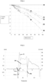
- Fig. 3 details the elements arranged downstream of the pressure sensor 55 of the gas delivery device 1, up to the patient P and Fig. 4 schematizes the pressure/flow rate relationship of these different elements, that is to say the resistance (i.e. a pressure) to the flow of a gas (i.e. a flow rate) passing through them.
- a patient P is first fluidically connected to the elements located downstream of the pressure sensor 55.
- the detection orifice 55a of the pressure sensor 55 is then at atmosphere, that is to say that the measured relative pressure is equal to 0 mbar.
- this gas flow rate Q will circulate in the internal gas passage 100, in particular at the level of the detection orifice 55a of the pressure sensor 55.
- the gas pressure existing in the breathing mask 10 is then the resultant of the pressure losses ( ⁇ P) of the different elements located downstream of the pressure sensor 55.
- This polynomial function is also represented in Fig. 4 in the form of solid curves.
- the control unit 50 in response to a flow rate measurement of 50 L/min by the flow rate determination means 60, can control the proportional valve 22 to minimize the pressure P M , that is to say pressurize the internal gas passage 100 so that at the detection orifice 55a of the pressure sensor 55, the pressure is positive, and in this specific case, equal to approximately 4 mbar.
- control unit 50 controls the solenoid valve 22 so that, in response to a flow rate request from the patient P, the pressure losses of the elements located downstream of the pressure sensor 55 are compensated.
- the pressure P M prevailing in the breathing mask 10 thus determined is therefore a “reconstituted pressure”.
- the patient P during therapy with administration of therapeutic gas, the patient P performs a succession of inspirations and expirations to inhale the therapeutic gas, for example an O2 /argon or N2O / O2 mixture, and exhale the CO2 -rich gases resulting from the pulmonary exchanges.
- the therapeutic gas for example an O2 /argon or N2O / O2 mixture
- control unit 50 is configured to ensure that at all times, the pressure prevailing in the mask 10 is as close as possible to atmospheric pressure (i.e. 1 atm), i.e. 0 mbar relative.
- control unit 50 controls the proportional valve 22 so that the flow rate provided by said proportional valve 22 is proportional to the reconstituted pressure P M in the mask 10.
- the control unit 50 therefore only acts on the proportional valve 22 if the pressure P M reconstituted in the mask 10 is negative, that is to say that the proportional valve 22 is controlled or remains in the closed position as soon as the pressure reconstituted in the mask 10 becomes positive.
- a proportionality then appears between the flow rate delivered by the proportional valve 22 and the negative pressure reconstituted in the mask 10. The more the pressure value deviates from 0 mbar, the higher the flow rate. Conversely, the closer the pressure value is to 0 mbar, the lower the flow rate.
- PID Proportional Integral, and Derivative
- the gas delivery apparatus 1 may comprise other elements, such as a human-machine interface (HMI) with an information display screen, preferably a touch screen, one or more selection keys or buttons, a start-up device, such as an on/off button, an alarm system and/or other elements.
- HMI human-machine interface
- Fig. 5 schematizes the operation of the control unit 50, in particular of the algorithm implemented by the microprocessor 51 of the gas delivery device 1, in response to an inspiration from the patient P.
- the inspiration of patient P is divided into two distinct successive portions I1 and I2 with I1 corresponding to the very beginning of the inspiration.
- I1 corresponding to the very beginning of the inspiration.
- the control unit 50 will control the proportional valve 22 to adjust the flow of therapeutic gas in order to limit the pressure drop in the mask 10.
- the pressure in the deformable reservoir 27 decreases, a sign that the latter is deflating and that a quantity of gas is circulating through the flow rate determination means 60 and the non-return valve 61 towards the mask 10, in order to meet the inspiratory demand of the patient P.
- This time t1 corresponds to the moment when the proportional solenoid valve 22 begins to open in response to the request from the control unit 50 and therefore to deliver a flow rate D, marking the transition to phase I2.
- the gas flow D will meet the needs of the patient P and at the same time fill the reservoir 27, the pressure P R of which will increase until it becomes zero again at t2, a sign that the reservoir 27 has returned to its resting state, i.e. fully filled.
- phase I2 after t2 sees tank 27 in an over-inflated situation because the pressure P R is positive, which is perfectly normal.
- control unit 50 controls the proportional valve 22 so that the pressure P M reconstituted in the mask 10 is as close as possible to 0, and in fact, compensates for the pressure losses of the elements located downstream of the pressure sensor 55, in response to a flow rate measured by the flow rate determination means 60.
- phase I2 gives way to an expiratory phase E1 where the patient exhales through the expiratory port 11.
- This exhalation then generates a positive reconstituted pressure P M in the mask 10 and the control unit 50 then controls the proportional valve 22 so as to interrupt the delivery of gas, i.e. the flow rate.
- the reservoir 27, itself under positive pressure P R empties progressively following the profile of the pressure P M prevailing in the mask 10.
- the reservoir 27 is essential for the proper functioning of the device 1. Indeed, if it were not present, the gas would circulate in rigid, i.e. non-deformable, elements, such as the internal gas passage 100 and the gas line 13. Thus, during phase I1, before the proportional valve 22 opens, the patient's respiratory demand would not be satisfied, thus causing major respiratory discomfort for the patient.
- the reservoir 27, throughout the inspiratory phase plays a buffer role by attenuating the effect of variations in the patient's ventilatory demand P and the response of the control unit 50 and the proportional valve 22, in response to these variations.
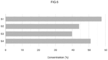
- Fig. 6 compares the performance of a gas delivery apparatus 1 according to the present invention and several prior art devices, such as a continuous flow system and a demand valve (VAD).
- VAD demand valve
- this comparison uses a test bench comprising an "electronic patient", namely a device mimicking the breathing of a patient, for example the ASL 5000 respiratory simulator available from Ingmar Medical, making it possible to repeatably simulate the breathing of a patient.
- an "electronic patient” namely a device mimicking the breathing of a patient, for example the ASL 5000 respiratory simulator available from Ingmar Medical, making it possible to repeatably simulate the breathing of a patient.
- the various devices tested are connected to the “electronic patient” by means of a gas delivery conduit with a calibrated orifice simulating a leak at the level of the respiratory mask.
- the therapeutic gas source provides a mixture of 60% argon and 40% oxygen (vol.%).
- the concentration of argon inhaled by the patient P is around 40% (vol.%) for the continuous flow system S3 and 45% for the demand valve S2, i.e. a loss of 20% and 15% in volume of argon respectively, which does not guarantee the effectiveness of the device when delivering gas to a patient since the argon content supplied to the patient is much lower than expected, i.e. 60% vol.
- the gas delivery device 1 (S1) of the invention makes it possible to significantly limit dilution with ambient air, by maintaining, under the same test conditions, a concentration of the order of 57 vol.%, i.e. approximately the desired content (i.e. 60%), thus fully guaranteeing therapeutic efficacy.
- the gas delivery device 1 without the means of limiting the depression in the mask (S4), remains superior to the existing devices (S2, S3) but nevertheless only ensures a concentration slightly higher than 50 vol.%, which is insufficient to guarantee the effectiveness of the argon treatment for which an effective content of 60 vol.% is desired.
- the gas delivery apparatus 1 therefore fully meets the needs of patient comfort and minimization of the impact of leakage in terms of reducing the concentration of inhaled gases, thus ensuring the desired therapeutic efficacy.
- This level of efficacy is only possible by associating, according to the invention, a deformable reservoir 27 and a control of the flow rate of gas delivered to the pressure reconstituted in the mask 10, as described above.
Landscapes
- Health & Medical Sciences (AREA)
- Pulmonology (AREA)
- Emergency Medicine (AREA)
- Life Sciences & Earth Sciences (AREA)
- Anesthesiology (AREA)
- Biomedical Technology (AREA)
- Heart & Thoracic Surgery (AREA)
- Hematology (AREA)
- Engineering & Computer Science (AREA)
- Animal Behavior & Ethology (AREA)
- General Health & Medical Sciences (AREA)
- Public Health (AREA)
- Veterinary Medicine (AREA)
- Critical Care (AREA)
- Respiratory Apparatuses And Protective Means (AREA)
- Measurement Of The Respiration, Hearing Ability, Form, And Blood Characteristics Of Living Organisms (AREA)
Claims (14)
- Gerät zur Abgabe von therapeutischem Gas (1), umfassend:- einen inneren Gasdurchgang (100), der in Fluidverbindung mit einem verformbaren Vorratsbehälter (27) steht, um dem verformbaren Vorratsbehälter (27) therapeutisches Gas zuzuführen und um aus dem verformbaren Vorratsbehälter (27) stammendes Gas zurückzugewinnen,- eine Ventilvorrichtung (22), die an dem inneren Gasdurchgang (100), stromauf des verformbaren Vorratsbehälters (27), angeordnet ist, um den Volumenstrom des dem verformbaren Vorratsbehälter (27) zugeführten therapeutischen Gases zu steuern,- eine Steuereinheit (50) mit Mikroprozessor (51), die die Ventilvorrichtung (22) ansteuert, um den die Ventilvorrichtung (22) durchquerenden Gasvolumenstrom festzulegen oder anzupassen,- Volumenstrombestimmungsmittel (60), die dazu eingerichtet sind, eine oder mehrere Druck- oder Volumenstrommessungen in dem inneren Gasdurchgang (100) vorzunehmen und die Messung(en) an die Steuereinheit (50) zu übertragen,- einen Drucksensor (55), der dazu ausgestaltet ist, eine oder mehrere Gasdruckmessungen (P55) des dem verformbaren Vorratsbehälter (27) zugeführten therapeutischen Gases vorzunehmen und die Gasdruckmessung (en) (P55) an die Steuereinheit (50) zu übermitteln, und- eine Beatmungsmaske (10), die in Fluidverbindung mit dem inneren Gasdurchgang (100) steht und der aus dem verformbaren Vorratsbehälter (27) stammendes therapeutisches Gas zugeführt wird, wobei- der Drucksensor (55) an dem inneren Gasdurchgang (100) zwischen der Ventilvorrichtung (22) und dem verformbaren Vorratsbehälter (27) angeordnet ist,- die Steuereinheit (50) dazu ausgestaltet ist:a) den Gasvolumenstrom (Q60), der in dem inneren Gasdurchgang (100) zirkuliert, anhand der Druck- oder Volumenstrommessung(en), die von den Volumenstrombestimmungsmitteln (60) übermittelt werden, zu bestimmen,b) den Gasdruck (P55) anhand der Gasdruckmessung(en) (P55) , die von dem Drucksensor (55) stammen, zu bestimmen,c) die Druckverluste (ΔP), die stromab des Drucksensors (55) vorliegen, anhand des Gasvolumenstroms (Q60) zu bestimmen,d) den Druck (PM) an der Beatmungsmaske (10) anhand des Gasdrucks (P55) und der Druckverluste (ΔP) zu bestimmen,e) und die Ventilvorrichtung (22) zu steuern, um den Gasvolumenstrom in Abhängigkeit von dem an der Beatmungsmaske (10) bestimmten Druck (PM) so anzupassen, dass der an der Beatmungsmaske (10) ausgeübte Druck auf einen Wert gleich dem atmosphärischen Druck angepasst wird.
- Gerät nach Anspruch 1, wobei die Steuereinheit (50) dazu ausgestaltet ist, die Druckverluste (ΔP) anhand einer gespeicherten Berechnungsformel zu bestimmen, so dass:
 - R eine Konstante ist, die für den "äquivalenten Widerstand" der Elemente steht, die zwischen dem Drucksensor 55 und der Beatmungsmaske 10 gelegen sind,- Q60 der Gasvolumenstrom (Q60) ist, der in dem inneren Gasdurchgang (100) zirkuliert.
 - Gerät nach einem der vorhergehenden Ansprüche, wobei die Volumenstrombestimmungsmittel (60) dazu eingerichtet sind, eine oder mehrere Druck- oder Volumenstrommessungen in dem inneren Gasdurchgang (100), stromab des verformbaren Vorratsbehälters (27), vorzunehmen.
- Gerät nach einem der vorhergehenden Ansprüche, wobei die Volumenstrombestimmungsmittel (60) einen Drucksensor oder einen Volumenstromsensor umfassen, insbesondere einen Differenzdrucksensor.
- Gerät nach Anspruch 2, wobei es Speichermittel umfasst, um die Berechnungsformel für die Druckverluste (ΔP) zu speichern.
- Gerät nach Anspruch 1, wobei die Ventilvorrichtung (22) ein Proportionalventil umfasst.
- Gerät nach Anspruch 1, wobei es ferner mindestens eine Rückflussverhinderungsvorrichtung (61) umfasst, die in dem inneren Gasdurchgang (100), stromab des verformbaren Vorratsbehälters (27), angeordnet ist.
- Gerät nach Anspruch 1, wobei die Beatmungsmaske (10) über eine flexible Gasleitung (13) in Fluidverbindung mit dem inneren Gasdurchgang (100) steht.
- Gerät nach Anspruch 1, wobei die Steuereinheit (50) mindestens eine Elektronikkarte umfasst, die mindestens einen Mikroprozessor trägt.
- Gerät nach Anspruch 8, wobei die Gasleitung (13) eine Filtereinrichtung (15) umfasst, insbesondere ein Wärme und Feuchtigkeit tauschendes Filter.
- Gerät nach Anspruch 1, wobei die Steuereinheit (50), mindestens ein Teil des inneren Gasdurchgangs (100), der verformbare Vorratsbehälter (27), die Volumenstrombestimmungsmittel (60) und die Ventilvorrichtung (22) in einem starren Außengehäuse (2) angeordnet sind.
- Gerät nach Anspruch 1, wobei die Beatmungsmaske eine Gesichtsmaske ist.
- Gerät nach Anspruch 1, wobei der Drucksensor (55):i) ein Relativdrucksensor ist, der eine Detektionsöffnung (55a) umfasst, die in dem inneren Gasdurchgang (100) angeordnet ist, und im Übrigen auf den atmosphärischen Druck bezogen ist (d. h. 0 mbar = 1 atm), undii) dazu ausgestaltet ist, eine oder mehrere Gasdruckmessungen (P55) zu übermitteln, die jeweils einer Differenz zwischen dem an der Detektionsöffnung (55a) bestimmten absoluten Druck und dem atmosphärischen Druck entsprechen.
- Gerät nach Anspruch 1, wobei eine Quelle für therapeutisches Gas (3) fluidisch an den inneren Gasdurchgang (100) angeschlossen ist, um dem Gasdurchgang (100) therapeutisches Gas zuzuführen, wobei die Quelle (3) für therapeutisches Gas einen oder mehrere Gasbehälter (30) umfasst, umfassend:- einen Gasbehälter (30), der ein O2/N2O-Gasgemisch oder ein O2/Argon-Gasgemisch enthält, oder- einen ersten Gasbehälter (30), der Argon oder N2O enthält, einen zweiten Gasbehälter (30), der Sauerstoff (O2) enthält, und einen Gasmischer, dem Gas von den ersten und zweiten Gasbehältern (30) zugeführt wird, um ein Mischen der aus den ersten und zweiten Gasbehältern (30) stammenden Gase vorzunehmen und ein O2/N2O- oder Q2/Argon-Gasgemisch zu erhalten.
Applications Claiming Priority (1)
| Application Number | Priority Date | Filing Date | Title |
|---|---|---|---|
| FR2101085A FR3119330B1 (fr) | 2021-02-04 | 2021-02-04 | Appareil de fourniture de gaz thérapeutique à un patient avec contrôle de la pression au masque |
Publications (2)
| Publication Number | Publication Date |
|---|---|
| EP4039302A1 EP4039302A1 (de) | 2022-08-10 |
| EP4039302B1 true EP4039302B1 (de) | 2024-10-09 |
Family
ID=75850283
Family Applications (1)
| Application Number | Title | Priority Date | Filing Date |
|---|---|---|---|
| EP22150582.9A Active EP4039302B1 (de) | 2021-02-04 | 2022-01-07 | Gerät zur therapeutischen gasversorgung eines patienten mit steuerung des maskendrucks |
Country Status (4)
| Country | Link |
|---|---|
| US (1) | US12318547B2 (de) |
| EP (1) | EP4039302B1 (de) |
| ES (1) | ES3004685T3 (de) |
| FR (1) | FR3119330B1 (de) |
Families Citing this family (2)
| Publication number | Priority date | Publication date | Assignee | Title |
|---|---|---|---|---|
| FR3114752B1 (fr) * | 2020-10-06 | 2022-09-16 | Lair Liquide Sa Pour L’Etude Et Lexploitation Des Procedes Georges Claude | Appareil et installation de fourniture de gaz thérapeutique à un patient avec contrôle du débit |
| US20230166063A1 (en) * | 2021-11-29 | 2023-06-01 | Kuwait University | Ventilator and inflation bag operation of ventilator |
Family Cites Families (6)
| Publication number | Priority date | Publication date | Assignee | Title |
|---|---|---|---|---|
| US7438073B2 (en) * | 2002-03-08 | 2008-10-21 | Kaerys S.A. | Air assistance apparatus for computing the airflow provided by only means of pressure sensors |
| US7044129B1 (en) * | 2003-09-03 | 2006-05-16 | Ric Investments, Llc. | Pressure support system and method |
| WO2011089491A1 (en) * | 2010-01-22 | 2011-07-28 | Koninklijke Philips Electronics N.V. | Automatically controlled ventilation system |
| EP3319672A1 (de) * | 2015-07-07 | 2018-05-16 | Koninklijke Philips N.V. | Verfahren und systeme zur patientenatemwegs- und leckströmungsschätzung für nichtinvasive beatmung |
| WO2019213591A1 (en) * | 2018-05-03 | 2019-11-07 | Umbulizer LLC | Ventilation apparatus |
| EP3698833A1 (de) * | 2019-02-21 | 2020-08-26 | L'air Liquide, Societe Anonyme Pour L'etude Et L'exploitation Des Procedes Georges Claude | Automatische gaszufuhrvorrichtung |
-
2021
- 2021-02-04 FR FR2101085A patent/FR3119330B1/fr active Active
-
2022
- 2022-01-07 ES ES22150582T patent/ES3004685T3/es active Active
- 2022-01-07 EP EP22150582.9A patent/EP4039302B1/de active Active
- 2022-02-04 US US17/592,927 patent/US12318547B2/en active Active
Also Published As
| Publication number | Publication date |
|---|---|
| EP4039302A1 (de) | 2022-08-10 |
| US12318547B2 (en) | 2025-06-03 |
| ES3004685T3 (en) | 2025-03-12 |
| FR3119330B1 (fr) | 2023-05-05 |
| US20220241545A1 (en) | 2022-08-04 |
| FR3119330A1 (fr) | 2022-08-05 |
Similar Documents
| Publication | Publication Date | Title |
|---|---|---|
| EP3906955B1 (de) | Vorrichtung zur zuführung von therapeutischem gas, insbesondere no, zu einem patienten | |
| EP0344280B1 (de) | Arbeitsverfahren einer Beatmungsvorrichtung und eine solche Vorrichtung | |
| EP4026577B1 (de) | Anlage zur versorgung eines patienten mit therapeutischem gas unter berücksichtigung von undichtigkeiten an der maske | |
| EP4039302B1 (de) | Gerät zur therapeutischen gasversorgung eines patienten mit steuerung des maskendrucks | |
| EP4209243A1 (de) | No-ausgabevorrichtung mit notfalldosiersystem | |
| EP4295882A1 (de) | Anzeige der no-dosis durch eine vorrichtung zur bereitstellung von no in pausenphase | |
| EP3981454B1 (de) | Gerät und anlage zur therapeutischen gasversorgung eines patienten mit durchsatzsteuerung | |
| FR3031313A1 (fr) | Appareil d'assistance respiratoire avec detection de tout arret de la turbine | |
| FR2908975A1 (fr) | Procede d'acquisition du volume de gaz d'expiration reaspire dans un systeme de respiration assistee | |
| EP4483931B1 (de) | Anzeige eines wartungserinnerungsrückrufs auf einem medizinischen stickoxidbereitstellungsgerät | |
| WO2018037166A1 (fr) | Dispositif médical d'administration en circuit fermé d'un mélange gazeux à un patient respirant spontanément et système de réglage associé | |
| EP4052748B1 (de) | Schnittstelle für die patientenbeatmung zur kopplung an ein medizinisches beatmungsgerät und eine gasquelle | |
| WO2019206963A1 (fr) | Appareil respiratoire de plongée sous-marine à recyclage de gaz en circuit semi-fermé | |
| EP4427780B1 (de) | Atemgasversorgungsanlage mit geschlossenem kreislauf | |
| EP4678212A1 (de) | Installation zur bereitstellung von no, bestehend aus einem no-abgabegerät und einem anästhesiebeatmungsgerät | |
| EP4458394A1 (de) | Vorrichtung zur abgabe von gasförmigem stickstoffmonoxid im proportional- oder pulsbetrieb | |
| FR3162006A1 (fr) | Appareil de fourniture de NO adapté au transport terrestre ou aérien | |
| FR3066120A1 (fr) | Appareil d'assistance respiratoire avec estimation de la fraction d'oxygene inspiree | |
| EP4640257A1 (de) | Anlage zur bereitstellung von no mit einer von gasflaschen gespeisten no-abgabevorrichtung | |
| CA3247526A1 (fr) | Affichage d’une dose de no de depart prefixee sur un appareil de fourniture de gaz medical | |
| FR3151765A1 (fr) | Installation d’administration de NO gazeux comprenant un ventilateur médical à humidificateur intégré | |
| FR3031447A1 (fr) | Ventilateur medical a vanne d'echappement proportionnelle associee a un capteur de debit bidirectionnel |
Legal Events
| Date | Code | Title | Description |
|---|---|---|---|
| PUAI | Public reference made under article 153(3) epc to a published international application that has entered the european phase |
Free format text: ORIGINAL CODE: 0009012 |
|
| STAA | Information on the status of an ep patent application or granted ep patent |
Free format text: STATUS: THE APPLICATION HAS BEEN PUBLISHED |
|
| AK | Designated contracting states |
Kind code of ref document: A1 Designated state(s): AL AT BE BG CH CY CZ DE DK EE ES FI FR GB GR HR HU IE IS IT LI LT LU LV MC MK MT NL NO PL PT RO RS SE SI SK SM TR |
|
| STAA | Information on the status of an ep patent application or granted ep patent |
Free format text: STATUS: REQUEST FOR EXAMINATION WAS MADE |
|
| 17P | Request for examination filed |
Effective date: 20230210 |
|
| RBV | Designated contracting states (corrected) |
Designated state(s): AL AT BE BG CH CY CZ DE DK EE ES FI FR GB GR HR HU IE IS IT LI LT LU LV MC MK MT NL NO PL PT RO RS SE SI SK SM TR |
|
| GRAP | Despatch of communication of intention to grant a patent |
Free format text: ORIGINAL CODE: EPIDOSNIGR1 |
|
| STAA | Information on the status of an ep patent application or granted ep patent |
Free format text: STATUS: GRANT OF PATENT IS INTENDED |
|
| INTG | Intention to grant announced |
Effective date: 20240515 |
|
| GRAS | Grant fee paid |
Free format text: ORIGINAL CODE: EPIDOSNIGR3 |
|
| GRAA | (expected) grant |
Free format text: ORIGINAL CODE: 0009210 |
|
| STAA | Information on the status of an ep patent application or granted ep patent |
Free format text: STATUS: THE PATENT HAS BEEN GRANTED |
|
| AK | Designated contracting states |
Kind code of ref document: B1 Designated state(s): AL AT BE BG CH CY CZ DE DK EE ES FI FR GB GR HR HU IE IS IT LI LT LU LV MC MK MT NL NO PL PT RO RS SE SI SK SM TR |
|
| REG | Reference to a national code |
Ref country code: CH Ref legal event code: EP |
|
| REG | Reference to a national code |
Ref country code: DE Ref legal event code: R096 Ref document number: 602022006551 Country of ref document: DE |
|
| REG | Reference to a national code |
Ref country code: IE Ref legal event code: FG4D Free format text: LANGUAGE OF EP DOCUMENT: FRENCH |
|
| REG | Reference to a national code |
Ref country code: LT Ref legal event code: MG9D |
|
| REG | Reference to a national code |
Ref country code: NL Ref legal event code: MP Effective date: 20241009 |
|
| REG | Reference to a national code |
Ref country code: ES Ref legal event code: FG2A Ref document number: 3004685 Country of ref document: ES Kind code of ref document: T3 Effective date: 20250312 |
|
| REG | Reference to a national code |
Ref country code: AT Ref legal event code: MK05 Ref document number: 1729913 Country of ref document: AT Kind code of ref document: T Effective date: 20241009 |
|
| PG25 | Lapsed in a contracting state [announced via postgrant information from national office to epo] |
Ref country code: NL Free format text: LAPSE BECAUSE OF FAILURE TO SUBMIT A TRANSLATION OF THE DESCRIPTION OR TO PAY THE FEE WITHIN THE PRESCRIBED TIME-LIMIT Effective date: 20241009 |
|
| PG25 | Lapsed in a contracting state [announced via postgrant information from national office to epo] |
Ref country code: NL Free format text: LAPSE BECAUSE OF FAILURE TO SUBMIT A TRANSLATION OF THE DESCRIPTION OR TO PAY THE FEE WITHIN THE PRESCRIBED TIME-LIMIT Effective date: 20241009 |
|
| PG25 | Lapsed in a contracting state [announced via postgrant information from national office to epo] |
Ref country code: PT Free format text: LAPSE BECAUSE OF FAILURE TO SUBMIT A TRANSLATION OF THE DESCRIPTION OR TO PAY THE FEE WITHIN THE PRESCRIBED TIME-LIMIT Effective date: 20250210 Ref country code: HR Free format text: LAPSE BECAUSE OF FAILURE TO SUBMIT A TRANSLATION OF THE DESCRIPTION OR TO PAY THE FEE WITHIN THE PRESCRIBED TIME-LIMIT Effective date: 20241009 Ref country code: IS Free format text: LAPSE BECAUSE OF FAILURE TO SUBMIT A TRANSLATION OF THE DESCRIPTION OR TO PAY THE FEE WITHIN THE PRESCRIBED TIME-LIMIT Effective date: 20250209 |
|
| PGFP | Annual fee paid to national office [announced via postgrant information from national office to epo] |
Ref country code: DE Payment date: 20250121 Year of fee payment: 4 |
|
| PG25 | Lapsed in a contracting state [announced via postgrant information from national office to epo] |
Ref country code: FI Free format text: LAPSE BECAUSE OF FAILURE TO SUBMIT A TRANSLATION OF THE DESCRIPTION OR TO PAY THE FEE WITHIN THE PRESCRIBED TIME-LIMIT Effective date: 20241009 |
|
| PG25 | Lapsed in a contracting state [announced via postgrant information from national office to epo] |
Ref country code: BG Free format text: LAPSE BECAUSE OF FAILURE TO SUBMIT A TRANSLATION OF THE DESCRIPTION OR TO PAY THE FEE WITHIN THE PRESCRIBED TIME-LIMIT Effective date: 20241009 |
|
| PGFP | Annual fee paid to national office [announced via postgrant information from national office to epo] |
Ref country code: ES Payment date: 20250226 Year of fee payment: 4 |
|
| PG25 | Lapsed in a contracting state [announced via postgrant information from national office to epo] |
Ref country code: NO Free format text: LAPSE BECAUSE OF FAILURE TO SUBMIT A TRANSLATION OF THE DESCRIPTION OR TO PAY THE FEE WITHIN THE PRESCRIBED TIME-LIMIT Effective date: 20250109 |
|
| PG25 | Lapsed in a contracting state [announced via postgrant information from national office to epo] |
Ref country code: LV Free format text: LAPSE BECAUSE OF FAILURE TO SUBMIT A TRANSLATION OF THE DESCRIPTION OR TO PAY THE FEE WITHIN THE PRESCRIBED TIME-LIMIT Effective date: 20241009 Ref country code: AT Free format text: LAPSE BECAUSE OF FAILURE TO SUBMIT A TRANSLATION OF THE DESCRIPTION OR TO PAY THE FEE WITHIN THE PRESCRIBED TIME-LIMIT Effective date: 20241009 Ref country code: GR Free format text: LAPSE BECAUSE OF FAILURE TO SUBMIT A TRANSLATION OF THE DESCRIPTION OR TO PAY THE FEE WITHIN THE PRESCRIBED TIME-LIMIT Effective date: 20250110 |
|
| PG25 | Lapsed in a contracting state [announced via postgrant information from national office to epo] |
Ref country code: PL Free format text: LAPSE BECAUSE OF FAILURE TO SUBMIT A TRANSLATION OF THE DESCRIPTION OR TO PAY THE FEE WITHIN THE PRESCRIBED TIME-LIMIT Effective date: 20241009 |
|
| PGFP | Annual fee paid to national office [announced via postgrant information from national office to epo] |
Ref country code: FR Payment date: 20250128 Year of fee payment: 4 |
|
| PGFP | Annual fee paid to national office [announced via postgrant information from national office to epo] |
Ref country code: IT Payment date: 20250131 Year of fee payment: 4 |
|
| PG25 | Lapsed in a contracting state [announced via postgrant information from national office to epo] |
Ref country code: RS Free format text: LAPSE BECAUSE OF FAILURE TO SUBMIT A TRANSLATION OF THE DESCRIPTION OR TO PAY THE FEE WITHIN THE PRESCRIBED TIME-LIMIT Effective date: 20250109 |
|
| PG25 | Lapsed in a contracting state [announced via postgrant information from national office to epo] |
Ref country code: SM Free format text: LAPSE BECAUSE OF FAILURE TO SUBMIT A TRANSLATION OF THE DESCRIPTION OR TO PAY THE FEE WITHIN THE PRESCRIBED TIME-LIMIT Effective date: 20241009 |
|
| PG25 | Lapsed in a contracting state [announced via postgrant information from national office to epo] |
Ref country code: DK Free format text: LAPSE BECAUSE OF FAILURE TO SUBMIT A TRANSLATION OF THE DESCRIPTION OR TO PAY THE FEE WITHIN THE PRESCRIBED TIME-LIMIT Effective date: 20241009 |
|
| REG | Reference to a national code |
Ref country code: DE Ref legal event code: R097 Ref document number: 602022006551 Country of ref document: DE |
|
| PG25 | Lapsed in a contracting state [announced via postgrant information from national office to epo] |
Ref country code: EE Free format text: LAPSE BECAUSE OF FAILURE TO SUBMIT A TRANSLATION OF THE DESCRIPTION OR TO PAY THE FEE WITHIN THE PRESCRIBED TIME-LIMIT Effective date: 20241009 |
|
| PG25 | Lapsed in a contracting state [announced via postgrant information from national office to epo] |
Ref country code: RO Free format text: LAPSE BECAUSE OF FAILURE TO SUBMIT A TRANSLATION OF THE DESCRIPTION OR TO PAY THE FEE WITHIN THE PRESCRIBED TIME-LIMIT Effective date: 20241009 |
|
| PG25 | Lapsed in a contracting state [announced via postgrant information from national office to epo] |
Ref country code: SK Free format text: LAPSE BECAUSE OF FAILURE TO SUBMIT A TRANSLATION OF THE DESCRIPTION OR TO PAY THE FEE WITHIN THE PRESCRIBED TIME-LIMIT Effective date: 20241009 |
|
| PG25 | Lapsed in a contracting state [announced via postgrant information from national office to epo] |
Ref country code: CZ Free format text: LAPSE BECAUSE OF FAILURE TO SUBMIT A TRANSLATION OF THE DESCRIPTION OR TO PAY THE FEE WITHIN THE PRESCRIBED TIME-LIMIT Effective date: 20241009 |
|
| PLBE | No opposition filed within time limit |
Free format text: ORIGINAL CODE: 0009261 |
|
| STAA | Information on the status of an ep patent application or granted ep patent |
Free format text: STATUS: NO OPPOSITION FILED WITHIN TIME LIMIT |
|
| REG | Reference to a national code |
Ref country code: CH Ref legal event code: PL |
|
| PG25 | Lapsed in a contracting state [announced via postgrant information from national office to epo] |
Ref country code: SE Free format text: LAPSE BECAUSE OF FAILURE TO SUBMIT A TRANSLATION OF THE DESCRIPTION OR TO PAY THE FEE WITHIN THE PRESCRIBED TIME-LIMIT Effective date: 20241009 |
|
| PG25 | Lapsed in a contracting state [announced via postgrant information from national office to epo] |
Ref country code: MC Free format text: LAPSE BECAUSE OF FAILURE TO SUBMIT A TRANSLATION OF THE DESCRIPTION OR TO PAY THE FEE WITHIN THE PRESCRIBED TIME-LIMIT Effective date: 20241009 Ref country code: LU Free format text: LAPSE BECAUSE OF NON-PAYMENT OF DUE FEES Effective date: 20250107 |
|
| 26N | No opposition filed |
Effective date: 20250710 |
|
| PG25 | Lapsed in a contracting state [announced via postgrant information from national office to epo] |
Ref country code: BE Free format text: LAPSE BECAUSE OF NON-PAYMENT OF DUE FEES Effective date: 20250131 |
|
| PG25 | Lapsed in a contracting state [announced via postgrant information from national office to epo] |
Ref country code: CH Free format text: LAPSE BECAUSE OF NON-PAYMENT OF DUE FEES Effective date: 20250131 |
|
| REG | Reference to a national code |
Ref country code: BE Ref legal event code: MM Effective date: 20250131 |
|
| PG25 | Lapsed in a contracting state [announced via postgrant information from national office to epo] |
Ref country code: IE Free format text: LAPSE BECAUSE OF NON-PAYMENT OF DUE FEES Effective date: 20250107 |