EP4039117A1 - Helmet - Google Patents
Helmet Download PDFInfo
- Publication number
- EP4039117A1 EP4039117A1 EP22155299.5A EP22155299A EP4039117A1 EP 4039117 A1 EP4039117 A1 EP 4039117A1 EP 22155299 A EP22155299 A EP 22155299A EP 4039117 A1 EP4039117 A1 EP 4039117A1
- Authority
- EP
- European Patent Office
- Prior art keywords
- helmet
- protective shell
- head
- head pad
- protrusions
- Prior art date
- Legal status (The legal status is an assumption and is not a legal conclusion. Google has not performed a legal analysis and makes no representation as to the accuracy of the status listed.)
- Withdrawn
Links
Images



Classifications
-
- A—HUMAN NECESSITIES
- A42—HEADWEAR
- A42B—HATS; HEAD COVERINGS
- A42B3/00—Helmets; Helmet covers ; Other protective head coverings
- A42B3/04—Parts, details or accessories of helmets
- A42B3/10—Linings
- A42B3/12—Cushioning devices
-
- A—HUMAN NECESSITIES
- A42—HEADWEAR
- A42B—HATS; HEAD COVERINGS
- A42B3/00—Helmets; Helmet covers ; Other protective head coverings
- A42B3/04—Parts, details or accessories of helmets
- A42B3/10—Linings
- A42B3/14—Suspension devices
-
- A—HUMAN NECESSITIES
- A42—HEADWEAR
- A42B—HATS; HEAD COVERINGS
- A42B3/00—Helmets; Helmet covers ; Other protective head coverings
- A42B3/04—Parts, details or accessories of helmets
- A42B3/18—Face protection devices
- A42B3/22—Visors
- A42B3/225—Visors with full face protection, e.g. for industrial safety applications
-
- A—HUMAN NECESSITIES
- A42—HEADWEAR
- A42B—HATS; HEAD COVERINGS
- A42B3/00—Helmets; Helmet covers ; Other protective head coverings
- A42B3/04—Parts, details or accessories of helmets
- A42B3/28—Ventilating arrangements
- A42B3/286—Ventilating arrangements with forced flow, e.g. by a fan
Definitions
- the present disclosure relates to a helmet, particularly, but not exclusively, a safety helmet.
- Other aspects of the present disclosure relate to a PAPR kit including the helmet.
- the helmet's shell is a rigid outer section and may be made from a variety of different materials, such as polyethylene, ABS (Acrylonitrile Butadiene Styrene), or fibreglass hardened with polyester resins.
- the type of helmet and materials used for the shell will depend on the nature of the work performed and the expected injury hazards associated.
- a harness is the internal part of the safety helmet (typically fastened to the inside of the shell) consisting of one or more straps made of woven bands or polyethylene.
- the main purpose of the harness is to absorb energy from an impact on the shell and to spread the force evenly over the wearer's head, minimising the risk of harm to the user.
- helmets are used in the military field. Such military helmet include a shell that is typically made of carbon or steel and intended to protect the user from projectiles or other forms of impact. Military grade helmets may include a harness as explained above or a foam interior to soften harmful impacts.
- Helmets can also feature other, optional equipment, such as a chinstrap, which is designed to keep the helmet in place and prevents it from falling when users move their heads, or other protective elements, such as face or ear protection.
- visors or optical devices e.g. night vision goggles
- visors or optical devices are attached to a front end of the helmet, with the weight of the visor causing an imbalance. This imbalance is detrimental to optimal positioning of the helmet on a user's head, which may compromise the protection conferred by the helmet. This is because helmets are constructed to be worn in a certain position to achieve best protection. Movement of the helmet due to imbalances caused by the visor or optical devices, therefore, need to be avoided.
- a helmet comprising a protective shell, a face shield and/or optical device connected to the protective shell; and a head pad arranged inside the protective shell such that the pad is substantially centred on a user's head, when in use, said head pad comprising a first surface facing away from the protective shell and adapted to contact a user's head, when in use, the first surface comprising a plurality of protrusions, wherein the protrusions are made of an elastic material.
- the head pad is made of an elastic material.
- the entire head pad is made of elastic material.
- the head pad may be made from a single, elastic material.
- the head pad is made of a polymeric material, particularly rubber or silicone, that provides a friction fit between the head pad and a user's head, when in use
- the protrusions may be substantially cylindrical in shape.
- the protrusions may have a diameter below 10mm.
- the protrusions may have a height below 10mm.
- Adjacent protrusions may be spaced by a gap of up to 10mm.
- the head pad may have a thickness of 0 to 10mm.
- the head pad has a substantially circular, oval, square, or rectangular shape.
- the head pad comprises a second surface facing an inner surface of the protective shell, said second surface being spaced from the inner surface of the protective shell.
- the head pad is suspended by a harness arranged inside the protective shell and configured to secure the protective shell to a user's head, when in use.
- the harness further includes a plurality of straps connecting the head pad to the protective shell.
- the head pad comprises a plurality of openings, and wherein each of the plurality of straps extends through at least one of the openings.
- the head pad may not be connected to the helmet via a harness. Rather, the head pad may be attached directly (e.g. by means of an adhesive) to an inner surface of the protective shell. This may be particularly useful for military grade helmets that do not always include a harness.
- the harness further comprises a headband connected to the plurality of straps.
- the face shield may be a visor for welding.
- the face shield may also be a simple transparent plastic shield, e.g. for disease control.
- the face shield is pivotably attached to the protective shell and transferrable between an active and an inactive position.
- the helmet comprises an airduct having an outlet at a front end of the protective shell and an inlet at rear end of the protective shell, the inlet being adapted for removably connecting an air supply hose.
- the helmet is a safety helmet or a military helmet.
- a PAPR kit comprising a helmet according to one of the embodiments above, an air blower unit for generation of forced air flow, and an air supply hose for supply of forced air flow from the air blower unit to the helmet.
- FIGS 1A and 1B show side views of a helmet, particularly a safety helmet, according to an embodiment of the present invention.
- the helmet 100 comprises a protective shell 102.
- the protective shell may have a semi-spherical shape, as is typically the case for protective shells of helmets.
- the helmet 100 further comprises a face shield 104.
- the face shield 104 may be a welding mask including various elements that will protect the user from injury during welding operations.
- the present disclosure is not limited to the use of a helmet with a faceshield or visor. Rather, the helmet may additionally or alternatively include any other equipment (e.g. optical equipment such as night vision goggles) that is connected to the front end of the protective shell.
- the face shield 104 is pivotably connected to the protective shell 102 by means of pivots (only left pivot shown in Figures 1A and 1B ) 106.
- the face shield is a two-part structure with a visor 108 that is pivotably connected to a face cover 110 of the face shield 104.
- the face shield 104 of this embodiment is connected to the first pivot 106 via the face cover 110.
- the visor 108 is connected to the face cover 110 via a second pivot 112.
- the visor 108 may be pivoted with respect to the face cover 110 in order to remove the eye protection to allow the user a clearer view of the working environment. It will be appreciated that Figures 1A and 1B show the visor 108 in its active position, i.e. when the visor 108 is aligned with the face cover 110.
- the face shield 104 may be fixed to the face cover and only be able to be pivoted with respect to the protective shell, together with the face cover.
- the invention is also not necessarily limited to welding mask-type face shields. Rather any face shield that may be attached to a front end of the protective shell 102 will benefit from the technical effects of the present disclosure.
- a face shield may simply be a pivotable plastic/glass screen.
- the face shield may also be fixed, i.e. non-pivotable, with respect to the protective shell.
- the helmet 100 shown in Figures 1A and 1B comprises a headband 114.
- the headband 114 is connected to an inner surface of the protective shell 102.
- the headband 114 is configured to contour the head of the user at a height of the forehead and the base of the skull. Together with a harness (described below), the headband 114 allows for stable positioning of the helmet on the user's head.
- the headband 114 comprises an adjustment mechanism 116.
- the adjustment mechanism 116 is configured to allow a user to change the length of the headband 114 to fit the circumference of their head.
- the adjustment mechanism 116 may be a ratchet mechanism that can be turned in a first direction in order to tighten the headband, and in an opposite, second direction to loosen the headband.
- the helmet 100 shown in Figures 1A and 1B is suitable for use with a powered air purifying respirator (PAPR).
- the helmet 100 comprises an air inlet 118.
- the air inlet 118 is arranged at a rear end of the protective shell 102.
- the air inlet 118 is configured to be connected with an air supply hose 120.
- the air supply hose 120 may deliver forced air from an air blower unit of a PAPR kit. Air flow entering the air inlet 118 via the air supply hose 120 may be directed from the rear end of the protective shell 102 towards a front end, i.e. close to the face shield 104, as will be described with more detail with respect to Figure 2 below.
- FIGS 1A and 1B only show a specific embodiment of the helmet according to the present disclosure, which is suitable for welding purposes.
- the helmet of the present disclosure may not only be useful in welding applications and some embodiments of the helmet may not include an air inlet at all and, thus, may not be suitable for connection to a PAPR kit.
- Figure 1A shows the helmet 100 with the face shield 104 in its inactive position.
- the face shield 104 is pivoted with respect to the protective shell 102 (e.g. pivoted upwards), such that the user's face is no longer covered by the face shield.
- this inactive position of the face shield may be useful during breaks from welding works, e.g. when the user is in a conversation with a co-worker.
- FIG 1B shows the helmet 100 of Figure 1A with the face shield 104 in its active position.
- the face shield 104 In its active position, the face shield 104 is arranged to cover the user's face (e.g. flipped down). Particularly in this active (flipped down) position shown in Figure 1B , and more specifically during the process of flipping down the face shield 104, the weight of the face shield 104 may cause the protective shell 102 of the helmet 100 to shift on the user's head. In particular, the helmet 100 may "slide" into the user's face. Similarly, as the face shield is transferred from the active position shown in Figure 1B into the inactive position shown in Figure 1A , the helmet 100 may shift backwards.
- the protective shell 102 comprises an outer wall 101 and an inner wall 103.
- the outer wall 101 is connected to the inner wall 103 by a plurality of reinforcement structures 105.
- the protective shell 102 comprises a double-walled structure.
- the double-walled structure may be used to receive the headband in a space between the inner and outer walls 101, 103 of the protective shell 102.
- the headband 114 may comprise a plurality of tabs 134, each of which is received within a guide of the double-walled structure of the protective shell 102.
- the face shield 104 is connected to the front of the protective shell 102 via the pivot 106.
- the pivot 106 extends between the outer wall 101 of the protective shell 102 and an inner surface of face shield 104.
- the face shield 104 comprises a face cover 110.
- the face cover 110 is configured to cover a user's chin, neck and mouth.
- the face shield 104 is a welding mask. Accordingly, the face cover 110 is made of a heat resistant material that can protect the user's face from sparks created during the welding process.
- a visor 108 is pivotally attached to the face cover 110 as described above.
- the visor 108 may include an auto-darkening filter.
- the filter When the user is not welding, the filter may be a relatively transparent, allowing good vision for job set up and torch positioning. As soon as an arc is struck, the visor 108 may darken to a welding shade, thereby protecting the user's eyes form UV damage during the welding process.
- the welding shade of the visor 108 may be adjustable, lighter or darker. When the user interrupts the welding process, the visor 108 may automatically return to a its initial, relatively transparent condition.
- a head pad 130 is suspended within the protective shell 102 of the helmet 100.
- the head pad 130 is received within a concave portion of the protective shell 102 and is distanced from an inner surface of the inner wall 103 of the protective shell 102.
- the head pad 130 is suspended within the protective shell 102 by means of straps 122, 124, 126.
- the straps are connected at their ends to the headband 114. Between their ends, the straps are threaded through slots of the pad 130, so as to hold the pad 130 centrally within the protective shell 102.
- the length of the straps 122, 124, 126 is selected such that the head pad 130 does not contact the inner surface of the inner wall 103, when being suspended by the straps 122, 124, 126.
- the head pad 130 is made of a high-friction material.
- the material of the head pad is constructed to provide a secure friction fit between the pad and the user's head, such that the helmet is prevented from shifting to the front or rear of the user's head.
- the head pad is made of a polymeric material, such as rubber or silicone.
- the head pad 130 shown in Figure 2 comprises a plurality of protrusions 132.
- the protrusions 132 extend over a first surface 136 of the head pad.
- the first surface 136 faces away from the protective shell 102 and is adapted to contact the user's head, when in use.
- it is the protrusions 132 that will contact the user's head, when in use.
- the head pad 130 is a single piece, i.e. the first surface 136 and the protrusions 132 are a unitary part and made from the same material.
- the protrusions 132 may also be made from rubber or silicone providing the protrusions 132 with elasticity.
- the elastic protrusions 132 will increase the friction between the user's head and the head pad. Accordingly, the protrusions will further prevent the helmet 100 from slipping across the user's head.
- the protrusions 132 may similarly be made from a different material to the head pad. However, the protrusions 132 should always be made from a material that provides some elasticity to counteract any potential movement of the helmet 100 with respect to the user's head.
- Figure 2 further shows an airduct 140 that is arranged along the inner surface of the inner wall 103.
- the airduct 140 extends between the air inlet 118 ( Figures 1A and 1B ) and an air outlet 142.
- the air outlet 142 is arranged at a front end of the protective shell 102. Accordingly, the air outlet is arranged such that forced air flowing into the airduct 140 via the air inlet 118 is directed towards the face shield 104, thereby supplying the user with a constant flow of fresh air.
- an airduct 140 is an optional feature that may only be required if the helmet is used as part of a PAPR kit.
- FIG. 3A and 3B there is shown another embodiment of a head pad 200.
- the head pad 200 may be installed within a helmet, such as the helmet shown in Figures 1A , 1B , and 2 , e.g. by means of one or more straps.
- the head pad 200 comprises six openings 204, 206, 208, 210, 212, and 214.
- Each strap of a corresponding helmet may extend through two opposite openings.
- one strap may extend through a first opening 204 and a fourth opening 210
- a second strap may extend through a second opening 206 and a fifth opening 212
- a third strap may extend through a third opening 208 and a sixth opening 214.
- the openings 204 to 214 may be used to suspend the pad within the protective shell of a corresponding helmet by means of a plurality of straps.
- the pad 200 comprises a first surface 202.
- the head pad 200 is arranged to be installed inside the cavity of a helmet in such a way that the first surface 202 faces away from the protective shell.
- a plurality of protrusions 216 are arranged on and protrude over the first surface 202.
- Figure 3B shows an enlarged view of the protrusions of the pad 200 shown in Figure 3A .
- the centres of adjacent protrusion 216A, 216B may be distanced from each other by a distance 218 by up to 10mm.
- adjacent protrusions 216A, 216B may be separated from each other by a gap of up to 10mm.
- the protrusions 216 of the embodiment shown in Figures 3A and 3B have a cylindrical shape. However, any other shape may be feasible that allows the protrusions to extend over the first surface 202.
- the cylindrical protrusions 216 shown in Figures 3A and 3B may have a diameter 220 below 10mm.
- the protrusions may further have a height of up to 10mm. The height of the protrusions refers to the distance between the first surface and the tip of the protrusions.
Landscapes
- Respiratory Apparatuses And Protective Means (AREA)
- Helmets And Other Head Coverings (AREA)
Abstract
Description
- The present disclosure relates to a helmet, particularly, but not exclusively, a safety helmet. Other aspects of the present disclosure relate to a PAPR kit including the helmet.
- Safety helmets have been of vital importance in the construction industry for decades. This type of helmet is predominantly used to protect the wearer from head injuries due to falling objects, impact with other objects, debris, etc. The helmet's shell is a rigid outer section and may be made from a variety of different materials, such as polyethylene, ABS (Acrylonitrile Butadiene Styrene), or fibreglass hardened with polyester resins. The type of helmet and materials used for the shell will depend on the nature of the work performed and the expected injury hazards associated.
- A harness is the internal part of the safety helmet (typically fastened to the inside of the shell) consisting of one or more straps made of woven bands or polyethylene. The main purpose of the harness is to absorb energy from an impact on the shell and to spread the force evenly over the wearer's head, minimising the risk of harm to the user.
- Other known helmets are used in the military field. Such military helmet include a shell that is typically made of carbon or steel and intended to protect the user from projectiles or other forms of impact. Military grade helmets may include a harness as explained above or a foam interior to soften harmful impacts.
- Helmets can also feature other, optional equipment, such as a chinstrap, which is designed to keep the helmet in place and prevents it from falling when users move their heads, or other protective elements, such as face or ear protection. There is a particularly increasing demand for visors or optical devices (e.g. night vision goggles) that can be attached to the helmet. Typically, visors or optical devices are attached to a front end of the helmet, with the weight of the visor causing an imbalance. This imbalance is detrimental to optimal positioning of the helmet on a user's head, which may compromise the protection conferred by the helmet. This is because helmets are constructed to be worn in a certain position to achieve best protection. Movement of the helmet due to imbalances caused by the visor or optical devices, therefore, need to be avoided.
- It is an aim of the present disclosure to solve or at least ameliorate one or more problems of the prior art.
- Aspects and embodiments of the disclosure provide a helmet as claimed in the appended claims.
- According to a first aspect, there is provided a helmet comprising a protective shell, a face shield and/or optical device connected to the protective shell; and a head pad arranged inside the protective shell such that the pad is substantially centred on a user's head, when in use, said head pad comprising a first surface facing away from the protective shell and adapted to contact a user's head, when in use, the first surface comprising a plurality of protrusions, wherein the protrusions are made of an elastic material.
- According to another embodiment, the head pad is made of an elastic material. In this embodiment, not only the protrusions but the entire head pad is made of elastic material. In particular, the head pad may be made from a single, elastic material.
- According to another embodiment, the head pad is made of a polymeric material, particularly rubber or silicone, that provides a friction fit between the head pad and a user's head, when in use
- The protrusions may be substantially cylindrical in shape.
- The protrusions may have a diameter below 10mm.
- The protrusions may have a height below 10mm.
- Adjacent protrusions may be spaced by a gap of up to 10mm.
- The head pad may have a thickness of 0 to 10mm.
- According to another embodiment, the head pad has a substantially circular, oval, square, or rectangular shape.
- According to another embodiment, the head pad comprises a second surface facing an inner surface of the protective shell, said second surface being spaced from the inner surface of the protective shell.
- According to another embodiment, the head pad is suspended by a harness arranged inside the protective shell and configured to secure the protective shell to a user's head, when in use.
- According to another embodiment, the harness further includes a plurality of straps connecting the head pad to the protective shell.
- According to another embodiment, the head pad comprises a plurality of openings, and wherein each of the plurality of straps extends through at least one of the openings. In yet another embodiment, the head pad may not be connected to the helmet via a harness. Rather, the head pad may be attached directly (e.g. by means of an adhesive) to an inner surface of the protective shell. This may be particularly useful for military grade helmets that do not always include a harness.
- According to another embodiment, the harness further comprises a headband connected to the plurality of straps.
- The face shield may be a visor for welding. The face shield may also be a simple transparent plastic shield, e.g. for disease control.
- According to another embodiment, the face shield is pivotably attached to the protective shell and transferrable between an active and an inactive position.
- According to another embodiment, the helmet comprises an airduct having an outlet at a front end of the protective shell and an inlet at rear end of the protective shell, the inlet being adapted for removably connecting an air supply hose.
- According to another embodiment, the helmet is a safety helmet or a military helmet.
- According to another aspect of the present disclosure, there is provided a PAPR kit comprising a helmet according to one of the embodiments above, an air blower unit for generation of forced air flow, and an air supply hose for supply of forced air flow from the air blower unit to the helmet.
- Within the scope of this application it is expressly intended that the various aspects, embodiments, examples and alternatives set out in the preceding paragraphs, and the claims and/or the following description and drawings, and in particular the individual features thereof, may be taken independently or in any combination. That is, all embodiments and all features of any embodiment can be combined in any way and/or combination, unless such features are incompatible. The applicant reserves the right to change any originally filed claim or file any new claim accordingly, including the right to amend any originally filed claim to depend from and/or incorporate any feature of any other claim although not originally claimed in that manner.
- One or more embodiments of the present disclosure will now be described by way of example only, with reference to the accompanying drawings, in which:
-
Figure 1A shows a side view of a helmet according to an embodiment of the present disclosure, including a face shield in an inactive position; -
Figure 1B shows the helmet ofFigure 1A with the face shield in an active position; -
Figure 2 shows a perspective bottom view of the helmet shown inFigures 1A and1B ; and -
Figures 3A and 3B show perspective front views of a head pad. -
Figures 1A and1B show side views of a helmet, particularly a safety helmet, according to an embodiment of the present invention. Thehelmet 100 comprises aprotective shell 102. The protective shell may have a semi-spherical shape, as is typically the case for protective shells of helmets. Thehelmet 100 further comprises aface shield 104. As will be described in more detail with respect toFigure 2 , theface shield 104 may be a welding mask including various elements that will protect the user from injury during welding operations. However, it should be understood that the present disclosure is not limited to the use of a helmet with a faceshield or visor. Rather, the helmet may additionally or alternatively include any other equipment (e.g. optical equipment such as night vision goggles) that is connected to the front end of the protective shell. - The
face shield 104 is pivotably connected to theprotective shell 102 by means of pivots (only left pivot shown inFigures 1A and1B ) 106. In the embodiment ofFigures 1A and1B , the face shield is a two-part structure with avisor 108 that is pivotably connected to aface cover 110 of theface shield 104. Theface shield 104 of this embodiment is connected to thefirst pivot 106 via theface cover 110. Thevisor 108 is connected to theface cover 110 via asecond pivot 112. - The
visor 108 may be pivoted with respect to theface cover 110 in order to remove the eye protection to allow the user a clearer view of the working environment. It will be appreciated thatFigures 1A and1B show thevisor 108 in its active position, i.e. when thevisor 108 is aligned with theface cover 110. - Although the above embodiment describes the
face shield 104 as a two-piece structure, it is equivalently feasible to construct the face shield as a one-piece structure. In some examples (not shown), the visor may be fixed to the face cover and only be able to be pivoted with respect to the protective shell, together with the face cover. The invention is also not necessarily limited to welding mask-type face shields. Rather any face shield that may be attached to a front end of theprotective shell 102 will benefit from the technical effects of the present disclosure. In one example, such a face shield may simply be a pivotable plastic/glass screen. In further embodiments, the face shield may also be fixed, i.e. non-pivotable, with respect to the protective shell. - The
helmet 100 shown inFigures 1A and1B comprises aheadband 114. Theheadband 114 is connected to an inner surface of theprotective shell 102. Theheadband 114 is configured to contour the head of the user at a height of the forehead and the base of the skull. Together with a harness (described below), theheadband 114 allows for stable positioning of the helmet on the user's head. Theheadband 114 comprises anadjustment mechanism 116. Theadjustment mechanism 116 is configured to allow a user to change the length of theheadband 114 to fit the circumference of their head. Theadjustment mechanism 116 may be a ratchet mechanism that can be turned in a first direction in order to tighten the headband, and in an opposite, second direction to loosen the headband. - The
helmet 100 shown inFigures 1A and1B is suitable for use with a powered air purifying respirator (PAPR). To this end, thehelmet 100 comprises anair inlet 118. Theair inlet 118 is arranged at a rear end of theprotective shell 102. Theair inlet 118 is configured to be connected with anair supply hose 120. Theair supply hose 120 may deliver forced air from an air blower unit of a PAPR kit. Air flow entering theair inlet 118 via theair supply hose 120 may be directed from the rear end of theprotective shell 102 towards a front end, i.e. close to theface shield 104, as will be described with more detail with respect toFigure 2 below. - Of course,
Figures 1A and1B only show a specific embodiment of the helmet according to the present disclosure, which is suitable for welding purposes. However, it will be understood that the helmet of the present disclosure may not only be useful in welding applications and some embodiments of the helmet may not include an air inlet at all and, thus, may not be suitable for connection to a PAPR kit. -
Figure 1A shows thehelmet 100 with theface shield 104 in its inactive position. In the inactive position, theface shield 104 is pivoted with respect to the protective shell 102 (e.g. pivoted upwards), such that the user's face is no longer covered by the face shield. As will be appreciated, this inactive position of the face shield may be useful during breaks from welding works, e.g. when the user is in a conversation with a co-worker. -
Figure 1B shows thehelmet 100 ofFigure 1A with theface shield 104 in its active position. In its active position, theface shield 104 is arranged to cover the user's face (e.g. flipped down). Particularly in this active (flipped down) position shown inFigure 1B , and more specifically during the process of flipping down theface shield 104, the weight of theface shield 104 may cause theprotective shell 102 of thehelmet 100 to shift on the user's head. In particular, thehelmet 100 may "slide" into the user's face. Similarly, as the face shield is transferred from the active position shown inFigure 1B into the inactive position shown inFigure 1A , thehelmet 100 may shift backwards. In both scenarios, the position of the helmet on the user's head is likely no longer as intended and needs to be corrected. If the position of the helmet is not re-adjusted, it can no longer provide optimal protection for the user's head. Some aspects of the present disclosure try to alleviate this issue as will be described with reference toFigures 2 and3A, 3B below. - Turning to
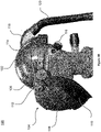
Figure 2 , there is shown a perspective, bottom view of thehelmet 100 shown inFigures 1A and1B . Theprotective shell 102 comprises anouter wall 101 and aninner wall 103. Theouter wall 101 is connected to theinner wall 103 by a plurality ofreinforcement structures 105. In other words, theprotective shell 102 comprises a double-walled structure. The double-walled structure may be used to receive the headband in a space between the inner andouter walls protective shell 102. To this end, theheadband 114 may comprise a plurality oftabs 134, each of which is received within a guide of the double-walled structure of theprotective shell 102. - The
face shield 104 is connected to the front of theprotective shell 102 via thepivot 106. Thepivot 106 extends between theouter wall 101 of theprotective shell 102 and an inner surface offace shield 104. - As mentioned above, the
face shield 104 comprises aface cover 110. Theface cover 110 is configured to cover a user's chin, neck and mouth. In the embodiment ofFigures 1A ,1B , and2 , theface shield 104 is a welding mask. Accordingly, theface cover 110 is made of a heat resistant material that can protect the user's face from sparks created during the welding process. Avisor 108 is pivotally attached to theface cover 110 as described above. - The
visor 108 may include an auto-darkening filter. When the user is not welding, the filter may be a relatively transparent, allowing good vision for job set up and torch positioning. As soon as an arc is struck, thevisor 108 may darken to a welding shade, thereby protecting the user's eyes form UV damage during the welding process. The welding shade of thevisor 108 may be adjustable, lighter or darker. When the user interrupts the welding process, thevisor 108 may automatically return to a its initial, relatively transparent condition. - A
head pad 130 is suspended within theprotective shell 102 of thehelmet 100. In other words, thehead pad 130 is received within a concave portion of theprotective shell 102 and is distanced from an inner surface of theinner wall 103 of theprotective shell 102. - In the embodiment of
Figure 2 , thehead pad 130 is suspended within theprotective shell 102 by means ofstraps headband 114. Between their ends, the straps are threaded through slots of thepad 130, so as to hold thepad 130 centrally within theprotective shell 102. As will be understood, the length of thestraps head pad 130 does not contact the inner surface of theinner wall 103, when being suspended by thestraps - The
head pad 130 is made of a high-friction material. In other words, the material of the head pad is constructed to provide a secure friction fit between the pad and the user's head, such that the helmet is prevented from shifting to the front or rear of the user's head. The head pad is made of a polymeric material, such as rubber or silicone. - The
head pad 130 shown inFigure 2 comprises a plurality ofprotrusions 132. Theprotrusions 132 extend over afirst surface 136 of the head pad. Thefirst surface 136 faces away from theprotective shell 102 and is adapted to contact the user's head, when in use. In particular, it is theprotrusions 132 that will contact the user's head, when in use. In the embodiment ofFigure 2 , thehead pad 130 is a single piece, i.e. thefirst surface 136 and theprotrusions 132 are a unitary part and made from the same material. Accordingly, theprotrusions 132 may also be made from rubber or silicone providing theprotrusions 132 with elasticity. Theelastic protrusions 132 will increase the friction between the user's head and the head pad. Accordingly, the protrusions will further prevent thehelmet 100 from slipping across the user's head. - It will be appreciated that the
protrusions 132 may similarly be made from a different material to the head pad. However, theprotrusions 132 should always be made from a material that provides some elasticity to counteract any potential movement of thehelmet 100 with respect to the user's head. -
Figure 2 further shows anairduct 140 that is arranged along the inner surface of theinner wall 103. Theairduct 140 extends between the air inlet 118 (Figures 1A and1B ) and anair outlet 142. Theair outlet 142 is arranged at a front end of theprotective shell 102. Accordingly, the air outlet is arranged such that forced air flowing into theairduct 140 via theair inlet 118 is directed towards theface shield 104, thereby supplying the user with a constant flow of fresh air. It will be understood that such anairduct 140 is an optional feature that may only be required if the helmet is used as part of a PAPR kit. - Turning to
Figures 3A and 3B , there is shown another embodiment of ahead pad 200. Thehead pad 200 may be installed within a helmet, such as the helmet shown inFigures 1A ,1B , and2 , e.g. by means of one or more straps. Thehead pad 200 comprises sixopenings first opening 204 and afourth opening 210, a second strap may extend through asecond opening 206 and afifth opening 212 and a third strap may extend through athird opening 208 and asixth opening 214. Accordingly, theopenings 204 to 214 may be used to suspend the pad within the protective shell of a corresponding helmet by means of a plurality of straps. - The
pad 200 comprises afirst surface 202. Thehead pad 200 is arranged to be installed inside the cavity of a helmet in such a way that thefirst surface 202 faces away from the protective shell. A plurality ofprotrusions 216 are arranged on and protrude over thefirst surface 202. -
Figure 3B shows an enlarged view of the protrusions of thepad 200 shown inFigure 3A . In some embodiments, the centres of adjacent protrusion 216A, 216B may be distanced from each other by adistance 218 by up to 10mm. In other words, adjacent protrusions 216A, 216B may be separated from each other by a gap of up to 10mm. Theprotrusions 216 of the embodiment shown inFigures 3A and 3B have a cylindrical shape. However, any other shape may be feasible that allows the protrusions to extend over thefirst surface 202. Thecylindrical protrusions 216 shown inFigures 3A and 3B may have adiameter 220 below 10mm. The protrusions may further have a height of up to 10mm. The height of the protrusions refers to the distance between the first surface and the tip of the protrusions. - The listing or discussion of an apparently prior-published document in this specification should not necessarily be taken as an acknowledgement that the document is part of the state of the art or is common general knowledge.
- Preferences and options for a given aspect, feature or parameter of the disclosure should, unless the context indicates otherwise, be regarded as having been disclosed in combination with any and all preferences and options for all other aspects, features and parameters of the disclosure.
Claims (15)
- A helmet comprising:- a protective shell;- a face shield and/or optical device connected to the protective shell; and- a head pad arranged inside the protective shell such that the pad is substantially centred on a user's head, when in use, said head pad comprising a first surface facing away from the protective shell and adapted to contact a user's head, when in use, the first surface comprising a plurality of protrusions,wherein the protrusions are made of an elastic material.
- The helmet of Claim 1,
wherein the head pad is made of an elastic material. - The helmet of Claim 1 or 2,
wherein the head pad is made of a polymeric material, particularly rubber or silicone, that provides a friction fit between the head pad and a user's head, when in use. - The helmet of any one of Claims 1 to 3,
wherein the protrusions are substantially cylindrical in shape. - The helmet of any one of Claims 1 to 4,
wherein the protrusions have a diameter below 10mm and/or wherein the protrusions have a height below 10mm, and/or wherein adjacent protrusions are spaced by a gap of up to 10mm. - The helmet of any one of Claims 1 to 5,
wherein the head pad has a thickness of 0 to 10mm. - The helmet of any one of Claims 1 to 6,
wherein the head pad has a substantially circular, oval, square, or rectangular shape. - The helmet of any one of Claims 1 to 7,
wherein the head pad comprises a second surface facing an inner surface of the protective shell, said second surface being spaced from the inner surface of the protective shell. - The helmet of any one of Claims 1 to 8,
wherein the head pad is suspended by a harness arranged inside the protective shell and configured to secure the protective shell to a user's head, when in use. - The helmet of Claim 9,
wherein the harness further includes a plurality of straps connecting the head pad to the protective shell, and/or wherein the head pad comprises a plurality of openings, and wherein each of the plurality of straps extends through at least one of the openings, and/or wherein the harness further comprises a headband connected to the plurality of straps. - The helmet of any one of Claims 1 to 10,
wherein the face shield is a visor for welding. - The helmet of any one of Claims 1 to 11,
wherein the face shield is pivotably attached to the protective shell and transferrable between an active and an inactive position. - The helmet of any one of Claims 1 to 12,
wherein the helmet comprises an airduct having an outlet at a front end of the protective shell and an inlet at rear end of the protective shell, the inlet being adapted for removably connecting an air supply hose. - The helmet of any one of Claims 1 to 13,
wherein the helmet is a safety helmet or a military helmet. - A PAPR kit comprising:- a helmet according to any one of Claims 1 to 14;- an air blower unit for generation of forced air flow; and- an air supply hose for supply of forced air flow from the air blower unit to the helmet.
Applications Claiming Priority (1)
| Application Number | Priority Date | Filing Date | Title |
|---|---|---|---|
| GB2101764.5A GB2605354A (en) | 2021-02-09 | 2021-02-09 | Helmet |
Publications (1)
| Publication Number | Publication Date |
|---|---|
| EP4039117A1 true EP4039117A1 (en) | 2022-08-10 |
Family
ID=74879133
Family Applications (1)
| Application Number | Title | Priority Date | Filing Date |
|---|---|---|---|
| EP22155299.5A Withdrawn EP4039117A1 (en) | 2021-02-09 | 2022-02-07 | Helmet |
Country Status (2)
| Country | Link |
|---|---|
| EP (1) | EP4039117A1 (en) |
| GB (1) | GB2605354A (en) |
Cited By (1)
| Publication number | Priority date | Publication date | Assignee | Title |
|---|---|---|---|---|
| FR3154903A1 (en) | 2023-11-08 | 2025-05-09 | Delta Plus Group | Helmet with support device and force absorber |
Citations (3)
| Publication number | Priority date | Publication date | Assignee | Title |
|---|---|---|---|---|
| US20050138719A1 (en) * | 2003-04-29 | 2005-06-30 | Huh Moon Y. | Cushion pad structure for headband |
| KR20120138138A (en) * | 2011-06-14 | 2012-12-24 | 현대중공업 주식회사 | Safety helmet |
| WO2019079162A1 (en) * | 2017-10-16 | 2019-04-25 | Gentex Corporation | Modular respiratory protection system |
Family Cites Families (4)
| Publication number | Priority date | Publication date | Assignee | Title |
|---|---|---|---|---|
| US5121508A (en) * | 1991-02-19 | 1992-06-16 | Grilliot William L | Firefighter's helmet having head securing means |
| DE29904148U1 (en) * | 1999-03-08 | 1999-06-02 | Butt, Hans Jochen, 26197 Großenkneten | Helmet, especially motorcycle helmet |
| JP3905118B1 (en) * | 2006-06-21 | 2007-04-18 | 英生 住野 | helmet |
| CN212520957U (en) * | 2020-06-11 | 2021-02-12 | 润得科技(深圳)有限公司 | Warning device for safety helmet |
-
2021
- 2021-02-09 GB GB2101764.5A patent/GB2605354A/en active Pending
-
2022
- 2022-02-07 EP EP22155299.5A patent/EP4039117A1/en not_active Withdrawn
Patent Citations (3)
| Publication number | Priority date | Publication date | Assignee | Title |
|---|---|---|---|---|
| US20050138719A1 (en) * | 2003-04-29 | 2005-06-30 | Huh Moon Y. | Cushion pad structure for headband |
| KR20120138138A (en) * | 2011-06-14 | 2012-12-24 | 현대중공업 주식회사 | Safety helmet |
| WO2019079162A1 (en) * | 2017-10-16 | 2019-04-25 | Gentex Corporation | Modular respiratory protection system |
Cited By (2)
| Publication number | Priority date | Publication date | Assignee | Title |
|---|---|---|---|---|
| FR3154903A1 (en) | 2023-11-08 | 2025-05-09 | Delta Plus Group | Helmet with support device and force absorber |
| US12324472B2 (en) | 2023-11-08 | 2025-06-10 | Delta Plus Group | Helmet with holding device and force absorber |
Also Published As
| Publication number | Publication date |
|---|---|
| GB2605354A (en) | 2022-10-05 |
| GB202101764D0 (en) | 2021-03-24 |
Similar Documents
| Publication | Publication Date | Title |
|---|---|---|
| US5845341A (en) | Combination head and eye-protective apparatus and goggles | |
| JP4831923B2 (en) | Football helmet | |
| US9907348B2 (en) | Functional headband having integral cushion band | |
| US20070033716A1 (en) | Goggles with removable frame and methods of making and using the same | |
| CN106572715B (en) | protective helmet | |
| US5974593A (en) | Batting helmet with circumferential elastic head band | |
| US8225431B2 (en) | Head protective gear | |
| EP1452101A1 (en) | Protective helmet with vertically adjustable headband | |
| US20150033430A1 (en) | Face protector for welder | |
| US5113534A (en) | Firefighter's helmet having tilt adjustment | |
| ES2994572T3 (en) | Size adaptive protective headgear | |
| EP3154483A1 (en) | Protective headwear with airflow | |
| US11324274B2 (en) | Welding helmet | |
| EP2521465A1 (en) | Impact absorbing safety helmet for mining | |
| CN205321332U (en) | Novel safety helmet | |
| GB2605354A (en) | Helmet | |
| CN110868880B (en) | Protective headgear with air flow | |
| US20070016997A1 (en) | Safety hard hat and face shield assembly | |
| US11576454B1 (en) | Headgear with curved straps for welding helmet | |
| KR200479141Y1 (en) | Safety helmet | |
| CN216493705U (en) | Detachable light helmet | |
| US20250123082A1 (en) | Modular tactical helmet | |
| KR101670067B1 (en) | Safety helmet for safety checking for facility management | |
| JP3166090U (en) | Helmet-mounted occipital protector | |
| US20170216707A1 (en) | Goalie Helmet |
Legal Events
| Date | Code | Title | Description |
|---|---|---|---|
| PUAI | Public reference made under article 153(3) epc to a published international application that has entered the european phase |
Free format text: ORIGINAL CODE: 0009012 |
|
| STAA | Information on the status of an ep patent application or granted ep patent |
Free format text: STATUS: THE APPLICATION HAS BEEN PUBLISHED |
|
| AK | Designated contracting states |
Kind code of ref document: A1 Designated state(s): AL AT BE BG CH CY CZ DE DK EE ES FI FR GB GR HR HU IE IS IT LI LT LU LV MC MK MT NL NO PL PT RO RS SE SI SK SM TR |
|
| STAA | Information on the status of an ep patent application or granted ep patent |
Free format text: STATUS: REQUEST FOR EXAMINATION WAS MADE |
|
| 17P | Request for examination filed |
Effective date: 20230209 |
|
| RBV | Designated contracting states (corrected) |
Designated state(s): AL AT BE BG CH CY CZ DE DK EE ES FI FR GB GR HR HU IE IS IT LI LT LU LV MC MK MT NL NO PL PT RO RS SE SI SK SM TR |
|
| STAA | Information on the status of an ep patent application or granted ep patent |
Free format text: STATUS: EXAMINATION IS IN PROGRESS |
|
| 17Q | First examination report despatched |
Effective date: 20240626 |
|
| STAA | Information on the status of an ep patent application or granted ep patent |
Free format text: STATUS: THE APPLICATION IS DEEMED TO BE WITHDRAWN |
|
| 18D | Application deemed to be withdrawn |
Effective date: 20250103 |