EP4039111A1 - Electronic vaporization device and vaporizer thereof - Google Patents
Electronic vaporization device and vaporizer thereof Download PDFInfo
- Publication number
- EP4039111A1 EP4039111A1 EP19947639.1A EP19947639A EP4039111A1 EP 4039111 A1 EP4039111 A1 EP 4039111A1 EP 19947639 A EP19947639 A EP 19947639A EP 4039111 A1 EP4039111 A1 EP 4039111A1
- Authority
- EP
- European Patent Office
- Prior art keywords
- liquid
- liquid absorbing
- groove
- air outlet
- vaporization
- Prior art date
- Legal status (The legal status is an assumption and is not a legal conclusion. Google has not performed a legal analysis and makes no representation as to the accuracy of the status listed.)
- Granted
Links
Images







Classifications
-
- A—HUMAN NECESSITIES
- A24—TOBACCO; CIGARS; CIGARETTES; SIMULATED SMOKING DEVICES; SMOKERS' REQUISITES
- A24F—SMOKERS' REQUISITES; MATCH BOXES; SIMULATED SMOKING DEVICES
- A24F40/00—Electrically operated smoking devices; Component parts thereof; Manufacture thereof; Maintenance or testing thereof; Charging means specially adapted therefor
- A24F40/40—Constructional details, e.g. connection of cartridges and battery parts
- A24F40/48—Fluid transfer means, e.g. pumps
- A24F40/485—Valves; Apertures
-
- A—HUMAN NECESSITIES
- A24—TOBACCO; CIGARS; CIGARETTES; SIMULATED SMOKING DEVICES; SMOKERS' REQUISITES
- A24F—SMOKERS' REQUISITES; MATCH BOXES; SIMULATED SMOKING DEVICES
- A24F40/00—Electrically operated smoking devices; Component parts thereof; Manufacture thereof; Maintenance or testing thereof; Charging means specially adapted therefor
- A24F40/40—Constructional details, e.g. connection of cartridges and battery parts
- A24F40/42—Cartridges or containers for inhalable precursors
-
- A—HUMAN NECESSITIES
- A24—TOBACCO; CIGARS; CIGARETTES; SIMULATED SMOKING DEVICES; SMOKERS' REQUISITES
- A24F—SMOKERS' REQUISITES; MATCH BOXES; SIMULATED SMOKING DEVICES
- A24F40/00—Electrically operated smoking devices; Component parts thereof; Manufacture thereof; Maintenance or testing thereof; Charging means specially adapted therefor
- A24F40/10—Devices using liquid inhalable precursors
-
- A—HUMAN NECESSITIES
- A24—TOBACCO; CIGARS; CIGARETTES; SIMULATED SMOKING DEVICES; SMOKERS' REQUISITES
- A24F—SMOKERS' REQUISITES; MATCH BOXES; SIMULATED SMOKING DEVICES
- A24F40/00—Electrically operated smoking devices; Component parts thereof; Manufacture thereof; Maintenance or testing thereof; Charging means specially adapted therefor
- A24F40/30—Devices using two or more structurally separated inhalable precursors, e.g. using two liquid precursors in two cartridges
-
- A—HUMAN NECESSITIES
- A24—TOBACCO; CIGARS; CIGARETTES; SIMULATED SMOKING DEVICES; SMOKERS' REQUISITES
- A24F—SMOKERS' REQUISITES; MATCH BOXES; SIMULATED SMOKING DEVICES
- A24F40/00—Electrically operated smoking devices; Component parts thereof; Manufacture thereof; Maintenance or testing thereof; Charging means specially adapted therefor
- A24F40/40—Constructional details, e.g. connection of cartridges and battery parts
-
- A—HUMAN NECESSITIES
- A24—TOBACCO; CIGARS; CIGARETTES; SIMULATED SMOKING DEVICES; SMOKERS' REQUISITES
- A24F—SMOKERS' REQUISITES; MATCH BOXES; SIMULATED SMOKING DEVICES
- A24F40/00—Electrically operated smoking devices; Component parts thereof; Manufacture thereof; Maintenance or testing thereof; Charging means specially adapted therefor
- A24F40/40—Constructional details, e.g. connection of cartridges and battery parts
- A24F40/48—Fluid transfer means, e.g. pumps
Definitions
- the present disclosure relates to vaporization apparatuses, and more specifically, to an electronic vaporization apparatus and a vaporizer thereof.
- An electronic vaporization apparatus is generally configured to heat and vaporize e-liquid stored in the electronic vaporization apparatus and form vapor for a user to inhale, and the user generally inhales the vapor by using an air outlet channel in an airflow channel of the electronic vaporization apparatus.
- the vapor may be partially condensed when encountering a sidewall of the air outlet channel to form a condensate, and if the condensate is not processed, the user may easily inhale the condensate into a mouth, thereby affecting user experience.
- a technical problem to be resolved by the present disclosure is to provide an improved vaporizer and further provide an improved electronic vaporization apparatus.
- a technical solution adopted by the present disclosure to resolve the technical problem thereof is to provide a vaporizer, including a vaporization component and an air outlet channel, wherein during inhaling of a user, vapor formed by the vaporization component reaches a mouth of the user through the air outlet channel, wherein an inner sidewall of the air outlet channel is provided with at least one first liquid absorbing groove, and wherein the first liquid absorbing groove is configured to absorb condensed liquid formed on the inner sidewall of the air outlet channel through capillary force.
- the air outlet channel includes a first end close to the vaporization component and a second end away from the vaporization component, the first liquid absorbing groove extends from the first end of the air outlet channel to the second end of the air outlet channel, and the condensed liquid absorbed by the first liquid absorbing groove flows to the vaporization component by gravity.
- a central axis of the first liquid absorbing groove and a central axis of the air outlet channel are parallel.
- the first liquid absorbing groove is spirally disposed.
- the vaporization component is configured to vaporize the condensed liquid flowing from the first liquid absorbing groove again.
- the vaporizer further includes a vaporization cavity, and the first liquid absorbing groove is in direct communication with the vaporization cavity.
- a plurality of first liquid absorbing grooves are provided, and the plurality of first liquid absorbing grooves are disposed at intervals and parallel to each other.
- a groove depth of each first liquid absorbing groove gradually decreases in a direction away from the second end.
- a groove width of each first liquid absorbing groove gradually increases in a direction away from the second end.
- a groove depth of each first liquid absorbing groove is greater than or equal to 0.1 mm.
- a groove width of each first liquid absorbing groove is 0.05 mm to 1 mm.
- a groove width of each first liquid absorbing groove gradually increases in a direction from a bottom to an opening of the respective first liquid absorbing groove.
- the vaporizer further includes a housing and a base, where the housing is sleeved on the base, the vaporization component is disposed on the base, and a sidewall of the air outlet channel and the housing are integrally formed.
- the housing includes a body and an air outlet tube longitudinally disposed in the body; the air outlet channel is disposed in the air outlet tube; the at least one first liquid absorbing groove is disposed on an inner sidewall of the air outlet tube; and an inner side of the body and an outside of the air outlet tube form a liquid storage cavity in fluid connection to the vaporization component.
- the present disclosure further constructs an electronic vaporization apparatus, including a vaporization component and an air outlet channel; wherein during inhaling of a user, vapor formed by the vaporization component reaches a mouth of the user through the air outlet channel; and wherein an inner sidewall of the air outlet channel is provided with at least one first liquid absorbing groove, and the first liquid absorbing groove is configured to absorb condensed liquid formed on the inner sidewall of the air outlet channel through capillary force.
- the air outlet channel includes a first end close to the vaporization component and a second end away from the vaporization component, the first liquid absorbing groove extends from the first end of the air outlet channel to the second end of the air outlet channel, and the condensed liquid absorbed by the first liquid absorbing groove flows to the vaporization component by gravity.
- a central axis of the first liquid absorbing groove and a central axis of the air outlet channel are parallel.
- the first liquid absorbing groove is spirally disposed.
- the vaporization component is configured to vaporize the condensed liquid flowing from the first liquid absorbing groove again; and the vaporizer further includes a vaporization cavity, and the first liquid absorbing groove is in direct communication with the vaporization cavity.
- a groove depth of each first liquid absorbing groove is set as gradually decreases in a direction away from the second end;
- Implementation of the electronic vaporization apparatus and the vaporizer of the present disclosure has the following beneficial effects: in the vaporizer, at least one first liquid absorbing groove is opened on the inner sidewall of the air outlet channel, and the first liquid absorbing groove absorbs condensed liquid formed on the sidewall of the air outlet channel through capillary force, to further prevent the condensed liquid from being inhaled by a user into a mouth, thereby improving user experience.
- the electronic vaporization apparatus has advantages such as high user experience and low manufacturing costs.
- orientation limitation the upper, lower, top, and bottom orientations shown in the accompanying drawings are the upper, lower, top, and bottom of the present disclosure. It should be understood that orientation or position relationships indicated by “upper” and “lower” are based on orientation or position relationships shown in the accompanying drawings or constructed and operated in specific orientations, and are used only for ease of description of the technical solution, rather than indicating or implying that the mentioned apparatus or element needs to have a particular orientation. Therefore, such terms should not be construed as limiting of the present disclosure.
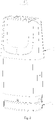
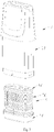
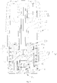
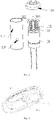
- FIG. 1 to FIG. 4 show a first embodiment of an electronic vaporization apparatus according to the present disclosure.
- the electronic vaporization apparatus is applicable to vaporization of a liquid medium such as e-liquid or medicine, and includes a vaporizer and a power supply apparatus mechanically and electrically connected to the vaporizer.
- the vaporizer is configured to heat and vaporize a liquid medium
- the power supply apparatus is configured to supply power to the vaporizer.
- the vaporizer and the power supply apparatus are detachably connected to each other.
- the power supply apparatus includes a power supply housing, a battery disposed in the power supply housing, a conductive contact disposed in the power supply housing and connected to the battery and the vaporizer, and a control circuit disposed in the power supply housing and electrically connected to the battery and the vaporizer.
- the vaporizer includes a housing 10, a base 20, a vaporization component 30, a first sealing element 40, an air-liquid balancing element 50, and a liquid guiding element 60.
- the housing 10 is sleeved on an outside of the vaporization component 30, and an inner side of the housing is configured to form a liquid storage cavity 111 for accommodating the liquid medium.
- the liquid medium is e-liquid.
- the base 20 is provided for mount the vaporization component 30, and the housing 10 is sleeved on the base 20.
- the vaporization component 30 is disposed in the housing 10 and located on the base 20.
- the first sealing element 40 is disposed on the base 20 and configured to seal a junction between the vaporization component 30 and the base 20.
- the air-liquid balancing element 50 is disposed in a body 11 and located at a lower part of the liquid storage cavity 111, sleeved on the outside of the vaporization component 30, and located on the base 20.
- the air-liquid balancing element 50 connects the liquid storage cavity 111 to the outside, to balance air pressure in the liquid storage cavity 111.
- a quantity of the liquid guiding elements 60 may be two, and it may be understood that, in some other embodiments, the quantity of the liquid guiding elements may be one or more.
- the liquid guiding element 60 runs through the air-liquid balancing element 50 and is configured to cause the liquid storage cavity 111 to be in fluid connection to the vaporization component 30, to provide a liquid medium for the vaporization component 30. It may be understood that, in some other embodiments, the air-liquid balancing element 50 and the liquid guiding element 60 may be omitted.
- the housing 10 includes a body 11 and an air outlet tube 12; and the body 11 and the air outlet tube 12 are integrally formed through injection molding. It may be understood that, in some other embodiments, the air outlet tube 12 and the body 11 form split structures.
- the body 11 is sleeved on the base 20 and the vaporization component 30, a space is reserved between the body and an upper part of the vaporization component 30, and the space is used for forming the liquid storage cavity 111.
- the air outlet tube 12 is disposed in the body 11 in a longitudinal direction and is disposed in communication with the vaporization component 30, and the air outlet tube 12 is located at a central axis of the body 11.
- the air outlet tube 12 is disposed on one side of the body 11 and not limited to the central axis, and the air outlet tube 12 may be also disposed obliquely.
- An inner side of the air outlet tube 12 forms an air outlet channel 121, the air outlet channel 121 is disposed in an axial direction of the air outlet tube 12, and a sidewall of the air outlet tube and the housing are integrally formed.
- vapor may reach a mouth of the user through the air outlet channel 121.
- a second end 1212 of the air outlet channel 121 is inserted into the vaporization component 30, and a first end 1211 thereof forms a mouthpiece for the user to inhale vapor.
- An inner sidewall of the air outlet channel 121 is provided with at least one first liquid absorbing groove 122.
- the at least one first liquid absorbing groove 122 may be a plurality of first liquid absorbing grooves 122. It may be understood that, in some other embodiments, there may be a plurality of first liquid absorbing grooves 121, but the quantity is not limited thereto and may also be one.
- the first liquid absorbing groove 122 includes capillary force used for absorbing condensed liquid formed on the sidewall of the air outlet channel 121 through condensation, the condensed liquid flows onto the vaporization component 30 under action of gravity, and the vaporization component 30 vaporizes the condensed liquid flowing from the first liquid absorbing groove 122 again, to improve utilization of the liquid medium.
- the plurality of first liquid absorbing grooves 122 are disposed on an inner sidewall of the air outlet tube 12 and disposed at intervals in a circumferential direction of the air outlet channel 121.
- the first liquid absorbing groove 122 may absorb the condensed liquid into the groove through capillary force.
- the first liquid absorbing groove 122 is disposed longitudinally along the air outlet channel 121 and extends from the second end 1212 of the air outlet channel 121 to the first end 1211 of the air outlet channel 121.
- the first liquid absorbing groove is parallel to a central axis of the air outlet channel 121 and is in fluid connection to the vaporization component 30 in the vaporization component 30, so that the condensed liquid flows to the upper of the vaporization component 30 in a direction of the first liquid absorbing groove 122 under the action of gravity and drips on the vaporization component 30 to be vaporized again, thereby improving the utilization of the liquid medium, preventing the liquid medium from being inhaled into the mouth of the user, and improving user experience.
- the first liquid absorbing groove is not limited to being disposed longitudinally, and may be disposed spirally or obliquely.
- an end surface of the first end 1211 of the air outlet channel 121 is provided with an outlet 1221.
- the outlet 1221 is in communication with the first liquid absorbing groove 122 and the vaporization component 30, and liquid in the first liquid absorbing groove 122 drips onto the vaporization component 30 through the outlet 1221.
- a groove depth of the first liquid absorbing groove 122 is disposed as gradually decreasing in a direction away from the outlet 1221, and a bottom surface of the first liquid absorbing groove 122 is a slope tilting to a direction of the outlet 1221.
- each first liquid absorbing groove 122 may be greater than or equal to 0.1 mm.
- a groove width of each first liquid absorbing groove 122 is set as gradually increasing in an opening direction of the first liquid absorbing groove 122, so that the first liquid absorbing groove 122 presents a characteristic that an inner part of is narrow and an opening is wide, thereby helping the liquid flow onto the vaporization component 30 along the first liquid absorbing groove 122.
- the width of each liquid absorbing groove 122 may be 0.05 mm to 1 mm.
- the base 20 includes a base body 21, a support component 22 disposed on the base body 21, and a liquid storage structure 23.
- a shape and a size of a cross section of the base body 21 match a shape and a size of an opening end of the housing 10, and the base body is configured to seal the opening of the housing 10.
- a groove 211 is opened on the base 20.
- the groove 211 is disposed on one side of the base body 21 disposed opposite to a vaporization cavity 311 of the vaporization component 30, for ease of forming the liquid storage structure 23 at a bottom of the vaporization cavity 311;
- the support component 22 includes two groups of support pillars disposed at intervals; and the two groups of support pillars are respectively located on two opposite sides of the groove 211 for supporting a vaporization element 32 in the vaporization component 30.
- the liquid storage structure 23 is disposed in the groove 211 and in communication with the vaporization cavity 311 of the vaporization component 30, and is configured to store a liquid medium to prevent the liquid medium from being leaked out.
- the liquid storage structure 23 includes a plurality of second liquid absorbing grooves 231, a liquid diverging groove 232, and a plurality of liquid guiding grooves 233.
- the plurality of second liquid absorbing grooves 231 are disposed at intervals and in parallel at a bottom of the groove 211, the second liquid absorbing groove 231 and the vaporization cavity 311 are disposed opposite to each other, and the second liquid absorbing groove has capillary force, which can absorb a liquid medium dripped from the vaporization cavity 311 or the air outlet channel 121.
- the liquid diverging groove 232 is located on a bottom surface of the groove 211 and disposed intersecting with the plurality of second liquid absorbing grooves 231.
- the liquid diverging groove crosscuts the second liquid absorbing grooves 231 and is in communication with the liquid absorbing grooves 231 for liquid diverging and absorbing the liquid medium more quickly.
- the plurality of liquid guiding grooves 233 are disposed on a sidewall of the groove 211 at intervals.
- the liquid guiding grooves are disposed corresponding to the second liquid absorbing grooves 231 and the liquid diverging groove 232 and are in communication with the second liquid absorbing grooves 231 and the liquid diverging groove 232, and includes capillary force for pouring liquid into the second liquid absorbing grooves 231.
- each second liquid absorbing groove 231 is transversely disposed in an extending manner along the bottom surface of the groove 211, namely, transversely disposed in an extending manner along the vaporization cavity 311.
- the second liquid absorbing groove controls a flow direction of the liquid medium to effectively prevent liquid leakage.
- a groove width of the second liquid absorbing groove 231 is 0.05 mm to 1 mm.
- a groove depth of each second liquid absorbing groove 231 is greater than 0.1 mm, and it may be understood that, in some other embodiments, the groove depth of the second liquid absorbing groove 231 is also equal to 0.1 mm.
- the liquid diverging groove 232 is disposed perpendicular to each second liquid absorbing groove 231, and divides each second liquid absorbing groove 231 into two sections.
- a width of the liquid diverging groove 232 is greater than the width of second liquid absorbing groove 231, for ease of improving a liquid absorbing speed, thereby preventing the liquid medium from penetrating to the outside from pores of an electrode.
- the liquid guiding grooves 233 are disposed on the sidewall of the groove 211 and longitudinally extend along the base 20, and each second liquid absorbing groove 231 is in communication with each liquid diverging groove 232 correspondingly, to guide the liquid medium into the second liquid absorbing grooves 231 and the liquid diverging groove 232.
- an opening of one end of the liquid guiding groove 233 away from the second liquid absorbing groove 231 and the liquid diverging groove 232 is disposed on an outer side of the vaporization cavity 311 for absorbing leaked liquid on the outer side of the vaporization cavity 311.
- an inner sidewall of the groove 211 is provided with a stage 2111, and the stage is configured to fit and assemble with a vaporization housing 31 of the vaporization component 30, to improve the assembly tightness.
- the liquid guiding groove 233 includes capillary force for absorbing leaked liquid and guiding the leaked liquid into the second liquid absorbing groove 231.
- a groove width of the liquid guiding groove 233 may be 0.05 mm to 1 mm, and it may be understood that, in some other embodiments, the groove width of the liquid guiding groove 233 is not limited to 0.05 mm to 1 mm.
- the vaporization component 30 includes a vaporization housing 31 and a vaporization element 32; and the vaporization housing 31 is sleeved on the base 20 and inserted into the groove 211.
- the vaporization housing 31 is configured to mount the vaporization element 32 to fix the vaporization element 32; an inner side of the vaporization housing 31 forms the vaporization cavity 311; and the vaporization cavity 311 is located on the base 20 and in direct communication with the first liquid absorbing groove 122.
- Liquid leakage may easily occur at a place where the vaporization housing 31 is in contact with the vaporization element 32, the liquid medium may be leaked out easily from a junction of the first sealing element 40 and the vaporization housing 31, and the opening of the end of the liquid guiding groove 233 away from the second liquid absorbing groove 231 and the liquid diverging groove 232 is disposed opposite to the junction of the vaporization housing 31 and the first sealing element 40. Specifically, the opening directly faces the junction and absorbs leaked liquid at this place through capillary force.
- the vaporization element 32 transversely runs through the vaporization housing 31, and the vaporization element 32 includes a vaporization core 321 running through the vaporization housing 31 and a heating element 322 wound on the vaporization core 321.
- the vaporization core 321 may be a cotton core, and two ends of the vaporization core 321 are located on the two groups of support pillars on the base body 211 and in fluid connection to the liquid guiding element 60.
- a conductive connection portion of the heating element 322 runs through the base 20 to be connected to an electrode 90.
- the heating element 322 may be a heating wire.
- the first sealing element 40 is sleeved on the base 20 and sleeved on an outside of the vaporization housing 31.
- the first sealing element 40 may be a sealing sleeve.
- the sealing sleeve may be a silicone sleeve or rubber sleeve. It may be understood that, in some other embodiments, the sealing sleeve is not limited to the silicone sleeve or the rubber sleeve.
- the air-liquid balancing element 50 is in a shape of a cylinder. Specifically, A cross section thereof is an oval or rectangular cylinder, and a peripheral thereof and an inner wall surface of the housing 10 may be combined in an interference fitting manner, to seal the liquid storage cavity 111.
- the air-liquid balancing element 50 includes two through holes 51, a liquid storage ventilation structure 52 located on the peripheral of the through hole 51, and an airflow channel 53 located between the two through holes 51.
- the through hole 51 is provided for the liquid guiding element 60 to run through
- the liquid storage ventilation structure 52 is configured to communicate the liquid storage cavity 111 with the outside, to balance air pressure in the liquid storage cavity 111, and includes a plurality of liquid storage grooves 521 disposed in parallel and generating capillary force to the liquid medium and two air return grooves.
- the liquid storage groove is configured to store liquid and prevent liquid leakage.
- the air return groove is disposed longitudinally and crosscuts the liquid storage groove 521 and communicates the liquid storage groove 521 with the liquid storage cavity 111, and the air return groove is provided for air to enter the liquid storage cavity 111.
- the airflow channel 53 is in communication with the air outlet channel 121, for ease of communicating the air outlet channel 121 with the vaporization cavity 311.
- a temperature ventilation process is formed by disposing the air-liquid balancing element 60, to prevent fried oil and burned taste caused by lacking of ventilation for a long time (insufficient liquid supply) and large-particle liquid dripping and liquid leakage caused by abrupt large amount of ventilation (excessive liquid supply).
- an independent ventilation channel is formed to seal structure gaps, to prevent liquid leakage caused by capillary force of the gaps and environment changes, and leaked liquid and condensed liquid may be prevented from being inhaled out, thereby improving a product yield rate.
- the liquid guiding element 60 is disposed corresponding to the through holes 51 on the air-liquid balancing element 50, runs through the through holes 51, located on two ends of the vaporization core 321, and in fluid connection to the vaporization core 321.
- the liquid guiding element 60 may be a cotton core, and it may be understood that, in some other embodiments, the liquid guiding element 60 is not limited to the cotton core.
- the vaporizer further includes a fixing sleeve 70; and the fixing sleeve 70 helps fix the conductive connection portion of the heating element 322, for ease of positioning of the conductive connection portion of the heating element 322.
- the conductive connection portion of the heating element 322 runs through the fixing sleeve 70.
- the fixing sleeve 70 is provided with a through hole 71 in communication with the vaporization cavity 311, and the through hole 71 is disposed longitudinally and in communication with the air outlet channel 121, for ease of air circulation.
- the fixing sleeve 70 may be a silicone sleeve. It may be understood that, in some other embodiments, the fixing sleeve 70 may be omitted.
- the vaporizer further includes a second sealing element 80; and the second sealing element 80 may be a sealing sleeve sleeved on the air-liquid balancing element 50, and is provided with a relief hole disposed corresponding to the liquid guiding element 60 and the air outlet channel 121.
- the second sealing element 80 may be a silicone sleeve or rubber sleeve.
- the vaporizer further includes an electrode 90.
- the electrode 90 includes two electrode terminals.
- the two electrode terminals are respectively a positive terminal and a negative terminal, which are disposed on the base body 211 in parallel.
- One end of the electrode is connected to the conductive connection portion of the heating element 322 by disposing a lead wire, and the other end is electrically connected to the power supply apparatus.
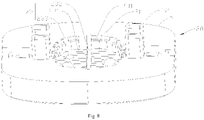
- FIG. 9 to FIG. 12 show a second embodiment of a vaporizer of the present disclosure.
- the present disclosure constructs a vaporizer, including a base 20, a housing 10 sleeved on the base 20 and connected to the base 20 in a sealing manner to form a liquid storage cavity 111, an electrode 90 disposed on a bottom of the base 20, a liquid injection component 109 mounted on the base 20 and injecting liquid to the liquid storage cavity 111, a vaporizer body disposed on the base 20, an airflow channel running through the entire vaporizer, and a liquid absorbing structure 101.
- the base includes a liquid storage structure, and for the liquid storage structure, reference may be made to the first embodiment, which is not described herein again.
- the vaporizer body includes a vaporization component 30, and the airflow channel includes an air inlet channel 131, a vaporization cavity 311, and an air outlet channel 121.
- the liquid absorbing structure 101 is disposed in the air outlet channel 121, a plurality of liquid storage grooves 105 are disposed in a circumferential direction of the liquid absorbing structure 101, and the liquid storage groove 105 absorbs condensed liquid in the air outlet channel 121 and/or e-liquid that is not completely vaporized in an inhaling process through capillary force.
- a material of the liquid absorbing structure 101 is one or more of PETG, PCTG, and PC.
- the liquid absorbing structure 101 includes a plurality of fins 104.
- the fins 104 are longitudinally disposed in parallel and at intervals, and a liquid storage groove 105 is formed between every two adjacently disposed fins 104.
- a width of the liquid storage groove 105 is small enough to generate capillary force to the condensed liquid, so that liquid drips carried in vapor generated in an inhaling process may stay in the liquid storage groove 105 due to the structure of the fins 104, thereby forming a liquid film in the liquid storage groove 105 and further being stored in the liquid storage groove 105, and preventing leaked liquid from being inhaled.
- the vaporization component 30 includes a cylinder-shaped vaporization core 321, a liquid guiding cotton 323 surrounding the vaporization core 321, and a heating element 322 wound on the vaporization core 321.
- a conductive connection portion of the heating element 322 runs through the base 20 to be connected to the electrode 90.
- the heating element 322 may be a heating wire.
- the vaporization core 321 absorbs e-liquid in the liquid storage cavity 111, and the heating element 322 is powered on and generates heat, to vaporize the e-liquid in the vaporization core 321.
- a user inhales vapor through an inhaling opening of a top cover of the vaporizer, air enters the vaporization core 321 through the air inlet channel 131 under action of suction force and is mixed with the vaporized e-liquid in the vaporization core 321, and is then exhausted from the inhaling opening of the top cover of the vaporizer after passing through the air outlet channel 121.
- the liquid absorbing structure 101 includes a plurality of fins 104.
- the fins 104 are longitudinally disposed in parallel or not in parallel and at intervals, and a liquid storage groove 105 is formed between every two adjacently disposed fins 104.
- a width of the liquid storage groove 105 is small enough to generate capillary force to the condensed liquid, so that liquid drips carried in vapor generated in an inhaling process may stay in the liquid storage groove 105 due to the structure of the fins 104, thereby forming a liquid film in the liquid storage groove 105 and further being stored in the liquid storage groove 105, and preventing leaked liquid from being inhaled.
- a thickness of the fin 104 and a width of the liquid storage groove 105 are 0.1 mm to 0.5 mm, and preferably, 0.15 mm to 0.3 mm.
- the liquid absorbing structure 101 includes: at least one liquid reflux groove 106 extending longitudinally.
- the at least one liquid reflux groove 106 longitudinally cuts at least a part of the liquid storage groove 105, and the liquid reflux groove 106 is used for guiding, when an amount of the e-liquid accumulated in the liquid storage groove 105 is excessive, the e-liquid to reflux to the vaporization core 321 along the liquid reflux groove 106 to be vaporized again.
- liquid reflux grooves 106 on the same diameter are disposed on an inner wall of the liquid absorbing structure 101, the liquid reflux groove 106 longitudinally cuts from a next fin 104 of a top fin 104 of the liquid absorbing structure 101 to a bottom fin 104, and the top fin 104 of the liquid absorbing structure 101 is configured to prevent condensed liquid in the liquid reflux groove 106 from flowing to the air outlet channel 121.
- a length by which the bottom fin 104 of the liquid absorbing structure 101 extends to a central axis of the liquid absorbing structure 101 is less than a length by which an adjacent fin 104 extends to the central axis.
- the air outlet channel 121 and the vaporization component 30 are disposed adjacent to each other in a longitudinal direction, the liquid absorbing structure 101 and the air outlet channel 121 are an integral structure, and the liquid storage groove 105 is opened on an inner wall surface of the air outlet channel 121.
- the liquid absorbing structure 101 and the air outlet channel 121 are split structures.
- the liquid absorbing structure 101 includes a cylinder-shaped body disposed right above the vaporization component 30, the housing 10 includes a body and an air outlet tube 12 longitudinally disposed in an inner cavity of the body, and an air inlet channel 131, a vaporization cavity 311, and an inner cavity of the liquid absorbing structure 101 and the air outlet tube 12 form a complete airflow channel.
- a reason for disposing the liquid absorbing structure 101 right above the vaporization core 321 and adjacent to the vaporization core 321 is that: when an e-cigarette is heated, since there is an e-liquid film during vaporization, bubbles generated in the vaporization process may easily bring e-liquid that is completely vaporized out; and when vapor rises, the liquid absorbing structure located right above the vaporization core 321 absorbs the liquid drips carried in the vapor and stores the liquid drips in the liquid storage groove, thereby greatly reducing a possibility of inhaling leaked liquid.
- the plurality of fins 104 are disposed on an inner wall surface of the cylinder-shaped body.
- the cylinder-shaped body includes a first part 102 and a second part (not shown in the figure) that may be detachably enclosed together, where an inner wall surface of the first part 102 is provided with a plurality of first fins, and an inner wall surface of the second part is provided with a plurality of second fins.
- the liquid absorbing structure is in a shape of a cylinder and may be formed by two semicircular cylinders through combination, and the fin is in a shape of a sector ring.
- the vaporization component 30 and the liquid absorbing structure 101 may be alternatively disposed in the same sleeve 107.
- the liquid absorbing structure 101 and the vaporization component 30 are disposed adjacent to each other, and the sleeve 107 corresponding to the vaporization component 30 is provided with at least liquid inlet 110 configured to cause the e-liquid in the liquid storage cavity 111 to enter the vaporization core 321.
- an outer sidewall of the liquid absorbing structure 101 and an inner sidewall of the sleeve 107 are disposed attached to each other.
- the liquid absorbing structure 101 and the sleeve 107 may be an integral structure.
- the sleeve 107 corresponding to the top of the liquid absorbing structure 101 is provided with a sealing element 108 connected to the air outlet channel 121 in a sealing manner, and the sealing element may be a silicone sleeve or a rubber sleeve. It may be understood that, in some other embodiments, the sealing sleeve is not limited to the silicone sleeve or the rubber sleeve.
- the present disclosure further constructs an electronic vaporization apparatus, including a base 20, a housing 10 sleeved on the base 20 and connected to the base 20 in a sealing manner to form a liquid storage cavity 111, an electrode 90 disposed on a bottom of the base 20, a liquid injection component 109 mounted on the base 20 and injecting liquid to the liquid storage cavity 111, a vaporizer body disposed on the base 20, an airflow channel running through the entire vaporizer, and a liquid absorbing structure 101.
- the vaporizer body includes a vaporization component 30, and the airflow channel includes an air inlet channel 131, a vaporization cavity 311, and an air outlet channel 121.
- the liquid absorbing structure 101 is disposed in the air outlet channel 121, a plurality of liquid storage grooves 105 are disposed in a circumferential direction of the liquid absorbing structure 101, and the liquid storage groove 105 absorbs condensed liquid in the air outlet channel 121 and/or e-liquid that is not completely vaporized in an inhaling process through capillary force.
- a material of the liquid absorbing structure 101 is one or more of PETG, PCTG, and PC.
- the electronic vaporization apparatus is a disposable vaporization apparatus in which the base, the housing, and the vaporizer body are an integral structure, or may be a vaporization apparatus in which the base, the housing, the vaporizer body are split structures.
- the liquid absorbing structure 101 includes a plurality of fins 104.
- the fins 104 are longitudinally disposed in parallel and at intervals, and a liquid storage groove 105 is formed between every two adjacently disposed fins 104.
- a width of the liquid storage groove 105 is small enough to generate capillary force to the condensed liquid, so that liquid drips carried in vapor generated in an inhaling process may stay in the liquid storage groove 105 due to the structure of the fins 104, thereby forming a liquid film in the liquid storage groove 105 and further being stored in the liquid storage groove 105, and preventing leaked liquid from being inhaled.
- the vaporization component 30 includes a cylinder-shaped vaporization core 321, a liquid guiding cotton 323 surrounding the vaporization core 321, and a heating element 322 wound on the vaporization core 321.
- a conductive connection portion of the heating element 322 runs through the base 20 to be connected to the electrode 90.
- the heating element 322 may be a heating wire.
- the vaporization core 321 absorbs e-liquid in the liquid storage cavity 111, and the heating element 322 is powered on and generates heat, to vaporize the e-liquid in the vaporization core 321.
- a user inhales vapor through an inhaling opening of a top cover of the vaporizer, air enters the vaporization core 321 through the air inlet channel 131 under action of suction force and is mixed with the vaporized e-liquid in the vaporization core 321, and is then exhausted from the inhaling opening of the top cover of the vaporizer after passing through the air outlet channel 121.
- the liquid absorbing structure 101 includes a plurality of fins 104.
- the fins 104 are longitudinally disposed in parallel or not in parallel and at intervals, and a liquid storage groove 105 is formed between every two adjacently disposed fins 104.
- a width of the liquid storage groove 105 is small enough to generate capillary force to the condensed liquid, so that liquid drips carried in vapor generated in an inhaling process may stay in the liquid storage groove 105 due to the structure of the fins 104, thereby forming a liquid film in the liquid storage groove 105 and further being stored in the liquid storage groove 105, and preventing leaked liquid from being inhaled.
- a thickness of the fin 104 and a width of the liquid storage groove 105 are 0.1 mm to 0.5 mm, and preferably, 0.15 mm to 0.3 mm.
- the liquid absorbing structure 101 includes: at least one liquid reflux groove 106 extending longitudinally.
- the at least one liquid reflux groove 106 longitudinally cuts at least a part of the liquid storage groove 105, and the liquid reflux groove 106 is used for guiding, when an amount of the e-liquid accumulated in the liquid storage groove 105 is excessive, the e-liquid to reflux to the vaporization core 321 along the liquid reflux groove 106 to be vaporized again.
- liquid reflux grooves 106 on the same diameter are disposed on an inner wall of the liquid absorbing structure 101, the liquid reflux groove 106 longitudinally cuts from a next fin 104 of a top fin 104 of the liquid absorbing structure 101 to a bottom fin 104, and the top fin 104 of the liquid absorbing structure 101 is configured to prevent condensed liquid in the liquid reflux groove 106 from flowing to the air outlet channel 121.
- a length by which the bottom fin 104 of the liquid absorbing structure 101 extends to a central axis of the liquid absorbing structure 101 is less than a length by which an adjacent fin 104 extends to the central axis.
- the air outlet channel 121 and the vaporization component 30 are disposed adjacent to each other in a longitudinal direction, the liquid absorbing structure 101 and the air outlet channel 121 are an integral structure, and the liquid storage groove 105 is opened on an inner wall surface of the air outlet channel 121.
- the liquid absorbing structure 101 and the air outlet channel 121 are split structures.
- the liquid absorbing structure 101 includes a cylinder-shaped body disposed right above the vaporization component 30, the housing 10 includes a body and an air outlet tube 12 longitudinally disposed in an inner cavity of the body, and an air inlet channel 131, a vaporization cavity 311, and an inner cavity of the liquid absorbing structure 101 and the air outlet tube 12 form a complete airflow channel.
- a reason for disposing the liquid absorbing structure 101 right above the vaporization core 321 and adjacent to the vaporization core 321 is that: when an e-cigarette is heated, since there is an e-liquid film during vaporization, bubbles generated in the vaporization process may easily bring e-liquid that is completely vaporized out; and when vapor rises, the liquid absorbing structure located right above the vaporization core 321 absorbs the liquid drips carried in the vapor and stores the liquid drips in the liquid storage groove, thereby greatly reducing a possibility of inhaling leaked liquid.
- the plurality of fins 104 are disposed on an inner wall surface of the cylinder-shaped body.
- the cylinder-shaped body includes a first part 102 and a second part (not shown in the figure) that may be detachably enclosed together, where an inner wall surface of the first part 102 is provided with a plurality of first fins, and an inner wall surface of the second part is provided with a plurality of second fins.
- the liquid absorbing structure is in a shape of a cylinder and may be formed by two semicircular cylinders through combination, and the fin is in a shape of a sector ring.
- the vaporization component 30 and the liquid absorbing structure 101 may be alternatively disposed in the same sleeve 107.
- the liquid absorbing structure 101 and the vaporization component 30 are disposed adjacent to each other, and the sleeve 107 corresponding to the vaporization component 30 is provided with at least liquid inlet 110 configured to cause the e-liquid in the liquid storage cavity 111 to enter the vaporization core 321.
- an outer sidewall of the liquid absorbing structure 101 and an inner sidewall of the sleeve 107 are disposed attached to each other.
- the liquid absorbing structure 101 and the sleeve 107 may be an integral structure.
- the sleeve 107 corresponding to the top of the liquid absorbing structure 101 is provided with a sealing element 108 connected to the air outlet channel 121 in a sealing manner, and the sealing element may be a silicone sleeve or a rubber sleeve. It may be understood that, in some other embodiments, the sealing sleeve is not limited to the silicone sleeve or the rubber sleeve.
- a liquid absorbing structure is disposed in an air outlet channel, a plurality of liquid storage grooves are disposed in a circumferential direction of the liquid absorbing structure, and the liquid storage groove absorbs condensed liquid in the air outlet channel through capillary force, to enable the condensed liquid generated in an inhaling process and/or e-liquid that is not completely vaporized to stay in the liquid storage groove, so as to form a liquid film in the liquid storage groove and store the condensed liquid and/or e-liquid in the liquid storage groove, thereby preventing a user from inhaling leaked liquid in the inhaling process and improving user's use experience.
- the liquid absorbing structure includes a plurality of fins, the fins are longitudinally disposed in parallel and at intervals, and a liquid storage groove is formed between every two adjacently disposed fins, so that liquid drips carried in vapor generated in the inhaling process may stay in the liquid storage groove due to the structure of the fins.
- the liquid absorbing structure in the present disclosure includes: at least one liquid reflux groove extending longitudinally.
- the at least one liquid reflux groove longitudinally cuts at least a part of the liquid storage groove, and the liquid reflux groove is used for guiding, when an amount of the e-liquid accumulated in the liquid storage groove is excessive, the e-liquid to reflux to the vaporization core along the liquid reflux groove to be vaporized again.
- a length by which the bottom fin of the liquid absorbing structure extends to a central axis of the liquid absorbing structure is less than a length by which an adjacent fin extends to the central axis.
- FIG. 9, FIG. 10 , FIG. 11 , and FIG. 13 to FIG. 17 show a third embodiment of a vaporizer of the present disclosure.
- the present disclosure constructs a vaporizer, including a base 20, a housing 10 sleeved on the base 20 and connected to the base 20 in a sealing manner to form a liquid storage cavity 111, an electrode 90 disposed on a bottom of the base 20, a liquid injection component 109 mounted on the base 20 and injecting liquid to the liquid storage cavity 111, a vaporizer body disposed on the base 20, an airflow channel running through the entire vaporizer, and a first liquid absorbing structure and a second liquid absorbing structure.
- the base includes a liquid storage structure, and for the liquid storage structure, reference may be made to the first embodiment, which is not described herein again.
- the vaporizer body includes a vaporization component 30, the airflow channel includes an air inlet channel 131, a vaporization cavity 311, and an air outlet channel 121, and the first liquid absorbing structure and the second liquid absorbing structure are in fluid connection on the air outlet channel 121.
- the first liquid absorbing structure and the second liquid absorbing structure absorb condensed liquid formed on the air outlet channel 121 through capillary force.
- the second liquid absorbing structure is located between the vaporization component 30 and the first liquid absorbing structure, and the capillary force of the second liquid absorbing structure is greater than that of the first liquid absorbing structure.
- the second liquid absorbing structure is provided with a liquid storage groove 105 that absorbs and stores the condensed liquid through capillary force.
- the condensed liquid in the first liquid absorbing structure reaches the second liquid absorbing structure under the capillary force of the liquid storage groove 105 and is then absorbed and stored.
- the second liquid absorbing structure includes an inner wall, the inner wall concaves to form the liquid storage groove 105, and the inner wall of the second liquid absorbing structure encloses to form a part of the air outlet channel 121.
- the first liquid absorbing structure is a liquid absorbing groove 122 extending in a longitudinal direction along an inner wall of the air outlet channel 121, and one end of the liquid absorbing groove 122 is docked with the liquid storage groove 105.
- the air outlet channel 121 includes a first airway wall and a second airway wall that are detachable, the first liquid absorbing structure is formed on the first airway wall, and the second airway wall is an inner wall of the first liquid absorbing structure.
- the housing 10 includes a body and an air outlet tube 12 longitudinally disposed in an inner cavity of the body.
- the second liquid absorbing structure is disposed below the air outlet tube 12, the first airway wall is the air outlet tube 12, the second airway wall is the inner wall of the first liquid absorbing structure, and the air outlet tube 12 and an inner cavity of the second liquid absorbing structure form a complete air outlet channel 121.
- the second liquid absorbing structure may be formed on an integrally formed separate element.
- the air outlet tube 12 and the vaporization component 30 are disposed adjacent to each other in a longitudinal direction
- the second liquid absorbing structure and the air outlet tube 12 may be an integral structure
- the liquid storage groove 105 is opened on an inner wall surface of the air outlet tube 12.
- the second liquid absorbing structure and the air outlet channel 12 are split structures.
- the second liquid absorbing structure includes a cylinder-shaped body disposed right above the vaporization component 30, and the air inlet channel 131, the vaporization cavity 311, the inner cavity of the second liquid absorbing structure, and the air outlet tube 12 form a complete airflow channel.
- the air outlet tube 12 includes a first end 1211 close to the vaporization component 30 and a second end 1212 away from the vaporization component 30.
- the liquid absorbing groove 122 is longitudinally disposed in an extending manner from the first end 1211 of the air outlet tube 12 to the second end 1212 of the air outlet tube 12, there are a plurality of liquid absorbing grooves 122 uniformly distributed along a peripheral wall of the air outlet channel 121, and the liquid absorbing grooves are parallel to a central axis of the air outlet channel 121.
- the first liquid absorbing structure may be detachably connected or fixedly connected to the inner sidewall of the air outlet tube 12.
- the first liquid absorbing structure is fixedly connected to the inner sidewall of the air outlet tube 12, that is, the first liquid absorbing structure and the air outlet tube 12 are an integral structure.
- the inner sidewall of the air outlet tube 12 is provided with at least one liquid absorbing groove 122 extending longitudinally, and the liquid absorbing groove 122 is not limited to being disposed longitudinally, but may be disposed spirally or obliquely, or a surface of the inner sidewall is set to rough surface texture to increase surface wettability to condensed liquid.
- a leaked liquid guiding element is fixed on the inner sidewall of the air outlet tube 12 through detachable connection in a manner of sticking or clamping.
- the vaporization component 30 includes a cylinder-shaped vaporization core 321, a liquid guiding cotton 323 surrounding the vaporization core 321, and a heating element 322 wound on the vaporization core 321.
- a conductive connection portion of the heating element 322 runs through the base 20 to be connected to an electrode 90.
- the heating element 322 may be a heating wire.
- the liquid guiding cotton 323 absorbs e-liquid in the liquid storage cavity 111, and the heating element 322 is powered on and generates heat, to vaporize the e-liquid in the vaporization core 321.
- a user inhales vapor through an inhaling opening of a top cover of the vaporizer, air enters the vaporization core 321 through the air inlet channel under action of suction force and is mixed with the vaporized e-liquid in the vaporization cavity 311 of the vaporization core 321, and is then exhausted from the inhaling opening of the top cover of the vaporizer after passing through the air outlet channel 121.
- a groove depth of the liquid absorbing groove 122 is set as gradually increasing in a direction to the liquid storage groove 105. That is, the groove depth gradually increases in a direction from the second end 1212 to the first end 1211, and preferably, the groove depth of the liquid absorbing groove 122 is greater than or equal to 0.1 mm.
- a groove width of the liquid absorbing groove 122 may be further set as gradually increasing in the direction to the liquid storage groove 105. That is, the groove width gradually increases in the direction from the second end 1212 to the first end 1211, and the groove width of the liquid absorbing groove 122 is set as gradually increasing in a direction from a bottom to an opening of the liquid absorbing groove, preferably, the groove width of the liquid absorbing groove 122 is 0.05 mm to 1 mm.
- a bottom of the second liquid absorbing structure abuts against the liquid guiding cotton 323 of the vaporization component 30, and the bottom of the second liquid absorbing structure is provided with a reflux structure to make the liquid storage groove 105 to be in fluid connection to the liquid guiding cotton 323, so that the condensed liquid in the liquid storage groove 105 refluxes to the liquid guiding cotton 323 to be absorbed and utilized again.
- the reflux structure is a reflux groove, a liquid outlet, or a stage structure.
- the liquid storage groove 105 is a transverse liquid storage groove.
- the inner wall of the second liquid absorbing structure is provided with a plurality of first fins 104.
- the first fins 104 are longitudinally disposed in parallel and at intervals, and a transverse liquid storage groove is formed between every two adjacently disposed first fins 104.
- a width of the liquid storage groove 105 is small enough to generate capillary force to the condensed liquid, so that liquid drips carried in vapor generated in an inhaling process may stay in the liquid storage groove 105 due to the structure of the first fins 104, thereby forming a liquid film in the liquid storage groove 105 and further being stored in the liquid storage groove 105, and preventing leaked liquid from being inhaled.
- the second liquid absorbing structure includes: at least one liquid reflux groove 106 extending longitudinally.
- the at least one liquid reflux groove 106 longitudinally cuts at least a part of the liquid storage groove 105, and the liquid reflux groove 106 is used for guiding, when an amount of the e-liquid accumulated in the liquid storage groove 105 is excessive, the e-liquid to reflux to the liquid guiding cotton 323 along the liquid reflux groove 106 to be absorbed and vaporized again.
- liquid reflux grooves 106 on the same diameter are disposed on the inner wall of the second liquid absorbing structure, the liquid reflux groove 106 longitudinally cuts from a next fin of a top first fin 104 of the second liquid absorbing structure to a bottom first fin 104, and the top first fin 104 of the second liquid absorbing structure is configured to prevent condensed liquid in the liquid reflux groove 106 from flowing to the air outlet channel 121.
- a length by which the bottom first fin 104 of the second liquid absorbing structure extends to a central axis of the second liquid absorbing structure is less than a length by which an adjacent first fin 104 extends to the central axis.
- the condensed liquid in the liquid absorbing groove 122 may reach the second liquid absorbing structure under the capillary force of the liquid storage groove 105 to be absorbed and stored, so that the top first fin 104 of the second liquid absorbing structure is provided with a first liquid guiding opening 117 corresponding to the liquid absorbing groove 122 configured to guide the condensed liquid in the liquid absorbing groove 122 to flow to the liquid storage groove 105, to make the condensed liquid to be better absorbed and stored by the second liquid absorbing structure.
- the second liquid absorbing structure is in a shape of a cylinder
- the top first fin 104 is in a shape of a circular ring
- other fins are in a shape of a sector ring
- the first liquid guiding opening 117 is a notch opened at an edge of an inner circle.
- the plurality of first fins 104 are disposed on an inner wall surface of the cylinder-shaped body.
- the cylinder-shaped body includes a first part 102 and a second part (not shown in the figure) that may be detachably enclosed together, where inner wall surfaces of the first part 102 and the second part are provided with a plurality of first fins.
- the second liquid absorbing structure is in a shape of a cylinder and may be formed by two semicircular cylinders through combination
- the top first fin 104 is in a shape of a semi-circular ring
- other fins are in a shape of a sector ring.
- the liquid storage groove 105 is a longitudinal liquid storage groove.
- the second liquid absorbing structure is a hollow structure, and a top thereof is provided with a top wall 113.
- a plurality of liquid storage plates 114 are disposed longitudinally in an extending manner from the top wall 113 to the bottom, the liquid storage plates 114 are disposed at intervals, and a liquid storage groove 105 is formed between every two adjacently disposed liquid storage plates 114.
- the second liquid absorbing structure further includes at least one liquid guiding groove 115 in communication with a part of the liquid storage groove 105 and configured to diverge the condensed liquid, and the liquid guiding groove 115 crosscuts at least a part of a middle part of the liquid storage plate 114.
- the liquid guiding groove 115 and the liquid storage groove 114 may not be necessarily parallel or perpendicular to each other provided that crossing liquid diverging can be implemented.
- the second liquid absorbing structure further includes: at least one first stage 116 crosscutting at least a part of the bottom of the liquid storage plate 114 for diverging the condensed liquid.
- the first stage crosscuts bottoms of all the liquid storage plates 114.
- the at least one first stage 116 is provided with a second stage 125.
- second stages 125 are opened on two first stages 116, and the first stages 116, the second stages 125, and the liquid storage groove 105 form a stage structure.
- the condensed liquid in the liquid absorbing groove 122 may reach the second liquid absorbing structure under the capillary force of the liquid storage groove 105 to be absorbed and stored, so that the top wall 113 of the second liquid absorbing structure is provided with a second liquid guiding opening 118 corresponding to the liquid absorbing groove 122.
- the second liquid absorbing structure is in a shape of a cylinder
- the top wall 113 is in a shape of a circular ring
- the second liquid guiding opening 118 is a notch opened on an edge of an inner circle.
- the plurality of liquid storage plates 114 are disposed on an inner wall surface of the cylinder-shaped body.
- the cylinder-shaped body includes a first part and a second part that may be detachably enclosed together, where inner wall surfaces of the first part and the second part are provided with a plurality of liquid storage plates 114.
- the second liquid absorbing structure is in a shape of a cylinder and may be formed by two semicircular cylinders through combination.
- the liquid storage groove 105 is a threaded liquid storage groove and includes second fins 120 disposed spirally and linearly on an inner wall to form the liquid storage groove 105 in a threaded structure.
- the second liquid absorbing structure includes at least one liquid outlet, and the liquid outlet longitudinally cuts second fins 120 of the bottom part.
- the plurality of second fins 120 are disposed on an inner wall surface of the cylinder-shaped body.
- the cylinder-shaped body includes a first part and a second part that may be detachably enclosed together, where inner wall surfaces of the first part and the second part are provided with a plurality of second fins 120.
- the second liquid absorbing structure is in a shape of a cylinder and may be formed by two semicircular cylinders through combination.
- a reason for disposing the second liquid absorbing structure right above the vaporization core 321 and adjacent to the vaporization core 321 is that: when an e-cigarette is heated, condensed liquid may be easily formed on an airway wall when vapor flows through the air outlet channel, and the second liquid absorbing structure disposed right above the vaporization component in the present disclosure may absorb liquid drips carried in the vapor and store the liquid drips in the liquid storage groove, thereby greatly reducing a possibility of inhaling leaked liquid.
- a groove depth of the liquid storage groove 105 is greater than or equal to 0.1 mm, and a groove width of the liquid storage groove 105 is 0.05 mm to 1 mm.
- a material of the second liquid absorbing structure may also be one or more of PETG, PCTG, and PC.
- the vaporization component 30 and the second liquid absorbing structure may be alternatively disposed in the same sleeve 107.
- the second liquid absorbing structure and the vaporization component 30 are disposed adjacent to each other, and the sleeve 107 corresponding to the vaporization component 30 is provided with at least liquid inlet 110 configured to cause the e-liquid in the liquid storage cavity 111 to be absorbed by the liquid guiding cotton 323.
- an outer sidewall of the second liquid absorbing structure and an inner sidewall of the sleeve 107 are disposed attached to each other.
- the second liquid absorbing structure and the sleeve 107 may be an integral structure.
- the sleeve 107 corresponding to the top of the second liquid absorbing structure is provided with a sealing element 108 connected to the air outlet channel 121 in a sealing manner, and the sealing element may be a silicone sleeve or a rubber sleeve. It may be understood that, in some other embodiments, the sealing sleeve is not limited to the silicone sleeve or the rubber sleeve.
- the present disclosure further constructs an electronic vaporization apparatus, including a base 20, a housing 10 sleeved on the base 20 and connected to the base 20 in a sealing manner to form a liquid storage cavity 111, an electrode 90 disposed on a bottom of the base 20, a liquid injection component 109 mounted on the base 20 and injecting liquid to the liquid storage cavity 111, a vaporizer body disposed on the base 20, an airflow channel running through the entire vaporizer, and a first liquid absorbing structure and a second liquid absorbing structure.
- the vaporizer body includes a vaporization component 30, the airflow channel includes an air inlet channel 131, a vaporization cavity 311, and an air outlet channel 121, and the first liquid absorbing structure and the second liquid absorbing structure are in fluid connection on the air outlet channel 121.
- the first liquid absorbing structure and the second liquid absorbing structure absorb condensed liquid formed on the air outlet channel 121 through capillary force.
- the second liquid absorbing structure is located between the vaporization component 30 and the first liquid absorbing structure, and the capillary force of the second liquid absorbing structure is greater than that of the first liquid absorbing structure.
- the second liquid absorbing structure is provided with a liquid storage groove 105 that absorbs and stores the condensed liquid through capillary force.
- the electronic vaporization apparatus is a disposable vaporization apparatus in which the base, the housing, and the vaporizer body are an integral structure, or may be a vaporization apparatus in which the base, the housing, the vaporizer body are split structures.
- the second liquid absorbing structure includes an inner wall, the inner wall concaves to form the liquid storage groove 105, and the inner wall of the second liquid absorbing structure encloses to form a part of the air outlet channel 121.
- the first liquid absorbing structure is a liquid absorbing groove 122 extending in a longitudinal direction along an inner wall of the air outlet channel 121, and one end of the liquid absorbing groove 122 is docked with the liquid storage groove 105.
- the air outlet channel 121 includes a first airway wall and a second airway wall that are detachable, the first liquid absorbing structure is formed on the first airway wall, and the second airway wall is an inner wall of the first liquid absorbing structure.
- the housing 10 includes a body and an air outlet tube 12 longitudinally disposed in an inner cavity of the body.
- the second liquid absorbing structure is disposed below the air outlet tube 12, the first airway wall is the air outlet tube 12, the second airway wall is the inner wall of the first liquid absorbing structure, and the air outlet tube 12 and an inner cavity of the second liquid absorbing structure form a complete air outlet channel 121.
- the second liquid absorbing structure is formed on an integrally formed separate element.
- the air outlet tube 12 and the vaporization component 30 are disposed adjacent to each other in a longitudinal direction
- the second liquid absorbing structure and the air outlet tube 12 may be an integral structure
- the liquid storage groove 105 is opened on an inner wall surface of the air outlet tube 12.
- the second liquid absorbing structure and the air outlet channel 12 are split structures.
- the second liquid absorbing structure includes a cylinder-shaped body disposed right above the vaporization component 30, and the air inlet channel 131, the vaporization cavity 311, the inner cavity of the second liquid absorbing structure, and the air outlet tube 12 form a complete airflow channel.
- the air outlet tube 12 includes a first end 1211 close to the vaporization component 30 and a second end 1212 away from the vaporization component 30.
- the liquid absorbing groove 122 is longitudinally disposed in an extending manner from the first end 1211 of the air outlet tube 12 to the second end 1212 of the air outlet tube 12, there are a plurality of liquid absorbing grooves 122 uniformly distributed along a peripheral wall of the air outlet channel 121, and the liquid absorbing grooves are parallel to a central axis of the air outlet channel 121.
- the first liquid absorbing structure may be detachably connected or fixedly connected to the inner sidewall of the air outlet tube 12.
- the first liquid absorbing structure is fixedly connected to the inner sidewall of the air outlet tube 12, that is, the first liquid absorbing structure and the air outlet tube 12 are an integral structure.
- the inner sidewall of the air outlet tube 12 is provided with at least one liquid absorbing groove 122 extending longitudinally, and the liquid absorbing groove 122 is not limited to being disposed longitudinally, but may be disposed spirally or obliquely, or a surface of the inner sidewall is set to rough surface texture to increase surface wettability to condensed liquid.
- a leaked liquid guiding element is fixed on the inner sidewall of the air outlet tube 12 through detachable connection in a manner of sticking or clamping.
- the vaporization component 30 includes a cylinder-shaped vaporization core 321, a liquid guiding cotton 323 surrounding the vaporization core 321, and a heating element 322 wound on the vaporization core 321.
- a conductive connection portion of the heating element 322 runs through the base 20 to be connected to an electrode 90.
- the heating element 322 may be a heating wire.
- the liquid guiding cotton 323 absorbs e-liquid in the liquid storage cavity 111, and the heating element 322 is powered on and generates heat, to vaporize the e-liquid in the vaporization core 321.
- a user inhales vapor through an inhaling opening of a top cover of the vaporizer, air enters the vaporization core 321 through the air inlet channel under action of suction force and is mixed with the vaporized e-liquid in the vaporization cavity 311 of the vaporization core 321, and is then exhausted from the inhaling opening of the top cover of the vaporizer after passing through the air outlet channel 121.
- a groove depth of the liquid absorbing groove 122 is set as gradually increasing in a direction to the liquid storage groove 105. That is, the groove depth gradually increases in a direction from the second end 1212 to the first end 1211, and preferably, the groove depth of the liquid absorbing groove 122 is greater than or equal to 0.1 mm.
- a groove width of the liquid absorbing groove 122 may be further set as gradually increasing in the direction to the liquid storage groove 105. That is, the groove width gradually increases in the direction from the second end 1212 to the first end 1211, and the groove width of the liquid absorbing groove 122 is set as gradually increasing in a direction from a bottom to an opening of the liquid absorbing groove, preferably, the groove width of the liquid absorbing groove 122 is 0.05 mm to 1 mm.
- a bottom of the second liquid absorbing structure abuts against the liquid guiding cotton 323 of the vaporization component 30, and the bottom of the second liquid absorbing structure is provided with a reflux structure to make the liquid storage groove 105 to be in fluid connection to the liquid guiding cotton 323, so that the condensed liquid in the liquid storage groove 105 refluxes to the liquid guiding cotton 323 to be absorbed and utilized again.
- the reflux structure is a reflux groove, a liquid outlet, or a stage structure.
- the liquid storage groove 105 is a transverse liquid storage groove.
- the inner wall of the second liquid absorbing structure is provided with a plurality of first fins 104.
- the first fins 104 are longitudinally disposed in parallel and at intervals, and a transverse liquid storage groove is formed between every two adjacently disposed first fins 104.
- a width of the liquid storage groove 105 is small enough to generate capillary force to the condensed liquid, so that liquid drips carried in vapor generated in an inhaling process may stay in the liquid storage groove 105 due to the structure of the first fins 104, thereby forming a liquid film in the liquid storage groove 105 and further being stored in the liquid storage groove 105, and preventing leaked liquid from being inhaled.
- the second liquid absorbing structure includes: at least one liquid reflux groove 106 extending longitudinally.
- the at least one liquid reflux groove 106 longitudinally cuts at least a part of the liquid storage groove 105, and the liquid reflux groove 106 is used for guiding, when an amount of the e-liquid accumulated in the liquid storage groove 105 is excessive, the e-liquid to reflux to the liquid guiding cotton 323 along the liquid reflux groove 106 to be absorbed and vaporized again.
- liquid reflux grooves 106 on the same diameter are disposed on the inner wall of the second liquid absorbing structure, the liquid reflux groove 106 longitudinally cuts from a next fin of a top first fin 104 of the second liquid absorbing structure to a bottom first fin 104, and the top first fin 104 of the second liquid absorbing structure is configured to prevent condensed liquid in the liquid reflux groove 106 from flowing to the air outlet channel 121.
- a length by which the bottom first fin 104 of the second liquid absorbing structure extends to a central axis of the second liquid absorbing structure is less than a length by which an adjacent first fin 104 extends to the central axis.
- the condensed liquid in the liquid absorbing groove 122 may reach the second liquid absorbing structure under the capillary force of the liquid storage groove 105 to be absorbed and stored, so that the top first fin 104 of the second liquid absorbing structure is provided with a first liquid guiding opening 117 corresponding to the liquid absorbing groove 122 configured to guide the condensed liquid in the liquid absorbing groove 122 to flow to the liquid storage groove 105, to make the condensed liquid to be better absorbed and stored by the second liquid absorbing structure.
- the second liquid absorbing structure is in a shape of a cylinder
- the top first fin 104 is in a shape of a circular ring
- other fins are in a shape of a sector ring
- the first liquid guiding opening 117 is a notch opened at an edge of an inner circle.
- the plurality of first fins 104 are disposed on an inner wall surface of the cylinder-shaped body.
- the cylinder-shaped body includes a first part 102 and a second part (not shown in the figure) that may be detachably enclosed together, where inner wall surfaces of the first part 102 and the second part are provided with a plurality of first fins.
- the second liquid absorbing structure is in a shape of a cylinder and may be formed by two semicircular cylinders through combination
- the top first fin 104 is in a shape of a semi-circular ring
- other fins are in a shape of a sector ring.
- the liquid storage groove 105 is a longitudinal liquid storage groove.
- the second liquid absorbing structure is a hollow structure, and a top thereof is provided with a top wall 113.
- a plurality of liquid storage plates 114 are disposed longitudinally in an extending manner from the top wall 113 to the bottom, the liquid storage plates 114 are disposed at intervals, and a liquid storage groove 105 is formed between every two adjacently disposed liquid storage plates 114.
- the second liquid absorbing structure further includes at least one liquid guiding groove 115 in communication with a part of the liquid storage groove 105 and configured to diverge the condensed liquid, and the liquid guiding groove 115 crosscuts at least a part of a middle part of the liquid storage plate 114.
- the liquid guiding groove 115 and the liquid storage groove 114 may not be necessarily parallel or perpendicular to each other provided that crossing liquid diverging can be implemented.
- the second liquid absorbing structure further includes: at least one first stage 116 crosscutting at least a part of the bottom of the liquid storage plate 114 for diverging the condensed liquid.
- the first stage crosscuts bottoms of all the liquid storage plates 114.
- the at least one first stage 116 is provided with a second stage 125.
- second stages 125 are opened on two first stages 116, and the first stages 116, the second stages 125, and the liquid storage groove 105 form a stage structure.
- the condensed liquid in the liquid absorbing groove 122 may reach the second liquid absorbing structure under the capillary force of the liquid storage groove 105 to be absorbed and stored, so that the top wall 113 of the second liquid absorbing structure is provided with a second liquid guiding opening 118 corresponding to the liquid absorbing groove 122.
- the second liquid absorbing structure is in a shape of a cylinder
- the top wall 113 is in a shape of a circular ring
- the second liquid guiding opening 118 is a notch opened on an edge of an inner circle.
- the plurality of liquid storage plates 114 are disposed on an inner wall surface of the cylinder-shaped body.
- the cylinder-shaped body includes a first part and a second part that may be detachably enclosed together, where inner wall surfaces of the first part and the second part are provided with a plurality of liquid storage plates 114.
- the second liquid absorbing structure is in a shape of a cylinder and may be formed by two semicircular cylinders through combination.
- the liquid storage groove 105 is a threaded liquid storage groove and includes second fins 120 disposed spirally and linearly on an inner wall to form the liquid storage groove 105 in a threaded structure.
- the second liquid absorbing structure includes at least one liquid outlet, and the liquid outlet longitudinally cuts second fins 120 of the bottom part.
- the plurality of second fins 120 are disposed on an inner wall surface of the cylinder-shaped body.
- the cylinder-shaped body includes a first part and a second part that may be detachably enclosed together, where inner wall surfaces of the first part and the second part are provided with a plurality of second fins 120.
- the second liquid absorbing structure is in a shape of a cylinder and may be formed by two semicircular cylinders through combination.
- a reason for disposing the second liquid absorbing structure right above the vaporization core 321 and adjacent to the vaporization core 321 is that: when an e-cigarette is heated, condensed liquid may be easily formed on an airway wall when vapor flows through the air outlet channel, and the second liquid absorbing structure disposed right above the vaporization component in the present disclosure may absorb liquid drips carried in the vapor and store the liquid drips in the liquid storage groove, thereby greatly reducing a possibility of inhaling leaked liquid.
- a groove depth of the liquid storage groove 105 is greater than or equal to 0.1 mm, and a groove width of the liquid storage groove 105 is 0.05 mm to 1 mm.
- a material of the second liquid absorbing structure may also be one or more of PETG, PCTG, and PC.
- the vaporization component 30 and the second liquid absorbing structure may be alternatively disposed in the same sleeve 107.
- the second liquid absorbing structure and the vaporization component 30 are disposed adjacent to each other, and the sleeve 107 corresponding to the vaporization component 30 is provided with at least liquid inlet 110 configured to cause the e-liquid in the liquid storage cavity 111 to be absorbed by the liquid guiding cotton 323.
- an outer sidewall of the second liquid absorbing structure and an inner sidewall of the sleeve 107 are disposed attached to each other.
- the second liquid absorbing structure and the sleeve 107 may be an integral structure.
- the sleeve 107 corresponding to the top of the second liquid absorbing structure is provided with a sealing element 108 connected to the air outlet channel 121 in a sealing manner, and the sealing element may be a silicone sleeve or a rubber sleeve. It may be understood that, in some other embodiments, the sealing sleeve is not limited to the silicone sleeve or the rubber sleeve.
- a first liquid storage structure and a second liquid storage structure that are in fluid connection are disposed on an air outlet channel, the first liquid storage structure and the second liquid storage structure absorb condensed liquid formed on the air outlet channel through capillary force, the second liquid storage structure is located between a vaporization component and the first liquid absorbing structure, and the capillary force of the second liquid absorbing structure is greater than that of the first liquid absorbing structure.
- the second liquid absorbing structure is provided with a liquid storage groove that absorbs and stores the condensed liquid through capillary force, the condensed liquid in the first liquid absorbing structure reaches the second liquid absorbing structure under the capillary force of the liquid storage groove to be absorbed and stored, so that e-liquid that is not completely vaporized in an inhaling process and the condensed liquid generated on the air outlet channel are absorbed and stored, thereby preventing a user from inhaling leaked liquid in the inhaling process and improving user's use experience.
- a bottom of the second liquid absorbing structure abuts against the liquid guiding cotton 323, and the bottom of the second liquid absorbing structure is provided with a reflux structure to make the liquid storage groove to be in fluid connection to the liquid guiding cotton 323, so that the condensed liquid in the liquid storage groove is recycled to the liquid guiding cotton 323 to be vaporized again, thereby improving utilization of the e-liquid.
- condensed liquid When an e-cigarette is heated, condensed liquid may be easily formed on an airway wall when vapor flows through the air outlet channel, and the second liquid absorbing structure disposed right above the vaporization component in the present disclosure may absorb liquid drips carried in the vapor and store the liquid drips in the liquid storage groove, thereby greatly reducing a possibility of inhaling leaked liquid.
Landscapes
- Disinfection, Sterilisation Or Deodorisation Of Air (AREA)
Abstract
Description
- The present disclosure relates to vaporization apparatuses, and more specifically, to an electronic vaporization apparatus and a vaporizer thereof.
- An electronic vaporization apparatus is generally configured to heat and vaporize e-liquid stored in the electronic vaporization apparatus and form vapor for a user to inhale, and the user generally inhales the vapor by using an air outlet channel in an airflow channel of the electronic vaporization apparatus. When the vapor approaches the air outlet channel, the vapor may be partially condensed when encountering a sidewall of the air outlet channel to form a condensate, and if the condensate is not processed, the user may easily inhale the condensate into a mouth, thereby affecting user experience.
- A technical problem to be resolved by the present disclosure is to provide an improved vaporizer and further provide an improved electronic vaporization apparatus.
- A technical solution adopted by the present disclosure to resolve the technical problem thereof is to provide a vaporizer, including a vaporization component and an air outlet channel, wherein during inhaling of a user, vapor formed by the vaporization component reaches a mouth of the user through the air outlet channel, wherein an inner sidewall of the air outlet channel is provided with at least one first liquid absorbing groove, and wherein the first liquid absorbing groove is configured to absorb condensed liquid formed on the inner sidewall of the air outlet channel through capillary force.
- Preferably, the air outlet channel includes a first end close to the vaporization component and a second end away from the vaporization component, the first liquid absorbing groove extends from the first end of the air outlet channel to the second end of the air outlet channel, and the condensed liquid absorbed by the first liquid absorbing groove flows to the vaporization component by gravity.
- Preferably, a central axis of the first liquid absorbing groove and a central axis of the air outlet channel are parallel.
- Preferably, the first liquid absorbing groove is spirally disposed.
- Preferably, the vaporization component is configured to vaporize the condensed liquid flowing from the first liquid absorbing groove again.
- Preferably, the vaporizer further includes a vaporization cavity, and the first liquid absorbing groove is in direct communication with the vaporization cavity.
- Preferably, a plurality of first liquid absorbing grooves are provided, and the plurality of first liquid absorbing grooves are disposed at intervals and parallel to each other.
- Preferably, a groove depth of each first liquid absorbing groove gradually decreases in a direction away from the second end.
- Preferably, a groove width of each first liquid absorbing groove gradually increases in a direction away from the second end.
- Preferably, a groove depth of each first liquid absorbing groove is greater than or equal to 0.1 mm.
- Preferably, a groove width of each first liquid absorbing groove is 0.05 mm to 1 mm.
- Preferably, a groove width of each first liquid absorbing groove gradually increases in a direction from a bottom to an opening of the respective first liquid absorbing groove.
- Preferably, the vaporizer further includes a housing and a base, where the housing is sleeved on the base, the vaporization component is disposed on the base, and a sidewall of the air outlet channel and the housing are integrally formed.
- Preferably, the housing includes a body and an air outlet tube longitudinally disposed in the body; the air outlet channel is disposed in the air outlet tube; the at least one first liquid absorbing groove is disposed on an inner sidewall of the air outlet tube; and
an inner side of the body and an outside of the air outlet tube form a liquid storage cavity in fluid connection to the vaporization component. - The present disclosure further constructs an electronic vaporization apparatus, including a vaporization component and an air outlet channel; wherein during inhaling of a user, vapor formed by the vaporization component reaches a mouth of the user through the air outlet channel; and wherein an inner sidewall of the air outlet channel is provided with at least one first liquid absorbing groove, and the first liquid absorbing groove is configured to absorb condensed liquid formed on the inner sidewall of the air outlet channel through capillary force.
- Preferably, the air outlet channel includes a first end close to the vaporization component and a second end away from the vaporization component, the first liquid absorbing groove extends from the first end of the air outlet channel to the second end of the air outlet channel, and the condensed liquid absorbed by the first liquid absorbing groove flows to the vaporization component by gravity.
- Preferably, a central axis of the first liquid absorbing groove and a central axis of the air outlet channel are parallel.
- Preferably, the first liquid absorbing groove is spirally disposed.
- Preferably, the vaporization component is configured to vaporize the condensed liquid flowing from the first liquid absorbing groove again; and
the vaporizer further includes a vaporization cavity, and the first liquid absorbing groove is in direct communication with the vaporization cavity. - Preferably, a groove depth of each first liquid absorbing groove is set as gradually decreases in a direction away from the second end;
- a groove width of each first liquid absorbing groove is set as gradually increasing in a direction away from the second end; and/or
- a groove width of each first liquid absorbing groove is set as gradually increases in a direction from a bottom of the respective first liquid absorbing groove to an opening of the respective first liquid absorbing groove.
- Implementation of the electronic vaporization apparatus and the vaporizer of the present disclosure has the following beneficial effects: in the vaporizer, at least one first liquid absorbing groove is opened on the inner sidewall of the air outlet channel, and the first liquid absorbing groove absorbs condensed liquid formed on the sidewall of the air outlet channel through capillary force, to further prevent the condensed liquid from being inhaled by a user into a mouth, thereby improving user experience.
- The electronic vaporization apparatus has advantages such as high user experience and low manufacturing costs.
- Subject matter of the present disclosure will be described in even greater detail below based on the exemplary figures. All features described and/or illustrated herein can be used alone or combined in different combinations. The features and advantages of various embodiments will become apparent by reading the following detailed description with reference to the attached drawings, which illustrate the following:
-
FIG. 1 is a three-dimensional schematic structural diagram of an electronic vaporization apparatus according to some embodiments of the present disclosure; -
FIG. 2 is a three-dimensional schematic structural diagram of a vaporizer in the electronic vaporization apparatus shown inFIG. 1 ; -
FIG. 3 is a partial schematic exploded view of the vaporizer shown inFIG. 2 ; -
FIG. 4 is a cross-sectional view of the vaporizer shown inFIG. 2 ; -
FIG. 5 is a partial schematic enlarged view of the vaporizer shown inFIG. 4 ; -
FIG. 6 is a three-dimensional schematic structural diagram of a housing of the vaporizer shown inFIG. 4 ; -
FIG. 7 is a three-dimensional schematic structural diagram in another angle of the housing of the vaporizer shown inFIG. 4 ; -
FIG. 8 is a three-dimensional schematic structural diagram of a base of the vaporizer shown inFIG. 4 ; -
FIG. 9 is a schematic structural diagram 1 of a vaporizer according to the present disclosure; -
FIG. 10 is a schematic structural diagram 2 of a vaporizer according to the present disclosure; -
FIG. 11 is a schematic cross-sectional structural view of a vaporizer according to the present disclosure; -
FIG. 12 is a schematic structural diagram of a vaporization component, a sleeve, a liquid absorbing structure, and a sealing element according to the present disclosure; -
FIG. 13 is a schematic structural diagram 1 of an air outlet tube according to the present disclosure; -
FIG. 14 is a schematic structural diagram 2 of an air outlet tube according to the present disclosure; -
FIG. 15 is a schematic structural diagram of a vaporization component, a sleeve, a transverse liquid storage groove, and a sealing element according to the present disclosure; -
FIG. 16 is a schematic structural diagram 1 of a longitudinal liquid storage groove according to the present disclosure; and -
FIG. 17 is a schematic structural diagram 2 of a longitudinal liquid storage groove according to the present disclosure. - In order to have a clearer understanding of the technical features, the obj ectives, and the effects of the present disclosure, specific implementations of the present disclosure are now illustrated with reference to the accompanying drawings.
- Orientation limitation: the upper, lower, top, and bottom orientations shown in the accompanying drawings are the upper, lower, top, and bottom of the present disclosure. It should be understood that orientation or position relationships indicated by "upper" and "lower" are based on orientation or position relationships shown in the accompanying drawings or constructed and operated in specific orientations, and are used only for ease of description of the technical solution, rather than indicating or implying that the mentioned apparatus or element needs to have a particular orientation. Therefore, such terms should not be construed as limiting of the present disclosure.
-
FIG. 1 to FIG. 4 show a first embodiment of an electronic vaporization apparatus according to the present disclosure. The electronic vaporization apparatus is applicable to vaporization of a liquid medium such as e-liquid or medicine, and includes a vaporizer and a power supply apparatus mechanically and electrically connected to the vaporizer. The vaporizer is configured to heat and vaporize a liquid medium, and the power supply apparatus is configured to supply power to the vaporizer. Preferably, the vaporizer and the power supply apparatus are detachably connected to each other. The power supply apparatus includes a power supply housing, a battery disposed in the power supply housing, a conductive contact disposed in the power supply housing and connected to the battery and the vaporizer, and a control circuit disposed in the power supply housing and electrically connected to the battery and the vaporizer. - As shown in
FIG. 3 to FIG. 7 , in this embodiment, the vaporizer includes ahousing 10, abase 20, avaporization component 30, afirst sealing element 40, an air-liquid balancing element 50, and a liquid guidingelement 60. Thehousing 10 is sleeved on an outside of thevaporization component 30, and an inner side of the housing is configured to form aliquid storage cavity 111 for accommodating the liquid medium. In this embodiment, the liquid medium is e-liquid. Thebase 20 is provided for mount thevaporization component 30, and thehousing 10 is sleeved on thebase 20. Thevaporization component 30 is disposed in thehousing 10 and located on thebase 20. Thefirst sealing element 40 is disposed on thebase 20 and configured to seal a junction between thevaporization component 30 and thebase 20. The air-liquid balancing element 50 is disposed in abody 11 and located at a lower part of theliquid storage cavity 111, sleeved on the outside of thevaporization component 30, and located on thebase 20. The air-liquid balancing element 50 connects theliquid storage cavity 111 to the outside, to balance air pressure in theliquid storage cavity 111. A quantity of theliquid guiding elements 60 may be two, and it may be understood that, in some other embodiments, the quantity of the liquid guiding elements may be one or more. Theliquid guiding element 60 runs through the air-liquid balancing element 50 and is configured to cause theliquid storage cavity 111 to be in fluid connection to thevaporization component 30, to provide a liquid medium for thevaporization component 30. It may be understood that, in some other embodiments, the air-liquid balancing element 50 and the liquid guidingelement 60 may be omitted. - Further, in this embodiment, the
housing 10 includes abody 11 and anair outlet tube 12; and thebody 11 and theair outlet tube 12 are integrally formed through injection molding. It may be understood that, in some other embodiments, theair outlet tube 12 and thebody 11 form split structures. Thebody 11 is sleeved on thebase 20 and thevaporization component 30, a space is reserved between the body and an upper part of thevaporization component 30, and the space is used for forming theliquid storage cavity 111. Theair outlet tube 12 is disposed in thebody 11 in a longitudinal direction and is disposed in communication with thevaporization component 30, and theair outlet tube 12 is located at a central axis of thebody 11. It may be understood that, in some other embodiments, theair outlet tube 12 is disposed on one side of thebody 11 and not limited to the central axis, and theair outlet tube 12 may be also disposed obliquely. An inner side of theair outlet tube 12 forms anair outlet channel 121, theair outlet channel 121 is disposed in an axial direction of theair outlet tube 12, and a sidewall of the air outlet tube and the housing are integrally formed. When a user inhales, vapor may reach a mouth of the user through theair outlet channel 121. Asecond end 1212 of theair outlet channel 121 is inserted into thevaporization component 30, and afirst end 1211 thereof forms a mouthpiece for the user to inhale vapor. An inner sidewall of theair outlet channel 121 is provided with at least one firstliquid absorbing groove 122. In this embodiment, the at least one firstliquid absorbing groove 122 may be a plurality of firstliquid absorbing grooves 122. It may be understood that, in some other embodiments, there may be a plurality of firstliquid absorbing grooves 121, but the quantity is not limited thereto and may also be one. The firstliquid absorbing groove 122 includes capillary force used for absorbing condensed liquid formed on the sidewall of theair outlet channel 121 through condensation, the condensed liquid flows onto thevaporization component 30 under action of gravity, and thevaporization component 30 vaporizes the condensed liquid flowing from the firstliquid absorbing groove 122 again, to improve utilization of the liquid medium. - Further, in this embodiment, the plurality of first
liquid absorbing grooves 122 are disposed on an inner sidewall of theair outlet tube 12 and disposed at intervals in a circumferential direction of theair outlet channel 121. When vapor reaches an air outlet through theair outlet channel 121, airflow around theair outlet channel 121 is condensed when encountering the inner sidewall of theair outlet tube 12 to form condensed liquid, and in this case, the firstliquid absorbing groove 122 may absorb the condensed liquid into the groove through capillary force. In this embodiment, the firstliquid absorbing groove 122 is disposed longitudinally along theair outlet channel 121 and extends from thesecond end 1212 of theair outlet channel 121 to thefirst end 1211 of theair outlet channel 121. The first liquid absorbing groove is parallel to a central axis of theair outlet channel 121 and is in fluid connection to thevaporization component 30 in thevaporization component 30, so that the condensed liquid flows to the upper of thevaporization component 30 in a direction of the firstliquid absorbing groove 122 under the action of gravity and drips on thevaporization component 30 to be vaporized again, thereby improving the utilization of the liquid medium, preventing the liquid medium from being inhaled into the mouth of the user, and improving user experience. In this embodiment, the first liquid absorbing groove is not limited to being disposed longitudinally, and may be disposed spirally or obliquely. - In this embodiment, an end surface of the
first end 1211 of theair outlet channel 121 is provided with anoutlet 1221. Theoutlet 1221 is in communication with the firstliquid absorbing groove 122 and thevaporization component 30, and liquid in the firstliquid absorbing groove 122 drips onto thevaporization component 30 through theoutlet 1221. - In this embodiment, a groove depth of the first
liquid absorbing groove 122 is disposed as gradually decreasing in a direction away from theoutlet 1221, and a bottom surface of the firstliquid absorbing groove 122 is a slope tilting to a direction of theoutlet 1221. As a result, an upper part of the firstliquid absorbing groove 122 stores relatively less liquid, and a lower part of the firstliquid absorbing groove 122 stores relatively more liquid, thereby preventing the liquid in the upper part of the firstliquid absorbing groove 122 from being inhaled into the mouth of the user. In addition, by disposing the bottom surface of the firstliquid absorbing groove 122 as a slope tilting to the direction of theoutlet 1221, resistance that the upper liquid is inhaled is increased, so as to prevent the liquid from being inhaled into the mouth by the user. Specifically, in this embodiment, the groove depth of each firstliquid absorbing groove 122 may be greater than or equal to 0.1 mm. In this embodiment, a groove width of each firstliquid absorbing groove 122 is set as gradually increasing in an opening direction of the firstliquid absorbing groove 122, so that the firstliquid absorbing groove 122 presents a characteristic that an inner part of is narrow and an opening is wide, thereby helping the liquid flow onto thevaporization component 30 along the firstliquid absorbing groove 122. In this embodiment, the width of each liquid absorbinggroove 122 may be 0.05 mm to 1 mm. - As shown in
FIG. 4 to FIG. 8 , further, in this embodiment, thebase 20 includes abase body 21, asupport component 22 disposed on thebase body 21, and aliquid storage structure 23. A shape and a size of a cross section of thebase body 21 match a shape and a size of an opening end of thehousing 10, and the base body is configured to seal the opening of thehousing 10. Agroove 211 is opened on thebase 20. Specifically, thegroove 211 is disposed on one side of thebase body 21 disposed opposite to avaporization cavity 311 of thevaporization component 30, for ease of forming theliquid storage structure 23 at a bottom of thevaporization cavity 311; thesupport component 22 includes two groups of support pillars disposed at intervals; and the two groups of support pillars are respectively located on two opposite sides of thegroove 211 for supporting a vaporization element 32 in thevaporization component 30. Theliquid storage structure 23 is disposed in thegroove 211 and in communication with thevaporization cavity 311 of thevaporization component 30, and is configured to store a liquid medium to prevent the liquid medium from being leaked out. - Further, in this embodiment, the
liquid storage structure 23 includes a plurality of secondliquid absorbing grooves 231, aliquid diverging groove 232, and a plurality ofliquid guiding grooves 233. The plurality of secondliquid absorbing grooves 231 are disposed at intervals and in parallel at a bottom of thegroove 211, the secondliquid absorbing groove 231 and thevaporization cavity 311 are disposed opposite to each other, and the second liquid absorbing groove has capillary force, which can absorb a liquid medium dripped from thevaporization cavity 311 or theair outlet channel 121. There may be a plurality of secondliquid absorbing grooves 231, but the quantity is not limited thereto and may also be one. Theliquid diverging groove 232 is located on a bottom surface of thegroove 211 and disposed intersecting with the plurality of secondliquid absorbing grooves 231. The liquid diverging groove crosscuts the secondliquid absorbing grooves 231 and is in communication with theliquid absorbing grooves 231 for liquid diverging and absorbing the liquid medium more quickly. The plurality ofliquid guiding grooves 233 are disposed on a sidewall of thegroove 211 at intervals. The liquid guiding grooves are disposed corresponding to the secondliquid absorbing grooves 231 and theliquid diverging groove 232 and are in communication with the secondliquid absorbing grooves 231 and theliquid diverging groove 232, and includes capillary force for pouring liquid into the secondliquid absorbing grooves 231. - Further, in this embodiment, each second
liquid absorbing groove 231 is transversely disposed in an extending manner along the bottom surface of thegroove 211, namely, transversely disposed in an extending manner along thevaporization cavity 311. The second liquid absorbing groove controls a flow direction of the liquid medium to effectively prevent liquid leakage. In this embodiment, a groove width of the secondliquid absorbing groove 231 is 0.05 mm to 1 mm. In this embodiment, a groove depth of each secondliquid absorbing groove 231 is greater than 0.1 mm, and it may be understood that, in some other embodiments, the groove depth of the secondliquid absorbing groove 231 is also equal to 0.1 mm. - Further, in this embodiment, the
liquid diverging groove 232 is disposed perpendicular to each secondliquid absorbing groove 231, and divides each secondliquid absorbing groove 231 into two sections. A width of theliquid diverging groove 232 is greater than the width of secondliquid absorbing groove 231, for ease of improving a liquid absorbing speed, thereby preventing the liquid medium from penetrating to the outside from pores of an electrode. - Further, in this embodiment, the
liquid guiding grooves 233 are disposed on the sidewall of thegroove 211 and longitudinally extend along thebase 20, and each secondliquid absorbing groove 231 is in communication with each liquid diverginggroove 232 correspondingly, to guide the liquid medium into the secondliquid absorbing grooves 231 and theliquid diverging groove 232. In this embodiment, an opening of one end of theliquid guiding groove 233 away from the secondliquid absorbing groove 231 and theliquid diverging groove 232 is disposed on an outer side of thevaporization cavity 311 for absorbing leaked liquid on the outer side of thevaporization cavity 311. In this embodiment, an inner sidewall of thegroove 211 is provided with astage 2111, and the stage is configured to fit and assemble with avaporization housing 31 of thevaporization component 30, to improve the assembly tightness. In this embodiment, theliquid guiding groove 233 includes capillary force for absorbing leaked liquid and guiding the leaked liquid into the secondliquid absorbing groove 231. In this embodiment, a groove width of theliquid guiding groove 233 may be 0.05 mm to 1 mm, and it may be understood that, in some other embodiments, the groove width of theliquid guiding groove 233 is not limited to 0.05 mm to 1 mm. - Further, in this embodiment, the
vaporization component 30 includes avaporization housing 31 and a vaporization element 32; and thevaporization housing 31 is sleeved on thebase 20 and inserted into thegroove 211. Thevaporization housing 31 is configured to mount the vaporization element 32 to fix the vaporization element 32; an inner side of thevaporization housing 31 forms thevaporization cavity 311; and thevaporization cavity 311 is located on thebase 20 and in direct communication with the firstliquid absorbing groove 122. Liquid leakage may easily occur at a place where thevaporization housing 31 is in contact with the vaporization element 32, the liquid medium may be leaked out easily from a junction of thefirst sealing element 40 and thevaporization housing 31, and the opening of the end of theliquid guiding groove 233 away from the secondliquid absorbing groove 231 and theliquid diverging groove 232 is disposed opposite to the junction of thevaporization housing 31 and thefirst sealing element 40. Specifically, the opening directly faces the junction and absorbs leaked liquid at this place through capillary force. The vaporization element 32 transversely runs through thevaporization housing 31, and the vaporization element 32 includes avaporization core 321 running through thevaporization housing 31 and aheating element 322 wound on thevaporization core 321. Thevaporization core 321 may be a cotton core, and two ends of thevaporization core 321 are located on the two groups of support pillars on thebase body 211 and in fluid connection to theliquid guiding element 60. A conductive connection portion of theheating element 322 runs through the base 20 to be connected to anelectrode 90. In this embodiment, theheating element 322 may be a heating wire. - Further, in this embodiment, the
first sealing element 40 is sleeved on thebase 20 and sleeved on an outside of thevaporization housing 31. Specifically, thefirst sealing element 40 may be a sealing sleeve. The sealing sleeve may be a silicone sleeve or rubber sleeve. It may be understood that, in some other embodiments, the sealing sleeve is not limited to the silicone sleeve or the rubber sleeve. - Further, in this embodiment, the air-
liquid balancing element 50 is in a shape of a cylinder. Specifically, A cross section thereof is an oval or rectangular cylinder, and a peripheral thereof and an inner wall surface of thehousing 10 may be combined in an interference fitting manner, to seal theliquid storage cavity 111. In this embodiment, the air-liquid balancing element 50 includes two throughholes 51, a liquidstorage ventilation structure 52 located on the peripheral of the throughhole 51, and an airflow channel 53 located between the two throughholes 51. The throughhole 51 is provided for the liquid guidingelement 60 to run through, the liquidstorage ventilation structure 52 is configured to communicate theliquid storage cavity 111 with the outside, to balance air pressure in theliquid storage cavity 111, and includes a plurality ofliquid storage grooves 521 disposed in parallel and generating capillary force to the liquid medium and two air return grooves. The liquid storage groove is configured to store liquid and prevent liquid leakage. The air return groove is disposed longitudinally and crosscuts theliquid storage groove 521 and communicates theliquid storage groove 521 with theliquid storage cavity 111, and the air return groove is provided for air to enter theliquid storage cavity 111. The airflow channel 53 is in communication with theair outlet channel 121, for ease of communicating theair outlet channel 121 with thevaporization cavity 311. A temperature ventilation process is formed by disposing the air-liquid balancing element 60, to prevent fried oil and burned taste caused by lacking of ventilation for a long time (insufficient liquid supply) and large-particle liquid dripping and liquid leakage caused by abrupt large amount of ventilation (excessive liquid supply). In addition, an independent ventilation channel is formed to seal structure gaps, to prevent liquid leakage caused by capillary force of the gaps and environment changes, and leaked liquid and condensed liquid may be prevented from being inhaled out, thereby improving a product yield rate. - Further, in this embodiment, the
liquid guiding element 60 is disposed corresponding to the throughholes 51 on the air-liquid balancing element 50, runs through the throughholes 51, located on two ends of thevaporization core 321, and in fluid connection to thevaporization core 321. Theliquid guiding element 60 may be a cotton core, and it may be understood that, in some other embodiments, theliquid guiding element 60 is not limited to the cotton core. - Further, in this embodiment, the vaporizer further includes a fixing
sleeve 70; and the fixingsleeve 70 helps fix the conductive connection portion of theheating element 322, for ease of positioning of the conductive connection portion of theheating element 322. The conductive connection portion of theheating element 322 runs through the fixingsleeve 70. The fixingsleeve 70 is provided with a throughhole 71 in communication with thevaporization cavity 311, and the throughhole 71 is disposed longitudinally and in communication with theair outlet channel 121, for ease of air circulation. In this embodiment, the fixingsleeve 70 may be a silicone sleeve. It may be understood that, in some other embodiments, the fixingsleeve 70 may be omitted. - Further, in this embodiment, the vaporizer further includes a
second sealing element 80; and thesecond sealing element 80 may be a sealing sleeve sleeved on the air-liquid balancing element 50, and is provided with a relief hole disposed corresponding to theliquid guiding element 60 and theair outlet channel 121. Thesecond sealing element 80 may be a silicone sleeve or rubber sleeve. - Further, in this embodiment, the vaporizer further includes an
electrode 90. Theelectrode 90 includes two electrode terminals. The two electrode terminals are respectively a positive terminal and a negative terminal, which are disposed on thebase body 211 in parallel. One end of the electrode is connected to the conductive connection portion of theheating element 322 by disposing a lead wire, and the other end is electrically connected to the power supply apparatus. -
FIG. 9 to FIG. 12 show a second embodiment of a vaporizer of the present disclosure. The present disclosure constructs a vaporizer, including abase 20, ahousing 10 sleeved on thebase 20 and connected to the base 20 in a sealing manner to form aliquid storage cavity 111, anelectrode 90 disposed on a bottom of thebase 20, aliquid injection component 109 mounted on thebase 20 and injecting liquid to theliquid storage cavity 111, a vaporizer body disposed on thebase 20, an airflow channel running through the entire vaporizer, and aliquid absorbing structure 101. The base includes a liquid storage structure, and for the liquid storage structure, reference may be made to the first embodiment, which is not described herein again. The vaporizer body includes avaporization component 30, and the airflow channel includes anair inlet channel 131, avaporization cavity 311, and anair outlet channel 121. Theliquid absorbing structure 101 is disposed in theair outlet channel 121, a plurality ofliquid storage grooves 105 are disposed in a circumferential direction of theliquid absorbing structure 101, and theliquid storage groove 105 absorbs condensed liquid in theair outlet channel 121 and/or e-liquid that is not completely vaporized in an inhaling process through capillary force. In this embodiment, a material of theliquid absorbing structure 101 is one or more of PETG, PCTG, and PC. - Specifically, the
liquid absorbing structure 101 includes a plurality offins 104. Thefins 104 are longitudinally disposed in parallel and at intervals, and aliquid storage groove 105 is formed between every two adjacently disposedfins 104. A width of theliquid storage groove 105 is small enough to generate capillary force to the condensed liquid, so that liquid drips carried in vapor generated in an inhaling process may stay in theliquid storage groove 105 due to the structure of thefins 104, thereby forming a liquid film in theliquid storage groove 105 and further being stored in theliquid storage groove 105, and preventing leaked liquid from being inhaled. - The
vaporization component 30 includes a cylinder-shapedvaporization core 321, aliquid guiding cotton 323 surrounding thevaporization core 321, and aheating element 322 wound on thevaporization core 321. A conductive connection portion of theheating element 322 runs through the base 20 to be connected to theelectrode 90. In some embodiments, theheating element 322 may be a heating wire. In a use process, thevaporization core 321 absorbs e-liquid in theliquid storage cavity 111, and theheating element 322 is powered on and generates heat, to vaporize the e-liquid in thevaporization core 321. A user inhales vapor through an inhaling opening of a top cover of the vaporizer, air enters thevaporization core 321 through theair inlet channel 131 under action of suction force and is mixed with the vaporized e-liquid in thevaporization core 321, and is then exhausted from the inhaling opening of the top cover of the vaporizer after passing through theair outlet channel 121. - In this embodiment, the
liquid absorbing structure 101 includes a plurality offins 104. Thefins 104 are longitudinally disposed in parallel or not in parallel and at intervals, and aliquid storage groove 105 is formed between every two adjacently disposedfins 104. A width of theliquid storage groove 105 is small enough to generate capillary force to the condensed liquid, so that liquid drips carried in vapor generated in an inhaling process may stay in theliquid storage groove 105 due to the structure of thefins 104, thereby forming a liquid film in theliquid storage groove 105 and further being stored in theliquid storage groove 105, and preventing leaked liquid from being inhaled. A thickness of thefin 104 and a width of theliquid storage groove 105 are 0.1 mm to 0.5 mm, and preferably, 0.15 mm to 0.3 mm. - To prevent e-liquid accumulated in the
liquid storage groove 105 in theliquid absorbing structure 101 from being brought out by inhaling due to an excessive amount, in this embodiment, theliquid absorbing structure 101 includes: at least oneliquid reflux groove 106 extending longitudinally. The at least oneliquid reflux groove 106 longitudinally cuts at least a part of theliquid storage groove 105, and theliquid reflux groove 106 is used for guiding, when an amount of the e-liquid accumulated in theliquid storage groove 105 is excessive, the e-liquid to reflux to thevaporization core 321 along theliquid reflux groove 106 to be vaporized again. Specifically, twoliquid reflux grooves 106 on the same diameter are disposed on an inner wall of theliquid absorbing structure 101, theliquid reflux groove 106 longitudinally cuts from anext fin 104 of atop fin 104 of theliquid absorbing structure 101 to abottom fin 104, and thetop fin 104 of theliquid absorbing structure 101 is configured to prevent condensed liquid in theliquid reflux groove 106 from flowing to theair outlet channel 121. - Further, as shown in
FIG. 12 , to make refluxed e-liquid to be better absorbed by thevaporization core 321 and vaporized again, a length by which thebottom fin 104 of theliquid absorbing structure 101 extends to a central axis of theliquid absorbing structure 101 is less than a length by which anadjacent fin 104 extends to the central axis. - In some embodiments, the
air outlet channel 121 and thevaporization component 30 are disposed adjacent to each other in a longitudinal direction, theliquid absorbing structure 101 and theair outlet channel 121 are an integral structure, and theliquid storage groove 105 is opened on an inner wall surface of theair outlet channel 121. In this embodiment, as shown inFIG. 12 , theliquid absorbing structure 101 and theair outlet channel 121 are split structures. Theliquid absorbing structure 101 includes a cylinder-shaped body disposed right above thevaporization component 30, thehousing 10 includes a body and anair outlet tube 12 longitudinally disposed in an inner cavity of the body, and anair inlet channel 131, avaporization cavity 311, and an inner cavity of theliquid absorbing structure 101 and theair outlet tube 12 form a complete airflow channel. - A reason for disposing the
liquid absorbing structure 101 right above thevaporization core 321 and adjacent to thevaporization core 321 is that: when an e-cigarette is heated, since there is an e-liquid film during vaporization, bubbles generated in the vaporization process may easily bring e-liquid that is completely vaporized out; and when vapor rises, the liquid absorbing structure located right above thevaporization core 321 absorbs the liquid drips carried in the vapor and stores the liquid drips in the liquid storage groove, thereby greatly reducing a possibility of inhaling leaked liquid. - The plurality of
fins 104 are disposed on an inner wall surface of the cylinder-shaped body. As shown inFIG. 12 , the cylinder-shaped body includes afirst part 102 and a second part (not shown in the figure) that may be detachably enclosed together, where an inner wall surface of thefirst part 102 is provided with a plurality of first fins, and an inner wall surface of the second part is provided with a plurality of second fins. Specifically, the liquid absorbing structure is in a shape of a cylinder and may be formed by two semicircular cylinders through combination, and the fin is in a shape of a sector ring. - The
vaporization component 30 and theliquid absorbing structure 101 may be alternatively disposed in thesame sleeve 107. Theliquid absorbing structure 101 and thevaporization component 30 are disposed adjacent to each other, and thesleeve 107 corresponding to thevaporization component 30 is provided with at leastliquid inlet 110 configured to cause the e-liquid in theliquid storage cavity 111 to enter thevaporization core 321. - In addition, to fix the
vaporization component 30 and theliquid absorbing structure 101 and make mounting more convenient, an outer sidewall of theliquid absorbing structure 101 and an inner sidewall of thesleeve 107 are disposed attached to each other. In some embodiments, theliquid absorbing structure 101 and thesleeve 107 may be an integral structure. - To seal the connection between the
sleeve 107 and theair outlet channel 121, thesleeve 107 corresponding to the top of theliquid absorbing structure 101 is provided with a sealingelement 108 connected to theair outlet channel 121 in a sealing manner, and the sealing element may be a silicone sleeve or a rubber sleeve. It may be understood that, in some other embodiments, the sealing sleeve is not limited to the silicone sleeve or the rubber sleeve. - As shown in
FIG. 9 to FIG. 12 , the present disclosure further constructs an electronic vaporization apparatus, including abase 20, ahousing 10 sleeved on thebase 20 and connected to the base 20 in a sealing manner to form aliquid storage cavity 111, anelectrode 90 disposed on a bottom of thebase 20, aliquid injection component 109 mounted on thebase 20 and injecting liquid to theliquid storage cavity 111, a vaporizer body disposed on thebase 20, an airflow channel running through the entire vaporizer, and aliquid absorbing structure 101. The vaporizer body includes avaporization component 30, and the airflow channel includes anair inlet channel 131, avaporization cavity 311, and anair outlet channel 121. Theliquid absorbing structure 101 is disposed in theair outlet channel 121, a plurality ofliquid storage grooves 105 are disposed in a circumferential direction of theliquid absorbing structure 101, and theliquid storage groove 105 absorbs condensed liquid in theair outlet channel 121 and/or e-liquid that is not completely vaporized in an inhaling process through capillary force. In this embodiment, a material of theliquid absorbing structure 101 is one or more of PETG, PCTG, and PC. The electronic vaporization apparatus is a disposable vaporization apparatus in which the base, the housing, and the vaporizer body are an integral structure, or may be a vaporization apparatus in which the base, the housing, the vaporizer body are split structures. - Specifically, the
liquid absorbing structure 101 includes a plurality offins 104. Thefins 104 are longitudinally disposed in parallel and at intervals, and aliquid storage groove 105 is formed between every two adjacently disposedfins 104. A width of theliquid storage groove 105 is small enough to generate capillary force to the condensed liquid, so that liquid drips carried in vapor generated in an inhaling process may stay in theliquid storage groove 105 due to the structure of thefins 104, thereby forming a liquid film in theliquid storage groove 105 and further being stored in theliquid storage groove 105, and preventing leaked liquid from being inhaled. - The
vaporization component 30 includes a cylinder-shapedvaporization core 321, aliquid guiding cotton 323 surrounding thevaporization core 321, and aheating element 322 wound on thevaporization core 321. A conductive connection portion of theheating element 322 runs through the base 20 to be connected to theelectrode 90. In some embodiments, theheating element 322 may be a heating wire. In a use process, thevaporization core 321 absorbs e-liquid in theliquid storage cavity 111, and theheating element 322 is powered on and generates heat, to vaporize the e-liquid in thevaporization core 321. A user inhales vapor through an inhaling opening of a top cover of the vaporizer, air enters thevaporization core 321 through theair inlet channel 131 under action of suction force and is mixed with the vaporized e-liquid in thevaporization core 321, and is then exhausted from the inhaling opening of the top cover of the vaporizer after passing through theair outlet channel 121. - In this embodiment, the
liquid absorbing structure 101 includes a plurality offins 104. Thefins 104 are longitudinally disposed in parallel or not in parallel and at intervals, and aliquid storage groove 105 is formed between every two adjacently disposedfins 104. A width of theliquid storage groove 105 is small enough to generate capillary force to the condensed liquid, so that liquid drips carried in vapor generated in an inhaling process may stay in theliquid storage groove 105 due to the structure of thefins 104, thereby forming a liquid film in theliquid storage groove 105 and further being stored in theliquid storage groove 105, and preventing leaked liquid from being inhaled. A thickness of thefin 104 and a width of theliquid storage groove 105 are 0.1 mm to 0.5 mm, and preferably, 0.15 mm to 0.3 mm. - To prevent e-liquid accumulated in the
liquid storage groove 105 in theliquid absorbing structure 101 from being brought out by inhaling due to an excessive amount, in this embodiment, theliquid absorbing structure 101 includes: at least oneliquid reflux groove 106 extending longitudinally. The at least oneliquid reflux groove 106 longitudinally cuts at least a part of theliquid storage groove 105, and theliquid reflux groove 106 is used for guiding, when an amount of the e-liquid accumulated in theliquid storage groove 105 is excessive, the e-liquid to reflux to thevaporization core 321 along theliquid reflux groove 106 to be vaporized again. Specifically, twoliquid reflux grooves 106 on the same diameter are disposed on an inner wall of theliquid absorbing structure 101, theliquid reflux groove 106 longitudinally cuts from anext fin 104 of atop fin 104 of theliquid absorbing structure 101 to abottom fin 104, and thetop fin 104 of theliquid absorbing structure 101 is configured to prevent condensed liquid in theliquid reflux groove 106 from flowing to theair outlet channel 121. - Further, as shown in
FIG. 12 , to make refluxed e-liquid to be better absorbed by thevaporization core 321 and vaporized again, a length by which thebottom fin 104 of theliquid absorbing structure 101 extends to a central axis of theliquid absorbing structure 101 is less than a length by which anadjacent fin 104 extends to the central axis. - In some embodiments, the
air outlet channel 121 and thevaporization component 30 are disposed adjacent to each other in a longitudinal direction, theliquid absorbing structure 101 and theair outlet channel 121 are an integral structure, and theliquid storage groove 105 is opened on an inner wall surface of theair outlet channel 121. In this embodiment, as shown inFIG. 12 , theliquid absorbing structure 101 and theair outlet channel 121 are split structures. Theliquid absorbing structure 101 includes a cylinder-shaped body disposed right above thevaporization component 30, thehousing 10 includes a body and anair outlet tube 12 longitudinally disposed in an inner cavity of the body, and anair inlet channel 131, avaporization cavity 311, and an inner cavity of theliquid absorbing structure 101 and theair outlet tube 12 form a complete airflow channel. - A reason for disposing the
liquid absorbing structure 101 right above thevaporization core 321 and adjacent to thevaporization core 321 is that: when an e-cigarette is heated, since there is an e-liquid film during vaporization, bubbles generated in the vaporization process may easily bring e-liquid that is completely vaporized out; and when vapor rises, the liquid absorbing structure located right above thevaporization core 321 absorbs the liquid drips carried in the vapor and stores the liquid drips in the liquid storage groove, thereby greatly reducing a possibility of inhaling leaked liquid. - The plurality of
fins 104 are disposed on an inner wall surface of the cylinder-shaped body. As shown inFIG. 12 , the cylinder-shaped body includes afirst part 102 and a second part (not shown in the figure) that may be detachably enclosed together, where an inner wall surface of thefirst part 102 is provided with a plurality of first fins, and an inner wall surface of the second part is provided with a plurality of second fins. Specifically, the liquid absorbing structure is in a shape of a cylinder and may be formed by two semicircular cylinders through combination, and the fin is in a shape of a sector ring. - The
vaporization component 30 and theliquid absorbing structure 101 may be alternatively disposed in thesame sleeve 107. Theliquid absorbing structure 101 and thevaporization component 30 are disposed adjacent to each other, and thesleeve 107 corresponding to thevaporization component 30 is provided with at leastliquid inlet 110 configured to cause the e-liquid in theliquid storage cavity 111 to enter thevaporization core 321. - In addition, to fix the
vaporization component 30 and theliquid absorbing structure 101 and make mounting more convenient, an outer sidewall of theliquid absorbing structure 101 and an inner sidewall of thesleeve 107 are disposed attached to each other. In some embodiments, theliquid absorbing structure 101 and thesleeve 107 may be an integral structure. - To seal the connection between the
sleeve 107 and theair outlet channel 121, thesleeve 107 corresponding to the top of theliquid absorbing structure 101 is provided with a sealingelement 108 connected to theair outlet channel 121 in a sealing manner, and the sealing element may be a silicone sleeve or a rubber sleeve. It may be understood that, in some other embodiments, the sealing sleeve is not limited to the silicone sleeve or the rubber sleeve. - Implementation of the second embodiment has the following beneficial effects:
- In the present disclosure, a liquid absorbing structure is disposed in an air outlet channel, a plurality of liquid storage grooves are disposed in a circumferential direction of the liquid absorbing structure, and the liquid storage groove absorbs condensed liquid in the air outlet channel through capillary force, to enable the condensed liquid generated in an inhaling process and/or e-liquid that is not completely vaporized to stay in the liquid storage groove, so as to form a liquid film in the liquid storage groove and store the condensed liquid and/or e-liquid in the liquid storage groove, thereby preventing a user from inhaling leaked liquid in the inhaling process and improving user's use experience.
- In addition, the liquid absorbing structure includes a plurality of fins, the fins are longitudinally disposed in parallel and at intervals, and a liquid storage groove is formed between every two adjacently disposed fins, so that liquid drips carried in vapor generated in the inhaling process may stay in the liquid storage groove due to the structure of the fins.
- To further prevent the e-liquid accumulated in the liquid storage groove in the liquid absorbing structure from being brought out by inhaling due to an excessive amount, the liquid absorbing structure in the present disclosure includes: at least one liquid reflux groove extending longitudinally. The at least one liquid reflux groove longitudinally cuts at least a part of the liquid storage groove, and the liquid reflux groove is used for guiding, when an amount of the e-liquid accumulated in the liquid storage groove is excessive, the e-liquid to reflux to the vaporization core along the liquid reflux groove to be vaporized again.
- To make refluxed e-liquid to be better absorbed by the vaporization core and vaporized again, a length by which the bottom fin of the liquid absorbing structure extends to a central axis of the liquid absorbing structure is less than a length by which an adjacent fin extends to the central axis.
- In addition, when an e-cigarette is heated, since there is an e-liquid film during vaporization, bubbles generated in the vaporization process may easily bring e-liquid that is completely vaporized out; and when vapor rises, the liquid absorbing structure located right above the
vaporization core 321 absorbs the liquid drips carried in the vapor and stores the liquid drips in the liquid storage groove, thereby greatly reducing a possibility of inhaling leaked liquid. -
FIG. 9, FIG. 10 ,FIG. 11 , andFIG. 13 toFIG. 17 show a third embodiment of a vaporizer of the present disclosure. As shown inFIG. 9, FIG. 10 , andFIG. 11 , the present disclosure constructs a vaporizer, including abase 20, ahousing 10 sleeved on thebase 20 and connected to the base 20 in a sealing manner to form aliquid storage cavity 111, anelectrode 90 disposed on a bottom of thebase 20, aliquid injection component 109 mounted on thebase 20 and injecting liquid to theliquid storage cavity 111, a vaporizer body disposed on thebase 20, an airflow channel running through the entire vaporizer, and a first liquid absorbing structure and a second liquid absorbing structure. The base includes a liquid storage structure, and for the liquid storage structure, reference may be made to the first embodiment, which is not described herein again. The vaporizer body includes avaporization component 30, the airflow channel includes anair inlet channel 131, avaporization cavity 311, and anair outlet channel 121, and the first liquid absorbing structure and the second liquid absorbing structure are in fluid connection on theair outlet channel 121. The first liquid absorbing structure and the second liquid absorbing structure absorb condensed liquid formed on theair outlet channel 121 through capillary force. The second liquid absorbing structure is located between thevaporization component 30 and the first liquid absorbing structure, and the capillary force of the second liquid absorbing structure is greater than that of the first liquid absorbing structure. The second liquid absorbing structure is provided with aliquid storage groove 105 that absorbs and stores the condensed liquid through capillary force. The condensed liquid in the first liquid absorbing structure reaches the second liquid absorbing structure under the capillary force of theliquid storage groove 105 and is then absorbed and stored. - In this embodiment, the second liquid absorbing structure includes an inner wall, the inner wall concaves to form the
liquid storage groove 105, and the inner wall of the second liquid absorbing structure encloses to form a part of theair outlet channel 121. The first liquid absorbing structure is a liquid absorbinggroove 122 extending in a longitudinal direction along an inner wall of theair outlet channel 121, and one end of theliquid absorbing groove 122 is docked with theliquid storage groove 105. - In this embodiment, the
air outlet channel 121 includes a first airway wall and a second airway wall that are detachable, the first liquid absorbing structure is formed on the first airway wall, and the second airway wall is an inner wall of the first liquid absorbing structure. As shown inFIG. 11 , thehousing 10 includes a body and anair outlet tube 12 longitudinally disposed in an inner cavity of the body. The second liquid absorbing structure is disposed below theair outlet tube 12, the first airway wall is theair outlet tube 12, the second airway wall is the inner wall of the first liquid absorbing structure, and theair outlet tube 12 and an inner cavity of the second liquid absorbing structure form a completeair outlet channel 121. - In other embodiments, the second liquid absorbing structure may be formed on an integrally formed separate element. For example, the
air outlet tube 12 and thevaporization component 30 are disposed adjacent to each other in a longitudinal direction, the second liquid absorbing structure and theair outlet tube 12 may be an integral structure, and theliquid storage groove 105 is opened on an inner wall surface of theair outlet tube 12. In this embodiment, the second liquid absorbing structure and theair outlet channel 12 are split structures. The second liquid absorbing structure includes a cylinder-shaped body disposed right above thevaporization component 30, and theair inlet channel 131, thevaporization cavity 311, the inner cavity of the second liquid absorbing structure, and theair outlet tube 12 form a complete airflow channel. - As shown in
FIG. 13 andFIG. 14 , theair outlet tube 12 includes afirst end 1211 close to thevaporization component 30 and asecond end 1212 away from thevaporization component 30. Theliquid absorbing groove 122 is longitudinally disposed in an extending manner from thefirst end 1211 of theair outlet tube 12 to thesecond end 1212 of theair outlet tube 12, there are a plurality ofliquid absorbing grooves 122 uniformly distributed along a peripheral wall of theair outlet channel 121, and the liquid absorbing grooves are parallel to a central axis of theair outlet channel 121. The first liquid absorbing structure may be detachably connected or fixedly connected to the inner sidewall of theair outlet tube 12. In this embodiment, the first liquid absorbing structure is fixedly connected to the inner sidewall of theair outlet tube 12, that is, the first liquid absorbing structure and theair outlet tube 12 are an integral structure. The inner sidewall of theair outlet tube 12 is provided with at least oneliquid absorbing groove 122 extending longitudinally, and theliquid absorbing groove 122 is not limited to being disposed longitudinally, but may be disposed spirally or obliquely, or a surface of the inner sidewall is set to rough surface texture to increase surface wettability to condensed liquid. In other embodiments, a leaked liquid guiding element is fixed on the inner sidewall of theair outlet tube 12 through detachable connection in a manner of sticking or clamping. - As shown in
FIG. 11 , thevaporization component 30 includes a cylinder-shapedvaporization core 321, aliquid guiding cotton 323 surrounding thevaporization core 321, and aheating element 322 wound on thevaporization core 321. A conductive connection portion of theheating element 322 runs through the base 20 to be connected to anelectrode 90. In some embodiments, theheating element 322 may be a heating wire. In a use process, theliquid guiding cotton 323 absorbs e-liquid in theliquid storage cavity 111, and theheating element 322 is powered on and generates heat, to vaporize the e-liquid in thevaporization core 321. A user inhales vapor through an inhaling opening of a top cover of the vaporizer, air enters thevaporization core 321 through the air inlet channel under action of suction force and is mixed with the vaporized e-liquid in thevaporization cavity 311 of thevaporization core 321, and is then exhausted from the inhaling opening of the top cover of the vaporizer after passing through theair outlet channel 121. - When vapor reaches an air outlet through the
air outlet channel 121, airflow around theair outlet channel 121 is condensed when encountering the inner sidewall of theair outlet tube 12 to form e-liquid condensed liquid, and in this case, theliquid absorbing groove 122 absorbs the condensed liquid into the groove through capillary force. Since the capillary force of theliquid storage groove 105 is greater than the capillary force of theliquid absorbing groove 122, the condensed liquid in theliquid absorbing groove 122 reaches the second liquid absorbing structure under action of the capillary force of theliquid storage groove 105 to be absorbed and stored. - To make the condensed liquid absorbed into the
liquid absorbing groove 122 to better reflux to the second liquid absorbing structure under the capillary force of theliquid storage groove 105 and to be absorbed and stored by the second liquid absorbing structure, a groove depth of theliquid absorbing groove 122 is set as gradually increasing in a direction to theliquid storage groove 105. That is, the groove depth gradually increases in a direction from thesecond end 1212 to thefirst end 1211, and preferably, the groove depth of theliquid absorbing groove 122 is greater than or equal to 0.1 mm. - A groove width of the
liquid absorbing groove 122 may be further set as gradually increasing in the direction to theliquid storage groove 105. That is, the groove width gradually increases in the direction from thesecond end 1212 to thefirst end 1211, and the groove width of theliquid absorbing groove 122 is set as gradually increasing in a direction from a bottom to an opening of the liquid absorbing groove, preferably, the groove width of theliquid absorbing groove 122 is 0.05 mm to 1 mm. - Based on the embodiment of the first liquid absorbing structure, a bottom of the second liquid absorbing structure abuts against the
liquid guiding cotton 323 of thevaporization component 30, and the bottom of the second liquid absorbing structure is provided with a reflux structure to make theliquid storage groove 105 to be in fluid connection to theliquid guiding cotton 323, so that the condensed liquid in theliquid storage groove 105 refluxes to theliquid guiding cotton 323 to be absorbed and utilized again. The reflux structure is a reflux groove, a liquid outlet, or a stage structure. - As shown in
FIG. 15 , in some embodiments, theliquid storage groove 105 is a transverse liquid storage groove. Specifically, the inner wall of the second liquid absorbing structure is provided with a plurality offirst fins 104. Thefirst fins 104 are longitudinally disposed in parallel and at intervals, and a transverse liquid storage groove is formed between every two adjacently disposedfirst fins 104. A width of theliquid storage groove 105 is small enough to generate capillary force to the condensed liquid, so that liquid drips carried in vapor generated in an inhaling process may stay in theliquid storage groove 105 due to the structure of thefirst fins 104, thereby forming a liquid film in theliquid storage groove 105 and further being stored in theliquid storage groove 105, and preventing leaked liquid from being inhaled. - To prevent e-liquid accumulated in the
liquid storage groove 105 in the second liquid absorbing structure from being brought out by inhaling due to an excessive amount and implement reuse of the condensed liquid, in this embodiment, the second liquid absorbing structure includes: at least oneliquid reflux groove 106 extending longitudinally. The at least oneliquid reflux groove 106 longitudinally cuts at least a part of theliquid storage groove 105, and theliquid reflux groove 106 is used for guiding, when an amount of the e-liquid accumulated in theliquid storage groove 105 is excessive, the e-liquid to reflux to theliquid guiding cotton 323 along theliquid reflux groove 106 to be absorbed and vaporized again. Preferably, twoliquid reflux grooves 106 on the same diameter are disposed on the inner wall of the second liquid absorbing structure, theliquid reflux groove 106 longitudinally cuts from a next fin of a topfirst fin 104 of the second liquid absorbing structure to a bottomfirst fin 104, and the topfirst fin 104 of the second liquid absorbing structure is configured to prevent condensed liquid in theliquid reflux groove 106 from flowing to theair outlet channel 121. - To make refluxed e-liquid to be better absorbed by the
liquid guiding cotton 323 and vaporized again, a length by which the bottomfirst fin 104 of the second liquid absorbing structure extends to a central axis of the second liquid absorbing structure is less than a length by which an adjacentfirst fin 104 extends to the central axis. - The condensed liquid in the
liquid absorbing groove 122 may reach the second liquid absorbing structure under the capillary force of theliquid storage groove 105 to be absorbed and stored, so that the topfirst fin 104 of the second liquid absorbing structure is provided with a first liquid guiding opening 117 corresponding to theliquid absorbing groove 122 configured to guide the condensed liquid in theliquid absorbing groove 122 to flow to theliquid storage groove 105, to make the condensed liquid to be better absorbed and stored by the second liquid absorbing structure. Specifically, in this embodiment, the second liquid absorbing structure is in a shape of a cylinder, the topfirst fin 104 is in a shape of a circular ring, other fins are in a shape of a sector ring, and the first liquid guiding opening 117 is a notch opened at an edge of an inner circle. - The plurality of
first fins 104 are disposed on an inner wall surface of the cylinder-shaped body. As shown inFIG. 15 , the cylinder-shaped body includes afirst part 102 and a second part (not shown in the figure) that may be detachably enclosed together, where inner wall surfaces of thefirst part 102 and the second part are provided with a plurality of first fins. Specifically, the second liquid absorbing structure is in a shape of a cylinder and may be formed by two semicircular cylinders through combination, the topfirst fin 104 is in a shape of a semi-circular ring, and other fins are in a shape of a sector ring. - As shown in
FIG. 16 and FIG. 17 , in some embodiments, theliquid storage groove 105 is a longitudinal liquid storage groove. Specifically, the second liquid absorbing structure is a hollow structure, and a top thereof is provided with atop wall 113. A plurality ofliquid storage plates 114 are disposed longitudinally in an extending manner from thetop wall 113 to the bottom, theliquid storage plates 114 are disposed at intervals, and aliquid storage groove 105 is formed between every two adjacently disposedliquid storage plates 114. - To implement better liquid diverging and liquid absorbing, in this embodiment, the second liquid absorbing structure further includes at least one
liquid guiding groove 115 in communication with a part of theliquid storage groove 105 and configured to diverge the condensed liquid, and theliquid guiding groove 115 crosscuts at least a part of a middle part of theliquid storage plate 114. In some embodiments, theliquid guiding groove 115 and theliquid storage groove 114 may not be necessarily parallel or perpendicular to each other provided that crossing liquid diverging can be implemented. - To implement liquid diverging at the bottom of the second liquid absorbing structure, the second liquid absorbing structure further includes: at least one
first stage 116 crosscutting at least a part of the bottom of theliquid storage plate 114 for diverging the condensed liquid. In this embodiment, the first stage crosscuts bottoms of all theliquid storage plates 114. - To make the diverged condensed liquid to better reflux to the vaporization core and to be vaporized again, the at least one
first stage 116 is provided with asecond stage 125. In this embodiment,second stages 125 are opened on twofirst stages 116, and thefirst stages 116, thesecond stages 125, and theliquid storage groove 105 form a stage structure. - Similarly, the condensed liquid in the
liquid absorbing groove 122 may reach the second liquid absorbing structure under the capillary force of theliquid storage groove 105 to be absorbed and stored, so that thetop wall 113 of the second liquid absorbing structure is provided with a secondliquid guiding opening 118 corresponding to theliquid absorbing groove 122. Specifically, in this embodiment, the second liquid absorbing structure is in a shape of a cylinder, thetop wall 113 is in a shape of a circular ring, and the secondliquid guiding opening 118 is a notch opened on an edge of an inner circle. - The plurality of
liquid storage plates 114 are disposed on an inner wall surface of the cylinder-shaped body. The cylinder-shaped body includes a first part and a second part that may be detachably enclosed together, where inner wall surfaces of the first part and the second part are provided with a plurality ofliquid storage plates 114. Specifically, the second liquid absorbing structure is in a shape of a cylinder and may be formed by two semicircular cylinders through combination. - In some embodiments, the
liquid storage groove 105 is a threaded liquid storage groove and includes second fins 120 disposed spirally and linearly on an inner wall to form theliquid storage groove 105 in a threaded structure. - To make the condensed liquid in the
liquid storage groove 105 to reflux to the vaporization core to be vaporized again, the second liquid absorbing structure includes at least one liquid outlet, and the liquid outlet longitudinally cuts second fins 120 of the bottom part. - The plurality of second fins 120 are disposed on an inner wall surface of the cylinder-shaped body. The cylinder-shaped body includes a first part and a second part that may be detachably enclosed together, where inner wall surfaces of the first part and the second part are provided with a plurality of second fins 120. Specifically, the second liquid absorbing structure is in a shape of a cylinder and may be formed by two semicircular cylinders through combination.
- In the foregoing embodiments, a reason for disposing the second liquid absorbing structure right above the
vaporization core 321 and adjacent to thevaporization core 321 is that: when an e-cigarette is heated, condensed liquid may be easily formed on an airway wall when vapor flows through the air outlet channel, and the second liquid absorbing structure disposed right above the vaporization component in the present disclosure may absorb liquid drips carried in the vapor and store the liquid drips in the liquid storage groove, thereby greatly reducing a possibility of inhaling leaked liquid. - Optionally, a groove depth of the
liquid storage groove 105 is greater than or equal to 0.1 mm, and a groove width of theliquid storage groove 105 is 0.05 mm to 1 mm. A material of the second liquid absorbing structure may also be one or more of PETG, PCTG, and PC. - In this embodiment, as shown in
FIG. 11 , thevaporization component 30 and the second liquid absorbing structure may be alternatively disposed in thesame sleeve 107. The second liquid absorbing structure and thevaporization component 30 are disposed adjacent to each other, and thesleeve 107 corresponding to thevaporization component 30 is provided with at leastliquid inlet 110 configured to cause the e-liquid in theliquid storage cavity 111 to be absorbed by theliquid guiding cotton 323. - To fix the
vaporization component 30 and the second liquid absorbing structure and make mounting more convenient, an outer sidewall of the second liquid absorbing structure and an inner sidewall of thesleeve 107 are disposed attached to each other. In some embodiments, the second liquid absorbing structure and thesleeve 107 may be an integral structure. - To seal the connection between the
sleeve 107 and theair outlet channel 121, thesleeve 107 corresponding to the top of the second liquid absorbing structure is provided with a sealingelement 108 connected to theair outlet channel 121 in a sealing manner, and the sealing element may be a silicone sleeve or a rubber sleeve. It may be understood that, in some other embodiments, the sealing sleeve is not limited to the silicone sleeve or the rubber sleeve. - As shown in
FIG. 9, FIG. 10 , andFIG. 11 , the present disclosure further constructs an electronic vaporization apparatus, including abase 20, ahousing 10 sleeved on thebase 20 and connected to the base 20 in a sealing manner to form aliquid storage cavity 111, anelectrode 90 disposed on a bottom of thebase 20, aliquid injection component 109 mounted on thebase 20 and injecting liquid to theliquid storage cavity 111, a vaporizer body disposed on thebase 20, an airflow channel running through the entire vaporizer, and a first liquid absorbing structure and a second liquid absorbing structure. The vaporizer body includes avaporization component 30, the airflow channel includes anair inlet channel 131, avaporization cavity 311, and anair outlet channel 121, and the first liquid absorbing structure and the second liquid absorbing structure are in fluid connection on theair outlet channel 121. The first liquid absorbing structure and the second liquid absorbing structure absorb condensed liquid formed on theair outlet channel 121 through capillary force. The second liquid absorbing structure is located between thevaporization component 30 and the first liquid absorbing structure, and the capillary force of the second liquid absorbing structure is greater than that of the first liquid absorbing structure. The second liquid absorbing structure is provided with aliquid storage groove 105 that absorbs and stores the condensed liquid through capillary force. The condensed liquid in the first liquid absorbing structure reaches the second liquid absorbing structure under the capillary force of theliquid storage groove 105 and is then absorbed and stored. In this embodiment, the electronic vaporization apparatus is a disposable vaporization apparatus in which the base, the housing, and the vaporizer body are an integral structure, or may be a vaporization apparatus in which the base, the housing, the vaporizer body are split structures. - In this embodiment, the second liquid absorbing structure includes an inner wall, the inner wall concaves to form the
liquid storage groove 105, and the inner wall of the second liquid absorbing structure encloses to form a part of theair outlet channel 121. The first liquid absorbing structure is a liquid absorbinggroove 122 extending in a longitudinal direction along an inner wall of theair outlet channel 121, and one end of theliquid absorbing groove 122 is docked with theliquid storage groove 105. - In this embodiment, the
air outlet channel 121 includes a first airway wall and a second airway wall that are detachable, the first liquid absorbing structure is formed on the first airway wall, and the second airway wall is an inner wall of the first liquid absorbing structure. As shown inFIG. 11 , thehousing 10 includes a body and anair outlet tube 12 longitudinally disposed in an inner cavity of the body. The second liquid absorbing structure is disposed below theair outlet tube 12, the first airway wall is theair outlet tube 12, the second airway wall is the inner wall of the first liquid absorbing structure, and theair outlet tube 12 and an inner cavity of the second liquid absorbing structure form a completeair outlet channel 121. - In other embodiments, the second liquid absorbing structure is formed on an integrally formed separate element. For example, the
air outlet tube 12 and thevaporization component 30 are disposed adjacent to each other in a longitudinal direction, the second liquid absorbing structure and theair outlet tube 12 may be an integral structure, and theliquid storage groove 105 is opened on an inner wall surface of theair outlet tube 12. In this embodiment, the second liquid absorbing structure and theair outlet channel 12 are split structures. The second liquid absorbing structure includes a cylinder-shaped body disposed right above thevaporization component 30, and theair inlet channel 131, thevaporization cavity 311, the inner cavity of the second liquid absorbing structure, and theair outlet tube 12 form a complete airflow channel. - As shown in
FIG. 13 andFIG. 14 , theair outlet tube 12 includes afirst end 1211 close to thevaporization component 30 and asecond end 1212 away from thevaporization component 30. Theliquid absorbing groove 122 is longitudinally disposed in an extending manner from thefirst end 1211 of theair outlet tube 12 to thesecond end 1212 of theair outlet tube 12, there are a plurality ofliquid absorbing grooves 122 uniformly distributed along a peripheral wall of theair outlet channel 121, and the liquid absorbing grooves are parallel to a central axis of theair outlet channel 121. The first liquid absorbing structure may be detachably connected or fixedly connected to the inner sidewall of theair outlet tube 12. In this embodiment, the first liquid absorbing structure is fixedly connected to the inner sidewall of theair outlet tube 12, that is, the first liquid absorbing structure and theair outlet tube 12 are an integral structure. The inner sidewall of theair outlet tube 12 is provided with at least oneliquid absorbing groove 122 extending longitudinally, and theliquid absorbing groove 122 is not limited to being disposed longitudinally, but may be disposed spirally or obliquely, or a surface of the inner sidewall is set to rough surface texture to increase surface wettability to condensed liquid. In other embodiments, a leaked liquid guiding element is fixed on the inner sidewall of theair outlet tube 12 through detachable connection in a manner of sticking or clamping. - As shown in
FIG. 11 , thevaporization component 30 includes a cylinder-shapedvaporization core 321, aliquid guiding cotton 323 surrounding thevaporization core 321, and aheating element 322 wound on thevaporization core 321. A conductive connection portion of theheating element 322 runs through the base 20 to be connected to anelectrode 90. In some embodiments, theheating element 322 may be a heating wire. In a use process, theliquid guiding cotton 323 absorbs e-liquid in theliquid storage cavity 111, and theheating element 322 is powered on and generates heat, to vaporize the e-liquid in thevaporization core 321. A user inhales vapor through an inhaling opening of a top cover of the vaporizer, air enters thevaporization core 321 through the air inlet channel under action of suction force and is mixed with the vaporized e-liquid in thevaporization cavity 311 of thevaporization core 321, and is then exhausted from the inhaling opening of the top cover of the vaporizer after passing through theair outlet channel 121. - When vapor reaches an air outlet through the
air outlet channel 121, airflow around theair outlet channel 121 is condensed when encountering the inner sidewall of theair outlet tube 12 to form e-liquid condensed liquid, and in this case, theliquid absorbing groove 122 absorbs the condensed liquid into the groove through capillary force. Since the capillary force of theliquid storage groove 105 is greater than the capillary force of theliquid absorbing groove 122, the condensed liquid in theliquid absorbing groove 122 reaches the second liquid absorbing structure under action of the capillary force of theliquid storage groove 105 to be absorbed and stored. - To make the condensed liquid absorbed into the
liquid absorbing groove 122 to better reflux to the second liquid absorbing structure under the capillary force of theliquid storage groove 105 and to be absorbed and stored by the second liquid absorbing structure, a groove depth of theliquid absorbing groove 122 is set as gradually increasing in a direction to theliquid storage groove 105. That is, the groove depth gradually increases in a direction from thesecond end 1212 to thefirst end 1211, and preferably, the groove depth of theliquid absorbing groove 122 is greater than or equal to 0.1 mm. - A groove width of the
liquid absorbing groove 122 may be further set as gradually increasing in the direction to theliquid storage groove 105. That is, the groove width gradually increases in the direction from thesecond end 1212 to thefirst end 1211, and the groove width of theliquid absorbing groove 122 is set as gradually increasing in a direction from a bottom to an opening of the liquid absorbing groove, preferably, the groove width of theliquid absorbing groove 122 is 0.05 mm to 1 mm. - Based on the embodiment of the first liquid absorbing structure, a bottom of the second liquid absorbing structure abuts against the
liquid guiding cotton 323 of thevaporization component 30, and the bottom of the second liquid absorbing structure is provided with a reflux structure to make theliquid storage groove 105 to be in fluid connection to theliquid guiding cotton 323, so that the condensed liquid in theliquid storage groove 105 refluxes to theliquid guiding cotton 323 to be absorbed and utilized again. The reflux structure is a reflux groove, a liquid outlet, or a stage structure. - As shown in
FIG. 15 , in some embodiments, theliquid storage groove 105 is a transverse liquid storage groove. Specifically, the inner wall of the second liquid absorbing structure is provided with a plurality offirst fins 104. Thefirst fins 104 are longitudinally disposed in parallel and at intervals, and a transverse liquid storage groove is formed between every two adjacently disposedfirst fins 104. A width of theliquid storage groove 105 is small enough to generate capillary force to the condensed liquid, so that liquid drips carried in vapor generated in an inhaling process may stay in theliquid storage groove 105 due to the structure of thefirst fins 104, thereby forming a liquid film in theliquid storage groove 105 and further being stored in theliquid storage groove 105, and preventing leaked liquid from being inhaled. - To prevent e-liquid accumulated in the
liquid storage groove 105 in the second liquid absorbing structure from being brought out by inhaling due to an excessive amount and implement reuse of the condensed liquid, in this embodiment, the second liquid absorbing structure includes: at least oneliquid reflux groove 106 extending longitudinally. The at least oneliquid reflux groove 106 longitudinally cuts at least a part of theliquid storage groove 105, and theliquid reflux groove 106 is used for guiding, when an amount of the e-liquid accumulated in theliquid storage groove 105 is excessive, the e-liquid to reflux to theliquid guiding cotton 323 along theliquid reflux groove 106 to be absorbed and vaporized again. Preferably, twoliquid reflux grooves 106 on the same diameter are disposed on the inner wall of the second liquid absorbing structure, theliquid reflux groove 106 longitudinally cuts from a next fin of a topfirst fin 104 of the second liquid absorbing structure to a bottomfirst fin 104, and the topfirst fin 104 of the second liquid absorbing structure is configured to prevent condensed liquid in theliquid reflux groove 106 from flowing to theair outlet channel 121. - To make refluxed e-liquid to be better absorbed by the
liquid guiding cotton 323 and vaporized again, a length by which the bottomfirst fin 104 of the second liquid absorbing structure extends to a central axis of the second liquid absorbing structure is less than a length by which an adjacentfirst fin 104 extends to the central axis. - The condensed liquid in the
liquid absorbing groove 122 may reach the second liquid absorbing structure under the capillary force of theliquid storage groove 105 to be absorbed and stored, so that the topfirst fin 104 of the second liquid absorbing structure is provided with a first liquid guiding opening 117 corresponding to theliquid absorbing groove 122 configured to guide the condensed liquid in theliquid absorbing groove 122 to flow to theliquid storage groove 105, to make the condensed liquid to be better absorbed and stored by the second liquid absorbing structure. Specifically, in this embodiment, the second liquid absorbing structure is in a shape of a cylinder, the topfirst fin 104 is in a shape of a circular ring, other fins are in a shape of a sector ring, and the first liquid guiding opening 117 is a notch opened at an edge of an inner circle. - The plurality of
first fins 104 are disposed on an inner wall surface of the cylinder-shaped body. As shown inFIG. 15 , the cylinder-shaped body includes afirst part 102 and a second part (not shown in the figure) that may be detachably enclosed together, where inner wall surfaces of thefirst part 102 and the second part are provided with a plurality of first fins. Specifically, the second liquid absorbing structure is in a shape of a cylinder and may be formed by two semicircular cylinders through combination, the topfirst fin 104 is in a shape of a semi-circular ring, and other fins are in a shape of a sector ring. - As shown in
FIG. 16 and FIG. 17 , in some embodiments, theliquid storage groove 105 is a longitudinal liquid storage groove. Specifically, the second liquid absorbing structure is a hollow structure, and a top thereof is provided with atop wall 113. A plurality ofliquid storage plates 114 are disposed longitudinally in an extending manner from thetop wall 113 to the bottom, theliquid storage plates 114 are disposed at intervals, and aliquid storage groove 105 is formed between every two adjacently disposedliquid storage plates 114. - To implement better liquid diverging and liquid absorbing, in this embodiment, the second liquid absorbing structure further includes at least one
liquid guiding groove 115 in communication with a part of theliquid storage groove 105 and configured to diverge the condensed liquid, and theliquid guiding groove 115 crosscuts at least a part of a middle part of theliquid storage plate 114. In some embodiments, theliquid guiding groove 115 and theliquid storage groove 114 may not be necessarily parallel or perpendicular to each other provided that crossing liquid diverging can be implemented. - To implement liquid diverging at the bottom of the second liquid absorbing structure, the second liquid absorbing structure further includes: at least one
first stage 116 crosscutting at least a part of the bottom of theliquid storage plate 114 for diverging the condensed liquid. In this embodiment, the first stage crosscuts bottoms of all theliquid storage plates 114. - To make the diverged condensed liquid to better reflux to the vaporization core and to be vaporized again, the at least one
first stage 116 is provided with asecond stage 125. In this embodiment,second stages 125 are opened on twofirst stages 116, and thefirst stages 116, thesecond stages 125, and theliquid storage groove 105 form a stage structure. - Similarly, the condensed liquid in the
liquid absorbing groove 122 may reach the second liquid absorbing structure under the capillary force of theliquid storage groove 105 to be absorbed and stored, so that thetop wall 113 of the second liquid absorbing structure is provided with a secondliquid guiding opening 118 corresponding to theliquid absorbing groove 122. Specifically, in this embodiment, the second liquid absorbing structure is in a shape of a cylinder, thetop wall 113 is in a shape of a circular ring, and the secondliquid guiding opening 118 is a notch opened on an edge of an inner circle. - The plurality of
liquid storage plates 114 are disposed on an inner wall surface of the cylinder-shaped body. The cylinder-shaped body includes a first part and a second part that may be detachably enclosed together, where inner wall surfaces of the first part and the second part are provided with a plurality ofliquid storage plates 114. Specifically, the second liquid absorbing structure is in a shape of a cylinder and may be formed by two semicircular cylinders through combination. - In some embodiments, the
liquid storage groove 105 is a threaded liquid storage groove and includes second fins 120 disposed spirally and linearly on an inner wall to form theliquid storage groove 105 in a threaded structure. - To make the condensed liquid in the
liquid storage groove 105 to reflux to the vaporization core to be vaporized again, the second liquid absorbing structure includes at least one liquid outlet, and the liquid outlet longitudinally cuts second fins 120 of the bottom part. - The plurality of second fins 120 are disposed on an inner wall surface of the cylinder-shaped body. The cylinder-shaped body includes a first part and a second part that may be detachably enclosed together, where inner wall surfaces of the first part and the second part are provided with a plurality of second fins 120. Specifically, the second liquid absorbing structure is in a shape of a cylinder and may be formed by two semicircular cylinders through combination.
- In the foregoing embodiments, a reason for disposing the second liquid absorbing structure right above the
vaporization core 321 and adjacent to thevaporization core 321 is that: when an e-cigarette is heated, condensed liquid may be easily formed on an airway wall when vapor flows through the air outlet channel, and the second liquid absorbing structure disposed right above the vaporization component in the present disclosure may absorb liquid drips carried in the vapor and store the liquid drips in the liquid storage groove, thereby greatly reducing a possibility of inhaling leaked liquid. - Optionally, a groove depth of the
liquid storage groove 105 is greater than or equal to 0.1 mm, and a groove width of theliquid storage groove 105 is 0.05 mm to 1 mm. A material of the second liquid absorbing structure may also be one or more of PETG, PCTG, and PC. - In this embodiment, as shown in
FIG. 11 , thevaporization component 30 and the second liquid absorbing structure may be alternatively disposed in thesame sleeve 107. The second liquid absorbing structure and thevaporization component 30 are disposed adjacent to each other, and thesleeve 107 corresponding to thevaporization component 30 is provided with at leastliquid inlet 110 configured to cause the e-liquid in theliquid storage cavity 111 to be absorbed by theliquid guiding cotton 323. - To fix the
vaporization component 30 and the second liquid absorbing structure and make mounting more convenient, an outer sidewall of the second liquid absorbing structure and an inner sidewall of thesleeve 107 are disposed attached to each other. In some embodiments, the second liquid absorbing structure and thesleeve 107 may be an integral structure. - To seal the connection between the
sleeve 107 and theair outlet channel 121, thesleeve 107 corresponding to the top of the second liquid absorbing structure is provided with a sealingelement 108 connected to theair outlet channel 121 in a sealing manner, and the sealing element may be a silicone sleeve or a rubber sleeve. It may be understood that, in some other embodiments, the sealing sleeve is not limited to the silicone sleeve or the rubber sleeve. - Implementation of the third embodiment has the following beneficial effects:
- In the present disclosure, a first liquid storage structure and a second liquid storage structure that are in fluid connection are disposed on an air outlet channel, the first liquid storage structure and the second liquid storage structure absorb condensed liquid formed on the air outlet channel through capillary force, the second liquid storage structure is located between a vaporization component and the first liquid absorbing structure, and the capillary force of the second liquid absorbing structure is greater than that of the first liquid absorbing structure. The second liquid absorbing structure is provided with a liquid storage groove that absorbs and stores the condensed liquid through capillary force, the condensed liquid in the first liquid absorbing structure reaches the second liquid absorbing structure under the capillary force of the liquid storage groove to be absorbed and stored, so that e-liquid that is not completely vaporized in an inhaling process and the condensed liquid generated on the air outlet channel are absorbed and stored, thereby preventing a user from inhaling leaked liquid in the inhaling process and improving user's use experience.
- In addition, in the present disclosure, a bottom of the second liquid absorbing structure abuts against the
liquid guiding cotton 323, and the bottom of the second liquid absorbing structure is provided with a reflux structure to make the liquid storage groove to be in fluid connection to theliquid guiding cotton 323, so that the condensed liquid in the liquid storage groove is recycled to theliquid guiding cotton 323 to be vaporized again, thereby improving utilization of the e-liquid. - When an e-cigarette is heated, condensed liquid may be easily formed on an airway wall when vapor flows through the air outlet channel, and the second liquid absorbing structure disposed right above the vaporization component in the present disclosure may absorb liquid drips carried in the vapor and store the liquid drips in the liquid storage groove, thereby greatly reducing a possibility of inhaling leaked liquid.
- It may be understood that, the foregoing embodiments only describe preferred implementations of the present disclosure specifically and in detail, but cannot be construed as a limitation to the patent scope of the present disclosure. It should be noted that a person of ordinary skill in the art may combine the foregoing technical features freely or may further make several variations and improvements without departing from the concept of the present disclosure, and these variations and improvements all fall within the protection scope of the present disclosure. Therefore, equivalent changes and modifications made according to the scope of the claims of the present disclosure all fall within the scope of the claims of the present disclosure.
Claims (20)
- A vaporizer, comprising:a vaporization component; andan air outlet channel;wherein during inhaling of a user, vapor formed by the vaporization component reaches a mouth of the user through the air outlet channel,wherein an inner sidewall of the air outlet channel is provided with at least one first liquid absorbing groove, andwherein the first liquid absorbing groove is configured to absorb condensed liquid formed on the inner sidewall of the air outlet channel through capillary force.
- The vaporizer of claim 1, wherein the air outlet channel comprises a first end close to the vaporization component and a second end away from the vaporization component, the first liquid absorbing groove extends from the first end of the air outlet channel to the second end of the air outlet channel such that the condensed liquid absorbed by the first liquid absorbing groove flows to the vaporization component by gravity.
- The vaporizer of claim 2, wherein a central axis of the first liquid absorbing groove and a central axis of the air outlet channel are parallel.
- The vaporizer of claim 2, wherein the first liquid absorbing groove is spirally disposed.
- The vaporizer of claim 2, wherein the vaporization component is configured to vaporize the condensed liquid flowing from the first liquid absorbing groove again.
- The vaporizer of claim 2, wherein the vaporizer further comprises a vaporization cavity, wherein the first liquid absorbing groove is in direct communication with the vaporization cavity.
- The vaporizer of claim 2, wherein a plurality of first liquid absorbing grooves are provided, and wherein the plurality of first liquid absorbing grooves are disposed at intervals and parallel to each other.
- The vaporizer of claim 2, wherein a groove depth of each first liquid absorbing groove gradually decreases in a direction away from the second end.
- The vaporizer of claim 2, wherein a groove width of each first liquid absorbing groove gradually increases in a direction away from the second end.
- The vaporizer of claim 1, wherein a groove depth of each first liquid absorbing groove is greater than or equal to 0.1 mm.
- The vaporizer of claim 1, wherein a groove width of each first liquid absorbing groove is 0.05 mm to 1 mm.
- The vaporizer of claim 1, wherein a groove width of each first liquid absorbing groove gradually increases in a direction from a bottom to an opening of the respective first liquid absorbing groove.
- The vaporizer of claim 1, further comprising:a housing; anda base;wherein the housing is sleeved on the base, the vaporization component is disposed on the base, and a sidewall of the air outlet channel and the housing are integrally formed.
- The vaporizer of claim 13, wherein the housing comprises a body and an air outlet tube longitudinally disposed in the body,wherein the air outlet channel is disposed in the air outlet tube,wherein the at least one first liquid absorbing groove is disposed on an inner sidewall of the air outlet tube, andwherein an inner side of the body and an outside of the air outlet tube form a liquid storage cavity in fluid connection with the vaporization component.
- An electronic vaporization apparatus, characterized by comprising:a vaporization component; andan air outlet channel;wherein during inhaling of a user, vapor formed by the vaporization component reaches a mouth of the user through the air outlet channel,wherein an inner sidewall of the air outlet channel is provided with at least one first liquid absorbing groove, andwherein the first liquid absorbing groove is configured to absorb condensed liquid formed on the inner sidewall of the air outlet channel through capillary force.
- The electronic vaporization apparatus of claim 15, wherein the air outlet channel comprises a first end close to the vaporization component and a second end away from the vaporization component, the first liquid absorbing groove extends from the first end of the air outlet channel to the second end of the air outlet channel such that the condensed liquid absorbed by the first liquid absorbing groove flows to the vaporization component by gravity.
- The electronic vaporization apparatus of claim 16, wherein a central axis of the first liquid absorbing groove and a central axis of the air outlet channel are parallel.
- The electronic vaporization apparatus of claim 16, wherein the first liquid absorbing groove is spirally disposed.
- The electronic vaporization apparatus of claim 16, wherein the vaporization component is configured to vaporize the condensed liquid flowing from the first liquid absorbing groove again, andwherein the vaporizer further comprises a vaporization cavity, andwherein the first liquid absorbing groove is in direct communication with the vaporization cavity.
- The electronic vaporization apparatus of claim 16, wherein a groove depth of each first liquid absorbing groove gradually decreases in a direction away from the second end,wherein a groove width of each first liquid absorbing groove gradually increases in a direction away from the second end, and/orwherein a groove width of each first liquid absorbing groove gradually increases in a direction from a bottom of the respective first liquid absorbing groove to an opening of the respective first liquid absorbing groove.
Applications Claiming Priority (1)
| Application Number | Priority Date | Filing Date | Title |
|---|---|---|---|
| PCT/CN2019/109703 WO2021062779A1 (en) | 2019-09-30 | 2019-09-30 | Electronic vaporization device and vaporizer thereof |
Publications (3)
| Publication Number | Publication Date |
|---|---|
| EP4039111A1 true EP4039111A1 (en) | 2022-08-10 |
| EP4039111A4 EP4039111A4 (en) | 2023-06-21 |
| EP4039111B1 EP4039111B1 (en) | 2026-03-18 |
Family
ID=75336778
Family Applications (1)
| Application Number | Title | Priority Date | Filing Date |
|---|---|---|---|
| EP19947639.1A Active EP4039111B1 (en) | 2019-09-30 | 2019-09-30 | Electronic vaporization apparatus and vaporizer thereof |
Country Status (4)
| Country | Link |
|---|---|
| US (2) | US12507737B2 (en) |
| EP (1) | EP4039111B1 (en) |
| CN (1) | CN216416020U (en) |
| WO (1) | WO2021062779A1 (en) |
Cited By (2)
| Publication number | Priority date | Publication date | Assignee | Title |
|---|---|---|---|---|
| WO2024084574A1 (en) * | 2022-10-18 | 2024-04-25 | 日本たばこ産業株式会社 | Cartridge, aerosol-generating device, and non-combustion-type inhalation implement |
| WO2024084568A1 (en) * | 2022-10-18 | 2024-04-25 | 日本たばこ産業株式会社 | Cartridge, aerosol generation device, and non-combustion-type inhaler |
Families Citing this family (6)
| Publication number | Priority date | Publication date | Assignee | Title |
|---|---|---|---|---|
| CN216088897U (en) * | 2021-07-07 | 2022-03-22 | 深圳麦克韦尔科技有限公司 | Electronic atomization device and atomizer thereof |
| CN215603184U (en) * | 2021-07-07 | 2022-01-25 | 深圳麦克韦尔科技有限公司 | Electronic atomization device and atomizer thereof |
| CN216147233U (en) * | 2021-07-29 | 2022-04-01 | 深圳麦克韦尔科技有限公司 | Atomizer and electronic atomization device |
| CN216674702U (en) * | 2021-09-30 | 2022-06-07 | 深圳麦克韦尔科技有限公司 | Atomizer and electronic atomization device |
| CN115088875B (en) * | 2022-05-06 | 2026-02-06 | 海南摩尔兄弟科技有限公司 | Electronic atomizing device and atomizer |
| CN116763002A (en) * | 2023-06-14 | 2023-09-19 | 深圳市吉迩科技有限公司 | Atomizer and aerosol generating device using same |
Family Cites Families (61)
| Publication number | Priority date | Publication date | Assignee | Title |
|---|---|---|---|---|
| JP2004147634A (en) | 2002-10-30 | 2004-05-27 | Dokodo:Kk | Cigarette pipe provided with tube for reducing sidestream smoke and receiving ash |
| CN101349447A (en) | 2007-07-19 | 2009-01-21 | 张凌玲 | Apparatus for treating cooking fume |
| CN101325118B (en) | 2008-04-14 | 2011-07-20 | 中山大学 | Dry-type transformer with vapour-liquid two phase heat-radiation loop |
| KR101474256B1 (en) | 2008-06-16 | 2014-12-18 | 광주과학기술원 | HEAT PIPE WITH MICRO CHANNEL AND METHOD FOR MANUFACTURING |
| AT507187B1 (en) | 2008-10-23 | 2010-03-15 | Helmut Dr Buchberger | INHALER |
| KR20110005963A (en) | 2009-07-13 | 2011-01-20 | 주식회사 나노엔텍 | Microfluidic chip to separate plasma or serum from blood |
| EP2460422A1 (en) | 2010-12-03 | 2012-06-06 | Philip Morris Products S.A. | An aerosol generating system with provention of condensate leakage |
| AT510837B1 (en) | 2011-07-27 | 2012-07-15 | Helmut Dr Buchberger | INHALATORKOMPONENTE |
| CN202265459U (en) | 2011-09-16 | 2012-06-06 | 湖南永清水务有限公司 | A-CASS sewage processing system |
| CN102788780B (en) | 2012-05-24 | 2014-11-19 | 浙江大学 | Microfluidic chip for biological chemiluminescence detection and manufacturing method thereof |
| DK3013983T3 (en) | 2013-06-25 | 2023-03-06 | Prognosys Biosciences Inc | SPATIALLY ENCODED BIOLOGICAL ASSAYS USING A MICROFLUIDIC DEVICE |
| CN103653260B (en) | 2013-12-04 | 2015-12-30 | 林光榕 | Without the atomising device of cotton electronic cigarette |
| GB201401519D0 (en) | 2014-01-29 | 2014-03-12 | Batmark Ltd | Aerosol-forming member |
| US20150230522A1 (en) | 2014-02-18 | 2015-08-20 | Jeffrey L. Horn | Self-Powered Electronic Vaporizer |
| WO2015149313A1 (en) * | 2014-04-02 | 2015-10-08 | 吉瑞高新科技股份有限公司 | Atomization assembly and electronic cigarette |
| CN203913387U (en) | 2014-04-28 | 2014-11-05 | 深圳市合元科技有限公司 | Oil resistance plug and there is atomising device and the electronic cigarette of this oil resistance plug |
| GB201410562D0 (en) | 2014-06-13 | 2014-07-30 | Nicoventures Holdings Ltd | Aerosol provision system |
| EP3566595B1 (en) | 2015-05-29 | 2024-03-27 | Japan Tobacco Inc. | Non-combustion type flavor inhaler |
| CN105012989B (en) | 2015-06-08 | 2018-01-02 | 李凤臣 | Automatically cleaning low temperature plasma air cleaning member and stage purifying device |
| US10383368B2 (en) * | 2015-07-06 | 2019-08-20 | Michael Raymond Larson | Atypical vaporizing apparatus |
| CN105012987B (en) | 2015-08-12 | 2018-04-27 | 苏州安泰空气技术有限公司 | Normal pressure capillary quantifies Er rotation flow atomization device |
| CN105212277B (en) | 2015-10-28 | 2018-05-18 | 云南中烟工业有限责任公司 | Tobacco tar soft-capsule type electronic cigarette |
| CN105192895B (en) | 2015-10-28 | 2018-07-13 | 深圳麦克韦尔股份有限公司 | Electronic cigarette and its atomising device |
| CN105433443A (en) | 2015-12-25 | 2016-03-30 | 深圳市合元科技有限公司 | Atomizer and electronic smoking device |
| CN205456063U (en) | 2016-01-29 | 2016-08-17 | 深圳市合元科技有限公司 | Electronic cigarette atomizer and electronic cigarette |
| GB2550540B (en) | 2016-03-24 | 2021-09-29 | Nicoventures Trading Ltd | Vapour provision device |
| CN105841535A (en) | 2016-05-14 | 2016-08-10 | 广东工业大学 | Segmented composite structure flat heat transfer tube and preparation method thereof |
| CN105962419A (en) | 2016-06-17 | 2016-09-28 | 昂纳自动化技术(深圳)有限公司 | Electronic cigarette capable of achieving electromagnetic induction heating |
| US10463077B2 (en) | 2016-06-24 | 2019-11-05 | Altria Client Services Llc | Cartridge for e-vaping device with open-microchannels |
| CN106072767B (en) | 2016-06-28 | 2019-04-02 | 卓尔悦欧洲控股有限公司 | Atomising head, atomizer and its electronic cigarette |
| CN107752129B (en) | 2016-08-19 | 2024-04-23 | 湖南中烟工业有限责任公司 | Ultrasonic atomization sheet and manufacturing method thereof, ultrasonic atomizer and electronic cigarette |
| GB2556024B (en) | 2016-08-25 | 2021-12-08 | Nicoventures Trading Ltd | Electronic vapour provision device with absorbent element |
| CN206119188U (en) | 2016-11-02 | 2017-04-26 | 常州市派腾电子技术服务有限公司 | Nebulizer and electronic cigarette with same |
| US10334886B2 (en) | 2016-11-02 | 2019-07-02 | Changzhou Patent Electronic Technology Co., Ltd. | Atomizer and electronic cigarette thereof |
| CN206119187U (en) | 2016-11-02 | 2017-04-26 | 常州市派腾电子技术服务有限公司 | Nebulizer and electronic cigarette with same |
| CN206390306U (en) | 2017-01-16 | 2017-08-11 | 常州市派腾电子技术服务有限公司 | Atomizer and its electronic cigarette |
| CN206576295U (en) | 2017-02-21 | 2017-10-24 | 常州市派腾电子技术服务有限公司 | Atomizer and its electronic cigarette |
| CN207100509U (en) * | 2017-03-07 | 2018-03-16 | 昂纳自动化技术(深圳)有限公司 | Electronic cigarette leakage-proof liquid device |
| CN106820272A (en) * | 2017-03-07 | 2017-06-13 | 昂纳自动化技术(深圳)有限公司 | Electronic cigarette leakage-proof liquid device |
| WO2018161254A1 (en) | 2017-03-07 | 2018-09-13 | 昂纳自动化技术(深圳)有限公司 | Leakage prevention device for electronic cigarette |
| US11297876B2 (en) | 2017-05-17 | 2022-04-12 | Rai Strategic Holdings, Inc. | Aerosol delivery device |
| CN208175992U (en) | 2018-03-30 | 2018-12-04 | 深圳市艾维普思科技有限公司 | Suction nozzle, atomizer and electronic cigarette using the suction nozzle |
| CN208286373U (en) | 2018-05-14 | 2018-12-28 | 深圳麦克韦尔股份有限公司 | Electronic cigarette and its atomizer |
| CN208837093U (en) * | 2018-06-05 | 2019-05-10 | 林玉冰 | A kind of electronic cigarette preventing leakage |
| GB2576298B (en) | 2018-06-29 | 2022-06-22 | Nicoventures Trading Ltd | Vapour Provision Device |
| CN208425527U (en) | 2018-07-03 | 2019-01-25 | 常州市派腾电子技术服务有限公司 | Atomizer and electronic cigarette |
| CN209346086U (en) | 2018-09-10 | 2019-09-06 | 张元鑫 | A kind of electronic smoke atomizer |
| CN209234987U (en) | 2018-09-14 | 2019-08-13 | 深圳麦克韦尔股份有限公司 | Atomizer and electronic cigarette |
| CN209093053U (en) | 2018-11-02 | 2019-07-12 | 杭州环研科技有限公司 | A flue gas pretreatment device |
| CN209376684U (en) | 2018-11-08 | 2019-09-13 | 深圳市合元科技有限公司 | Smoke grenade and electronic cigarette |
| CN209284324U (en) | 2018-11-15 | 2019-08-23 | 深圳市赛尔美电子科技有限公司 | Atomizer and be equipped with its electron cigarette |
| CN209346109U (en) | 2018-12-20 | 2019-09-06 | 深圳市优维尔科技有限公司 | A kind of suction unit of induction heating |
| CN209359557U (en) | 2018-12-21 | 2019-09-10 | 佛山倍翔自动化科技有限公司 | Discharge structure and vegetable curing box |
| CN109757779B (en) | 2019-01-30 | 2024-04-23 | 深圳麦克韦尔科技有限公司 | Atomizing device, atomizer thereof and atomizing core |
| EP3930493A2 (en) * | 2019-02-28 | 2022-01-05 | Juul Labs, Inc. | Vaporizer device with vaporizer cartridge |
| CN109805456B (en) | 2019-03-26 | 2024-04-16 | 深圳市你我网络科技有限公司 | Atomizer and electronic cigarette |
| CN109864347B (en) | 2019-04-01 | 2024-05-28 | 惠州市新泓威科技有限公司 | Electronic cigarette atomizer with atomization chamber cover |
| CN110051045A (en) | 2019-04-24 | 2019-07-26 | 深圳市金致远科技有限公司 | A kind of atomizer and electronic cigarette |
| CN110074464B (en) | 2019-05-15 | 2024-04-16 | 深圳市你我网络科技有限公司 | Atomizer and electronic cigarette |
| CN116076793A (en) | 2019-06-17 | 2023-05-09 | 深圳麦克韦尔科技有限公司 | Electronic atomizing device and atomizer thereof |
| CN110236233A (en) | 2019-06-28 | 2019-09-17 | 杨爽 | Electronic atomization device |
-
2019
- 2019-09-30 EP EP19947639.1A patent/EP4039111B1/en active Active
- 2019-09-30 CN CN201990001344.0U patent/CN216416020U/en active Active
- 2019-09-30 WO PCT/CN2019/109703 patent/WO2021062779A1/en not_active Ceased
-
2022
- 2022-03-28 US US17/705,616 patent/US12507737B2/en active Active
-
2025
- 2025-11-10 US US19/384,309 patent/US20260060316A1/en active Pending
Cited By (2)
| Publication number | Priority date | Publication date | Assignee | Title |
|---|---|---|---|---|
| WO2024084574A1 (en) * | 2022-10-18 | 2024-04-25 | 日本たばこ産業株式会社 | Cartridge, aerosol-generating device, and non-combustion-type inhalation implement |
| WO2024084568A1 (en) * | 2022-10-18 | 2024-04-25 | 日本たばこ産業株式会社 | Cartridge, aerosol generation device, and non-combustion-type inhaler |
Also Published As
| Publication number | Publication date |
|---|---|
| WO2021062779A1 (en) | 2021-04-08 |
| EP4039111B1 (en) | 2026-03-18 |
| US12507737B2 (en) | 2025-12-30 |
| US20260060316A1 (en) | 2026-03-05 |
| US20220218036A1 (en) | 2022-07-14 |
| CN216416020U (en) | 2022-05-03 |
| EP4039111A4 (en) | 2023-06-21 |
Similar Documents
| Publication | Publication Date | Title |
|---|---|---|
| US12507737B2 (en) | Electronic vaporization apparatus with structure to prevent inhalation of condensate and vaporizer thereof | |
| CN110638101B (en) | Atomizer and electronic atomization device | |
| CN110638102B (en) | Atomizer and electronic atomization device | |
| US20220218038A1 (en) | Electronic atomization device and atomizer thereof | |
| CN110613172B (en) | Electronic atomization device and atomizer thereof | |
| CN110613171A (en) | Electronic atomization device and atomizer thereof | |
| US11771133B2 (en) | Moisture-proof electronic cigarette | |
| US11925206B2 (en) | Electronic cigarette having dual air passages | |
| US11805820B2 (en) | Electronic cigarette with vaporizer having dual cavities and dual air passages | |
| KR102866921B1 (en) | A nicotine E-vaping section, and a nicotine E-vaping device comprising a nicotine E-vaping section. | |
| RU2694292C9 (en) | Aerosol supply systems | |
| US20230270161A1 (en) | Atomizer and electronic atomization device thereof | |
| CN211091889U (en) | Atomizer and electronic atomization device | |
| US20190223508A1 (en) | Liquid storage tank for a vapor provision system | |
| CN114732159A (en) | Atomizer and electronic atomization device | |
| WO2022049537A1 (en) | Aerosol generating article | |
| CN221284690U (en) | Atomizer and electronic atomization device | |
| CN214340096U (en) | Atomizing core piece of atomizing device, atomizing device and electronic atomizing equipment | |
| US20230248059A1 (en) | Atomizer cartridge with integrally formed internal fluid reservoir and mouthpiece portion | |
| CN221284665U (en) | Atomizer and electronic atomization device | |
| CN221284664U (en) | Atomizer and electronic atomization device | |
| CN218073465U (en) | Nebulizer and aerosol-generating device | |
| CN217161103U (en) | Atomization assembly and electronic atomization device | |
| CN220966406U (en) | Atomizer and atomizing device | |
| WO2025087001A1 (en) | Atomizer and electronic atomization apparatus |
Legal Events
| Date | Code | Title | Description |
|---|---|---|---|
| STAA | Information on the status of an ep patent application or granted ep patent |
Free format text: STATUS: THE INTERNATIONAL PUBLICATION HAS BEEN MADE |
|
| PUAI | Public reference made under article 153(3) epc to a published international application that has entered the european phase |
Free format text: ORIGINAL CODE: 0009012 |
|
| STAA | Information on the status of an ep patent application or granted ep patent |
Free format text: STATUS: REQUEST FOR EXAMINATION WAS MADE |
|
| 17P | Request for examination filed |
Effective date: 20220412 |
|
| AK | Designated contracting states |
Kind code of ref document: A1 Designated state(s): AL AT BE BG CH CY CZ DE DK EE ES FI FR GB GR HR HU IE IS IT LI LT LU LV MC MK MT NL NO PL PT RO RS SE SI SK SM TR |
|
| DAV | Request for validation of the european patent (deleted) | ||
| DAX | Request for extension of the european patent (deleted) | ||
| A4 | Supplementary search report drawn up and despatched |
Effective date: 20230524 |
|
| RIC1 | Information provided on ipc code assigned before grant |
Ipc: A24F 40/485 20200101ALI20230517BHEP Ipc: A24F 40/42 20200101ALI20230517BHEP Ipc: A24F 47/00 20200101AFI20230517BHEP |
|
| RAP3 | Party data changed (applicant data changed or rights of an application transferred) |
Owner name: SHENZHEN SMOORE TECHNOLOGY LIMITED |
|
| RAP3 | Party data changed (applicant data changed or rights of an application transferred) |
Owner name: SHENZHEN SMOORE TECHNOLOGY LIMITED |
|
| REG | Reference to a national code |
Ref country code: DE Ref legal event code: R079 Free format text: PREVIOUS MAIN CLASS: A24F0047000000 Ipc: A24F0040420000 Ref country code: DE Ref legal event code: R079 Ref document number: 602019082722 Country of ref document: DE Free format text: PREVIOUS MAIN CLASS: A24F0047000000 Ipc: A24F0040420000 |
|
| GRAP | Despatch of communication of intention to grant a patent |
Free format text: ORIGINAL CODE: EPIDOSNIGR1 |
|
| STAA | Information on the status of an ep patent application or granted ep patent |
Free format text: STATUS: GRANT OF PATENT IS INTENDED |
|
| RIC1 | Information provided on ipc code assigned before grant |
Ipc: A24F 40/42 20200101AFI20251217BHEP Ipc: A24F 40/485 20200101ALI20251217BHEP Ipc: A24F 40/10 20200101ALN20251217BHEP |
|
| GRAS | Grant fee paid |
Free format text: ORIGINAL CODE: EPIDOSNIGR3 |
|
| INTG | Intention to grant announced |
Effective date: 20260108 |
|
| GRAA | (expected) grant |
Free format text: ORIGINAL CODE: 0009210 |
|
| STAA | Information on the status of an ep patent application or granted ep patent |
Free format text: STATUS: THE PATENT HAS BEEN GRANTED |
|
| P01 | Opt-out of the competence of the unified patent court (upc) registered |
Free format text: CASE NUMBER: UPC_APP_0002843_4039111/2026 Effective date: 20260127 |
|
| AK | Designated contracting states |
Kind code of ref document: B1 Designated state(s): AL AT BE BG CH CY CZ DE DK EE ES FI FR GB GR HR HU IE IS IT LI LT LU LV MC MK MT NL NO PL PT RO RS SE SI SK SM TR |
|
| REG | Reference to a national code |
Ref country code: CH Ref legal event code: F10 Free format text: ST27 STATUS EVENT CODE: U-0-0-F10-F00 (AS PROVIDED BY THE NATIONAL OFFICE) Effective date: 20260318 Ref country code: GB Ref legal event code: FG4D |
|
| REG | Reference to a national code |
Ref country code: DE Ref legal event code: R096 Ref document number: 602019082722 Country of ref document: DE |
|
| REG | Reference to a national code |
Ref country code: IE Ref legal event code: FG4D |