EP4038757B1 - Techniken zum verwalten von strahlgeformten uplink-übertragungen von strahlformern - Google Patents
Techniken zum verwalten von strahlgeformten uplink-übertragungen von strahlformern Download PDFInfo
- Publication number
- EP4038757B1 EP4038757B1 EP19795001.7A EP19795001A EP4038757B1 EP 4038757 B1 EP4038757 B1 EP 4038757B1 EP 19795001 A EP19795001 A EP 19795001A EP 4038757 B1 EP4038757 B1 EP 4038757B1
- Authority
- EP
- European Patent Office
- Prior art keywords
- precoder
- frame
- beamformer
- channel sounding
- trigger frame
- Prior art date
- Legal status (The legal status is an assumption and is not a legal conclusion. Google has not performed a legal analysis and makes no representation as to the accuracy of the status listed.)
- Active
Links
Images


Classifications
-
- H—ELECTRICITY
- H04—ELECTRIC COMMUNICATION TECHNIQUE
- H04B—TRANSMISSION
- H04B7/00—Radio transmission systems, i.e. using radiation field
- H04B7/02—Diversity systems; Multi-antenna system, i.e. transmission or reception using multiple antennas
- H04B7/04—Diversity systems; Multi-antenna system, i.e. transmission or reception using multiple antennas using two or more spaced independent antennas
- H04B7/06—Diversity systems; Multi-antenna system, i.e. transmission or reception using multiple antennas using two or more spaced independent antennas at the transmitting station
- H04B7/0613—Diversity systems; Multi-antenna system, i.e. transmission or reception using multiple antennas using two or more spaced independent antennas at the transmitting station using simultaneous transmission
- H04B7/0615—Diversity systems; Multi-antenna system, i.e. transmission or reception using multiple antennas using two or more spaced independent antennas at the transmitting station using simultaneous transmission of weighted versions of same signal
- H04B7/0619—Diversity systems; Multi-antenna system, i.e. transmission or reception using multiple antennas using two or more spaced independent antennas at the transmitting station using simultaneous transmission of weighted versions of same signal using feedback from receiving side
- H04B7/0636—Feedback format
- H04B7/0639—Using selective indices, e.g. of a codebook, e.g. pre-distortion matrix index [PMI] or for beam selection
-
- H—ELECTRICITY
- H04—ELECTRIC COMMUNICATION TECHNIQUE
- H04B—TRANSMISSION
- H04B7/00—Radio transmission systems, i.e. using radiation field
- H04B7/02—Diversity systems; Multi-antenna system, i.e. transmission or reception using multiple antennas
- H04B7/04—Diversity systems; Multi-antenna system, i.e. transmission or reception using multiple antennas using two or more spaced independent antennas
- H04B7/0413—MIMO systems
- H04B7/0452—Multi-user MIMO systems
Definitions
- the present disclosure relates to techniques for managing beamformed uplink transmissions of beamformer devices such as WiFi client stations.
- the transmissions may be initiated by a beamformee device such as a WiFi access point (AP).
- AP WiFi access point
- the disclosure relates to a beamforming procedure for uplink transmissions in WiFi.
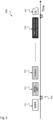
- Beamforming is widely used in Wi-Fi communication systems as a technique to improve performance in MIMO scenarios, e.g. as shown in Fig. 1 where an access point 110 transmits in downlink direction to a plurality of client stations 101, 102, 103, e.g. by using a wide beam 111, and each client station 101, 102, 103 transmits in uplink direction towards the access point 110, e.g. by using a narrow beam 104, 105, 106.
- IEEE 802.11n/ac/ax support feedback of precoding matrices that can be used for beamforming. Many contributions and much research were carried out in order to examine the properties of beamforming and design efficient methods to support it.
- the procedures are optimized mostly for downlink transmission and may be (partially or non-efficiently) reused by the uplink.
- various problems will arise as the uplink transmission is different from the downlink transmission.
- DL beamforming is fully managed by the AP 110 while the precoder can be adjusted according to currently scheduled transmission.
- Different transmission schemes may require different precoders to achieve better performance - SU, MU, MU-MIMO.
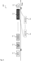
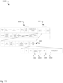
- AP 110 collects the feedback information from different stations 101, 102, 103 and may compute the relevant precoder optimized for specific packet, e.g. as shown in Fig. 2 where after NDPA 201, NDP 202, trigger frame 203 and Multi User Feedback 204 transmission, different precoders may be required for STA1, 101 to achieve better performance: SU Data STA1, 205, MU-MIMO STA1&2, 206, and MU-MIMO STA1&3, 207.
- Nonorthogonal precoder - SVD based precoder may be not optimal if Nss > 1 (same STA may transmit with different Nss in MU and MU-MIMO); Decoder type relaxation - AP may adjust a precoder type for a detector that will be applied, for example to use MMSE instead of ML to detect MU-MIMO; Null Steering - advanced interference mitigation schemes may require different precoder adjusted to current interference spatial properties.
- AP currently access point
- AP cannot update and inform STAs regarding specific precoder that should be applied in the next UL frame.
- a beamformee is a receiver that is capable of obtaining, calculating and returning (i.e. feeding back) beamforming data, e.g. in accordance with a protocol (e.g. a WiFi protocol) and is capable of participating in a sounding procedure.
- a protocol e.g. a WiFi protocol
- WiFi receiver can operate as a beamformee.
- CN 107 241 798 A discloses a kind of indicating means of resource allocation and relevant device.
- US 2018/167177 A1 discloses communication networks and, more particularly, to sounding methods in wireless local area networks based on OFDMA and MU-MIMO.
- US 2017/111924 A1 discloses frame formats for orthogonal frequency division multiple access (OFDMA) and multi-user multiple-input multiple-output (MU-MIMO) uplink feedback transmissions in packet based wireless systems, for example IEEE 802.11.
- OFDMA orthogonal frequency division multiple access
- MU-MIMO multi-user multiple-input multiple-output
- a main idea of the invention is to transmit, by a beamformee device, e.g. a WiFi access point, to one or more beamformer devices, e.g. WiFi client stations, an indication of a precoder for Uplink transmission per Uplink transmission.
- a beamformee device e.g. a WiFi access point
- one or more beamformer devices e.g. WiFi client stations
- an adjustment of the precoder per UL frame is justified and a method that supports it is presented.
- the invention relates to a method for managing beamformed uplink transmissions of one or more beamformer devices, e.g. WiFi client stations, wherein the method is initialized by a beamformee device, e.g. a WiFi access point, the method comprising: transmitting, by a beamformee device, e.g. a WiFi access point, to one or more beamformer devices, e.g. WiFi client stations, an indication of a precoder for Uplink transmission per Uplink transmission.
- a beamformee device e.g. a WiFi access point
- SVD based precoder can be optimally designed even if Nss > 1;
- AP can adjust a precoder type for a detector that will be applied, advanced interference mitigation schemes can be applied which require different precoder adjusted to current interference spatial properties.
- AP can update and inform STAs regarding specific precoder that should be applied in the next UL frame.
- the method comprises transmitting, by the beamformee device, a trigger frame to the one or more beamformer devices, wherein the trigger frame comprises the indication of the precoder.
- the trigger frame comprises an indication of a specific precoder per uplink transmission that is based on previously collected channel state information, wherein the specific precoder is included within the trigger frame.
- This provides the advantage that an optimal precoder can be used for UL transmission when a selection of the precoder is based on channel state information.
- the method comprises: selecting, by the beamformee device, a precoder per beamformer device from a set of precoders produced for different uplink transmissions; and indicating the selected precoder per beamformer device in the trigger frame.
- the method comprises: selecting, by the beamformee device, a precoder per beamformer device for different types of uplink transmissions, wherein the different types of uplink transmissions are from the following: Single-User, SU, Multiple-User, MU, Multiple-User-MIMO, or from further types of uplink transmissions.
- This provides the advantage that the indication of the precoder can be applied in multiple modes of beamformed communications such as SU, MU, MU-MIMO and others.
- the trigger frame comprises a trigger frame indication field that includes the following information per beamformer device scheduled for the next uplink transmission: precoder type indication for indicating which type of precoder to use, and precoder data, e.g. wideband precoder data or codebook based precoder data with Precoding Matrix Indicator, PMI.
- precoder type indication for indicating which type of precoder to use
- precoder data e.g. wideband precoder data or codebook based precoder data with Precoding Matrix Indicator, PMI.
- trigger frame indication field can transport all relevant data required by the beamformer devices from the beamformee device to beamformer devices.
- the precoder type indication indicates one of the following precoder types: first type: no precoder required, second type: last updated precoder to be used, third type: precoder indicated in trigger frame to be used, fourth type: precoder update will follow the trigger frame, by special precoder update frame, or further types of precoders.
- This provides the advantage that the indication of precoder can be flexibly applied in different situations and environments, in particular for saving resources.
- the method comprises: transmitting, by a beamformee device, a channel sounding announcement, e.g. a Null Data Packet Announcement, NDPA, for prompting the beamformer devices initiating a channel sounding procedure, and to receive a corresponding channel sounding frame, e.g. a Null Data Packet, NDP, from the beamformer devices responsive to the channel sounding announcement; transmitting, by the beamformee device, a feedback frame to a respective channel sounding frame, and transmitting, by the beamformee device, two or more different feedback update frames for updating a beamformer device with new precoding information to the same beamformer device based on the same channel sounding frame.
- a channel sounding announcement e.g. a Null Data Packet Announcement, NDPA
- NDP Null Data Packet
- the method comprises: transmitting, by the beamformee device, multiple feedback frames between two NDPA-NDP transmissions.
- WiFi client stations an indication of a precoder for Uplink transmission per Uplink transmission, transmit a trigger frame to the one or more beamformer devices, wherein the trigger frame comprises the indication of the precoder; transmit a channel sounding announcement, for prompting the multiple beamformer devices initiating a channel sounding procedure, and to receive a corresponding channel sounding frame from the beamformer devices responsive to the channel sounding announcement; transmit a feedback frame to a respective channel sounding frame; transmit two or more different feedback update frames for updating a beamformer device with new precoding information to the same beamformer device based on the same channel sounding frame.
- the precoder type indication indicates one of the following precoder types: first type: no precoder required, second type: last updated precoder to be used, third type: precoder indicated in trigger frame to be used, fourth type: precoder update will follow the trigger frame, by special precoder update frame, or further types of precoders.
- the radio device is configured to transmit multiple feedback frames between two NDPA-NDP transmissions.
- the radio device is configured to compute CSI information from the channel sounding procedure and to assign a precoder to a respective client station based on the computed CSI information.
- the feedback update frame comprises one of the following: precoding matrices data based on previously performed channel sounding procedure, e.g. NDPA-NDP procedure, feedback type indication to allow further usage of the same precoder.
- the described devices may include integrated circuits and/or passives and may be manufactured according to various technologies.
- the circuits may be designed as logic integrated circuits, analog integrated circuits, mixed signal integrated circuits, optical circuits, memory circuits and/or integrated passives.
- processors may include processors.
- processor describes any device that can be utilized for processing specific tasks (or blocks or steps).
- a processor can be a single processor or a multi-core processor or can include a set of processors or can include means for processing.
- a processor can process software or firmware or applications etc.
- OFDM is a frequency-division multiplexing scheme used as a digital multi-carrier modulation method.
- a large number of closely spaced orthogonal sub-carrier signals are used to carry data on several parallel data streams or channels.
- Channel equalization is simplified because OFDM may be viewed as using many slowly modulated narrowband signals rather than one rapidly modulated wideband signal.
- the low symbol rate makes the use of a guard interval between symbols affordable, making it possible to eliminate intersymbol interference (ISI) and utilize echoes and time-spreading to achieve a diversity gain, i.e. a signal-to-noise ratio improvement.
- ISI intersymbol interference
- echoes and time-spreading to achieve a diversity gain, i.e. a signal-to-noise ratio improvement.
- the beginning of each symbol is preceded by a guard interval. As long as the echoes fall within this interval, they will not affect the receiver's ability to safely decode the actual data, as data is only interpreted
- the methods and devices described herein may be implemented based on WiFi communication standards according to IEEE 802.11, e.g. IEEE 802.11n/ax/be.
- the 802.11ax standard has two modes of operation: 1) Single User: IN this sequential mode the wireless STAs send an receive data one at a time once they secure access to the medium; 2) Multi-User: This mode allows for simultaneous operation of multiple non-AP STAs.
- the standard divides this mode further into Downlink and Uplink Multi-User.
- the Multi-User mode of operation the standard also specifies two different ways of multiplexing more users within a certain area: Multi-User MIMO and Orthogonal Frequency Division Multiple Access (OFDMA).
- the AP acts as the central controller of all aspects of multi-user operation.
- An 802.11ax AP can also combine MU-MIMO with OFDMA operation.
- the AP applies the channel matrix to the received beams and separates the information that each uplink beam contains.
- the AP may also initiate Uplink multi-user transmissions to receive beamforming feedback information from all participating STAs.
- the devices and systems described herein may include processors or processing devices or processing circuitries, memories and transceivers, i.e. transmitters and/or receivers for computing the beamformed transmissions.
- processors or processing devices or processing circuitries memories and transceivers, i.e. transmitters and/or receivers for computing the beamformed transmissions.
- the term "processor” or “processing device” describes any device that can be utilized for processing specific tasks (or blocks or steps).
- a processor or processing device can be a single processor or a multi-core processor or can include a set of processors or can include means for processing.
- a processor or processing device can process software or firmware or applications etc.
- Fig. 1 shows a schematic diagram of beamforming communication system 100 with an access point 110 and a plurality of client stations 101, 102, 103.
- an access point 110 transmits in downlink direction to a plurality of client stations 101, 102, 103, e.g. by using a wide beam 111, and each client station 101, 102, 103 transmits in uplink direction towards the access point 110, e.g. by using a narrow beam 104, 105, 106.
- the access point 110 may be designed to initiate the client stations 101, 102, 103 to perform a beamforming procedure as described in this disclosure.
- DL beamforming is fully managed by the AP 220, e.g. AP 110 as shown in Fig. 1 while the precoder can be adjusted according to currently scheduled transmission. Different transmission schemes may require different precoders to achieve better performance - SU, MU, MU-MIMO.
- AP 220 collects the feedback information from different stations 210, e.g. stations 101, 102, 103 as shown in Fig. 1 , and may compute the relevant precoder optimized for specific packet.
- SU Data STA1, 205 SU Data STA1, 205
- MU-MIMO STA1&2, 206 MU-MIMO STA1&3, 207.
- Fig. 3 shows a schematic diagram illustrating an exemplary beamforming procedure application 300 in Uplink.
- Fig. 4 shows a schematic diagram illustrating an exemplary Trigger-based Uplink transmission 400.
- the trigger-based Uplink transmission 400 includes a trigger frame 203 and MU Data 401.
- the trigger-based Uplink transmission 400 may be applied in the WiFi standard 802.11ax as a trigger based procedure for UL multiuser transmissions, including MU-MIMO.
- the whole transmission 500 includes an NDPA (Null Data Packet Announcement) frame 201, an MU/SU NDP frame 501 following the NDPA 201 after a short interframe space (SIFS) 506, a feedback frame 502, after some time the trigger frame with precoder indication 504 and after a further SIFS 506 the Uplink data 505.
- NDPA Null Data Packet Announcement
- SIFS short interframe space
- the transmission 500 illustrates the concept of Precoder Update Per UL Frame.
- the main idea is to allow AP 220 to indicate to STAs 210 which precoder should be applied.
- the concept is to add to TF 203 relevant information that can both trigger a beamformed transmission and indicate which precoder should be applied.
- Fig. 6 shows a schematic diagram illustrating an exemplary transmission 600 including a Precoding Indication Field Format 601, 602.
- the transmission 600 corresponds to the transmission 500 described above with respect to Fig. 5 with the difference that the trigger frame with precoder indication 504 comprises a plurality of data 601, 602 providing user information for the respective clients or stations 210.
- Fig. 7 shows a schematic diagram illustrating an exemplary transmission 700 including a Precoder Update Frame 701.
- the transmission 700 includes the trigger frame with precoder indication 504 as described above with respect to Figures 5 and 6 , the Precoder Update Frame 701 and UL data 505 that may be separated by SIFS 506.
- Precoder Type Indication is to indicate the Precoder type in the trigger frame 504.
- Precoder type may imply usage of one of the precoders that was sent previously to STA 210 or may indicate that precoder update is transmitted or that precoder update will follow the TF 504, by Precoder Update Frame 701.
- the following indication is just for example, i.e. any other bit configuration may be used.
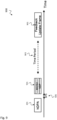
- Fig. 8 shows a schematic diagram illustrating an exemplary transmission 800 including multiple feedback transmission 502 between an NDPA-NDP message 201, 501.
- the whole transmission 800 includes an NDPA (Null Data Packet Announcement) frame 201, an MU/SU NDP frame 501 following the NDPA 201 after a SIFS 506, a feedback frame 502, after any time period 802 further feedback frame 502 and after any further time period 803 further NDPA 201 and further MU/SU NDP 501.
- NDPA Null Data Packet Announcement
- NDPA-NDP procedure implicitly assumes immediate single feedback transmission and applying a precoder in the next frame.
- a new method is introduced, where feedback transmission 502 can be done any time 802 after NDPA-NDP 201, 501 is performed and multiple feedback transmission 502 may be done between two NDPA-NDP transmissions 201, 501. This allows the AP 220 to collect CSI information, and to decide later which precoder should be applied for a specific UL frame.
- Fig. 9 shows a schematic diagram illustrating an exemplary transmission 900 including a Feedback Update Frame 901.
- the whole transmission 900 includes an NDPA frame 201, a MU/SU NDP frame 501 as described above with respect to Fig. 8 and after a time period 903 a feedback update frame 901.
- Precoder Update Frame Format is described in the following: AP 220 may calculate different precoders to apply for different types of UL transmissions (e.g. SU, MU, MU-MIMO with different groups).
- the AP 220 may transmit a feedback update frame 901.
- Feedback update frame 901 may be transmitted in SU or MU format.
- the feedback update frame 901 can include the following: Precoding matrices data based on previously performed NDPA-NDP procedure; and Feedback type indication - to allow further usage of the same precoder.
- the feedback update frame 901 can include further information.
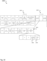
- Fig. 10 shows a schematic diagram illustrating an exemplary implementation of a Trigger Frame Format 1000 according to a first option.
- the Trigger Frame Format 1000 includes common information 1010 and per user information 1020, e.g. for users 1 to M. Each user-specific information 1020 includes trigger-dependent user information 1021 which includes, beside identifications Nc and Nr, codebook information 1022 and feedback type 1023.
- an access point 220 may generate a trigger frame compatible with two types of stations 210, such as EHT STAs and legacy (or high efficiency (HE)) STAs.
- the AP may transmit the trigger frame to a group of STAs, where legacy STAs may process the trigger frame as a legacy trigger frame.
- EHT STAs may process the trigger frame to determine resource unit (RU) allocations for uplink transmissions in a bandwidth greater than a legacy bandwidth.
- An EHT STA may determine the resources in the larger bandwidth based on an EHT RU allocation table, a legacy RU allocation table and an additional bit in the trigger frame, or an ordering of RU allocations in the trigger frame.
- Fig. 11 shows a schematic diagram illustrating an exemplary implementation of a Trigger Frame Format 1100 according to a second option.
- Precoding matrix 1102 is explicitly indicated in the trigger dependent user information 1021 of the EHT trigger frame. One or multiple fields can exist.
- the Trigger Frame Format 1100 includes common information 1010 and per user information 1020, e.g. for users 1 to M.
- Each user-specific information 1020 includes trigger-dependent user information 1021 which includes, beside identifications Nc and Nr, codebook information 1022, feedback type 1023, SNR 1101 and Precoding matrix 1102.
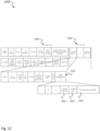
- Fig. 12 shows a schematic diagram illustrating an exemplary implementation of a Trigger Frame Format 1200 according to a third option.
- a new trigger type is used for EHT trigger frame or for a basic trigger type, a reserved bit is used to differentiate HE/EHT basic trigger frame.
- a codebook is predefined. One or multiple fields can exist.
- the Trigger Frame Format 1200 includes common information 1010 and per user information 1020, e.g. for users 1 to M.
- Each user-specific information 1020 includes trigger-dependent user information 1021 which includes, beside identifications Nc and Nr, codebook information 1022, feedback type 1023, and Precoding Matrix Index (PMI) 1201.
- PMI Precoding Matrix Index
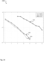
- Fig. 13 shows a performance diagram 1300 illustrating an exemplary single user (SU) performance when beamforming is applied in the Uplink
- Fig. 14 shows a performance diagram 1400 illustrating an exemplary multi user MIMO (MU-MIMO) performance when beamforming is applied in the Uplink.
- SU single user
- MU-MIMO multi user MIMO
- graph 1303 shows narrowband beamforming
- graph 1302 shows wideband beamforming while graph 1301 shows result without beamforming
- graph 1403 shows narrowband beamforming
- graph 1402 shows wideband beamforming while graph 1401 shows result without beamforming.
- Fig. 15 shows a schematic diagram of a method 1500 for managing beamformed uplink transmissions.
- the method 1500 is used for managing beamformed uplink transmissions of one or more beamformer devices 210, e.g. as described above with respect to Figures 2 to 12 , e.g. WiFi client stations 101, 102, 103, e.g. as shown in Fig. 1 .
- the method 1500 is initialized by a beamformee device 220, e.g. a WiFi access point 110.
- the method 1500 comprises: transmitting 1501, by a beamformee device 220, e.g. a WiFi access point 110, to one or more beamformer devices 210, e.g. WiFi client stations 101, 102, 103, an indication of a precoder for Uplink transmission per Uplink transmission 104, 105, 106, e.g. as described above with respect to Figures 4 to 14 .
- the method 1500 comprises: Transmitting 1501, by the beamformee device 220, a trigger frame, e.g. a trigger frame 203, 504 as described above with respect to Figures 4 to 12 , to the one or more beamformer devices, wherein the trigger frame 504 comprises the indication of the precoder.
- a trigger frame e.g. a trigger frame 203, 504 as described above with respect to Figures 4 to 12 .
- the trigger frame 504 comprises an indication of a specific precoder per uplink transmission that is based on previously collected channel state information, wherein the specific precoder is included within the trigger frame 504, e.g. as described above with respect to Figures 4 to 14 .
- the method 1500 comprises: selecting, by the beamformee device 220, a precoder per beamformer device 210 from a set of precoders produced for different uplink transmissions; and indicating the selected precoder per beamformer device 210 in the trigger frame 504, e.g. as described above with respect to Figures 4 to 14 .
- the method 1500 comprises: selecting, by the beamformee device 220, a precoder per beamformer device 210 for different types of uplink transmissions, wherein the different types of uplink transmissions are from the following: Single-User, SU, Multiple-User, MU, Multiple-User-MIMO, or from further types of uplink transmissions, e.g. as described above with respect to Figures 4 to 14 .
- the trigger frame 504 comprises a trigger frame indication field that includes the following information 601, 602 per beamformer device 210 scheduled for the next uplink transmission: precoder type indication for indicating which type of precoder to use, and precoder data for indicating precoding data, e.g. wideband precoder or codebook based precoder with Precoding Matrix Indicator, PMI, e.g. as described above with respect to Figure 6 .
- precoder type indication for indicating which type of precoder to use
- precoder data for indicating precoding data, e.g. wideband precoder or codebook based precoder with Precoding Matrix Indicator, PMI, e.g. as described above with respect to Figure 6 .
- the precoder type indication indicates one of the following precoder types: first type: no precoder required, second type: last updated precoder to be used, third type: precoder indicated in trigger frame to be used, fourth type: precoder update will follow the trigger frame, by special precoder update frame, or further types of precoders, e.g. as described above with respect to Figure 7 .
- the method 1500 comprises: transmitting, by a beamformee device 220, a channel sounding announcement, e.g. a Null Data Packet Announcement, NDPA 201, for prompting the beamformer devices 210 initiating a channel sounding procedure, and to receive a corresponding channel sounding frame, e.g.
- a channel sounding announcement e.g. a Null Data Packet Announcement, NDPA 201
- a Null Data Packet, NDP, 501 from the beamformer devices 210 responsive to the channel sounding announcement 201; transmitting, by the beamformee device 220, a feedback frame 502 to a respective channel sounding frame 501, and transmitting, by the beamformee device 220, two or more different feedback update frames 901 for updating a beamformer device 210 with new precoding information to the same beamformer device 210 based on the same channel sounding frame 501.
- the method 1500 comprises: transmitting, by the beamformee device 220, multiple feedback frames 502 between two NDPA-NDP transmissions, e.g. as described above with respect to Figure 8 .
- the method 1500 comprises: computing, by the beamformee device, channel state information (CSI) from the channel sounding procedure and; assigning a precoder to a respective beamformer device based on the computed CSI information, e.g. as described above with respect to Figures 4 to 12 .
- CSI channel state information
- the feedback update frame comprises one of the following: precoding matrices data based on previously performed channel sounding procedure, e.g. NDPA-NDP procedure, feedback type indication to allow further usage of the same precoder, e.g. as described above with respect to Figure 9 .
- the trigger frame comprises common information 1010 and per user information 1020, e.g. as defined by 802.11ax WiFi communications standard, wherein the per user information 1020 comprises trigger dependent user information 1021 which indicates a precoder for Uplink beamforming, e.g. as described above with respect to Figures 10 to 12 .
- the trigger dependent user information 1021 indicates to use a last updated precoding matrix by not explicitly indicating a precoding matrix, e.g. as described above with respect to Figure 10 .
- the trigger dependent user information 1021 comprises a precoding matrix 1102 to use, e.g. as described above with respect to Figure 11 .
- the trigger dependent user information 1021 comprises a Precoding Matrix Index (PMI) 1201, to indicate a precoding matrix from a predefined codebook, e.g. as described above with respect to Figure 12 .
- PMI Precoding Matrix Index
- the method 1500 may be applied in a beamformee device, e.g. an access point 110 as shown in Figure 1 .
- Such a beamformee device 110 can be used for initiating beamformed uplink transmissions of one or more beamformer devices, e.g. WiFi client stations 101, 102, 103, e.g. as shown in Fig. 1 , wherein the beamformee device 110 is configured to: transmit to one or more beamformer devices, e.g. WiFi client stations 101, 102, 103, an indication of a precoder for Uplink transmission per Uplink transmission, e.g. as described above with respect to Figures 4 to 12 .
- the present disclosure also supports a computer program product including computer executable code or computer executable instructions that, when executed, causes at least one computer to execute the performing and computing steps described herein, in particular the steps of the method 1500 described above.
- a computer program product may include a readable non-transitory storage medium storing program code thereon for use by a computer.
- the program code may perform the processing and computing steps described herein, in particular the method 1500 described above.
Landscapes
- Engineering & Computer Science (AREA)
- Computer Networks & Wireless Communication (AREA)
- Signal Processing (AREA)
- Physics & Mathematics (AREA)
- Mathematical Physics (AREA)
- Mobile Radio Communication Systems (AREA)
- Radio Transmission System (AREA)
Claims (13)
- Verfahren (1500) zum Verwalten von strahlgeformten Uplink-Übertragungen von einer oder mehreren Strahlformervorrichtungen (210), wobei das Verfahren (1500) durch eine strahlgeformte Vorrichtung (220) eingeleitet wird, wobei das Verfahren umfasst:Übertragen (1501), durch eine strahlgeformte Vorrichtung (220), an eine oder mehrere Strahlformervorrichtungen (210), einer Anzeige eines Vorcodierers für die Uplink-Übertragung pro Uplink-Übertragung (104, 105, 106);Übertragen (1501), durch die strahlgeformte Vorrichtung (220), eines Auslöserahmens (504) an die eine oder die mehreren Strahlformervorrichtungen, wobei der Auslöserahmen (504) die Anzeige des Vorcodierers umfasst;vor dem Übertragen des Auslöserahmens, Übertragen, durch die strahlgeformte Vorrichtung (220), einer Channel-Sounding-Ankündigung zum Auffordern der Strahlformervorrichtungen (210), eine Channel-Sounding-Prozedur einzuleiten, und um als Reaktion auf die Channel-Sounding-Ankündigung (201) einen entsprechenden Channel-Sounding-Rahmen von den Strahlformervorrichtungen (210) zu empfangen;Übertragen, durch die strahlgeformte Vorrichtung (220), eines Rückkopplungsrahmens (502) an einen entsprechenden Channel-Sounding-Rahmen (501), undÜbertragen, durch die strahlgeformte Vorrichtung (220), von zwei oder mehr unterschiedlichen Rückkopplungsaktualisierungsrahmen (901) zum Aktualisieren einer Strahlformervorrichtung (210) mit neuen Vorcodierungsinformationen an dieselbe Strahlformervorrichtung (210) basierend auf demselben Channel-Sounding-Rahmen (501).
- Verfahren (1500) nach Anspruch 1,
wobei der Auslöserahmen (504) eine Anzeige eines spezifischen Vorcodierers pro Uplink-Übertragung, die auf zuvor erfassten Kanalzustandsinformationen basiert, umfasst, wobei der spezifische Vorcodierer innerhalb des Auslöserahmens (504) enthalten ist. - Verfahren (1500) nach Anspruch 1 oder 2, das umfasst:
Auswählen, durch die strahlgeformte Vorrichtung (220), eines Vorcodierers pro Strahlformervorrichtung (210) aus einem Satz von Vorcodierern, die für unterschiedliche Uplink-Übertragungen erzeugt werden; und Anzeigen des ausgewählten Vorcodierers pro Strahlformervorrichtung (210) in dem Auslöserahmen (504). - Verfahren (1500) nach einem der Ansprüche 1 bis 3, das umfasst:
Auswählen, durch die strahlgeformte Vorrichtung (220), eines Vorcodierers pro Strahlformervorrichtung (210) für unterschiedliche Arten von Uplink-Übertragungen, wobei die unterschiedlichen Arten von Uplink-Übertragungen aus den Folgenden sind:Einzelbenutzer, SU,Mehrfachbenutzer, MU, oderMehrfachbenutzer-MIMO. - Verfahren (1500) nach einem der Ansprüche 1 bis 4,
wobei der Auslöserahmen (504) ein Auslöserahmenanzeigefeld umfasst, das die folgenden Informationen (601, 602) pro Strahlformervorrichtung (210), die für die nächste Uplink-Übertragung geplant ist, enthält:eine Vorcodiererartanzeige zum Anzeigen, welche Art von Vorcodierer genutzt werden soll, undVorcodiererdaten. - Verfahren (1500) nach Anspruch 5,
wobei die Vorcodiererartanzeige eine der folgenden Vorcodiererarten anzeigt:erste Art: kein Vorcodierer erforderlich,zweite Art: der zuletzt aktualisierte Vorcodierer soll genutzt werden,dritte Art: Vorcodierer, der in dem Auslöserahmen angezeigt wird, soll genutzt werden, odervierte Art: Vorcodiereraktualisierung folgt auf den Auslöserahmen, durch einen speziellen Vorcodiereraktualisierungsrahmen. - Verfahren (1500) nach einem der vorstehenden Ansprüche, das umfasst:
Übertragen, durch die strahlgeformte Vorrichtung (220), einer Mehrzahl von Rückkopplungsrahmen (502) zwischen zwei Channel-Sounding-Ankündigung - Channel-Sounding-Rahmen-Übertragungen. - Verfahren (1500) nach einem der vorstehenden Ansprüche, das umfasst:
Berechnen, durch die strahlgeformte Vorrichtung, von CSI-Informationen aus der Channel-Sounding-Prozedur, und; Zuweisen eines Vorcodierers zu einer jeweiligen Strahlformervorrichtung basierend auf den berechneten CSI-Informationen. - Verfahren (1500) nach einem der vorstehenden Ansprüche,
wobei der Rückkopplungsaktualisierungsrahmen eines der Folgenden umfasst:Vorcodieren von Matrizendaten basierend auf der zuvor durchgeführten Channel-Sounding-Prozedur,Rückkopplungsartanzeige, um eine weitere Nutzung desselben Vorcodierers zu ermöglichen. - Verfahren (1500) nach einem der vorstehenden Ansprüche,wobei der Auslöserahmen allgemeine Informationen und Informationen pro Benutzer umfasst,wobei die Informationen pro Benutzer auslöserabhängige Benutzerinformationen, die einen Vorcodierer für ein Uplink-Strahlformen anzeigen, umfassen.
- Verfahren (1500) nach Anspruch 10,
wobei die auslöserabhängigen Benutzerinformationen anzeigen, dass eine zuletzt aktualisierte Vorcodierungsmatrix durch nicht explizites Anzeigen einer Vorcodierungsmatrix genutzt werden soll. - Verfahren (1500) nach Anspruch 10,wobei die auslöserabhängigen Benutzerinformationen eine Vorcodierungsmatrix, die genutzt werden soll, umfassen; oderwobei die auslöserabhängigen Benutzerinformationen einen Vorcodierungsmatrixindex, PMI, umfassen, um eine Vorcodierungsmatrix aus einem zuvor definierten Codebuch anzuzeigen.
- Strahlgeformte Vorrichtung (110) zum Einleiten von strahlgeformten Uplink-Übertragungen von einer oder mehreren Strahlformervorrichtungen, wobei die strahlgeformte Vorrichtung konfiguriert ist zum:Übertragen an eine oder mehrere Strahlformervorrichtungen einer Anzeige eines Vorcodierers für die Uplink-Übertragung pro Uplink-Übertragung;Übertragen eines Auslöserahmens an die eine oder die mehreren Strahlformervorrichtungen, wobei der Auslöserahmen die Anzeige des Vorcodierers umfasst;vor dem Übertragen des Auslöserahmens, Übertragen einer Channel-Sounding-Ankündigung zum Auffordern der Mehrzahl von Strahlformervorrichtungen, eine Channel-Sounding-Prozedur einzuleiten, und um als Reaktion auf die Channel-Sounding-Ankündigung einen entsprechenden Channel-Sounding-Rahmen von den Strahlformervorrichtungen zu empfangen;Übertragen eines Rückkopplungsrahmens an einen jeweiligen Channel-Sounding-Rahmen;Übertragen von zwei oder mehr unterschiedlichen Rückkopplungsaktualisierungsrahmen zum Aktualisieren einer Strahlformervorrichtung mit neuen Vorcodierungsinformationen an dieselbe Strahlformervorrichtung basierend auf demselben Channel-Sounding-Rahmen.
Applications Claiming Priority (1)
| Application Number | Priority Date | Filing Date | Title |
|---|---|---|---|
| PCT/EP2019/079359 WO2021083476A1 (en) | 2019-10-28 | 2019-10-28 | Techniques for managing beamformed uplink transmissions of beamformer devices |
Publications (2)
| Publication Number | Publication Date |
|---|---|
| EP4038757A1 EP4038757A1 (de) | 2022-08-10 |
| EP4038757B1 true EP4038757B1 (de) | 2025-03-26 |
Family
ID=68382455
Family Applications (1)
| Application Number | Title | Priority Date | Filing Date |
|---|---|---|---|
| EP19795001.7A Active EP4038757B1 (de) | 2019-10-28 | 2019-10-28 | Techniken zum verwalten von strahlgeformten uplink-übertragungen von strahlformern |
Country Status (3)
| Country | Link |
|---|---|
| EP (1) | EP4038757B1 (de) |
| CN (1) | CN114514705B (de) |
| WO (1) | WO2021083476A1 (de) |
Families Citing this family (4)
| Publication number | Priority date | Publication date | Assignee | Title |
|---|---|---|---|---|
| CN120263238A (zh) * | 2023-12-26 | 2025-07-04 | 深圳市中兴微电子技术有限公司 | 帧处理方法、网络设备和存储介质 |
| WO2025207891A1 (en) * | 2024-03-29 | 2025-10-02 | Ofinno, Llc | Reusable beamforming information at a station |
| WO2025213309A1 (en) * | 2024-04-07 | 2025-10-16 | Huawei Technologies Co., Ltd. | Devices and methods for reliable sounding in a wireless network |
| WO2025217356A1 (en) * | 2024-04-11 | 2025-10-16 | Ofinno, Llc | Beamforming information persistence at a station |
Family Cites Families (6)
| Publication number | Priority date | Publication date | Assignee | Title |
|---|---|---|---|---|
| US10158413B2 (en) * | 2015-05-08 | 2018-12-18 | Newracom, Inc. | Uplink sounding for WLAN system |
| JP7186394B2 (ja) * | 2015-08-31 | 2022-12-09 | パナソニックIpマネジメント株式会社 | 通信装置及び方法 |
| US10143003B2 (en) * | 2015-10-15 | 2018-11-27 | Samsung Electronics Co., Ltd. | Methods and apparatus for beamforming feedback in wireless systems |
| US10171265B2 (en) * | 2015-11-10 | 2019-01-01 | Qualcomm Incorporated | Uplink channel information |
| CN107241798A (zh) * | 2016-03-28 | 2017-10-10 | 华为技术有限公司 | 一种资源分配的指示方法及相关设备 |
| CA3035000C (en) * | 2016-09-26 | 2022-06-14 | Lg Electronics Inc. | Uplink transmission/reception method in wireless communication system and device therefor |
-
2019
- 2019-10-28 EP EP19795001.7A patent/EP4038757B1/de active Active
- 2019-10-28 CN CN201980101292.9A patent/CN114514705B/zh active Active
- 2019-10-28 WO PCT/EP2019/079359 patent/WO2021083476A1/en not_active Ceased
Also Published As
| Publication number | Publication date |
|---|---|
| CN114514705A (zh) | 2022-05-17 |
| WO2021083476A1 (en) | 2021-05-06 |
| EP4038757A1 (de) | 2022-08-10 |
| CN114514705B (zh) | 2024-10-18 |
Similar Documents
| Publication | Publication Date | Title |
|---|---|---|
| CN110574314B (zh) | 在无线通信系统中报告信道状态信息的方法及其设备 | |
| US10305660B2 (en) | Method and apparatus for allocating wireless resources | |
| JP5837068B2 (ja) | 無線ネットワークでアップリンクサウンディングレファレンス信号の伝送のための方法及び装置 | |
| AU2011302802B2 (en) | System and method for PUCCH subband feedback signaling in a wireless network | |
| US9258070B2 (en) | Simultaneous feedback signaling for dynamic bandwidth selection | |
| KR101763290B1 (ko) | 3gpp 무선 네트워크에서 pucch 피드백을 위한 시스템 및 방법 | |
| US9780926B2 (en) | Burst OFDMA supporting MU-MIMO | |
| US9814003B2 (en) | Transmission of information in a wireless communication system | |
| CN113574815A (zh) | 用于多传输点(trp)传输的低开销信道状态信息(csi)反馈 | |
| US8009580B2 (en) | Signaling and training for antenna selection in OFDMA networks | |
| CN110226304B (zh) | 下一代无线通信系统中执行子带单元下行链路调度的方法及其装置 | |
| CN110771073A (zh) | 用于在无线通信系统中报告信道状态信息的方法及其设备 | |
| KR20170091664A (ko) | 부분 프리코딩 csi-rs 및 csi 피드백을 위한 다운링크 시그널링 방법 및 장치 | |
| EP4038757B1 (de) | Techniken zum verwalten von strahlgeformten uplink-übertragungen von strahlformern | |
| US11177982B2 (en) | System and method for providing explicit feedback in the uplink | |
| WO2011058716A1 (en) | Communication apparatus, communication method, computer program and communication system | |
| US20230008939A1 (en) | Method for unified uplink and downlink beam indication | |
| EP4113885B1 (de) | Kanalsondierungsvorrichtung und -verfahren | |
| US8363587B2 (en) | Signaling methods for MMSE precoding with eigenmode selection | |
| US10756794B2 (en) | Method for reporting channel quality information in distributed antenna communication system and apparatus therefor | |
| US20240030974A1 (en) | Apparatus and method of uplink beamforming in wireless local area network system | |
| CN119968782A (zh) | 用于在无线通信系统中发送或接收探测参考信号的方法及装置 | |
| KR20250085530A (ko) | 채널 사운딩을 위한 장치 및 방법 |
Legal Events
| Date | Code | Title | Description |
|---|---|---|---|
| STAA | Information on the status of an ep patent application or granted ep patent |
Free format text: STATUS: UNKNOWN |
|
| STAA | Information on the status of an ep patent application or granted ep patent |
Free format text: STATUS: THE INTERNATIONAL PUBLICATION HAS BEEN MADE |
|
| PUAI | Public reference made under article 153(3) epc to a published international application that has entered the european phase |
Free format text: ORIGINAL CODE: 0009012 |
|
| STAA | Information on the status of an ep patent application or granted ep patent |
Free format text: STATUS: REQUEST FOR EXAMINATION WAS MADE |
|
| 17P | Request for examination filed |
Effective date: 20220506 |
|
| AK | Designated contracting states |
Kind code of ref document: A1 Designated state(s): AL AT BE BG CH CY CZ DE DK EE ES FI FR GB GR HR HU IE IS IT LI LT LU LV MC MK MT NL NO PL PT RO RS SE SI SK SM TR |
|
| DAV | Request for validation of the european patent (deleted) | ||
| DAX | Request for extension of the european patent (deleted) | ||
| GRAP | Despatch of communication of intention to grant a patent |
Free format text: ORIGINAL CODE: EPIDOSNIGR1 |
|
| STAA | Information on the status of an ep patent application or granted ep patent |
Free format text: STATUS: GRANT OF PATENT IS INTENDED |
|
| INTG | Intention to grant announced |
Effective date: 20241121 |
|
| GRAS | Grant fee paid |
Free format text: ORIGINAL CODE: EPIDOSNIGR3 |
|
| GRAA | (expected) grant |
Free format text: ORIGINAL CODE: 0009210 |
|
| STAA | Information on the status of an ep patent application or granted ep patent |
Free format text: STATUS: THE PATENT HAS BEEN GRANTED |
|
| AK | Designated contracting states |
Kind code of ref document: B1 Designated state(s): AL AT BE BG CH CY CZ DE DK EE ES FI FR GB GR HR HU IE IS IT LI LT LU LV MC MK MT NL NO PL PT RO RS SE SI SK SM TR |
|
| REG | Reference to a national code |
Ref country code: GB Ref legal event code: FG4D |
|
| REG | Reference to a national code |
Ref country code: CH Ref legal event code: EP |
|
| REG | Reference to a national code |
Ref country code: DE Ref legal event code: R096 Ref document number: 602019067820 Country of ref document: DE |
|
| REG | Reference to a national code |
Ref country code: IE Ref legal event code: FG4D |
|
| PG25 | Lapsed in a contracting state [announced via postgrant information from national office to epo] |
Ref country code: RS Free format text: LAPSE BECAUSE OF FAILURE TO SUBMIT A TRANSLATION OF THE DESCRIPTION OR TO PAY THE FEE WITHIN THE PRESCRIBED TIME-LIMIT Effective date: 20250626 |
|
| PG25 | Lapsed in a contracting state [announced via postgrant information from national office to epo] |
Ref country code: FI Free format text: LAPSE BECAUSE OF FAILURE TO SUBMIT A TRANSLATION OF THE DESCRIPTION OR TO PAY THE FEE WITHIN THE PRESCRIBED TIME-LIMIT Effective date: 20250326 |
|
| REG | Reference to a national code |
Ref country code: LT Ref legal event code: MG9D |
|
| PG25 | Lapsed in a contracting state [announced via postgrant information from national office to epo] |
Ref country code: NO Free format text: LAPSE BECAUSE OF FAILURE TO SUBMIT A TRANSLATION OF THE DESCRIPTION OR TO PAY THE FEE WITHIN THE PRESCRIBED TIME-LIMIT Effective date: 20250626 |
|
| PG25 | Lapsed in a contracting state [announced via postgrant information from national office to epo] |
Ref country code: HR Free format text: LAPSE BECAUSE OF FAILURE TO SUBMIT A TRANSLATION OF THE DESCRIPTION OR TO PAY THE FEE WITHIN THE PRESCRIBED TIME-LIMIT Effective date: 20250326 |
|
| PG25 | Lapsed in a contracting state [announced via postgrant information from national office to epo] |
Ref country code: LV Free format text: LAPSE BECAUSE OF FAILURE TO SUBMIT A TRANSLATION OF THE DESCRIPTION OR TO PAY THE FEE WITHIN THE PRESCRIBED TIME-LIMIT Effective date: 20250326 |
|
| PG25 | Lapsed in a contracting state [announced via postgrant information from national office to epo] |
Ref country code: GR Free format text: LAPSE BECAUSE OF FAILURE TO SUBMIT A TRANSLATION OF THE DESCRIPTION OR TO PAY THE FEE WITHIN THE PRESCRIBED TIME-LIMIT Effective date: 20250627 Ref country code: BG Free format text: LAPSE BECAUSE OF FAILURE TO SUBMIT A TRANSLATION OF THE DESCRIPTION OR TO PAY THE FEE WITHIN THE PRESCRIBED TIME-LIMIT Effective date: 20250326 |
|
| REG | Reference to a national code |
Ref country code: NL Ref legal event code: MP Effective date: 20250326 |
|
| PG25 | Lapsed in a contracting state [announced via postgrant information from national office to epo] |
Ref country code: NL Free format text: LAPSE BECAUSE OF FAILURE TO SUBMIT A TRANSLATION OF THE DESCRIPTION OR TO PAY THE FEE WITHIN THE PRESCRIBED TIME-LIMIT Effective date: 20250326 |
|
| PG25 | Lapsed in a contracting state [announced via postgrant information from national office to epo] |
Ref country code: SE Free format text: LAPSE BECAUSE OF FAILURE TO SUBMIT A TRANSLATION OF THE DESCRIPTION OR TO PAY THE FEE WITHIN THE PRESCRIBED TIME-LIMIT Effective date: 20250326 |
|
| REG | Reference to a national code |
Ref country code: AT Ref legal event code: MK05 Ref document number: 1780002 Country of ref document: AT Kind code of ref document: T Effective date: 20250326 |
|
| PG25 | Lapsed in a contracting state [announced via postgrant information from national office to epo] |
Ref country code: SM Free format text: LAPSE BECAUSE OF FAILURE TO SUBMIT A TRANSLATION OF THE DESCRIPTION OR TO PAY THE FEE WITHIN THE PRESCRIBED TIME-LIMIT Effective date: 20250326 |
|
| PG25 | Lapsed in a contracting state [announced via postgrant information from national office to epo] |
Ref country code: PT Free format text: LAPSE BECAUSE OF FAILURE TO SUBMIT A TRANSLATION OF THE DESCRIPTION OR TO PAY THE FEE WITHIN THE PRESCRIBED TIME-LIMIT Effective date: 20250728 Ref country code: ES Free format text: LAPSE BECAUSE OF FAILURE TO SUBMIT A TRANSLATION OF THE DESCRIPTION OR TO PAY THE FEE WITHIN THE PRESCRIBED TIME-LIMIT Effective date: 20250326 |
|
| PG25 | Lapsed in a contracting state [announced via postgrant information from national office to epo] |
Ref country code: PL Free format text: LAPSE BECAUSE OF FAILURE TO SUBMIT A TRANSLATION OF THE DESCRIPTION OR TO PAY THE FEE WITHIN THE PRESCRIBED TIME-LIMIT Effective date: 20250326 Ref country code: IT Free format text: LAPSE BECAUSE OF FAILURE TO SUBMIT A TRANSLATION OF THE DESCRIPTION OR TO PAY THE FEE WITHIN THE PRESCRIBED TIME-LIMIT Effective date: 20250326 |
|
| PGFP | Annual fee paid to national office [announced via postgrant information from national office to epo] |
Ref country code: GB Payment date: 20250904 Year of fee payment: 7 |
|
| PG25 | Lapsed in a contracting state [announced via postgrant information from national office to epo] |
Ref country code: AT Free format text: LAPSE BECAUSE OF FAILURE TO SUBMIT A TRANSLATION OF THE DESCRIPTION OR TO PAY THE FEE WITHIN THE PRESCRIBED TIME-LIMIT Effective date: 20250326 |
|
| PGFP | Annual fee paid to national office [announced via postgrant information from national office to epo] |
Ref country code: FR Payment date: 20250908 Year of fee payment: 7 |
|
| PG25 | Lapsed in a contracting state [announced via postgrant information from national office to epo] |
Ref country code: EE Free format text: LAPSE BECAUSE OF FAILURE TO SUBMIT A TRANSLATION OF THE DESCRIPTION OR TO PAY THE FEE WITHIN THE PRESCRIBED TIME-LIMIT Effective date: 20250326 |
|
| PG25 | Lapsed in a contracting state [announced via postgrant information from national office to epo] |
Ref country code: RO Free format text: LAPSE BECAUSE OF FAILURE TO SUBMIT A TRANSLATION OF THE DESCRIPTION OR TO PAY THE FEE WITHIN THE PRESCRIBED TIME-LIMIT Effective date: 20250326 |
|
| PG25 | Lapsed in a contracting state [announced via postgrant information from national office to epo] |
Ref country code: SK Free format text: LAPSE BECAUSE OF FAILURE TO SUBMIT A TRANSLATION OF THE DESCRIPTION OR TO PAY THE FEE WITHIN THE PRESCRIBED TIME-LIMIT Effective date: 20250326 |
|
| PG25 | Lapsed in a contracting state [announced via postgrant information from national office to epo] |
Ref country code: IS Free format text: LAPSE BECAUSE OF FAILURE TO SUBMIT A TRANSLATION OF THE DESCRIPTION OR TO PAY THE FEE WITHIN THE PRESCRIBED TIME-LIMIT Effective date: 20250726 |
|
| REG | Reference to a national code |
Ref country code: DE Ref legal event code: R097 Ref document number: 602019067820 Country of ref document: DE |
|
| PGFP | Annual fee paid to national office [announced via postgrant information from national office to epo] |
Ref country code: DE Payment date: 20250902 Year of fee payment: 7 |
|
| PG25 | Lapsed in a contracting state [announced via postgrant information from national office to epo] |
Ref country code: DK Free format text: LAPSE BECAUSE OF FAILURE TO SUBMIT A TRANSLATION OF THE DESCRIPTION OR TO PAY THE FEE WITHIN THE PRESCRIBED TIME-LIMIT Effective date: 20250326 |
|
| PG25 | Lapsed in a contracting state [announced via postgrant information from national office to epo] |
Ref country code: CZ Free format text: LAPSE BECAUSE OF FAILURE TO SUBMIT A TRANSLATION OF THE DESCRIPTION OR TO PAY THE FEE WITHIN THE PRESCRIBED TIME-LIMIT Effective date: 20250326 |
|
| PLBE | No opposition filed within time limit |
Free format text: ORIGINAL CODE: 0009261 |
|
| STAA | Information on the status of an ep patent application or granted ep patent |
Free format text: STATUS: NO OPPOSITION FILED WITHIN TIME LIMIT |
|
| REG | Reference to a national code |
Ref country code: CH Ref legal event code: L10 Free format text: ST27 STATUS EVENT CODE: U-0-0-L10-L00 (AS PROVIDED BY THE NATIONAL OFFICE) Effective date: 20260211 |
|
| 26N | No opposition filed |
Effective date: 20260105 |