EP4038464B1 - Kontinuierliche verwendung der sollgeschwindigkeit anstelle der gemessenen fluggeschwindigkeit für flugsteuerungsentscheidungen - Google Patents
Kontinuierliche verwendung der sollgeschwindigkeit anstelle der gemessenen fluggeschwindigkeit für flugsteuerungsentscheidungen Download PDFInfo
- Publication number
- EP4038464B1 EP4038464B1 EP20873742.9A EP20873742A EP4038464B1 EP 4038464 B1 EP4038464 B1 EP 4038464B1 EP 20873742 A EP20873742 A EP 20873742A EP 4038464 B1 EP4038464 B1 EP 4038464B1
- Authority
- EP
- European Patent Office
- Prior art keywords
- uav
- commanded
- speed
- airspeed
- velocity
- Prior art date
- Legal status (The legal status is an assumption and is not a legal conclusion. Google has not performed a legal analysis and makes no representation as to the accuracy of the status listed.)
- Active
Links
Images


Classifications
-
- G—PHYSICS
- G05—CONTROLLING; REGULATING
- G05D—SYSTEMS FOR CONTROLLING OR REGULATING NON-ELECTRIC VARIABLES
- G05D1/00—Control of position, course, altitude or attitude of land, water, air or space vehicles, e.g. using automatic pilots
- G05D1/02—Control of position or course in two dimensions
- G05D1/0202—Control of position or course in two dimensions specially adapted to aircraft
- G05D1/0204—Control of position or course in two dimensions specially adapted to aircraft to counteract a sudden perturbation, e.g. cross-wind, gust
-
- G—PHYSICS
- G05—CONTROLLING; REGULATING
- G05D—SYSTEMS FOR CONTROLLING OR REGULATING NON-ELECTRIC VARIABLES
- G05D1/00—Control of position, course, altitude or attitude of land, water, air or space vehicles, e.g. using automatic pilots
- G05D1/10—Simultaneous control of position or course in three dimensions
- G05D1/101—Simultaneous control of position or course in three dimensions specially adapted for aircraft
- G05D1/106—Change initiated in response to external conditions, e.g. avoidance of elevated terrain or of no-fly zones
-
- B—PERFORMING OPERATIONS; TRANSPORTING
- B64—AIRCRAFT; AVIATION; COSMONAUTICS
- B64C—AEROPLANES; HELICOPTERS
- B64C29/00—Aircraft capable of landing or taking-off vertically, e.g. vertical take-off and landing [VTOL] aircraft
-
- B—PERFORMING OPERATIONS; TRANSPORTING
- B64—AIRCRAFT; AVIATION; COSMONAUTICS
- B64U—UNMANNED AERIAL VEHICLES [UAV]; EQUIPMENT THEREFOR
- B64U10/00—Type of UAV
- B64U10/20—Vertical take-off and landing [VTOL] aircraft
-
- B—PERFORMING OPERATIONS; TRANSPORTING
- B64—AIRCRAFT; AVIATION; COSMONAUTICS
- B64U—UNMANNED AERIAL VEHICLES [UAV]; EQUIPMENT THEREFOR
- B64U20/00—Constructional aspects of UAVs
- B64U20/80—Arrangement of on-board electronics, e.g. avionics systems or wiring
-
- B—PERFORMING OPERATIONS; TRANSPORTING
- B64—AIRCRAFT; AVIATION; COSMONAUTICS
- B64U—UNMANNED AERIAL VEHICLES [UAV]; EQUIPMENT THEREFOR
- B64U30/00—Means for producing lift; Empennages; Arrangements thereof
- B64U30/10—Wings
-
- B—PERFORMING OPERATIONS; TRANSPORTING
- B64—AIRCRAFT; AVIATION; COSMONAUTICS
- B64U—UNMANNED AERIAL VEHICLES [UAV]; EQUIPMENT THEREFOR
- B64U50/00—Propulsion; Power supply
- B64U50/10—Propulsion
- B64U50/19—Propulsion using electrically powered motors
-
- B—PERFORMING OPERATIONS; TRANSPORTING
- B64—AIRCRAFT; AVIATION; COSMONAUTICS
- B64U—UNMANNED AERIAL VEHICLES [UAV]; EQUIPMENT THEREFOR
- B64U50/00—Propulsion; Power supply
- B64U50/30—Supply or distribution of electrical power
-
- G—PHYSICS
- G05—CONTROLLING; REGULATING
- G05D—SYSTEMS FOR CONTROLLING OR REGULATING NON-ELECTRIC VARIABLES
- G05D1/00—Control of position, course, altitude or attitude of land, water, air or space vehicles, e.g. using automatic pilots
- G05D1/08—Control of attitude, i.e. control of roll, pitch, or yaw
- G05D1/0808—Control of attitude, i.e. control of roll, pitch, or yaw specially adapted for aircraft
- G05D1/0816—Control of attitude, i.e. control of roll, pitch, or yaw specially adapted for aircraft to ensure stability
- G05D1/0833—Control of attitude, i.e. control of roll, pitch, or yaw specially adapted for aircraft to ensure stability using limited authority control
-
- B—PERFORMING OPERATIONS; TRANSPORTING
- B64—AIRCRAFT; AVIATION; COSMONAUTICS
- B64U—UNMANNED AERIAL VEHICLES [UAV]; EQUIPMENT THEREFOR
- B64U2201/00—UAVs characterised by their flight controls
- B64U2201/10—UAVs characterised by their flight controls autonomous, i.e. by navigating independently from ground or air stations, e.g. by using inertial navigation systems [INS]
-
- B—PERFORMING OPERATIONS; TRANSPORTING
- B64—AIRCRAFT; AVIATION; COSMONAUTICS
- B64U—UNMANNED AERIAL VEHICLES [UAV]; EQUIPMENT THEREFOR
- B64U2201/00—UAVs characterised by their flight controls
- B64U2201/20—Remote controls
-
- B—PERFORMING OPERATIONS; TRANSPORTING
- B64—AIRCRAFT; AVIATION; COSMONAUTICS
- B64U—UNMANNED AERIAL VEHICLES [UAV]; EQUIPMENT THEREFOR
- B64U50/00—Propulsion; Power supply
- B64U50/10—Propulsion
- B64U50/13—Propulsion using external fans or propellers
- B64U50/14—Propulsion using external fans or propellers ducted or shrouded
Definitions
- This disclosure relates generally to aerial vehicles, and in particular but not exclusively, relates to control systems for unmanned aerial vehicles (UAVs).
- UAVs unmanned aerial vehicles
- An unmanned vehicle which may also be referred to as an autonomous vehicle, is a vehicle capable of travel without a physically-present human operator.
- An unmanned vehicle may operate in a remote-control mode, in an autonomous mode, or in a partially autonomous mode.
- an unmanned vehicle When an unmanned vehicle operates in a remote-control mode, a pilot or driver that is at a remote location can control the unmanned vehicle via commands that are sent to the unmanned vehicle via a wireless link.
- the unmanned vehicle When the unmanned vehicle operates in autonomous mode, the unmanned vehicle typically moves based on pre-programmed navigation waypoints, dynamic automation systems, or a combination of these. Further, some unmanned vehicles can operate in both a remote-control mode and an autonomous mode, and in some instances may do so simultaneously. For instance, a remote pilot or driver may wish to leave navigation to an autonomous system while manually performing another task, such as operating a mechanical system for picking up objects, as an example.
- Unmanned aerial vehicles UAVs
- UAVs Unmanned aerial vehicles
- UAVs Unmanned aerial vehicles
- Embodiments of a system, apparatus, and method of operation for contingent use of a commanded speed in lieu of a sensed airspeed to inform flight control decisions are described herein.
- numerous specific details are set forth to provide a thorough understanding of the embodiments.
- One skilled in the relevant art will recognize, however, that the techniques described herein can be practiced without one or more of the specific details, or with other methods, components, materials, etc.
- well-known structures, materials, or operations are not shown or described in detail to avoid obscuring certain aspects.
- unmanned aerial vehicles For aerial vehicles, such as unmanned aerial vehicles (UAVs), it is conventional to use airspeed, as measured from an onboard sensor (e.g., pitot probe), to inform flight control decisions. These decisions may include scheduling gains via the application of thrust with one or more propulsion units or allocating control effort applied via control surfaces (e.g., rudder, aileron, etc.).
- airspeed as measured from an onboard sensor (e.g., pitot probe)
- control surfaces e.g., rudder, aileron, etc.
- the inability to accurately measure airspeed may be due to a failed airspeed sensor.
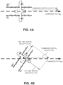
- this may be due to misalignment between the aerial vehicle's forward aerodynamic axis (also referred to herein as the vehicle's x-axis) and its flight vector (direction of inertial movement relative to Earth's frame of reference).
- the airspeed sensor is mounted to the aerial vehicle in an orientation that measures airspeed along its forward aerodynamic axis.
- the aerodynamic surfaces on the aerial vehicle cause a weathervane effect that aligns the forward aerodynamic axis of the aerial vehicle with its flight vector (see FIG. 4A ), resulting in an accurate airspeed measurement.
- an aerial vehicle may enter flight modes where the forward aerodynamic axis of the aerial vehicle is not well aligned with its flight vector (see FIG. 4B ). This is particularly true for vertical takeoff and landing (VTOL) vehicles when transitioning between a hover mode and cruising mode. This misalignment is usually short lived during the transition.
- VTOL vertical takeoff and landing
- the aerial vehicle may become unable to obtain sufficiently good airspeed measurements to facilitate an exit from the misaligned state, resulting in a lack of control authority, if control allocations are performed based on these airspeed measurements. As such, the aerial vehicle may become unable to accurately schedule gains and allocate control effort to exit this trapped state.
- commanded speed in lieu of a "sensed airspeed” to inform flight control decisions.
- the commanded speed is used as a reference point, such that quantities of thrust and torque applied are appropriate for the airspeed at which the aerial vehicle is being commended to travel, rather than its measured or estimated speed.
- the commanded speed may be specified relative to the airmass through which the aerial vehicle is flying or relative to Earth over which the aerial vehicle is flying.
- FIG. 1 is a perspective view illustration of an aerial vehicle 100, in accordance with an embodiment of the disclosure.
- the illustrated embodiment of aerial vehicle 100 is a VTOL unmanned aerial vehicle (UAV) that includes separate propulsion units 106 and 112 for providing horizontal and vertical propulsion, respectively.
- Aerial vehicle 100 is a fixed-wing aerial vehicle, which as the name implies, has a wing assembly 102 that can generate lift based on the wing shape and the vehicle's forward airspeed when propelled horizontally by propulsion units 106.
- aerial vehicle 100 has an airframe that includes a fuselage 104, wing assembly 102, and boom assemblies 110.
- fuselage 104 is modular and includes a battery module, an avionics module, and a mission payload module. These modules may be detachable from each other and mechanically securable to each other to contiguously form at least a portion of the fuselage or main body.
- the battery module includes a cavity for housing one or more batteries for powering aerial vehicle 100.
- the avionics module houses flight control circuitry of aerial vehicle 100, which may include a processor and memory, communication electronics and antennas (e.g., cellular transceiver, wifi transceiver, etc.), and various sensors (e.g., global positioning sensor, an inertial measurement unit (IMU), a magnetic compass, etc.).
- the mission payload module houses equipment associated with a mission of aerial vehicle 100.
- the mission payload module may include a payload actuator for holding and releasing an externally attached payload.
- the mission payload module may include a camera/sensor equipment holder for carrying camera/sensor equipment (e.g., camera, lenses, radar, lidar, pollution monitoring sensors, weather monitoring sensors, etc.).
- An airspeed sensor e.g., pitot probe
- aerial vehicle 100 includes horizontal propulsion units 106 positioned on wing assembly 102, which can each include a motor, a motor rotor with shaft, and propeller blades, for propelling aerial vehicle 100 horizontally.
- the illustrated embodiment of aerial vehicle 100 further includes two boom assemblies 110 that secure to wing assembly 102.
- Vertical propulsion units 112 are mounted to boom assemblies 110.
- Vertical propulsion units 112 can each also include a motor, a motor rotor with shaft, and propeller blades, for providing vertical propulsion.
- Vertical propulsion units 112 may be used during a hover mode where aerial vehicle 100 is descending (e.g., to a delivery location), ascending (e.g., following a delivery), or maintaining a constant altitude.
- Stabilizers 108 may be included with aerial vehicle 100 to control pitch and stabilize the aerial vehicle's yaw (left or right turns) during cruise.
- vertical propulsion units 112 are disabled and during hover horizontal propulsion units 106 are disabled.
- vertical propulsion units 112 are merely powered low during cruise mode and/or horizontal propulsion units 106 are merely powered low during hover mode.
- aerial vehicle 100 may control the direction and/or speed of its movement by controlling its pitch, roll, yaw, and/or altitude. Thrust from horizontal propulsion units 106 is used to control air speed as scheduled gains.
- the stabilizers 108 may include one or more rudders 108a for controlling the aerial vehicle's yaw, and wing assembly 102 may include elevators for controlling the aerial vehicle's pitch and/or ailerons 102a for controlling the aerial vehicle's roll. Control effort may be allocated via these control surfaces.
- increasing or decreasing the speed of all the propeller blades simultaneously can result in aerial vehicle 100 increasing or decreasing its altitude, respectively.
- FIG. 1 illustrates one wing assembly 102, two boom assemblies 110, two horizontal propulsion units 106, and four vertical propulsion units 112 per boom assembly 110, it should be appreciated that other variants of aerial vehicle 100 may be implemented with more or less of these components.
- the control techniques described herein are not limited to use with only VTOLs or UAVs, but rather these control techniques may be applicable to other types of aerial vehicles as well.
- references herein to an "unmanned" aerial vehicle or UAV can apply equally to autonomous and semi-autonomous aerial vehicles.
- all functionality of the aerial vehicle is automated; e.g., pre-programmed or controlled via real-time computer functionality that responds to input from various sensors and/or pre-determined information.
- some functions of an aerial vehicle may be controlled by a human operator, while other functions are carried out autonomously.
- a UAV may be configured to allow a remote operator to take over functions that can otherwise be controlled autonomously by the UAV.
- a given type of function may be controlled remotely at one level of abstraction and performed autonomously at another level of abstraction.
- a remote operator may control high level navigation decisions for a UAV, such as specifying that the UAV should travel from one location to another (e.g., from a warehouse in a suburban area to a delivery address in a nearby city), while the UAV's navigation system autonomously controls more fine-grained navigation decisions, such as the specific route to take between the two locations, specific flight controls to achieve the route and avoid obstacles while navigating the route, and so on.
- FIG. 2 illustrates a UAV 200 navigating a drone mission over a neighborhood 205 along a flight path including hover segments 210A and 210C and a cruise segment 210B.
- UAV 200 may be implemented by aerial vehicle 100, in one embodiment.
- the flight path is traversed by UAV 200 in response to a commanded path generated by a mission manager.
- the commanded path is the path that UAV 200 is commanded to follow by a control system, while the flight path is the actual path executed. In an ideal situation, these two paths are coincident, though in reality these paths may slightly deviate as the control system of UAV 200 strives to execute the commanded path despite real world influences like wind, turbulence, aerodynamic drag, rain, etc.
- the drone mission includes acceleration during hover segment 210A, a constant velocity during cruising segment 210B, and deacceleration to a destination 215 during hover segment 210C.
- UAV 200 commences its drone mission from a staging area 220 in a hover mode to traverse hover segment 210A.
- UAV 200 starts at a ground elevation, rises up to a cruising altitude, and then accelerates to a cruising speed before fully transitioning to a cruising mode for the cruising segment 210B of the flight path.
- the cruising speed is a fixed value (e.g., 50 mph).
- the fixed value may be selected based upon the design/type of UAV 200, the range of the particular drone mission, the weight/drag of a payload, battery constraints, or other factors and considerations.
- the fixed value when used for airspeed tracking, is an airspeed at which the aircraft is expected to travel.
- the fixed value may be used to select gains and control allocations appropriate for such a speed..
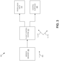
- FIG. 3 is a functional block diagram illustrating a control system 300 for UAV 200, in accordance with an embodiment of the disclosure.
- the illustrated embodiment of control system includes a mission manager 305 and flight control system 310, which provide control commands to propulsion units 315 and control surfaces 320.
- Propulsion units 315 may include one or both of horizontal propulsion units 106 and vertical propulsion units 112.
- Control surfaces 320 may include any of the control surfaces including ailerons 102a and rudders 108a, or other actuated control surfaces.
- mission manager 305 generates a commanded inertial velocity 405, which points along commanded path 410 (also generated by mission manager 305).
- Commanded inertial velocity 405 is a vector quantity (magnitude and direction), and should be interpreted as a commanded velocity relative to an inertial reference frame (e.g., Earth's frame of reference).
- Flight control system 310 breaks down commanded inertial velocity 405 into two components: a forward commanded inertial velocity ( v xci ) and a lateral commanded inertial velocity ( V_yci ) .
- the "x” and “y” correspond to directions relative to the aircraft's body frame: x-forward axis 206 and y-lateral axis 207.
- the “c” refers to the fact that these quantities are commands, rather than estimates of a current state.
- the "i” refers to "inertial.”
- a placeholder value referred to as a "forward commanded velocity" ( Y_xc ) is defined.
- V_xc is set to equal the forward commanded inertial velocity V_xci.
- V_xc is instead set to a fixed value associated with the cruising mode.
- the fixed value may be considered a commanded airspeed (as opposed to a commanded velocity with directional information) for cruising. In one embodiment, this fixed value is a preset defined parameter of the aircraft.
- the subscript "i" is dropped from V_xc to emphasize this distinction.
- a flight control system references a sensed airspeed to schedule gains and allocate control effort.
- flight control system 310 instead contingently uses cmd_speed to schedule gains and allocate control effort.
- flight control system 310 contingently references cmd speed in lieu of sensed airspeed to inform flight control decisions according to expression 2: max cmd _ speed , sensed _ airspeed , where sensed airspeed is the airspeed as measured by an onboard sensor of the UAV. Accordingly, in one embodiment, flight control system 310 uses the maximum value selected between cmd speed and sensed airspeed, rather than just using a measured airspeed.
- Ex. 2 During acceleration (e.g., hover mode), using Ex. 2 to inform flight control decisions adds robustness when sensed airspeed is artificially low due to poor alignment of the sensor with direction of travel through the airmass. The larger value of cmd_speed is instead used, which provides an appropriate value upon which to schedule gains.
- constant speed cruising e.g., cruising mode
- using Ex. 2 to inform flight control decisions adds robustness when the vehicle becomes misaligned from its commanded path 410 (see FIG. 4B ) due to disturbances. In this scenario, Ex. 2 provides a larger value, relative to an artificially suppressed sensed airspeed. This larger value is more appropriate for the cruising flight.
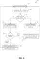
- FIG. 5 is a flow chart illustrating a process 500 for selectively substituting a commanded speed ( cmd_speed ) for a sensed airspeed ( sensed_airspeed ) to inform flight control decisions of UAV 200, in accordance with an embodiment of the disclosure.
- cmd_speed commanded speed
- sensed_airspeed sensed airspeed
- flight control system 310 monitors the sensed airspeed ( sensed_airspeed ) from an onboard airspeed sensor.
- flight control system 310 obtains the commanded speed ( cmd_speed ). In one embodiment, the commanded speed is calculated based upon Eq. 1. If flight control system 310 determines that sensed airspeed is larger than cmd speed, then process 500 continues to process block 520 where flight control system 310 uses sensed airspeed to inform its flight control decisions to keep UAV 100 tracking commanded path 410.
- process 500 continues to a process block 525 and contingently uses the commanded speed (see Eq. 1) in lieu of sensed airspeed to inform flight control decisions of UAV 200. If UAV 200 is operating in a cruising mode (decision block 530), then the forward commanded velocity ( Y_xc ) is set to a preset fixed value associated with cruising for UAV 200 (process block 535).
- the forward commanded velocity ( V_xc ) is set to a forward commanded inertial velocity ( V_xci ) calculated by flight control system 310 as a forward component of the commanded inertial velocity 405 provided by mission manager 305.
- the forward component is the projection of commanded inertial velocity 405 on to commanded path 410.
- a tangible machine-readable storage medium includes any mechanism that provides (i.e., stores) information in a non-transitory form accessible by a machine (e.g., a computer, network device, personal digital assistant, manufacturing tool, any device with a set of one or more processors, etc.).
- a machine-readable storage medium includes recordable/non-recordable media (e.g., read only memory (ROM), random access memory (RAM), magnetic disk storage media, optical storage media, flash memory devices, etc.).
Landscapes
- Engineering & Computer Science (AREA)
- Aviation & Aerospace Engineering (AREA)
- Remote Sensing (AREA)
- Combustion & Propulsion (AREA)
- Mechanical Engineering (AREA)
- Chemical & Material Sciences (AREA)
- Radar, Positioning & Navigation (AREA)
- Physics & Mathematics (AREA)
- General Physics & Mathematics (AREA)
- Automation & Control Theory (AREA)
- Microelectronics & Electronic Packaging (AREA)
- Computer Security & Cryptography (AREA)
- Control Of Position, Course, Altitude, Or Attitude Of Moving Bodies (AREA)
Claims (8)
- Verfahren für ein Steuern eines unbemannten Luftfahrzeugs (UAV), das Verfahren umfassend:Überwachen einer erfassten Fluggeschwindigkeit des UAV (100; 200);Erhalten einer befohlenen Geschwindigkeit für das UAV, die befohlene Geschwindigkeit einen Befehl für ein Fliegen des UAV mit einer in Bezug auf eine Luftmasse, durch die das UAV fliegt, oder auf die Erde, über die das UAV fliegt, betreffenden Geschwindigkeit darstellt,dadurch gekennzeichnet, dass ein Erhalten der befohlenen Geschwindigkeit für das UAV ein Berechnen der befohlenen Geschwindigkeit (cmd_speed) umfasst als:
 wobei V_xc eine befohlene Vorwärtsgeschwindigkeit für das UAV darstellt und V_yci eine seitlich befohlene Trägheitsgeschwindigkeit für das UAV darstellt, die seitlich befohlene Trägheitsgeschwindigkeit als eine seitliche Komponente einer befohlenen Trägheitsgeschwindigkeit berechnet wird, die entlang eines befohlenen Pfades für das UAV zeigt;wenn die befohlene Geschwindigkeit größer als die erfasste Fluggeschwindigkeit ist, Nutzen der befohlenen Geschwindigkeit anstelle der erfassten Fluggeschwindigkeit für ein Planen des Schubs für den Antrieb des UAV und/oder Zuweisen von Steuerungsaufwand für eine Steuerfläche (320) des UAV; undwenn die erfasste Fluggeschwindigkeit größer ist als die befohlene Geschwindigkeit, Nutzen der erfassten Fluggeschwindigkeit anstelle der befohlenen Geschwindigkeit für ein Planen des Schubs für den Antrieb des UAV und/oder Zuweisen von Steuerungsaufwand für die Steuerfläche des UAV.
 - Verfahren nach Anspruch 1, wobei die erfasste Fluggeschwindigkeit des UAV eine Messung der Fluggeschwindigkeit umfasst, wie sie von einem integrierten Sensor des UAV während des Fluges erfasst wird.
- Verfahren nach Anspruch 1, ferner umfassend:
wenn das UAV in einem Reiseflugmodus betrieben wird, Setzen der befohlenen Vorwärtsgeschwindigkeit auf einen festen Wert, der mit dem Reiseflugmodus des UAVs assoziiert ist. - Verfahren nach Anspruch 3, ferner umfassend:
wenn das UAV in einem Schwebemodus betrieben wird, der eine Beschleunigung in den Reiseflugmodus und eine Abbremsung aus dem Reiseflugmodus umfasst, Setzen der befohlenen Vorwärtsgeschwindigkeit auf eine befohlene Vorwärtsträgheitsgeschwindigkeit für das UAV, die als eine Vorwärtskomponente der befohlenen Trägheitsgeschwindigkeit berechnet wird, die entlang des befohlenen Pfades für das UAV zeigt. - Verfahren nach Anspruch 1, wobei das UAV ein vertikal startendes und landendes (VTOL-)UAV umfasst, das mindestens eine vertikale Antriebseinheit und mindestens eine horizontale Antriebseinheit umfasst.
- Mindestens ein maschinenzugängliches Speichermedium, das Anweisungen bereitstellt, die, bei Ausführung durch ein Steuersystem (310) eines unbemannten Luftfahrzeugs (UAV), das UAV (100; 200) veranlassen, Operationen durchzuführen, die das Verfahren nach einem der Ansprüche 1-5 umfassen.
- Unbemanntes Luftfahrzeug (UAV), umfassend:eine Steuerfläche (320) für ein Beeinflussen eines oder mehrere von einer Steigung, eines Gierens oder eines Rollens des UAV (100; 200);eine Antriebseinheit (315), um das UAV anzutreiben;einen Sensor für ein Messen einer Fluggeschwindigkeit des UAV und in Reaktion Ausgeben einer erfassten Fluggeschwindigkeit für das UAV; undein Steuersystem (310), das mit der Steuerfläche, der Antriebseinheit und dem Sensor gekoppelt ist, das Steuersystem eine Logik umfassend, die, bei Ausführung durch das Steuersystem, das UAV veranlasst, Operationen durchzuführen, einschließlich:Erhalten einer befohlenen Geschwindigkeit für das UAV, die befohlene Geschwindigkeit einen Befehl für ein Fliegen des UAV mit einer in Bezug auf eine Luftmasse, durch die das UAV fliegt, oder auf die Erde, über die das UAV fliegt, betreffenden Geschwindigkeit darstellt,dadurch gekennzeichnet, dassein Erhalten der befohlenen Geschwindigkeit für das UAV ein Berechnen der befohlenen Geschwindigkeit (cmd_speed) umfasst als:
 wobei V_xc eine befohlene Vorwärtsgeschwindigkeit für das UAV darstellt und V_yci eine seitlich befohlene Trägheitsgeschwindigkeit für das UAV darstellt, die seitlich befohlene Trägheitsgeschwindigkeit als eine seitliche Komponente einer befohlenen Trägheitsgeschwindigkeit berechnet wird, die entlang eines befohlenen Pfades für das UAV zeigt;wenn die befohlene Geschwindigkeit größer als die erfasste Fluggeschwindigkeit ist, Nutzen der befohlenen Geschwindigkeit anstelle der erfassten Fluggeschwindigkeit für ein Planen des Schubs für die Antriebseinheit und/oder Zuweisen von Steueraufwand für die Steuerfläche; undwenn die erfasste Fluggeschwindigkeit größer ist als die befohlene Geschwindigkeit, Nutzen der erfassten Fluggeschwindigkeit anstelle der befohlenen Geschwindigkeit für ein Planen des Schubs für den Antrieb des UAV und/oder Zuweisen von Steuerungsaufwand für die Steuerfläche des UAV.
 - UAV nach Anspruch 7, wobei das Steuersystem ferner eine Logik umfasst, die, bei Ausführung durch das Steuersystem, das UAV veranlasst, weitere Operationen durchzuführen, einschließlich:wenn das UAV in einem Reiseflugmodus betrieben wird, Setzen der befohlenen Vorwärtsgeschwindigkeit auf einen festen Wert; undwenn das UAV in einem Schwebemodus betrieben wird, der eine Beschleunigung in den Reiseflugmodus und eine Abbremsung aus dem Reiseflugmodus umfasst, Setzen der befohlenen Vorwärtsgeschwindigkeit auf eine befohlene Vorwärtsträgheitsgeschwindigkeit für das UAV, die als eine Vorwärtskomponente der befohlenen Trägheitsgeschwindigkeit berechnet wird, die entlang des befohlenen Pfades für das UAV zeigt.
Applications Claiming Priority (2)
| Application Number | Priority Date | Filing Date | Title |
|---|---|---|---|
| US16/597,338 US11507115B2 (en) | 2019-10-09 | 2019-10-09 | Contingent use of commanded speed in lieu of sensed airspeed to inform flight control decisions |
| PCT/US2020/053416 WO2021071707A1 (en) | 2019-10-09 | 2020-09-30 | Contingent use of commanded speed in lieu of sensed airspeed to inform flight control decisions |
Publications (3)
| Publication Number | Publication Date |
|---|---|
| EP4038464A1 EP4038464A1 (de) | 2022-08-10 |
| EP4038464A4 EP4038464A4 (de) | 2023-12-06 |
| EP4038464B1 true EP4038464B1 (de) | 2025-05-07 |
Family
ID=75382820
Family Applications (1)
| Application Number | Title | Priority Date | Filing Date |
|---|---|---|---|
| EP20873742.9A Active EP4038464B1 (de) | 2019-10-09 | 2020-09-30 | Kontinuierliche verwendung der sollgeschwindigkeit anstelle der gemessenen fluggeschwindigkeit für flugsteuerungsentscheidungen |
Country Status (5)
| Country | Link |
|---|---|
| US (1) | US11507115B2 (de) |
| EP (1) | EP4038464B1 (de) |
| CN (1) | CN114556250B (de) |
| AU (1) | AU2020364319B2 (de) |
| WO (1) | WO2021071707A1 (de) |
Families Citing this family (2)
| Publication number | Priority date | Publication date | Assignee | Title |
|---|---|---|---|---|
| USD996339S1 (en) * | 2021-04-16 | 2023-08-22 | Sierra Nevada Corporation | Aircraft |
| CN115454148B (zh) * | 2022-11-08 | 2023-02-17 | 四川腾盾科技有限公司 | 固定翼集群无人机区域覆盖路径规划方法、介质及装置 |
Family Cites Families (17)
| Publication number | Priority date | Publication date | Assignee | Title |
|---|---|---|---|---|
| US4633404A (en) * | 1983-05-20 | 1986-12-30 | Sperry Corporation | Automatic deceleration of aircraft during descent |
| JPH0741878B2 (ja) * | 1990-09-21 | 1995-05-10 | 防衛庁技術研究本部長 | 目標ホバリング点への自動飛行制御システム及び方法 |
| AU2001264662A1 (en) | 2000-05-17 | 2001-11-26 | Abraham E. Karem | Intuitive vehicle and machine control |
| CN100519337C (zh) * | 2005-09-12 | 2009-07-29 | 贝尔直升机泰克斯特龙公司 | 飞行器以及飞行器的自动速度控制系统和方法 |
| CA2591713C (en) | 2005-11-15 | 2013-07-16 | Bell Helicopter Textron, Inc. | Control system for automatic circle flight |
| US7410122B2 (en) * | 2006-03-20 | 2008-08-12 | The Boeing Company | VTOL UAV with lift fans in joined wings |
| US7571879B2 (en) | 2006-09-22 | 2009-08-11 | Bell Helicopter Textron Inc. | Automatic conversion system for tiltrotor aircraft |
| US20110184592A1 (en) * | 2010-01-26 | 2011-07-28 | Honeywell International Inc. | Alternate airspeed computation when air data computer (adc) fails |
| CN102763049B (zh) * | 2010-02-11 | 2016-02-03 | 贝尔直升机泰克斯特龙公司 | 失速防止/恢复的系统和方法 |
| KR101740312B1 (ko) | 2015-01-09 | 2017-06-09 | 주식회사 대한항공 | 무인 항공기의 카메라 조종정보를 이용한 무인 항공기 유도제어 방법 |
| US9365290B1 (en) | 2015-08-27 | 2016-06-14 | Martin Uav, Llc | Vertical take off aircraft |
| US11453494B2 (en) | 2016-05-20 | 2022-09-27 | Skydio, Inc. | Unmanned aerial vehicle area surveying |
| US10562623B1 (en) * | 2016-10-21 | 2020-02-18 | Birdseyeview Aerobotics, Llc | Remotely controlled VTOL aircraft |
| US10481615B2 (en) * | 2017-03-01 | 2019-11-19 | Bell Textron Inc. | Rotorcraft control mode transition smoothing |
| US20190039720A1 (en) * | 2017-08-07 | 2019-02-07 | Bell Helicopter Textron Inc. | System and Method for Rotorcraft Approach to Hover |
| US10175698B1 (en) * | 2017-09-11 | 2019-01-08 | Honeywell International Inc. | Automatic flight control systems and methods |
| US11091260B2 (en) * | 2018-04-27 | 2021-08-17 | Wing Aviation Llc | Counter-rotating propellers for aerial vehicle |
-
2019
- 2019-10-09 US US16/597,338 patent/US11507115B2/en active Active
-
2020
- 2020-09-30 WO PCT/US2020/053416 patent/WO2021071707A1/en not_active Ceased
- 2020-09-30 AU AU2020364319A patent/AU2020364319B2/en active Active
- 2020-09-30 CN CN202080070925.7A patent/CN114556250B/zh active Active
- 2020-09-30 EP EP20873742.9A patent/EP4038464B1/de active Active
Also Published As
| Publication number | Publication date |
|---|---|
| US20210109550A1 (en) | 2021-04-15 |
| EP4038464A4 (de) | 2023-12-06 |
| EP4038464A1 (de) | 2022-08-10 |
| US11507115B2 (en) | 2022-11-22 |
| AU2020364319A1 (en) | 2022-03-31 |
| WO2021071707A1 (en) | 2021-04-15 |
| CN114556250A (zh) | 2022-05-27 |
| AU2020364319B2 (en) | 2023-12-21 |
| CN114556250B (zh) | 2025-08-08 |
Similar Documents
| Publication | Publication Date | Title |
|---|---|---|
| US10513341B2 (en) | Thrust allocation for aerial vehicle | |
| Gu et al. | Development and experimental verification of a hybrid vertical take-off and landing (VTOL) unmanned aerial vehicle (UAV) | |
| Verling et al. | Full attitude control of a VTOL tailsitter UAV | |
| AU2017386252B2 (en) | Rotor units having asymmetric rotor blades | |
| NL2017971B1 (en) | Unmanned aerial vehicle | |
| NL2018003B1 (en) | Unmanned aerial vehicle | |
| US11858626B2 (en) | Autonomous air vehicle delivery system incorporating deployment | |
| Ostermann et al. | Control concept of a tiltwing uav during low speed manoeuvring | |
| EP4038464B1 (de) | Kontinuierliche verwendung der sollgeschwindigkeit anstelle der gemessenen fluggeschwindigkeit für flugsteuerungsentscheidungen | |
| JP7770700B2 (ja) | 飛行体の着陸方法、飛行体、情報処理装置、プログラム | |
| Ma et al. | Design and control of a tilt-rotor tailsitter aircraft with pivoting vtol capability | |
| US20230192290A1 (en) | Uav with augmented lift rotors | |
| Johansen et al. | Guidance, Navigation, and Control of Fixed-Wing Unmanned Aerial Vehicles | |
| Hwang et al. | AOSoar: Autonomous Orographic Soaring of a Micro Air Vehicle | |
| Olejnik et al. | Specific problems of selecting and integrating equipment components in the course of developing a technology demonstrator for the mini-UAV | |
| CN119105535B (zh) | 一种垂直起落无人机的控制方法及系统 | |
| US12525135B2 (en) | UAV flight control operations for predicted traffic encounter | |
| US20260057788A1 (en) | Contingency Response Operations for Flight Paths | |
| US20260056551A1 (en) | Generating Power and Energy Predictions for Flight Paths | |
| Juanxia et al. | Multimode Controller design and flight test for Tailsitter UAV without elevon |
Legal Events
| Date | Code | Title | Description |
|---|---|---|---|
| STAA | Information on the status of an ep patent application or granted ep patent |
Free format text: STATUS: THE INTERNATIONAL PUBLICATION HAS BEEN MADE |
|
| PUAI | Public reference made under article 153(3) epc to a published international application that has entered the european phase |
Free format text: ORIGINAL CODE: 0009012 |
|
| STAA | Information on the status of an ep patent application or granted ep patent |
Free format text: STATUS: REQUEST FOR EXAMINATION WAS MADE |
|
| 17P | Request for examination filed |
Effective date: 20220505 |
|
| AK | Designated contracting states |
Kind code of ref document: A1 Designated state(s): AL AT BE BG CH CY CZ DE DK EE ES FI FR GB GR HR HU IE IS IT LI LT LU LV MC MK MT NL NO PL PT RO RS SE SI SK SM TR |
|
| DAV | Request for validation of the european patent (deleted) | ||
| DAX | Request for extension of the european patent (deleted) | ||
| REG | Reference to a national code |
Ref country code: DE Free format text: PREVIOUS MAIN CLASS: G05D0001000000 Ref country code: DE Ref legal event code: R079 Ref document number: 602020051054 Country of ref document: DE Free format text: PREVIOUS MAIN CLASS: G05D0001000000 Ipc: G05D0001020000 |
|
| A4 | Supplementary search report drawn up and despatched |
Effective date: 20231107 |
|
| RIC1 | Information provided on ipc code assigned before grant |
Ipc: B64C 39/02 20060101ALI20231031BHEP Ipc: G05D 1/02 20200101AFI20231031BHEP |
|
| STAA | Information on the status of an ep patent application or granted ep patent |
Free format text: STATUS: EXAMINATION IS IN PROGRESS |
|
| 17Q | First examination report despatched |
Effective date: 20240709 |
|
| REG | Reference to a national code |
Ref country code: DE Ref legal event code: R079 Free format text: PREVIOUS MAIN CLASS: G05D0001020000 Ipc: G05D0001000000 Ref country code: DE Ref legal event code: R079 Ref document number: 602020051054 Country of ref document: DE Free format text: PREVIOUS MAIN CLASS: G05D0001020000 Ipc: G05D0001000000 |
|
| GRAP | Despatch of communication of intention to grant a patent |
Free format text: ORIGINAL CODE: EPIDOSNIGR1 |
|
| STAA | Information on the status of an ep patent application or granted ep patent |
Free format text: STATUS: GRANT OF PATENT IS INTENDED |
|
| RIC1 | Information provided on ipc code assigned before grant |
Ipc: B64U 50/30 20230101ALI20241217BHEP Ipc: B64U 50/19 20230101ALI20241217BHEP Ipc: B64U 30/10 20230101ALI20241217BHEP Ipc: B64U 20/80 20230101ALI20241217BHEP Ipc: B64U 10/20 20230101ALI20241217BHEP Ipc: G05D 1/00 20060101AFI20241217BHEP |
|
| INTG | Intention to grant announced |
Effective date: 20250109 |
|
| GRAS | Grant fee paid |
Free format text: ORIGINAL CODE: EPIDOSNIGR3 |
|
| GRAA | (expected) grant |
Free format text: ORIGINAL CODE: 0009210 |
|
| STAA | Information on the status of an ep patent application or granted ep patent |
Free format text: STATUS: THE PATENT HAS BEEN GRANTED |
|
| RAP3 | Party data changed (applicant data changed or rights of an application transferred) |
Owner name: WING AVIATION LLC |
|
| AK | Designated contracting states |
Kind code of ref document: B1 Designated state(s): AL AT BE BG CH CY CZ DE DK EE ES FI FR GB GR HR HU IE IS IT LI LT LU LV MC MK MT NL NO PL PT RO RS SE SI SK SM TR |
|
| P01 | Opt-out of the competence of the unified patent court (upc) registered |
Free format text: CASE NUMBER: APP_14964/2025 Effective date: 20250327 |
|
| REG | Reference to a national code |
Ref country code: GB Ref legal event code: FG4D |
|
| REG | Reference to a national code |
Ref country code: CH Ref legal event code: EP |
|
| REG | Reference to a national code |
Ref country code: DE Ref legal event code: R096 Ref document number: 602020051054 Country of ref document: DE |
|
| REG | Reference to a national code |
Ref country code: IE Ref legal event code: FG4D |
|
| REG | Reference to a national code |
Ref country code: NL Ref legal event code: MP Effective date: 20250507 |
|
| REG | Reference to a national code |
Ref country code: CH Ref legal event code: U11 Free format text: ST27 STATUS EVENT CODE: U-0-0-U10-U11 (AS PROVIDED BY THE NATIONAL OFFICE) Effective date: 20251001 |
|
| PG25 | Lapsed in a contracting state [announced via postgrant information from national office to epo] |
Ref country code: PT Free format text: LAPSE BECAUSE OF FAILURE TO SUBMIT A TRANSLATION OF THE DESCRIPTION OR TO PAY THE FEE WITHIN THE PRESCRIBED TIME-LIMIT Effective date: 20250908 Ref country code: ES Free format text: LAPSE BECAUSE OF FAILURE TO SUBMIT A TRANSLATION OF THE DESCRIPTION OR TO PAY THE FEE WITHIN THE PRESCRIBED TIME-LIMIT Effective date: 20250507 Ref country code: FI Free format text: LAPSE BECAUSE OF FAILURE TO SUBMIT A TRANSLATION OF THE DESCRIPTION OR TO PAY THE FEE WITHIN THE PRESCRIBED TIME-LIMIT Effective date: 20250507 |
|
| PGFP | Annual fee paid to national office [announced via postgrant information from national office to epo] |
Ref country code: DE Payment date: 20250926 Year of fee payment: 6 |
|
| REG | Reference to a national code |
Ref country code: LT Ref legal event code: MG9D |
|
| PG25 | Lapsed in a contracting state [announced via postgrant information from national office to epo] |
Ref country code: GR Free format text: LAPSE BECAUSE OF FAILURE TO SUBMIT A TRANSLATION OF THE DESCRIPTION OR TO PAY THE FEE WITHIN THE PRESCRIBED TIME-LIMIT Effective date: 20250808 Ref country code: NO Free format text: LAPSE BECAUSE OF FAILURE TO SUBMIT A TRANSLATION OF THE DESCRIPTION OR TO PAY THE FEE WITHIN THE PRESCRIBED TIME-LIMIT Effective date: 20250807 |
|
| PG25 | Lapsed in a contracting state [announced via postgrant information from national office to epo] |
Ref country code: PL Free format text: LAPSE BECAUSE OF FAILURE TO SUBMIT A TRANSLATION OF THE DESCRIPTION OR TO PAY THE FEE WITHIN THE PRESCRIBED TIME-LIMIT Effective date: 20250507 Ref country code: NL Free format text: LAPSE BECAUSE OF FAILURE TO SUBMIT A TRANSLATION OF THE DESCRIPTION OR TO PAY THE FEE WITHIN THE PRESCRIBED TIME-LIMIT Effective date: 20250507 |
|
| REG | Reference to a national code |
Ref country code: AT Ref legal event code: MK05 Ref document number: 1793164 Country of ref document: AT Kind code of ref document: T Effective date: 20250507 |
|
| PG25 | Lapsed in a contracting state [announced via postgrant information from national office to epo] |
Ref country code: BG Free format text: LAPSE BECAUSE OF FAILURE TO SUBMIT A TRANSLATION OF THE DESCRIPTION OR TO PAY THE FEE WITHIN THE PRESCRIBED TIME-LIMIT Effective date: 20250507 |
|
| PGFP | Annual fee paid to national office [announced via postgrant information from national office to epo] |
Ref country code: GB Payment date: 20250923 Year of fee payment: 6 |
|
| PG25 | Lapsed in a contracting state [announced via postgrant information from national office to epo] |
Ref country code: HR Free format text: LAPSE BECAUSE OF FAILURE TO SUBMIT A TRANSLATION OF THE DESCRIPTION OR TO PAY THE FEE WITHIN THE PRESCRIBED TIME-LIMIT Effective date: 20250507 |
|
| PG25 | Lapsed in a contracting state [announced via postgrant information from national office to epo] |
Ref country code: AT Free format text: LAPSE BECAUSE OF FAILURE TO SUBMIT A TRANSLATION OF THE DESCRIPTION OR TO PAY THE FEE WITHIN THE PRESCRIBED TIME-LIMIT Effective date: 20250507 |
|
| PGFP | Annual fee paid to national office [announced via postgrant information from national office to epo] |
Ref country code: FR Payment date: 20250925 Year of fee payment: 6 |
|
| PG25 | Lapsed in a contracting state [announced via postgrant information from national office to epo] |
Ref country code: RS Free format text: LAPSE BECAUSE OF FAILURE TO SUBMIT A TRANSLATION OF THE DESCRIPTION OR TO PAY THE FEE WITHIN THE PRESCRIBED TIME-LIMIT Effective date: 20250807 |
|
| PGFP | Annual fee paid to national office [announced via postgrant information from national office to epo] |
Ref country code: IE Payment date: 20250917 Year of fee payment: 6 |
|
| PG25 | Lapsed in a contracting state [announced via postgrant information from national office to epo] |
Ref country code: IS Free format text: LAPSE BECAUSE OF FAILURE TO SUBMIT A TRANSLATION OF THE DESCRIPTION OR TO PAY THE FEE WITHIN THE PRESCRIBED TIME-LIMIT Effective date: 20250907 |
|
| PG25 | Lapsed in a contracting state [announced via postgrant information from national office to epo] |
Ref country code: LV Free format text: LAPSE BECAUSE OF FAILURE TO SUBMIT A TRANSLATION OF THE DESCRIPTION OR TO PAY THE FEE WITHIN THE PRESCRIBED TIME-LIMIT Effective date: 20250507 |
|
| PG25 | Lapsed in a contracting state [announced via postgrant information from national office to epo] |
Ref country code: DK Free format text: LAPSE BECAUSE OF FAILURE TO SUBMIT A TRANSLATION OF THE DESCRIPTION OR TO PAY THE FEE WITHIN THE PRESCRIBED TIME-LIMIT Effective date: 20250507 Ref country code: SM Free format text: LAPSE BECAUSE OF FAILURE TO SUBMIT A TRANSLATION OF THE DESCRIPTION OR TO PAY THE FEE WITHIN THE PRESCRIBED TIME-LIMIT Effective date: 20250507 |
|
| PGFP | Annual fee paid to national office [announced via postgrant information from national office to epo] |
Ref country code: CH Payment date: 20251001 Year of fee payment: 6 |
|
| PG25 | Lapsed in a contracting state [announced via postgrant information from national office to epo] |
Ref country code: CZ Free format text: LAPSE BECAUSE OF FAILURE TO SUBMIT A TRANSLATION OF THE DESCRIPTION OR TO PAY THE FEE WITHIN THE PRESCRIBED TIME-LIMIT Effective date: 20250507 |
|
| PG25 | Lapsed in a contracting state [announced via postgrant information from national office to epo] |
Ref country code: EE Free format text: LAPSE BECAUSE OF FAILURE TO SUBMIT A TRANSLATION OF THE DESCRIPTION OR TO PAY THE FEE WITHIN THE PRESCRIBED TIME-LIMIT Effective date: 20250507 |
|
| PG25 | Lapsed in a contracting state [announced via postgrant information from national office to epo] |
Ref country code: SK Free format text: LAPSE BECAUSE OF FAILURE TO SUBMIT A TRANSLATION OF THE DESCRIPTION OR TO PAY THE FEE WITHIN THE PRESCRIBED TIME-LIMIT Effective date: 20250507 |
|
| PG25 | Lapsed in a contracting state [announced via postgrant information from national office to epo] |
Ref country code: IT Free format text: LAPSE BECAUSE OF FAILURE TO SUBMIT A TRANSLATION OF THE DESCRIPTION OR TO PAY THE FEE WITHIN THE PRESCRIBED TIME-LIMIT Effective date: 20250507 |
|
| PG25 | Lapsed in a contracting state [announced via postgrant information from national office to epo] |
Ref country code: RO Free format text: LAPSE BECAUSE OF FAILURE TO SUBMIT A TRANSLATION OF THE DESCRIPTION OR TO PAY THE FEE WITHIN THE PRESCRIBED TIME-LIMIT Effective date: 20250507 |
|
| REG | Reference to a national code |
Ref country code: DE Ref legal event code: R097 Ref document number: 602020051054 Country of ref document: DE |
|
| PLBE | No opposition filed within time limit |
Free format text: ORIGINAL CODE: 0009261 |
|
| STAA | Information on the status of an ep patent application or granted ep patent |
Free format text: STATUS: NO OPPOSITION FILED WITHIN TIME LIMIT |
|
| REG | Reference to a national code |
Ref country code: CH Ref legal event code: L10 Free format text: ST27 STATUS EVENT CODE: U-0-0-L10-L00 (AS PROVIDED BY THE NATIONAL OFFICE) Effective date: 20260318 |
|
| 26N | No opposition filed |
Effective date: 20260210 |