EP4038324B1 - An electric gas heater device and a system of electric gas heater devices - Google Patents
An electric gas heater device and a system of electric gas heater devices Download PDFInfo
- Publication number
- EP4038324B1 EP4038324B1 EP20893211.1A EP20893211A EP4038324B1 EP 4038324 B1 EP4038324 B1 EP 4038324B1 EP 20893211 A EP20893211 A EP 20893211A EP 4038324 B1 EP4038324 B1 EP 4038324B1
- Authority
- EP
- European Patent Office
- Prior art keywords
- outer tube
- center element
- gas heater
- electric
- elongated center
- Prior art date
- Legal status (The legal status is an assumption and is not a legal conclusion. Google has not performed a legal analysis and makes no representation as to the accuracy of the status listed.)
- Active
Links
Images



Classifications
-
- H—ELECTRICITY
- H05—ELECTRIC TECHNIQUES NOT OTHERWISE PROVIDED FOR
- H05B—ELECTRIC HEATING; ELECTRIC LIGHT SOURCES NOT OTHERWISE PROVIDED FOR; CIRCUIT ARRANGEMENTS FOR ELECTRIC LIGHT SOURCES, IN GENERAL
- H05B3/00—Ohmic-resistance heating
- H05B3/40—Heating elements having the shape of rods or tubes
- H05B3/42—Heating elements having the shape of rods or tubes non-flexible
-
- F—MECHANICAL ENGINEERING; LIGHTING; HEATING; WEAPONS; BLASTING
- F24—HEATING; RANGES; VENTILATING
- F24H—FLUID HEATERS, e.g. WATER OR AIR HEATERS, HAVING HEAT-GENERATING MEANS, e.g. HEAT PUMPS, IN GENERAL
- F24H3/00—Air heaters
- F24H3/02—Air heaters with forced circulation
- F24H3/04—Air heaters with forced circulation the air being in direct contact with the heating medium, e.g. electric heating element
- F24H3/0405—Air heaters with forced circulation the air being in direct contact with the heating medium, e.g. electric heating element using electric energy supply, e.g. the heating medium being a resistive element; Heating by direct contact, i.e. with resistive elements, electrodes and fins being bonded together without additional element in-between
-
- F—MECHANICAL ENGINEERING; LIGHTING; HEATING; WEAPONS; BLASTING
- F24—HEATING; RANGES; VENTILATING
- F24H—FLUID HEATERS, e.g. WATER OR AIR HEATERS, HAVING HEAT-GENERATING MEANS, e.g. HEAT PUMPS, IN GENERAL
- F24H9/00—Details
- F24H9/0052—Details for air heaters
- F24H9/0057—Guiding means
- F24H9/0063—Guiding means in air channels
-
- F—MECHANICAL ENGINEERING; LIGHTING; HEATING; WEAPONS; BLASTING
- F24—HEATING; RANGES; VENTILATING
- F24H—FLUID HEATERS, e.g. WATER OR AIR HEATERS, HAVING HEAT-GENERATING MEANS, e.g. HEAT PUMPS, IN GENERAL
- F24H9/00—Details
- F24H9/18—Arrangement or mounting of grates or heating means
- F24H9/1854—Arrangement or mounting of grates or heating means for air heaters
- F24H9/1863—Arrangement or mounting of electric heating means
-
- F—MECHANICAL ENGINEERING; LIGHTING; HEATING; WEAPONS; BLASTING
- F24—HEATING; RANGES; VENTILATING
- F24H—FLUID HEATERS, e.g. WATER OR AIR HEATERS, HAVING HEAT-GENERATING MEANS, e.g. HEAT PUMPS, IN GENERAL
- F24H9/00—Details
- F24H9/20—Arrangement or mounting of control or safety devices
- F24H9/2064—Arrangement or mounting of control or safety devices for air heaters
- F24H9/2071—Arrangement or mounting of control or safety devices for air heaters using electrical energy supply
-
- F—MECHANICAL ENGINEERING; LIGHTING; HEATING; WEAPONS; BLASTING
- F24—HEATING; RANGES; VENTILATING
- F24H—FLUID HEATERS, e.g. WATER OR AIR HEATERS, HAVING HEAT-GENERATING MEANS, e.g. HEAT PUMPS, IN GENERAL
- F24H15/00—Control of fluid heaters
- F24H15/20—Control of fluid heaters characterised by control inputs
- F24H15/25—Temperature of the heat-generating means in the heater
-
- F—MECHANICAL ENGINEERING; LIGHTING; HEATING; WEAPONS; BLASTING
- F24—HEATING; RANGES; VENTILATING
- F24H—FLUID HEATERS, e.g. WATER OR AIR HEATERS, HAVING HEAT-GENERATING MEANS, e.g. HEAT PUMPS, IN GENERAL
- F24H15/00—Control of fluid heaters
- F24H15/30—Control of fluid heaters characterised by control outputs; characterised by the components to be controlled
- F24H15/355—Control of heat-generating means in heaters
- F24H15/37—Control of heat-generating means in heaters of electric heaters
Definitions
- the present disclosure relates to an electric gas heater device, and in particular to a gas heater device providing efficient heating of a gas channel.
- the elements used must have a large surface area in order to provide an efficient convective heat transfer to the gas.
- the heat transfer efficiency will depend on the temperature difference between the surface of the element and the gas to be heated and there is always a limit to how hot the heating element can become before failure.
- the heat transfer to the gas will deteriorate as the gas temperature is approaching the maximum element temperature.
- the density and viscosity of gas to be heated also tend to change with increasing temperature which means that efficient convective heat transfer becomes more difficult.
- Another proposed method for electrically heating a gas is to conduct the gas through at least one tube that is resistively heated by connecting both ends of the tube to an electrical power source.
- One problem with such a solution is that the heat transfer area will be limited to the inner surface area of the tube. A large length of the pipe will therefore be required in order to heat the gas passing through it to a high temperature.
- Yet another problem is that there will be electromagnetically forces between parallel tubes in a larger assembly. These forces may cause problems such as bending and dislocation of the tubes and may cause tube-to-tube contacts and short circuits.
- a known electric gas heater device is disclosed in US 2011/309068 A1 and comprises the features indicated in the preamble of claim 1.
- the present invention aims at solving or at least reducing the above mentioned problems.
- the present disclosure therefore provides an electric gas heater device, comprising:
- the outer tube is an active component as it acts as an electric resistance heating element connected in series with the elongated center element which will also be acting as an electric resistance heating element.
- heat will be transferred from both the outer tube and from the elongated center element to the flow of gas.
- a greater heat transfer area per unit of volume is thereby achieved as compared to prior art, which means that a more efficient heat transfer from heating element to gas is achieved.
- the first end of the outer tube and the elongated center element define a gas inlet end into said channel
- the second end of the outer tube and the elongated center element define a gas outlet end from said channel.
- the first end may also be called the cold end and the second end may also be called the hot end.
- the outer tube and the elongated center element have different length, i.e. either will the outer tube be longer in a longitudinal direction than the elongated center element or the elongated center element will be longer in a longitudinal direction than the outer tube.
- the outer tube and the elongated center element define an electric circuit in which they are connected in series when connected to an electric power source through said one or more electric connection elements.
- the elongated center element is a rod extending in a longitudinal direction of the outer tube.
- the elongated center element is a circular rod.
- the elongated center element is a hollow bar.
- the elongated center element has a surface profile along a longitudinal length of the elongated center element, which surface profile may increase the turbulence of gas when passing through the channel.
- the surface profile is a threaded, screw-shaped, undulating or spiral-shaped along the longitudinal length of the elongated center element.
- the rod is coaxial with the outer tube.
- distance elements arranged in said channel, will support the elongated center element radially with regard to the outer tube.
- the distance elements may be made of an electrically insulating material, such as a dielectric material.
- the distance elements comprise or consist of ceramic material or ceramic bodies.
- the distance elements may have any shape as long as the shape does not have a negative impact on the gas flow. Examples of shapes are a rod, a pin or e a blade. If the distance elements are shaped as blades they may be arranged so as to increase the turbulence of the flow of gas passing through the channel from the first end to the second end, and thereby improving the heat transfer to the flow of gas. At least some of the distance elements should be located closer to the first end than to the second end.
- the electric connection between the outer tube and the elongated center element may comprise one or more interconnects, also called struts, which may be positioned at either the first or the second end, and are arranged to support the elongated center element radially with regard to the outer tube.
- the one or more electric connection element will always be placed on the opposite end of the one or more interconnects.
- the one or more interconnects will electrically connect the outer tube to the elongated center element. Additionally, the one or more interconnects will ensure that the elongated center element is centered within the outer tube and may also guide the flow of gas. As electrical current is going through the one or more interconnects, heat may also be generated which may be transferred to the flow of gas as it passes the one or more interconnects.
- At least one of the outer tube or the elongated center element is a resistance heating element comprising or consisting of an iron-chromium-aluminium alloy (FeCrAl-alloy) which comprises at least 2 weight% aluminium.
- FeCrAl-alloy iron-chromium-aluminium alloy
- both the outer tube and the elongated center element are resistance heating elements comprising or consisting of a FeCrAl-alloy.
- the electric gas heater device further comprises an electrically insulating insulation member.
- the electrically insulating insulation member may also be heat insulating and arranged on an outer periphery of the outer tube. Loss of heat to the environment through radiation is thereby suppressed and additionally the risk of having short circuits with surrounding structures is also reduced.
- the insulation may comprise a body composed of ceramic fibers.
- thermocouple may be mounted in the elongated center element.
- the thermocouple is used for measuring the temperature of the elongated center element.
- the electric gas heater device may comprise a control unit for controlling the electric power delivered to the circuit formed by the outer tube and the elongated center element, and the control unit may be arranged so as to receive input from the thermocouple and to control the electric power on a basis thereof.
- the outer tube has a cylindrical (circular), rectangular or hexagonal cross-section.
- the electric gas heater device forms part of a gas heating system comprising two or more electric gas heater devices as defined hereinabove or hereinafter, wherein the electric gas heater devices may for example extend alongside each other or may be stacked. Especially a rectangular or hexagonal outer cross-section of the outer tube will improve close stacking of the electric gas heater devices.
- the present disclosure also relates to an electric gas heating system comprising at least two electric gas heater devices as defined hereinabove or hereinafter, wherein the at least two electric gas heater devices are electrically connected to each other in parallel, in series, or in a combination of parallel and series connections and are separated from each other by an intermediate channel.
- the system of electric gas heater devices will provide an even more efficient heating area to unit-volume ratio.
- the electric gas heating system may be enclosed, in e.g. sheath, a casing or an additional outer tube or other suitable vessel, in order to protect the at least two gas heater devices.
- connection of the electric gas heater devices in parallel, in series, or in a combination of parallel and series connections may be configured depending on the available voltage and current source, in order to adapt the applied voltage and current to the electric gas heating system as defined hereinabove or hereinafter. For instance, if a high-voltage source is available, it may be preferred to divide the applied voltage over the at least two electric gas heater devices by connecting them in series.
- the intermediate channel constitutes a secondary gas channel.
- the intermediate channel contains an electrically insulating insulation member.
- the electrically insulating insulation member may also be heat insulating.
- the insulating insulation member will reduce heat losses.
- the present disclosure also relates to an arrangement comprising at least two of the hereinabove or hereinafter defined electric gas heating systems. This arrangement may be covered by a sheath, or casing or an outer tube or a pressurized vessel.
- the elongated center elements in an electric gas heating system comprising parallel electrical gas heater devices wherein the elongated center elements will be longer than the outer tubes in the longitudinal direction.
- Connection means will then be positioned on the part of the elongated center element which is outside the outer tubes and this will provide for the possibility to arrange connection means of the outer tubes and of elongated center elements in two different planes, meaning that the outer tubes are electrically connected by connection means in one plane and the elongated center elements are electrically connected by connection means in another plane.
- connection means of the outer tubes and of elongated center elements in two different planes, meaning that the outer tubes are electrically connected by connection means in one plane and the elongated center elements are electrically connected by connection means in another plane.
- the one or more electrical connections are placed at the first end of the electric gas heater device (cold end). This may facilitate the ability to unplug and remove one or more non-functioning electric gas heater devices or electric gas heating system and install new of the same.
- Fig. 1 shows an electric gas heater device 10 comprising an outer tube 1 of an electrically conducting material having a gas inlet in a first end 2 and a gas outlet in a second end 3, which is opposite to the first end 2.
- the electric gas heater device 10 may be part of an arrangement, which comprises a gas source (not shown) provided to conduct a flow of gas to the gas inlet.
- the gas outlet may be connected to additional piping for further conduction of flow of gas which has been heated by the electric gas heater or for transporting the flow of gas to a nozzle or the like, via which the flow of gas is introduced into a process of any kind, such as a chemical process or a physical process, typically heating.
- the electric gas heater device 10 further comprises an elongated center element 4 of an electrically conducting material arranged inside said outer tube 1.
- the outer tube 1 and elongated center element 4 form a channel 5 between them.
- the channel 5 has a cross-section defined by an inner periphery of the outer tube 1 and an outer periphery of the elongated center element 4.
- the elongated center element 4 may be formed by a rod, which is coaxial with the outer tube.
- the outer tube 1 is electrically connected by means of one or more interconnects 11 to the elongated center element 4 in said second end 3.
- the one or more interconnects 11 may be arranged to support the elongated center element radially with regard to the outer tube.
- the outer tube 1 and the elongated center element 4 are provided with one or more electric connection elements 7 for connection thereof to an electric power source 12.
- Fig. 2 shows an embodiment with the opposite arrangement in the sense that the outer tube 1 is electrically connected by means of interconnects 11 to the elongated center element 4 in said first end 2, and the outer tube 1 and the elongated center element 4 are provided with one or more electric connection elements 7 for connection thereof to an electric power source 12 in the opposite second end 3.
- the center element 4 is connected in series with the outer tube 1.
- the one or more electric connection elements 7 may be positioned on either the first end 2 or the second end 3 and the one or more electric connection elements will be provided at the opposite end.
- the outer tube 1 comprises or consist of a FeCrAl alloy and will thereby act as a resistive heating element.
- the elongated center element 4 also comprises or consists of a FeCrAl alloy and will thereby also act as a resistive heating element.
- a cross-sectional area of the elongated center element 4 is chosen in relation to a cross-sectional area of the outer tube 1 so as to balance the electric resistivity of the elongated center element and of the outer tube in order to obtain the required heating characteristics of the electric gas heater device 10.
- the respective cross-sectional areas are calculated so that the surface loads of the outer surface of the center element 4 and of the inner surface of the outer tube 1 are generally equal during operation of the electric gas heater device 10.
- center element 4 and the outer tube 1 are connected in series, a direction of current through the center element 4 will be opposite to a direction of current through the outer tube 1. Consequently, the coaxial configuration of the center element 4 in relation to the outer tube 1 will cause the magnetic fields, generated by the current passing through the center element 4 and the outer tube 1 respectively, to cancel each other.
- an oxide layer (Al 2 O 3 ) will be obtained as this will be formed due to the FeCrAl alloy.
- Al 2 O 3 layer On the outer periphery of the elongated center element 4, an Al 2 O 3 layer will also be formed.
- the elongated center element 4 is held in position radially with regard to the outer tube 1 by distance elements 6 arranged in said channel.
- the distance elements 6 may be composed of ceramic and may be shaped as blades having surfaces which are inclined with regard to the longitudinal direction, designed so as to increase the turbulence of a gas passing through the channel 5 from the first end 2 to the second end 3. In the embodiment shown in Fig. 1 , the distance elements 6 are closer to the first end 2 than to the second end 3.
- the distance elements 6 may also be shaped as a pin or a rod. The form of the distance element 6 should have as little as possible negative impact on the flow of gas.
- An electrically insulating insulation member 8 is arranged on an outer periphery of the outer tube 1.
- the insulation member 8 comprises a cylindric body composed of ceramic fiber material, e.g. a porous ceramic fiber material.
- the insulation member may also be heat insulating.
- thermocouple 9 may be mounted in an end of the elongated center element 4 for the purposed of detecting the temperature of the elongated center element 4.
- the thermocouple may alternatively be mounted on an end of an outside surface of the outer tube 1.
- the electric gas heater device 10 may comprise a control unit (not shown) for controlling the electric power delivered to the circuit formed by the outer tube 1 and the elongated center element 4.
- the control unit may be arranged so as to receive input from the thermocouple 9 and to control the electric power to the electric gas heater device 10 on basis thereof.
- Fig. 3 shows an embodiment according to which the outer tube 1 has rectangular or hexagonal cross-section, promoting close stacking of two or more electric gas heater devices 10 alongside each other.
- the elongated center element 4 e.g. the rod
- the elongated center element 4 is provided with a cross-sectional shape so as to promote turbulence along a longitudinal length of the elongated center element 4.
- the cross-sectional shape may be polygonal, such as triangular, square or rectangular.
- the elongated center element 4 may further be twisted around its longitudinal axis such that the cross-sectional shape forms a surface profile along the longitudinal length of the elongated center element 4.
- the surface profile may thus be threaded, screw-shaped, undulating or spiral-shaped along the longitudinal length of the elongated center element 4.
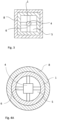
- Fig. 4A to C show different embodiments of the elongated center element 4.
- Fig 4A shows an example of an elongated center element 4 having a square cross-section.
- the quadratic cross-section gives rise to a screw-shaped longitudinal surface profile, as shown in Fig. 5 .
- Fig. 4B shows an example of an elongated center element 4 having a circular cross-section.
- Fig. 4C shows an example of an elongated center element 4 being a hollow bar. The hollow will provide for a larger surface for heating the flow of gas, or the hollow will allow for the insertion of a thermocouple for measuring and/or controlling the temperature.
- the flow of gas passing through the channel 5 will be affected by the longitudinal surface profile of the elongated center element 4, causing turbulence in the channel 5 along the surface as shown by the arrows.
- the turbulence results in a more efficient heat transfer from the elongated center element 4 and from the outer tube 1 to the flow of gas.
- the present disclosure also provides an electric gas heating system comprising at least two electric gas heater devices 10 according to the present disclosure.
- Fig. 6 illustrates such a system comprising three stacked electric gas heater devices 10.
- the electric gas heater devices 10 are electrically connected to each other in parallel, via electric connection elements 7, to the electric power source 12, and are separated from each other by an intermediate channel 15.
- the electric gas heater devices 10 may be stacked next to each other in a planar configuration, or both next to each other and on top of each other in a volumetric configuration.
- the intermediate channel 15 between the electric gas heater devices 10 may constitute a secondary gas channel, through which the gas may flow to be heated by adjacent outer tubes 1.
- the intermediate channel 15 has a cross-section delimited by outer peripheries of adjacent tubes 1. Rectangular or hexagonal cross-sections of the outer tubes 1 promote close stacking of the electric gas heater devices 10 such that a volume-efficient system is provided.
- the intermediate channel 15 contains the electrically insulating insulation member 8, which may comprise a porous ceramic fiber material.
- the insulation member may also be heat insulating.
- the electric gas heater devices 10 of the electric gas heating system may be structurally connected by a connecting element 13.
- the connecting element 13 may be a plate to hold the electric gas heater devices 10 in a furnace.
- the connecting element 13 is configured to allow gas to pass.
- the connecting element 13 may for instance be perforated.
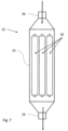
- Fig. 7 shows a conceptual example of an electrical gas heating system comprising multiple electric gas heater devices 10 arranged in a casing 22.
- the example shows three electric gas heater devices in the casing 22, but the number of gas heater devices 10 may be selected as deemed appropriate, depending on conditions and applications.
- the casing comprises a body 23 housing the electric gas heater devices 10, a gas outlet 24 at an inlet end and a gas inlet 26 at an opposite outlet end.
- the gas flows through the gas outlet 24, via the electric gas heater devices 10, and subsequently leaves the casing through the gas inlet 26.
- the flow of gas is indicated by arrows. Electrical and mechanical connections between the electric gas heater devices 10 are not shown in Fig. 7 for the sake of clarity.
- the electric gas heater devices 10 may be arranged in various spacial configurations in relation to each other and in relation to the casing 22 to achieve a predetermined heating effect, as discussed above.
- the casing 22 may also be designed in various shapes, depending on the intended application.
- the gas inlet 26 may for instance be shaped to direct the flow of gas from a source into the casing 22 in a particular manner.
- the gas outlet 24 may be shaped to direct a flow of heated gas leaving the casing 22, towards an object to be heated.
- the body 23 of the casing 22 may for instance have a tubular, a rectangular or a hexagonal cross-section.
- the casing also allows the gas to be pressurized to increase the heat capacity of the gas, which in turn results in a more efficient heat transfer from the electric gas heating system to the gas.
Landscapes
- Engineering & Computer Science (AREA)
- Physics & Mathematics (AREA)
- Thermal Sciences (AREA)
- Chemical & Material Sciences (AREA)
- Combustion & Propulsion (AREA)
- Mechanical Engineering (AREA)
- General Engineering & Computer Science (AREA)
- Resistance Heating (AREA)
Description
- The present disclosure relates to an electric gas heater device, and in particular to a gas heater device providing efficient heating of a gas channel.
- There exists a need for hot gases in industry, e.g. for heating different objects. These hot gases are usually generated by burning fossil fuels, however there is nowadays a desire to replace fossil fuels with fossil-free energy, but it is technically challenging.
- It is possible to heat gases by using one or more resistive elements. The elements used must have a large surface area in order to provide an efficient convective heat transfer to the gas. The heat transfer efficiency will depend on the temperature difference between the surface of the element and the gas to be heated and there is always a limit to how hot the heating element can become before failure. The heat transfer to the gas will deteriorate as the gas temperature is approaching the maximum element temperature. The density and viscosity of gas to be heated also tend to change with increasing temperature which means that efficient convective heat transfer becomes more difficult.
- Another proposed method for electrically heating a gas is to conduct the gas through at least one tube that is resistively heated by connecting both ends of the tube to an electrical power source. One problem with such a solution is that the heat transfer area will be limited to the inner surface area of the tube. A large length of the pipe will therefore be required in order to heat the gas passing through it to a high temperature. Yet another problem is that there will be electromagnetically forces between parallel tubes in a larger assembly. These forces may cause problems such as bending and dislocation of the tubes and may cause tube-to-tube contacts and short circuits.
- A known electric gas heater device is disclosed in
US 2011/309068 A1 and comprises the features indicated in the preamble ofclaim 1. - The present invention aims at solving or at least reducing the above mentioned problems.
- The present disclosure therefore provides an electric gas heater device, comprising:
- an outer tube of an electrically conducting material having a gas inlet in a first end and a gas outlet in a second end which is opposite to the first end,
- an elongated center element of an electrically conducting material arranged inside said outer tube, wherein the outer tube and the elongated center element form a channel between them, in which a flow of gas will be heated, said channel having a cross-section defined by an inner periphery of the outer tube and an outer periphery of the elongated center element,
- The outer tube is an active component as it acts as an electric resistance heating element connected in series with the elongated center element which will also be acting as an electric resistance heating element. Thus, heat will be transferred from both the outer tube and from the elongated center element to the flow of gas. A greater heat transfer area per unit of volume is thereby achieved as compared to prior art, which means that a more efficient heat transfer from heating element to gas is achieved.
- According to one embodiment, the first end of the outer tube and the elongated center element define a gas inlet end into said channel, and the second end of the outer tube and the elongated center element define a gas outlet end from said channel. As the gas enter the first end and exit the second end, the first end may also be called the cold end and the second end may also be called the hot end.
- According to another embodiment, the outer tube and the elongated center element have different length, i.e. either will the outer tube be longer in a longitudinal direction than the elongated center element or the elongated center element will be longer in a longitudinal direction than the outer tube.
- According to one embodiment, the outer tube and the elongated center element define an electric circuit in which they are connected in series when connected to an electric power source through said one or more electric connection elements.
- According to one embodiment, the elongated center element is a rod extending in a longitudinal direction of the outer tube. According to another embodiment, the elongated center element is a circular rod. According to yet another embodiment, the elongated center element is a hollow bar. According to another embodiment, the elongated center element has a surface profile along a longitudinal length of the elongated center element, which surface profile may increase the turbulence of gas when passing through the channel. According to yet another embodiment, the surface profile is a threaded, screw-shaped, undulating or spiral-shaped along the longitudinal length of the elongated center element.
- According to one embodiment, the rod is coaxial with the outer tube.
- According to one embodiment, distance elements, arranged in said channel, will support the elongated center element radially with regard to the outer tube. The distance elements may be made of an electrically insulating material, such as a dielectric material. According to one embodiment, the distance elements comprise or consist of ceramic material or ceramic bodies. The distance elements may have any shape as long as the shape does not have a negative impact on the gas flow. Examples of shapes are a rod, a pin or e a blade. If the distance elements are shaped as blades they may be arranged so as to increase the turbulence of the flow of gas passing through the channel from the first end to the second end, and thereby improving the heat transfer to the flow of gas. At least some of the distance elements should be located closer to the first end than to the second end.
- According to one embodiment, the electric connection between the outer tube and the elongated center element may comprise one or more interconnects, also called struts, which may be positioned at either the first or the second end, and are arranged to support the elongated center element radially with regard to the outer tube. The one or more electric connection element will always be placed on the opposite end of the one or more interconnects. The one or more interconnects will electrically connect the outer tube to the elongated center element. Additionally, the one or more interconnects will ensure that the elongated center element is centered within the outer tube and may also guide the flow of gas. As electrical current is going through the one or more interconnects, heat may also be generated which may be transferred to the flow of gas as it passes the one or more interconnects.
- According to one embodiment, at least one of the outer tube or the elongated center element is a resistance heating element comprising or consisting of an iron-chromium-aluminium alloy (FeCrAl-alloy) which comprises at least 2 weight% aluminium.
- According to one embodiment, both the outer tube and the elongated center element are resistance heating elements comprising or consisting of a FeCrAl-alloy.
- According to one embodiment, the electric gas heater device further comprises an electrically insulating insulation member. The electrically insulating insulation member may also be heat insulating and arranged on an outer periphery of the outer tube. Loss of heat to the environment through radiation is thereby suppressed and additionally the risk of having short circuits with surrounding structures is also reduced. The insulation may comprise a body composed of ceramic fibers.
- According to one embodiment, a thermocouple may be mounted in the elongated center element. The thermocouple is used for measuring the temperature of the elongated center element. The electric gas heater device may comprise a control unit for controlling the electric power delivered to the circuit formed by the outer tube and the elongated center element, and the control unit may be arranged so as to receive input from the thermocouple and to control the electric power on a basis thereof.
- According to one embodiment, the outer tube has a cylindrical (circular), rectangular or hexagonal cross-section. According to one embodiment, the electric gas heater device forms part of a gas heating system comprising two or more electric gas heater devices as defined hereinabove or hereinafter, wherein the electric gas heater devices may for example extend alongside each other or may be stacked. Especially a rectangular or hexagonal outer cross-section of the outer tube will improve close stacking of the electric gas heater devices.
- The present disclosure also relates to an electric gas heating system comprising at least two electric gas heater devices as defined hereinabove or hereinafter, wherein the at least two electric gas heater devices are electrically connected to each other in parallel, in series, or in a combination of parallel and series connections and are separated from each other by an intermediate channel. Thereby, the system of electric gas heater devices will provide an even more efficient heating area to unit-volume ratio. According to one embodiment, the electric gas heating system may be enclosed, in e.g. sheath, a casing or an additional outer tube or other suitable vessel, in order to protect the at least two gas heater devices.
- The connection of the electric gas heater devices in parallel, in series, or in a combination of parallel and series connections may be configured depending on the available voltage and current source, in order to adapt the applied voltage and current to the electric gas heating system as defined hereinabove or hereinafter. For instance, if a high-voltage source is available, it may be preferred to divide the applied voltage over the at least two electric gas heater devices by connecting them in series.
- According to one embodiment the intermediate channel constitutes a secondary gas channel.
- According to another embodiment the intermediate channel contains an electrically insulating insulation member. The electrically insulating insulation member may also be heat insulating. The insulating insulation member will reduce heat losses. The present disclosure also relates to an arrangement comprising at least two of the hereinabove or hereinafter defined electric gas heating systems. This arrangement may be covered by a sheath, or casing or an outer tube or a pressurized vessel.
- According to one embodiment, the elongated center elements in an electric gas heating system comprising parallel electrical gas heater devices wherein the elongated center elements will be longer than the outer tubes in the longitudinal direction. Connection means will then be positioned on the part of the elongated center element which is outside the outer tubes and this will provide for the possibility to arrange connection means of the outer tubes and of elongated center elements in two different planes, meaning that the outer tubes are electrically connected by connection means in one plane and the elongated center elements are electrically connected by connection means in another plane. Thereby providing more available space in each plane to arrange desirable connections between the individual gas electrical gas heater devices within the electric gas heating system of electric gas heater devices.
- According to one embodiment of the present disclosure, the one or more electrical connections are placed at the first end of the electric gas heater device (cold end). This may facilitate the ability to unplug and remove one or more non-functioning electric gas heater devices or electric gas heating system and install new of the same.
- Further features and advantages of the electric gas heater device according to the present disclosure will be presented in the following detailed description of an embodiment.
- Embodiments of the electric gas heater device according to the present disclosure will be presented with reference to the annexed drawings, of which
-
Fig. 1 is a cross-section of an electricgas heater device 10 according to the present disclosure, -
Fig. 2 is a cross-section corresponding to that ofFig. 1 , showing a second embodiment of the electricgas heater device 10, and -
Fig. 3 is a cross-section according to I-I inFig. 1 . -
Fig. 4A to C are a cross section of different embodiments of the elongated center element according to the present disclosure. -
Fig. 5 is a perspective view of a surface profile of an elongated center element of the present disclosure. -
Fig. 6 is a schematic presentation of a system of multiple electric gas heaters according to the present disclosure. -
Fig. 7 is a conceptual view of a system of multiple electric gas heaters arranged in a casing according to the present disclosure. -
Fig. 1 shows an electricgas heater device 10 comprising anouter tube 1 of an electrically conducting material having a gas inlet in afirst end 2 and a gas outlet in asecond end 3, which is opposite to thefirst end 2. The electricgas heater device 10 may be part of an arrangement, which comprises a gas source (not shown) provided to conduct a flow of gas to the gas inlet. The gas outlet may be connected to additional piping for further conduction of flow of gas which has been heated by the electric gas heater or for transporting the flow of gas to a nozzle or the like, via which the flow of gas is introduced into a process of any kind, such as a chemical process or a physical process, typically heating. - The electric
gas heater device 10 further comprises anelongated center element 4 of an electrically conducting material arranged inside saidouter tube 1. Theouter tube 1 andelongated center element 4 form achannel 5 between them. Thechannel 5 has a cross-section defined by an inner periphery of theouter tube 1 and an outer periphery of theelongated center element 4. Theelongated center element 4 may be formed by a rod, which is coaxial with the outer tube. - In
Fig. 1 , theouter tube 1 is electrically connected by means of one ormore interconnects 11 to theelongated center element 4 in saidsecond end 3. The one ormore interconnects 11 may be arranged to support the elongated center element radially with regard to the outer tube. In the oppositefirst end 2 theouter tube 1 and theelongated center element 4 are provided with one or moreelectric connection elements 7 for connection thereof to anelectric power source 12. -
Fig. 2 shows an embodiment with the opposite arrangement in the sense that theouter tube 1 is electrically connected by means ofinterconnects 11 to theelongated center element 4 in saidfirst end 2, and theouter tube 1 and theelongated center element 4 are provided with one or moreelectric connection elements 7 for connection thereof to anelectric power source 12 in the oppositesecond end 3. - In both
Fig. 1 and Fig. 2 , thecenter element 4 is connected in series with theouter tube 1. Further, the one or moreelectric connection elements 7 may be positioned on either thefirst end 2 or thesecond end 3 and the one or more electric connection elements will be provided at the opposite end. - The
outer tube 1 comprises or consist of a FeCrAl alloy and will thereby act as a resistive heating element. Theelongated center element 4 also comprises or consists of a FeCrAl alloy and will thereby also act as a resistive heating element. A cross-sectional area of theelongated center element 4 is chosen in relation to a cross-sectional area of theouter tube 1 so as to balance the electric resistivity of the elongated center element and of the outer tube in order to obtain the required heating characteristics of the electricgas heater device 10. Since it is preferred to keep the temperature of theouter tube 1 and of thecenter element 4 as low as possible, the respective cross-sectional areas are calculated so that the surface loads of the outer surface of thecenter element 4 and of the inner surface of theouter tube 1 are generally equal during operation of the electricgas heater device 10. - Because the
center element 4 and theouter tube 1 are connected in series, a direction of current through thecenter element 4 will be opposite to a direction of current through theouter tube 1. Consequently, the coaxial configuration of thecenter element 4 in relation to theouter tube 1 will cause the magnetic fields, generated by the current passing through thecenter element 4 and theouter tube 1 respectively, to cancel each other. - On the inner periphery of the
outer tube 1, an oxide layer (Al2O3) will be obtained as this will be formed due to the FeCrAl alloy. On the outer periphery of theelongated center element 4, an Al2O3 layer will also be formed. - The
elongated center element 4 is held in position radially with regard to theouter tube 1 bydistance elements 6 arranged in said channel. Thedistance elements 6 may be composed of ceramic and may be shaped as blades having surfaces which are inclined with regard to the longitudinal direction, designed so as to increase the turbulence of a gas passing through thechannel 5 from thefirst end 2 to thesecond end 3. In the embodiment shown inFig. 1 , thedistance elements 6 are closer to thefirst end 2 than to thesecond end 3. Thedistance elements 6 may also be shaped as a pin or a rod. The form of thedistance element 6 should have as little as possible negative impact on the flow of gas. - An electrically insulating
insulation member 8 is arranged on an outer periphery of theouter tube 1. Theinsulation member 8 comprises a cylindric body composed of ceramic fiber material, e.g. a porous ceramic fiber material. The insulation member may also be heat insulating. - A thermocouple 9 may be mounted in an end of the
elongated center element 4 for the purposed of detecting the temperature of theelongated center element 4. The thermocouple may alternatively be mounted on an end of an outside surface of theouter tube 1. The electricgas heater device 10 may comprise a control unit (not shown) for controlling the electric power delivered to the circuit formed by theouter tube 1 and theelongated center element 4. The control unit may be arranged so as to receive input from the thermocouple 9 and to control the electric power to the electricgas heater device 10 on basis thereof. -
Fig. 3 shows an embodiment according to which theouter tube 1 has rectangular or hexagonal cross-section, promoting close stacking of two or more electricgas heater devices 10 alongside each other. - In one embodiment, the
elongated center element 4, e.g. the rod, is provided with a cross-sectional shape so as to promote turbulence along a longitudinal length of theelongated center element 4. For this purpose, the cross-sectional shape may be polygonal, such as triangular, square or rectangular. Theelongated center element 4 may further be twisted around its longitudinal axis such that the cross-sectional shape forms a surface profile along the longitudinal length of theelongated center element 4. The surface profile may thus be threaded, screw-shaped, undulating or spiral-shaped along the longitudinal length of theelongated center element 4.Fig. 4A to C show different embodiments of theelongated center element 4.Fig 4A shows an example of anelongated center element 4 having a square cross-section. When theelongated center element 4 having a square cross-section is twisted, during manufacturing, the quadratic cross-section gives rise to a screw-shaped longitudinal surface profile, as shown inFig. 5 .Fig. 4B shows an example of anelongated center element 4 having a circular cross-section.Fig. 4C shows an example of anelongated center element 4 being a hollow bar. The hollow will provide for a larger surface for heating the flow of gas, or the hollow will allow for the insertion of a thermocouple for measuring and/or controlling the temperature. The flow of gas passing through thechannel 5 will be affected by the longitudinal surface profile of theelongated center element 4, causing turbulence in thechannel 5 along the surface as shown by the arrows. The turbulence results in a more efficient heat transfer from theelongated center element 4 and from theouter tube 1 to the flow of gas. - The present disclosure also provides an electric gas heating system comprising at least two electric
gas heater devices 10 according to the present disclosure.Fig. 6 illustrates such a system comprising three stacked electricgas heater devices 10. The electricgas heater devices 10 are electrically connected to each other in parallel, viaelectric connection elements 7, to theelectric power source 12, and are separated from each other by anintermediate channel 15. Depending on the space and application where the electric gas heating system is to be installed, the electricgas heater devices 10 may be stacked next to each other in a planar configuration, or both next to each other and on top of each other in a volumetric configuration. - The
intermediate channel 15 between the electricgas heater devices 10 may constitute a secondary gas channel, through which the gas may flow to be heated by adjacentouter tubes 1. Theintermediate channel 15 has a cross-section delimited by outer peripheries ofadjacent tubes 1. Rectangular or hexagonal cross-sections of theouter tubes 1 promote close stacking of the electricgas heater devices 10 such that a volume-efficient system is provided. - In one embodiment, the
intermediate channel 15 contains the electrically insulatinginsulation member 8, which may comprise a porous ceramic fiber material. The insulation member may also be heat insulating. - The electric
gas heater devices 10 of the electric gas heating system may be structurally connected by a connectingelement 13. The connectingelement 13 may be a plate to hold the electricgas heater devices 10 in a furnace. When theintermediate channel 15 is used as a secondary gas channel, the connectingelement 13 is configured to allow gas to pass. The connectingelement 13 may for instance be perforated. -
Fig. 7 shows a conceptual example of an electrical gas heating system comprising multiple electricgas heater devices 10 arranged in acasing 22. The example shows three electric gas heater devices in thecasing 22, but the number ofgas heater devices 10 may be selected as deemed appropriate, depending on conditions and applications. The casing comprises abody 23 housing the electricgas heater devices 10, agas outlet 24 at an inlet end and agas inlet 26 at an opposite outlet end. The gas flows through thegas outlet 24, via the electricgas heater devices 10, and subsequently leaves the casing through thegas inlet 26. The flow of gas is indicated by arrows. Electrical and mechanical connections between the electricgas heater devices 10 are not shown inFig. 7 for the sake of clarity. - The electric
gas heater devices 10 may be arranged in various spacial configurations in relation to each other and in relation to thecasing 22 to achieve a predetermined heating effect, as discussed above. Thecasing 22 may also be designed in various shapes, depending on the intended application. Thegas inlet 26 may for instance be shaped to direct the flow of gas from a source into thecasing 22 in a particular manner. Further, thegas outlet 24 may be shaped to direct a flow of heated gas leaving thecasing 22, towards an object to be heated. Thebody 23 of thecasing 22 may for instance have a tubular, a rectangular or a hexagonal cross-section. - The casing also allows the gas to be pressurized to increase the heat capacity of the gas, which in turn results in a more efficient heat transfer from the electric gas heating system to the gas.
-
- 1.
- Outer tube
- 2.
- First end
- 3.
- Second end
- 4.
- Elongated center element
- 5.
- Channel
- 6.
- Distance elements
- 7.
- One or more electric connection elements
- 8.
- Electrically insulating and heat insulating insulation element
- 9.
- Thermocouple
- 10.
- Electric gas heater device
- 11.
- One or more interconnects
- 12.
- Electric power source
- 13.
- Connecting element
- 15.
- Intermediate channel
- 22
- Casing
- 23
- Body of the casing
- 24
- Gas outlet
- 26
- Gas inlet
Claims (15)
- An electric gas heater device (10), comprising:- an outer tube (1) of an electrically conducting material having a gas inlet in a first end (2) and a gas outlet in second end (3) which is opposite to the first end (2),- an elongated center element (4) of an electrically conducting material arranged inside said outer tube (1),wherein the outer tube (1) and the elongated center element (4) form a channel (5) between them, said channel (5) having a cross-section defined by an inner periphery of the outer tube (1) and an outer periphery of the elongated center element (4),wherein the outer tube (1) is electrically connected by means of one or more interconnect (11) to the elongated center element (4) in one of the first or second ends, and in the other of said first or second ends, the outer tube (1) and the elongated center element (4) are provided with one or more electric connection elements (7) for connection thereof to an electric power source.
- The electric gas heater device (10) according to claim 1, wherein the outer tube (1) and the elongated center element (4) define an electric circuit in which they are connected in series when connected to an electric power source (12) through said one or more electric connection elements (7).
- The electric gas heater device (10) according to claim 1 or 2, wherein the elongated center element (4) is a rod extending in a longitudinal direction of the outer tube (1).
- The electric gas heater device (10) according to any of the previous claims, wherein the elongated center element (4) has surface profile along a longitudinal length of the elongated center element (4), which increases the turbulence of a gas passing through the channel.
- The electric gas heater device (10) according to claim 4, wherein the surface profile is a threaded, screw-shaped, undulating or spiral-shaped along the longitudinal length of the elongated center element (4).
- The electric gas heater device (10) according to any one of claims 3 to 4, wherein the rod is coaxial with the outer tube (1).
- The electric gas heater device (10) according to any one of claims 1 to 6, wherein distance elements (6), arranged in said channel (5), support the elongated center element (4) radially with regard to the outer tube (1).
- The electric gas heater device (10) according to any one of claims 1 to 7, wherein at least one of the outer tubes (1) or the elongated center element (4) is a resistance heating element comprising or consisting of a FeCrAl-alloy.
- The electric gas heater device (10) according to any one of claims 1 to 8, wherein the outer tube (1) and the elongated center element (4) are resistance heating elements comprising a FeCrAl-alloy.
- The electric gas heater device (10) according to any one of claims 1 to 9, further comprising an electrically insulating member (8) arranged on an outer periphery of the outer tube (1).
- The electric gas heater device (10) according to claim 10, wherein a thermocouple (9) is mounted in the elongated center element (4).
- The electric gas heater device (10) according to any one of claims 1 to 11, wherein the outer tube (1) has a rectangular or a hexagonal or a cylindrical cross-section.
- An electric gas heating system comprising at least two electric gas heater devices (10) according to any of the claims 1- 12, wherein the at least two electric gas heater devices (10) are electrically connected to each other in parallel, in series, or in a combination of parallel and series connections and are separated from each other by an intermediate channel (15) having a cross-section delimited by outer peripheries of adjacent tubes (1).
- The electric gas heating system according to claim 13, wherein the intermediate channel (15) constitutes a secondary gas channel.
- The electric gas heating system according to claim 13, wherein the intermediate channel (15) contains an electrically insulating insulation member (8).
Applications Claiming Priority (2)
| Application Number | Priority Date | Filing Date | Title |
|---|---|---|---|
| SE1900157 | 2019-10-01 | ||
| PCT/SE2020/000024 WO2021107832A1 (en) | 2019-10-01 | 2020-10-01 | An electric gas heater device and a system of electric gas heater devices |
Publications (4)
| Publication Number | Publication Date |
|---|---|
| EP4038324A1 EP4038324A1 (en) | 2022-08-10 |
| EP4038324A4 EP4038324A4 (en) | 2023-10-25 |
| EP4038324C0 EP4038324C0 (en) | 2025-01-29 |
| EP4038324B1 true EP4038324B1 (en) | 2025-01-29 |
Family
ID=76130713
Family Applications (1)
| Application Number | Title | Priority Date | Filing Date |
|---|---|---|---|
| EP20893211.1A Active EP4038324B1 (en) | 2019-10-01 | 2020-10-01 | An electric gas heater device and a system of electric gas heater devices |
Country Status (2)
| Country | Link |
|---|---|
| EP (1) | EP4038324B1 (en) |
| WO (1) | WO2021107832A1 (en) |
Families Citing this family (1)
| Publication number | Priority date | Publication date | Assignee | Title |
|---|---|---|---|---|
| CN116287519B (en) * | 2023-02-15 | 2024-08-27 | 钢研晟华科技股份有限公司 | High-temperature hydrogen electric heating device and method for pure hydrogen shaft furnace reduction |
Family Cites Families (8)
| Publication number | Priority date | Publication date | Assignee | Title |
|---|---|---|---|---|
| GB980454A (en) * | 1960-12-14 | 1965-01-13 | Ass Elect Ind | Improvements in or relating to electrical resistance heaters |
| JPS5991683A (en) * | 1982-11-16 | 1984-05-26 | 松下電工株式会社 | Heat generator |
| DE19610593A1 (en) * | 1996-03-18 | 1997-09-25 | Wastec Ag | Heat exchanger for immersion heater |
| US8119954B2 (en) * | 2003-01-07 | 2012-02-21 | Micropyretics Heaters International, Inc. | Convective heating system for industrial applications |
| EP1814362A1 (en) * | 2006-01-30 | 2007-08-01 | Leister Process Technologies | Heating element for a hot air device |
| EP2354704A1 (en) * | 2009-12-30 | 2011-08-10 | Rauschert Steinbach GmbH | Heating device for generating extremely hot gases |
| WO2014107132A1 (en) * | 2013-01-02 | 2014-07-10 | Swerea Mefos Ab | Pressure vessel and method of heating a gas in a pressurised pipe |
| DE102014102474A1 (en) * | 2014-02-25 | 2015-08-27 | Sandvik Materials Technology Deutschland Gmbh | Heating element and process heater |
-
2020
- 2020-10-01 WO PCT/SE2020/000024 patent/WO2021107832A1/en not_active Ceased
- 2020-10-01 EP EP20893211.1A patent/EP4038324B1/en active Active
Also Published As
| Publication number | Publication date |
|---|---|
| EP4038324A1 (en) | 2022-08-10 |
| EP4038324A4 (en) | 2023-10-25 |
| EP4038324C0 (en) | 2025-01-29 |
| WO2021107832A1 (en) | 2021-06-03 |
Similar Documents
| Publication | Publication Date | Title |
|---|---|---|
| US11102848B2 (en) | Variable pitch resistance coil heater | |
| US9345070B2 (en) | Variable pitch resistance coil heater | |
| US12281819B2 (en) | Electric fluid flow heater with heating elements stabilization fins | |
| RU2669589C1 (en) | Heating element and process heater | |
| EP3721150B1 (en) | Electric fluid flow heater with heating element support member | |
| KR102600216B1 (en) | Electric fluid flow heater with stabilizing brace | |
| US12615698B2 (en) | Heating element | |
| WO2021107832A1 (en) | An electric gas heater device and a system of electric gas heater devices | |
| TWI876174B (en) | Electric heater system | |
| KR102932848B1 (en) | Process Flange Heater Standoff Assembly | |
| TWI679921B (en) | Variable pitch resistance coil heater | |
| CN224266617U (en) | Continuous spiral baffle heat exchanger | |
| US20230059671A1 (en) | Continuous helical baffle heat exchanger | |
| WO2025175137A1 (en) | High temperature heat exchanger with removable heater bundles | |
| KR20240165364A (en) | Heating elements and fluid heaters and methods for heating fluids | |
| WO2025207004A1 (en) | Fluid guiding module fluid heater and fluid heating apparatus | |
| GB2573742A (en) | A heating element |
Legal Events
| Date | Code | Title | Description |
|---|---|---|---|
| STAA | Information on the status of an ep patent application or granted ep patent |
Free format text: STATUS: THE INTERNATIONAL PUBLICATION HAS BEEN MADE |
|
| PUAI | Public reference made under article 153(3) epc to a published international application that has entered the european phase |
Free format text: ORIGINAL CODE: 0009012 |
|
| STAA | Information on the status of an ep patent application or granted ep patent |
Free format text: STATUS: REQUEST FOR EXAMINATION WAS MADE |
|
| 17P | Request for examination filed |
Effective date: 20220502 |
|
| AK | Designated contracting states |
Kind code of ref document: A1 Designated state(s): AL AT BE BG CH CY CZ DE DK EE ES FI FR GB GR HR HU IE IS IT LI LT LU LV MC MK MT NL NO PL PT RO RS SE SI SK SM TR |
|
| DAV | Request for validation of the european patent (deleted) | ||
| DAX | Request for extension of the european patent (deleted) | ||
| REG | Reference to a national code |
Ref country code: DE Ref legal event code: R079 Free format text: PREVIOUS MAIN CLASS: F24H0003040000 Ipc: H05B0003420000 Ref country code: DE Ref legal event code: R079 Ref document number: 602020045646 Country of ref document: DE Free format text: PREVIOUS MAIN CLASS: F24H0003040000 Ipc: H05B0003420000 |
|
| A4 | Supplementary search report drawn up and despatched |
Effective date: 20230927 |
|
| RIC1 | Information provided on ipc code assigned before grant |
Ipc: F24H 9/20 20220101ALI20230921BHEP Ipc: F24H 9/1863 20220101ALI20230921BHEP Ipc: F24H 9/00 20220101ALI20230921BHEP Ipc: F24H 3/04 20220101ALI20230921BHEP Ipc: H05B 3/42 20060101AFI20230921BHEP |
|
| GRAP | Despatch of communication of intention to grant a patent |
Free format text: ORIGINAL CODE: EPIDOSNIGR1 |
|
| STAA | Information on the status of an ep patent application or granted ep patent |
Free format text: STATUS: GRANT OF PATENT IS INTENDED |
|
| RIC1 | Information provided on ipc code assigned before grant |
Ipc: F24H 9/20 20220101ALI20240807BHEP Ipc: F24H 9/1863 20220101ALI20240807BHEP Ipc: F24H 9/00 20220101ALI20240807BHEP Ipc: F24H 3/04 20220101ALI20240807BHEP Ipc: H05B 3/42 20060101AFI20240807BHEP |
|
| INTG | Intention to grant announced |
Effective date: 20240819 |
|
| GRAS | Grant fee paid |
Free format text: ORIGINAL CODE: EPIDOSNIGR3 |
|
| GRAA | (expected) grant |
Free format text: ORIGINAL CODE: 0009210 |
|
| STAA | Information on the status of an ep patent application or granted ep patent |
Free format text: STATUS: THE PATENT HAS BEEN GRANTED |
|
| AK | Designated contracting states |
Kind code of ref document: B1 Designated state(s): AL AT BE BG CH CY CZ DE DK EE ES FI FR GB GR HR HU IE IS IT LI LT LU LV MC MK MT NL NO PL PT RO RS SE SI SK SM TR |
|
| REG | Reference to a national code |
Ref country code: GB Ref legal event code: FG4D |
|
| REG | Reference to a national code |
Ref country code: CH Ref legal event code: EP |
|
| REG | Reference to a national code |
Ref country code: DE Ref legal event code: R096 Ref document number: 602020045646 Country of ref document: DE |
|
| REG | Reference to a national code |
Ref country code: IE Ref legal event code: FG4D |
|
| U01 | Request for unitary effect filed |
Effective date: 20250204 |
|
| U07 | Unitary effect registered |
Designated state(s): AT BE BG DE DK EE FI FR IT LT LU LV MT NL PT RO SE SI Effective date: 20250210 |
|
| PG25 | Lapsed in a contracting state [announced via postgrant information from national office to epo] |
Ref country code: RS Free format text: LAPSE BECAUSE OF FAILURE TO SUBMIT A TRANSLATION OF THE DESCRIPTION OR TO PAY THE FEE WITHIN THE PRESCRIBED TIME-LIMIT Effective date: 20250429 |
|
| PG25 | Lapsed in a contracting state [announced via postgrant information from national office to epo] |
Ref country code: PL Free format text: LAPSE BECAUSE OF FAILURE TO SUBMIT A TRANSLATION OF THE DESCRIPTION OR TO PAY THE FEE WITHIN THE PRESCRIBED TIME-LIMIT Effective date: 20250129 |
|
| PG25 | Lapsed in a contracting state [announced via postgrant information from national office to epo] |
Ref country code: ES Free format text: LAPSE BECAUSE OF FAILURE TO SUBMIT A TRANSLATION OF THE DESCRIPTION OR TO PAY THE FEE WITHIN THE PRESCRIBED TIME-LIMIT Effective date: 20250129 |
|
| PG25 | Lapsed in a contracting state [announced via postgrant information from national office to epo] |
Ref country code: IS Free format text: LAPSE BECAUSE OF FAILURE TO SUBMIT A TRANSLATION OF THE DESCRIPTION OR TO PAY THE FEE WITHIN THE PRESCRIBED TIME-LIMIT Effective date: 20250529 Ref country code: NO Free format text: LAPSE BECAUSE OF FAILURE TO SUBMIT A TRANSLATION OF THE DESCRIPTION OR TO PAY THE FEE WITHIN THE PRESCRIBED TIME-LIMIT Effective date: 20250429 |
|
| PG25 | Lapsed in a contracting state [announced via postgrant information from national office to epo] |
Ref country code: HR Free format text: LAPSE BECAUSE OF FAILURE TO SUBMIT A TRANSLATION OF THE DESCRIPTION OR TO PAY THE FEE WITHIN THE PRESCRIBED TIME-LIMIT Effective date: 20250129 |
|
| PG25 | Lapsed in a contracting state [announced via postgrant information from national office to epo] |
Ref country code: GR Free format text: LAPSE BECAUSE OF FAILURE TO SUBMIT A TRANSLATION OF THE DESCRIPTION OR TO PAY THE FEE WITHIN THE PRESCRIBED TIME-LIMIT Effective date: 20250430 |
|
| PG25 | Lapsed in a contracting state [announced via postgrant information from national office to epo] |
Ref country code: SM Free format text: LAPSE BECAUSE OF FAILURE TO SUBMIT A TRANSLATION OF THE DESCRIPTION OR TO PAY THE FEE WITHIN THE PRESCRIBED TIME-LIMIT Effective date: 20250129 |
|
| U20 | Renewal fee for the european patent with unitary effect paid |
Year of fee payment: 6 Effective date: 20250909 |
|
| PGFP | Annual fee paid to national office [announced via postgrant information from national office to epo] |
Ref country code: GB Payment date: 20250904 Year of fee payment: 6 |
|
| PG25 | Lapsed in a contracting state [announced via postgrant information from national office to epo] |
Ref country code: CZ Free format text: LAPSE BECAUSE OF FAILURE TO SUBMIT A TRANSLATION OF THE DESCRIPTION OR TO PAY THE FEE WITHIN THE PRESCRIBED TIME-LIMIT Effective date: 20250129 |
|
| PG25 | Lapsed in a contracting state [announced via postgrant information from national office to epo] |
Ref country code: SK Free format text: LAPSE BECAUSE OF FAILURE TO SUBMIT A TRANSLATION OF THE DESCRIPTION OR TO PAY THE FEE WITHIN THE PRESCRIBED TIME-LIMIT Effective date: 20250129 |
|
| PLBE | No opposition filed within time limit |
Free format text: ORIGINAL CODE: 0009261 |
|
| STAA | Information on the status of an ep patent application or granted ep patent |
Free format text: STATUS: NO OPPOSITION FILED WITHIN TIME LIMIT |
|
| 26N | No opposition filed |
Effective date: 20251030 |