EP4037571B1 - Biopsieanordnungen - Google Patents
Biopsieanordnungen Download PDFInfo
- Publication number
- EP4037571B1 EP4037571B1 EP20781369.2A EP20781369A EP4037571B1 EP 4037571 B1 EP4037571 B1 EP 4037571B1 EP 20781369 A EP20781369 A EP 20781369A EP 4037571 B1 EP4037571 B1 EP 4037571B1
- Authority
- EP
- European Patent Office
- Prior art keywords
- needle
- sheath
- actuator
- connector
- connector part
- Prior art date
- Legal status (The legal status is an assumption and is not a legal conclusion. Google has not performed a legal analysis and makes no representation as to the accuracy of the status listed.)
- Active
Links
Images



Classifications
-
- A—HUMAN NECESSITIES
- A61—MEDICAL OR VETERINARY SCIENCE; HYGIENE
- A61B—DIAGNOSIS; SURGERY; IDENTIFICATION
- A61B10/00—Instruments for taking body samples for diagnostic purposes; Other methods or instruments for diagnosis, e.g. for vaccination diagnosis, sex determination or ovulation-period determination; Throat striking implements
- A61B10/02—Instruments for taking cell samples or for biopsy
- A61B10/0233—Pointed or sharp biopsy instruments
- A61B10/0266—Pointed or sharp biopsy instruments means for severing sample
- A61B10/0275—Pointed or sharp biopsy instruments means for severing sample with sample notch, e.g. on the side of inner stylet
-
- A—HUMAN NECESSITIES
- A61—MEDICAL OR VETERINARY SCIENCE; HYGIENE
- A61B—DIAGNOSIS; SURGERY; IDENTIFICATION
- A61B10/00—Instruments for taking body samples for diagnostic purposes; Other methods or instruments for diagnosis, e.g. for vaccination diagnosis, sex determination or ovulation-period determination; Throat striking implements
- A61B10/02—Instruments for taking cell samples or for biopsy
- A61B2010/0208—Biopsy devices with actuators, e.g. with triggered spring mechanisms
Definitions
- Embodiments herein relate to a biopsy system that comprises an actuator device and a needle arrangement configured to be operatively connected to each other.
- a biopsy sampling arrangement includes, typically, in addition to a needle arrangement also some kind of actuator device that facilitates for an operator to push the biopsy needle into tissue and cut a biopsy sample of tissue.
- Prior art biopsy needles (typically referred as "tru cut” needles") have a drawback in that they collect a large amount of tissue on its way to a target area inside a patient. During insertion, the needle will often encounter areas in which bacteria are present and such bacteria is often transported to areas where they will cause an infection. Such a problem has typically been addressed by the use of antibiotics. However, with the increase of resistance to antibiotics, such a chemical way of addressing the problem has become less efficient and there is a demand for different technical solutions.
- WO03/026509A2 describes a tissue-sampling device that includes a cannula and a stylet formed with at least first and second longitudinally spaced tissue-receiving notches and that is slidably received in the cannula.
- the stylet and cannula are longitudinally movable with respect to each other.
- a trigger-mechanism is operatively coupled to at least the cannula.
- the trigger-mechanism is configured such that, whenever the stylet is in an extended position and the cannula is in a retracted position, activating the trigger-mechanism causes the cannula to move over the first tissue-receiving notch, but not the second tissue-receiving notch, and activating the trigger-mechanism another time causes the cannula to move over the second tissue-receiving notch.
- US2019/209144A1 describes a biopsy device optimized for the sampling of tissues that are resilient and difficult to cut using conventional approaches.
- the biopsy device includes a cutting cannula, an inner member including a toothed rack having a sharpened distal tip configured to be introduced into the body and a sample notch for receiving the at least one severed tissue sample, and a cutting mechanism configured for causing the cutting cannula to be longitudinally displaced in a distal direction from a first position at the proximal end of the sample notch exposing the sample notch, to a second position at the distal end of the sample notch, so as to sever the tissue sample from remaining body tissue at the harvesting site.
- WO2007/074123A1 describes a biopsy needle set with a first needle having a hollow shaft, a holding area and a distal end opposite the holding area.
- the biopsy needle set has a third needle which has a holding area and a distal end opposite the holding area.
- the second needle has a hollow shaft for receiving the third needle, and both needles are arranged to be able to move to and fro relative to one another.
- US2007/208272A1 describes a biopsy device that includes an outer cutting cannula and an inner cannula. The inner cannula has a side sample port for receiving a biopsy sample.
- the outer cannula can be selectively positioned with respect to the side port to provide fine needle aspiration sampling or core biopsy sampling.
- US2011/237976A1 describes a biopsy device assembly that includes a housing and a biopsy device that extends out of the housing and that collects and cuts anatomical tissue from the patient.
- the assembly includes a hemostatic agent removably housed in the biopsy device and an actuator assembly that moves the biopsy device relative to the housing from a first position to an extended position such that the biopsy device collects and cuts the anatomical tissue from the patient.
- the actuator assembly also retracts the biopsy device relative to the housing toward a retracted position.
- an object of the present disclosure is to overcome drawbacks related to prior art biopsy devices.
- the invention is set out in the appended set of claims.
- an actuator device comprises a frame, a first actuator, a second actuator and a third actuator.
- the first, second and third actuators are configured to move in relation to the frame and configured to be operatively connected to the biopsy needle arrangement.
- the biopsy needle arrangement comprises a needle sheath and a needle.
- the needle sheath has a proximal end and a distal end and the needle sheath constitutes an elongated tube having a sheath opening at the distal end of the needle sheath.
- the needle has a proximal end and a distal end and a length that is greater than the length of the needle sheath.
- the needle comprises an elongated shaft portion configured to fit inside and slide relative to the needle sheath, and a tip portion connected to the shaft portion and located at the distal end of the needle.
- the tip portion has a transverse extension, or width, that is greater than a transverse extension, or width, of the sheath opening.
- the biopsy needle arrangement has a closed state and an open state, the tip portion abutting the needle sheath in the closed state, and the tip portion extending from the distal end of the needle sheath in the open state.
- the first actuator is configured to be operatively connected to the needle and configured to, with the needle arrangement in its closed state, push the needle distally in a sliding direction relative to the needle sheath a first distance, d1, at which the needle arrangement is in its open state.
- the second actuator is configured to be operatively connected to the needle sheath and configured to, with the needle arrangement in its open state, push the needle sheath distally in the sliding direction relative to the needle a second distance, d2.
- the third actuator is configured to be operatively connected to the needle sheath and configured to, with the needle arrangement in its open state, push the needle sheath distally in the sliding direction relative to the needle a third distance, d3, where d3 is smaller than d2, at which the needle arrangement is in its closed state.
- Such a biopsy actuator device differs advantageously from prior art biopsy devices at least in that it is configured to operate in a three-step pushing sequence.
- the three-step pushing sequence is effective in performing the actual biopsy as well as being safe in terms of minimizing the risk of causing damage to the needle tip portion, and thereby risking injury to a patient.
- the actuator device configuration makes it possible, following the step of pushing the needle forward into tissue and the step of pushing the sheath forward (thereby cutting a biopsy sample), to avoid an unwanted collision between the sheath and the needle tip. This is due to the fact that the actuator device pushes the sheath forward a relatively long distance when cutting tissue, the length of this second pushing step being just short of the full distance to close the needle arrangement in the closed state. The remaining short distance is then covered by the sheath when actuated by the third actuator during the third step, and thereby closing the needle arrangement.
- Prior art tru cut needles comprising a needle within a sheath have an open tip.
- the motion of such a needle is mediated by a prior art actuator in two steps where the needle initially is pushed forward and then the sheath is pushed forward, cutting a tissue sample.
- There is no need for exact precision in the movement of the sheath since there is no distal stopping arrangement - the prior art sheath moves freely in relation to the needle. Consequently, using a closed tip biopsy needle arrangement as defined herein together with an actuator device according to prior art, a powerful collision would occur between the needle tip and the sheath, resulting in a significant risk of damaging or even dislodging the needle tip from the needle.
- a damaged or dislodged needle tip inside a patient is an unwanted situation in a biopsy context.
- a common procedure is to perform multiple biopsies (on one and the same patient) using one and the same needle.
- the importance of avoiding damage to the needle is further accentuated because any damage would typically be in the form of edges, lips and cracks that will collect bacteria and thereby increasing the risk of infection.
- the actuators may be configured to bias the needle sheath with respect to the tip portion of the needle for all relative positions between the needle sheath and the tip portion.
- such a configuration of the first and/or second actuator prevents any gap to open between the sheath opening and the tip portion during insertion and retraction of the needle arrangement.
- a bias may be achieved by configuring springs in connection with the actuators as will be exemplified below.
- the tip portion and the sheath may be biased against each other at all times except when they are in action, i.e. at the time when they are actuated (and at a later point in time when the needle arrangement is opened for removal of a tissue sample).
- the force by which the tip portion and the sheath are biased against each other is large enough to keep the tip portion of the needle towards the sheath even when the needle arrangement is pushed and pulled through, e.g., tight fasciae.
- a dynamic force is achieved by the configuration described herein due to the fact that the tip portion and the sheath are biased against each other at all times. It is safer than prior art solutions that lock the tip portion and the sheath against each other, using buttons, levers and hatches etc.
- the configuration described herein overcomes such drawbacks in that a dynamic force is provided, e.g. by the arrangement of springs at the actuators.
- the configuration described herein is simpler than any prior art solution that utilizes a locking mechanism.
- the combination of the design of the needle arrangement and the actuator device enables minimization of bacteria translocation and protects the patient against infection while maintaining adequate diagnostics.
- one and the same biopsy needle arrangement may be used to perform multiple biopsies on the same patient, it is important to minimize any bacteria collection on the needle arrangement between the individual biopsies.
- the first actuator may be configured to be releasably attached to the needle via a needle connector, such a needle connector being configured to disengage the needle from the first actuator when the needle is subjected to a force in the sliding direction, which exceeds a threshold force.
- the second actuator may be configured to be releasably attached to the needle sheath via a sheath connector, such a sheath connector being configured to disengage the needle sheath from the second actuator when the needle sheath is subjected to a force in a direction opposite the sliding direction, which exceeds a threshold force.
- Such needle and/or sheath connectors may be configured such that they comprise two connector parts, one or both of which is attached to or comprised in respective needle and sheath actuator.
- the second actuator may be configured to be attached to a first sheath connector part of the sheath connector, and when the needle sheath disengages from the second actuator, the first sheath connector part disengages from a second sheath connector part attached to the needle sheath and the first sheath connector part moves distally in the sliding direction relative to the second sheath connector part.
- the sheath connector may comprise a first sheath connector part attached to the second actuator and a second sheath connector part configured to be attached to the needle sheath, and when the needle sheath disengages from the second actuator, the first sheath connector part disengages from the second sheath connector part and the first sheath connector part moves distally in the sliding direction relative to the second sheath connector part.
- Such configurations have the advantageous effects of further preventing the needle arrangement from being damaged as a consequence of an unwanted collision between the sheath and the needle tip during the step of pushing the sheath distally as discussed above. That is, if an unwanted collision between the sheath and the needle tip should occur, the result of which is a force upon the needle tip in the distal direction. In case such a force exceeds a threshold force, which may be determined by the specific configuration of the connector parts as will be discussed in more detail below, the first and second connector parts will separate from each other and the connector part that is attached to the needle and/or the sheath will be disconnected from its respective actuator.
- a biopsy needle arrangement comprises a needle sheath and a needle.
- the needle sheath has a proximal end and a distal end and the needle sheath constitutes an elongated tube having a sheath opening at the distal end of the needle sheath.
- the needle has a proximal end and a distal end and a length that is greater than the length of the needle sheath.
- the needle comprises an elongated shaft portion configured to fit inside and slide relative to the needle sheath and a tip portion connected to the shaft portion and located at the distal end of the needle.
- the tip portion has a transverse extension, or width, that is greater than a transverse extension, or width, of the sheath opening.
- the biopsy needle arrangement is configured to be operatively connected to an actuator device that comprises a first actuator and a second actuator, for example an actuator device as summarized above.
- the first actuator is configured to be operatively connected to the needle and configured to push the needle distally in a sliding direction relative to the needle sheath.
- the second actuator is configured to be operatively connected to the needle sheath and configured to push the needle sheath distally in the sliding direction relative to the needle.
- the biopsy needle arrangement further comprises a needle connector configured to attach the needle to the first actuator, and a sheath connector configured to attach the needle sheath to the second actuator.
- the needle connector is configured to disengage the needle from the first actuator when the needle is subjected to a force in the sliding direction, which exceeds a threshold force.
- the sheath connector is configured to disengage the needle sheath from the second actuator when the needle sheath is subjected to a force in a direction opposite the sliding direction, which exceeds a threshold force.
- Such a configuration has the advantageous effects of preventing the needle arrangement from being damaged as a consequence of an unwanted collision between the sheath and the needle tip during the step of pushing the sheath distally as discussed above.
- the sheath connector may comprise a groove that is aligned along at least a first transverse direction relative to the sliding direction. Such a groove is configured to cooperate with a pin of a third actuator of the actuator device, the pin being configured to slide relative to the second actuator in a second transverse direction relative to the sliding direction, the second transverse direction being at an angle a to the first transverse direction.
- Such a configuration further improves the advantage of preventing the needle arrangement from being damaged as a consequence of an unwanted collision between the sheath and the needle tip during the step of pushing the sheath distally as discussed above.
- the needle connector may comprise a first needle connector part configured to be attached to the first actuator, and a second needle connector part attached to the needle, and when the needle disengages from the first actuator, the first needle connector part disengages from the second needle connector part and the second needle connector part moves distally in the sliding direction relative to the first needle connector part.
- the sheath connector may comprise a first sheath connector part configured to be attached to the second actuator, and a second sheath connector part attached to the needle sheath, and when the needle sheath disengages from the second actuator, the first sheath connector part disengages from the second sheath connector part and the first sheath connector part moves distally in the sliding direction relative to the second sheath connector part.
- Such configurations further accentuate the advantageous effects of preventing the needle arrangement from being damaged as a consequence of an unwanted collision between the sheath and the needle tip during the step of pushing the sheath distally as discussed above. That is, if an unwanted collision between the sheath and the needle tip should occur, the result of which is a force upon the needle tip in the distal direction. In case such a force exceeds a threshold force, which may be determined by the specific configuration of the connector parts as will be discussed in more detail below, the first and second connector parts will separate from each other and the connector part that is attached to the needle and/or the sheath will be prevented from moving further in the distal direction.
- a biopsy system comprises an actuator device and a biopsy needle arrangement as summarized above.
- Such a system may be considered as a disposable arrangement. Effects and advantages of such a system correspond to those summarized above in relation to the various configurations of the actuator and the biopsy needle arrangement.
- Figures 1 and 2 illustrate a biopsy system 1 comprising an actuator device 30 and a biopsy needle arrangement 20.
- the actuator device 30 comprises a frame 330, a first actuator 321, a second actuator 322 and a third actuator 323.
- the first, second and third actuators 321, 322, 323 are configured to move in relation to the frame 330 and configured to be operatively connected to the biopsy needle arrangement 20.
- the biopsy needle arrangement 20 comprises a needle sheath 22 and a needle 21.
- the needle sheath 22 has a proximal end 201 and a distal end 202 and the needle sheath 22 constitutes an elongated tube that has a sheath opening 203 at the distal end 202 of the needle sheath 22.
- the needle 21 has a proximal end 211 and a distal end 212 and a length that is greater than the length of the needle sheath 22.
- the needle 21 comprises an elongated shaft portion 213 configured to fit inside and slide relative to the needle sheath 22, and a tip portion 23 connected to the shaft portion 213.
- the tip portion 23 is located at the distal end 212 of the needle 21 and the tip portion 23 has a transverse extension, or width, that is greater than a transverse extension, or width, of the sheath opening 203.
- the transverse extension, or width, of the tip portion 23 may advantageously be equal to the outer transverse extension, or width, of the sheath 22 and thereby making the outer surface smooth and thus minimizing the risk of collecting bacteria during use, as discussed above.
- the illustrated sheath opening 203 and the tip portion 23 define an abutting plane that is perpendicular to the direction x that defines the extension of the needle arrangement 20, other geometries may be configured.
- the sheath opening 203 and the tip portion 23 may define an abutting plane that is at an angle to the direction x that is not a right angle, for example an angle in the interval 20-90 degrees.
- the needle arrangement may be subject of surface treatment and heat coating for the purpose of minimizing transfer of bacteria.
- the biopsy needle arrangement 20 has a closed state and an open state, the tip portion 23 abutting the needle sheath 22 in the closed state as shown in figure 3a , where x0 defines an origin in the sliding direction x in the closed state.
- the tip portion 23 extends from the distal end 202 of the needle sheath 22 in the open state as shown in figure 3b .
- the second actuator 322 is configured to be operatively connected to the needle sheath 22 and configured to, with the needle arrangement 20 in its open state, push the needle sheath 22 distally in the sliding direction x relative to the needle 21 a second distance, d2. That is, a second pushing step of the three-step pushing sequence is exemplified by the transition from the open state shown in figure 3b to the open state shown figure 3c (remembering that the open state remains as long as the tip portion 23 of the needle 21 is not abutting the needle sheath 22). During such a second pushing step, the needle sheath 22 will cut a tissue sample that will be held in the hollow 24 in the needle 21.
- the third actuator 323 is configured to be operatively connected to the needle sheath 22 and configured to, with the needle arrangement in its open state, push the needle sheath 22 distally in the sliding direction x relative to the needle 21 a third distance, d3, where d3 is smaller than d2, at which the needle arrangement 20 is in its closed state. That is, a third pushing step of the three-step pushing sequence is exemplified by the transition from the open state shown in figure 3c to the closed state shown figure 3d .
- Such a configuration of the actuators provides a dynamic force that keeps the tip portion 23 and the sheath 22 biased against each other when the needle arrangement 20 is inserted and retracted through tissue, the advantages of which have been summarized above.
- the configurations of the first and second actuators 321, 322 to push the needle 21 and the sheath 22 distally in the sliding direction x the first and second distances d1 and d2 may involve configuration of the respective sliders 32, 33 in terms of their respective size and position in relation to the parts 331, 332 of the frame 330.
- the respective springs 37, 38 may be chosen in terms of length and other characteristics to provide appropriate forces.
- the pin 34 may be configured to cooperate with a groove 36 in the sheath connector 350 attached to the needle sheath 22.
- the groove 36 may be aligned along at least a first transverse direction y1 relative to the sliding direction x and the pin 34 may be configured to slide relative to the second actuator 322 in a second transverse direction y2 relative to the sliding direction x.
- the second transverse direction y2 is at an angle a to the first transverse direction y1.
- FIGS. 2 and 3a-d exemplify the groove 36 as being straight along the first direction y1, it will be exemplified below that the groove 36 may be curved and thereby being defined by a continuum of directions, including the first transverse direction y1, that differ from the second transverse direction y2.
- the pin 34 may be attached to a pin base 341 cooperate with a groove 342 in the second actuator 322 and with a groove 344 in a first pin guider 343 in order to be guided, when pushed by the third spring 39 arranged inside the pin base 341, along the second transverse direction y2.
- the pin guider 343 may be arranged, as exemplified in the drawings on top of (i.e. as defined by the z direction) the sheath connector 350 or, e.g, between the sheath connector 350 and the second actuator 322.
- the groove 36 in the sheath connector 350 By configuring the groove 36 in the sheath connector 350 with a first transverse direction y1 (or with a curve defined by a continuum of directions, including the first transverse direction y1) in relation to the second transverse direction y2 it is possible to configure the third distance d3 and the third velocity v3 (or varying velocity v3 in case the groove 36 is curved) with which the needle sheath 22 is pushed during the third pushing step of the three-step pushing sequence described above takes place. It is to be noted that the third spring 39 may be configured in terms of length and other characteristics to push the pin 34 along the grooves 342, 344 with an appropriate velocity.
- the first, second and third actuators 321, 322, 323 are loaded with potential energy by the respective springs 37, 38, 39 being compressed along their respective configured directions x and y2. That is, the first actuator 321 is loaded by retraction of the first slider 32 in the direction -x, opposite the sliding direction x, to a proximal position in relation to the axle 332 of the frame 330. The retraction may take place by way of manual interaction with the first slider 32, directly or via any appropriate assisting retraction arrangement, and locked in the retracted position by appropriate locking means, the details of which are outside the scope of the present disclosure.
- the second actuator 322 is loaded by retraction of the second slider 33 in the direction -x, opposite the sliding direction x, to a position immediately distal in relation to the frame base 331 of the frame 330. Having been retracted, the positions of the first and second sliders 22, 23 in relation to the frame base 331 establishes the x0 origin in the closed state and a constant closing force is provided by the tip portion 23 on the sheath 22.
- the retraction of the second slider 33 may take place by way of manual interaction with the second slider 33, directly or via any appropriate assisting retraction arrangement, and locked in the retracted position by appropriate locking means, the details of which are outside the scope of the present disclosure.
- the third actuator 323 is loaded as a consequence of the retraction of the second slider 33 as described above and as a consequence of interaction with a second pin guider 345.
- a second pin guider 345 Starting from an unloaded state as illustrated in figure 3d , where the pin 34 is at a position along the direction y2 that places the pin 34 immediately distal in relation to the second pin guider 345.
- the second pin guider 345 is configured with a guiding groove 346 that guides the pin 34, when retracted in the direction -x by the retraction of the second slider 33, in the direction -y2, opposite the second transverse direction y2, to a position in relation to the second pin guider 345 as illustrated in figure 3a .
- the guiding groove 346 runs from the distal end of the second pin guider 345 and exits a side portion 347 in the second pin guider 345.
- the second pin guider 345 is resilient in a direction z, the resilience being obtained by being attached to a leaf spring 348 that is fixed to, or being a part of, the housing 31.
- the pin 34 forces the second pin guider 345 to flex in the direction z due to its resilience.
- the second pin guider 345 flexes back opposite the -z direction.
- the pin 34 will be able to, when being pushed distally in the sliding direction x during the third pushing step of the three-step pushing sequence, avoid being guided back into the guiding groove 346. This avoidance of being guided back into the guiding groove 346 can be inferred from the position of the pin 34 shown in figures 3a and 3c .
- the first, second and third actuators 321, 322, 323 may be triggered to release their potential energy by a triggering assembly.
- a triggering assembly performs the function of, for example as a consequence of a manual interaction, releasing the first actuator 321, which in turn releases the second actuator 322 and the third actuator 323, resulting in the three-step pushing sequence as described above.
- the triggering of the third actuator 323 should not take place until the second actuator 322 has stopped moving in the sliding direction x, which may be achieved by configuring the pin 34 and the second pin guider 345 such that they fit tightly with respect to each other. Further details regarding a triggering assembly will be exemplified below in connection with figure 8a .
- an advantage of the arrangements described herein is that various configurations of the actuator device 30 and the needle arrangement 20 enable prevention of the needle arrangement 20 from being damaged as a consequence of an unwanted collision between the needle sheath 22 and the needle tip portion 23 during the step of pushing the sheath 22 distally.
- the first actuator 321 may be configured to be releasably attached to the needle 21 via the needle connector 370, the needle connector 370 being configured to disengage the needle 21 from the first actuator 321 when the needle 21 is subjected to a force in the sliding direction x, which exceeds a threshold force.
- the second actuator 322 may be configured to be releasably attached to the needle sheath 22 via the sheath connector 350, the sheath connector 350 being configured to disengage the needle sheath 22 from the second actuator 322 when the needle sheath 22 is subjected to a force in a direction -x opposite the sliding direction x, which exceeds a threshold force.
- Such force limiting security configurations of the actuator device 30 and the needle arrangement 20 may be realized in various ways as will be exemplified in the following and with reference to figures 4a -b and figures 5 to 7 .
- the first actuator 321 may be configured to be attached to a first needle connector part 371 of the needle connector 370.
- first needle connector part 371 disengages from a second needle connector part 372 attached to the needle 21 and the second needle connector part 372 moves distally in the sliding direction x relative to the first needle connector part 371.
- the needle connector 370 may comprise a first needle connector part 371 attached to the first actuator 321 and a second needle connector part 372 configured to be attached to the needle 21.
- first needle connector part 371 disengages from the second needle connector part 372 and the second needle connector part 372 moves distally in the sliding direction x relative to the first needle connector part 371.
- the second actuator 322 may be configured to be attached to a first sheath connector part 351 of the sheath connector 350.
- the first sheath connector part 351 disengages from a second sheath connector part 352 attached to the needle sheath 22 and the first sheath connector part 351 moves distally in the sliding direction x relative to the second sheath connector part 352.
- the sheath connector 350 may comprise a first sheath connector part 351 attached to the second actuator 322 and a second sheath connector part 352 configured to be attached to the needle sheath 22.
- first sheath connector part 351 disengages from the second sheath connector part 352 and the first sheath connector part 351 moves distally in the sliding direction x relative to the second sheath connector part 352.
- Figure 5 exemplifies such a click-fit needle connector 370 with the first needle connector part 371 configured to be attached to the first actuator 321 and a second connector part 372 attached to the needle 21.
- Configuration of the threshold force at which the click-fit disengages may be realized by an appropriate selection of the material of the connector 370 and the spatial dimensions of the first and second connector parts 371, 372, as the skilled person will realize.
- the needle connector 370 and/or the sheath connector 350 may be in the form of a break-apart configuration of the respective first and second connector parts 371, 372, 351, 352.
- Figure 6 exemplifies such a break-apart needle connector 370 with the first connector part 371 configured to be attached to the first actuator 321 and a second connector part 372 configured to be attached to the needle 21.
- a connector bridge 380 breaks and the second connector part 372 moves distally in the sliding direction x relative to the first connector part 371.
- Configuration of the threshold force at which the connector bridge 380 breaks may be realized by selection of the material of the connector 370 (including the connector bridge 380) and the spatial dimensions of the connector bridge 380, as the skilled person will realize.
- the needle connector 370 and/or the sheath connector 350 may be in the form of a friction fit configuration of the respective first and second connector parts 371, 372, 351, 352.
- Figure 7 exemplifies such a friction-fit needle connector 370 with the first connector part 371 configured to be attached to the first actuator 321 and a second connector part 372 configured to be attached to the needle 21.
- a force in the sliding direction x which exceeds a threshold force
- friction forces between the first and second connector parts 371, 372 at are overcome by the force in the sliding direction x
- the second connector part 372 moves distally in the sliding direction x relative to the first connector part 371.
- Configuration of the threshold force at which the friction forces are overcome may be realized by selection of the material of the connector 370 and the spatial dimensions of the friction fit between the connector parts 371, 372, as the skilled person will realize.
- the third actuator 323 is configured to be operatively connected to the needle sheath 22 and configured to, with the needle arrangement 20 in its open state, push the needle sheath 23 distally in the sliding direction x relative to the needle 21 a third distance, d3, where d3 is smaller than d2, at which the needle arrangement 20 is in its closed state. That is, in general terms, a three-step sequence is performed to open and then close the needle arrangement 20 wherein the third step comprises a short relative movement between the needle 21 and the sheath 22. Examples of such a three-step sequence have been described that comprise three pushing steps.
- a third actuator may be configured to, subsequent to the pushing of the needle and the sheath distally, pull the needle backwards in the proximal direction a small distance and at a limited speed.
- a needle connector may have a groove along a direction that is aligned along a direction that is +/-180 degrees in relation to the groove 36 exemplified above in connection with the description of the third actuator 323.
- Such a biopsy needle arrangement 20 comprises a needle sheath 22 that has proximal end 201 and a distal end 202.
- the needle sheath 22 constitutes an elongated tube having a sheath opening 203 at the distal end 202 of the needle sheath 22.
- the biopsy needle arrangement 20 further comprises a needle 21 that has proximal end 211 and a distal end 212 and a length that is greater than the length of the needle sheath 22.
- the needle 21 comprises an elongated shaft portion 213 configured to fit inside and slide relative to the needle sheath 22, and a tip portion 23 connected to the shaft portion 213 and located at the distal end 212 of the needle 21.
- the tip portion 23 has a transverse extension, or width, that is greater than a transverse extension, or width, of the sheath opening 203.
- the transverse extension, or width, of the tip portion 23 may advantageously be equal to the outer transverse extension, or width, of the sheath 22 and thereby minimizing the risk of collecting bacteria during use, as discussed above.
- sheath opening 203 and the tip portion 23 define an abutting plane that is perpendicular to the direction x that defines the extension of the needle arrangement 20, other geometries may be configured.
- the sheath opening 203 and the tip portion 23 may define an abutting plane that is at an angle to the direction x that is not a right angle, for example an angle in the interval 20-90 degrees.
- the biopsy needle arrangement 20 is configured to be operatively connected to an actuator device 30 that comprises a first actuator 321 and a second actuator 322, the first actuator 321 being configured to be operatively connected to the needle 21 and configured to push the needle 21 distally in a sliding direction x relative to the needle sheath 22 and the second actuator 322 being configured to be operatively connected to the needle sheath 22 and configured to push the needle sheath 22 distally in the sliding direction x relative to the needle 21.
- an actuator device 30 that comprises a first actuator 321 and a second actuator 322, the first actuator 321 being configured to be operatively connected to the needle 21 and configured to push the needle 21 distally in a sliding direction x relative to the needle sheath 22 and the second actuator 322 being configured to be operatively connected to the needle sheath 22 and configured to push the needle sheath 22 distally in the sliding direction x relative to the needle 21.
- the biopsy needle arrangement 20 further comprises a needle connector 370 configured to attach the needle 21 to the first actuator 321, and a sheath connector 350 configured to attach the needle sheath 22 to the second actuator 322.
- the needle connector 370 is configured to disengage the needle 21 from the first actuator 321 when the needle 21 is subjected to a force in the sliding direction x, which exceeds a threshold force.
- the sheath connector 350 is configured to disengage the needle sheath 22 from the second actuator 322 when the needle sheath 22 is subjected to a force in a direction -x opposite the sliding direction x, which exceeds a threshold force.
- the sheath connector 350 may comprise a groove 36 aligned along at least a first transverse direction y1 relative to the sliding direction x, the groove 36 being configured to cooperate with a pin 34 of a third actuator 323 of the actuator device 30.
- a pin 34 is configured to slide relative to the second actuator 322 in a second transverse direction y2 relative to the sliding direction x, the second transverse direction y2 being at an angle a to the first transverse direction y1.
- the groove 36 may be curved in a continuum of directions, including the first transverse direction y1.
- the needle connector 370 may comprise a first needle connector part 371 configured to be attached to the first actuator 321, and a second needle connector part 372 attached to the needle 21.
- first needle connector part 371 configured to be attached to the first actuator 321
- second needle connector part 372 attached to the needle 21.
- the sheath connector 350 may comprise a first sheath connector part 351 configured to be attached to the second actuator 322, and a second sheath connector part 352 attached to the needle sheath 22.
- first sheath connector part 351 configured to be attached to the second actuator 322
- second sheath connector part 352 attached to the needle sheath 22.
- the needle connector 370 and/or the sheath connector 350 may be a click-fit configuration of the respective first and second connector parts 371, 372, 351, 352.
- the needle connector 370 and/or the sheath connector 350 may be a break-apart configuration of the respective first and second connector parts 371, 372, 351, 352.
- the needle connector 370 and/or the sheath connector 350 may be a friction fit configuration of the respective first and second connector parts 371, 372, 351, 352.
- a biopsy system according to the present invention is defined in claim 1.
- a biopsy needle arrangement 20 may further comprise:
- the actuator device 30 comprises a frame 330, a first actuator 321, a second actuator 322 and a third actuator 323.
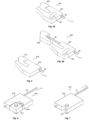
- the first, second and third actuators 321, 322, 323 are configured to move in relation to the frame 330 and configured to be operatively connected to the biopsy needle arrangement 20 in a similar manner as that described above in connection with figures 1, 2 and 3a-d .
- a triggering assembly 390 is connected at a proximal end of the body 31 of the actuator device 30.
- the triggering assembly 390 comprises trigger assembly parts, including a releaser 391 by which the proximal end of the first actuator 321 is held and whereby the sequence of the first, second and third actuators 321, 322, 323 being triggered to release their potential energy is initiated. Further details regarding a triggering assembly is outside the scope of the present disclosure.
- the needle 21 is connected to the first actuator 321 via the needle connector 370.
- a biassing spring 369 provides a biassing force between the needle sheath 22 and the tip portion 23 of the needle 21 in the initial loaded configuration where the first, second and third actuators 321, 322, 323 have been loaded with potential energy as discussed above.
- the biassing spring 369 provides the biassing force by means of a pin arrangement having a guider 361 and a bias pin 364, the bias pin 364 arranged in a guide groove 362 of the first actuator 321 and connected to the needle connector 370 via a connector hole 365.
- the biassing spring 369 When loading the first actuator 321 with potential energy via the spring 37, the biassing spring 369 will be compressed and provide a force that pulls the needle 21 in the proximal direction making the needle tip 23 abutting the distal end of the needle sheath 22, which is desirable as discussed above.
- Such an arrangement with a biassing spring 369 and bias pin 364 moving in the guide groove 362 also reduces the risk of damage to the needle tip 23 in case of "overloading" the spring 37 acting upon the first actuator 321 during the initial loading with potential energy as discussed above.
- the needle sheath 22 is connected to the second actuator 322 by means of the sheath connector 350, which is configured to interact with the third actuator 323 via the groove 36 as discussed above.
- the third actuator 321 with its pin 34, pin base 341 and third spring 39 is configured to interact with the second pin guider 345 as discussed above wherein the pin 34 cooperates with the groove 342 and the groove 36 in the sheath connector 350.
- the pin guider 345 is arranged with its guiding groove 346 facing upwards and below, in the z direction, the needle arrangement 20 and attached in a hollow 340 to the frame base 331.
- the second slider 33 is configured with a guide space 378 in which the pin guider 345 is accommodated.
- the pin guider 345 is provided with resilience by means of a pin guider spring 349, in contrast to the embodiments discussed above where the pin guider 345 is attached to a leaf spring 348 that is fixed to, or being a part of, the housing 31.
Landscapes
- Health & Medical Sciences (AREA)
- Life Sciences & Earth Sciences (AREA)
- Medical Informatics (AREA)
- Engineering & Computer Science (AREA)
- Biomedical Technology (AREA)
- Heart & Thoracic Surgery (AREA)
- Pathology (AREA)
- Molecular Biology (AREA)
- Surgery (AREA)
- Animal Behavior & Ethology (AREA)
- General Health & Medical Sciences (AREA)
- Public Health (AREA)
- Veterinary Medicine (AREA)
- Infusion, Injection, And Reservoir Apparatuses (AREA)
Claims (11)
- Biopsiesystem, umfassend eine Betätigungsvorrichtung (30) und eine Biopsienadelanordnung (20), wobei die Betätigungsvorrichtung (30) Folgendes umfasst: einen Rahmen (330), ein erstes Betätigungsgliedglied (321), ein zweites Betätigungsgliedglied (322) und ein drittes Betätigungsgliedglied (323), und die Biopsienadelanordnung (20) Folgendes umfasst: eine Nadelhülse (22) und eine Nadel (21),das erste, zweite und dritte Betätigungsglied (321, 322, 323) zum Bewegen im Verhältnis zu dem Rahmen (330) konfiguriert sind und mit der Biopsienadelanordnung (20) wirkverbunden ist,die Nadelhülse (22) ein proximales Ende (201) und ein distales Ende (202) aufweist, wobei die Nadelhülse (22) ein längliches Rohr darstellt, das eine Hülsenöffnung (203) an dem distalen Ende (202) der Nadelhülse (22) aufweist,die Nadel (21) ein proximales Ende (211) und ein distales Ende (212) und eine Länge aufweist, die größer ist als die Länge der Nadelhülse (22), wobei die Nadel (21) einen länglichen Schaftabschnitt (213), der zum Einpassen in ein Inneres der Nadelhülse (22) und zum Gleiten relativ zu dieser konfiguriert ist, und einen Spitzenabschnitt (23) umfasst, der mit dem Schaftabschnitt (213) verbunden ist und sich an dem distalen Ende (212) der Nadel (21) befindet, wobei der Spitzenabschnitt (23) eine Quererstreckung, oder Breite, aufweist, die größer ist als eine Quererstreckung, oder Breite, der Hülsenöffnung (203), die Biopsienadelanordnung (20) einen geschlossenen Zustand und einen offenen Zustand aufweist, wobei der Spitzenabschnitt (23) in dem geschlossenen Zustand an der Nadelhülse (22) anliegt und sich der Spitzenabschnitt (23) in dem offenen Zustand von dem distalen Ende (202) der Nadelhülse (22) erstreckt,das erste Betätigungsglied (321) zum Wirkverbinden mit der Nadel (21) konfiguriert ist und mit der Nadelanordnung (20) in ihrem geschlossenen Zustand zum Schieben der Nadel (21) distal in einer Gleitrichtung (x) relativ zu der Nadelhülse (22) um einen ersten Abstand, d1, konfiguriert ist, bei dem sich die Nadelanordnung (20) in ihrem offenen Zustand befindet,das zweite Betätigungsglied (322) zum Wirkverbinden mit der Nadelhülse (22) konfiguriert ist und mit der Nadelanordnung (20) in ihrem offenen Zustand zum Schieben der Nadelhülse (22) distal in der Gleitrichtung (x) relativ zu der Nadel (21) um einen zweiten Abstand, d2, konfiguriert ist,das dritte Betätigungsglied (323) zum Wirkverbinden mit der Nadelhülse (22) konfiguriert ist und mit der Nadelanordnung in ihrem offenen Zustand zum Schieben der Nadelhülse (22) distal in der Gleitrichtung (x) relativ zu der Nadel (21) um einen dritten Abstand, d3, konfiguriert ist, wobei d3 kleiner ist als d2, bei dem sich die Nadelanordnung (20) in ihrem geschlossenen Zustand befindet,das erste Betätigungsglied (321) zum Schieben der Nadel (21) mit einer Bewegung konfiguriert ist, die eine erste Höchstgeschwindigkeit, v1, aufweist, das zweite Betätigungsglied (322) zum Schieben der Nadelhülse (22) mit einer Bewegung konfiguriert ist, die eine zweite Höchstgeschwindigkeit, v2, aufweist, und das dritte Betätigungsglied (323) zum Schieben der Nadelhülse (22) mit einer Bewegung konfiguriert ist, die eine dritte Höchstgeschwindigkeit, v3, aufweist, wobei v3 kleiner ist als v2.
- Biopsiesystem nach Anspruch 1, wobei:das erste Betätigungsglied (321) ein erstes Gleitstück (32), das zum Gleiten relativ zu dem Rahmen (330) in der Gleitrichtung (x) konfiguriert ist, und eine erste Feder (37) umfasst, wobei die erste Feder (37) zum Vorspannen des ersten Gleitstücks (32) relativ zu dem Rahmen (330) konfiguriert ist,das zweite Betätigungsglied (322) ein zweites Gleitstück (33), das zum Gleiten relativ zu dem Rahmen (330) in der Gleitrichtung (x) konfiguriert ist, und eine zweite Feder (38) umfasst, wobei die zweite Feder (38) zum Vorspannen des zweiten Gleitstücks (33) relativ zu dem Rahmen (330) konfiguriert ist,das dritte Betätigungsglied (323) einen Stift (34) und eine dritte Feder (39) umfasst, wobei die dritte Feder (39) zum Vorspannen des Stiftes (34) relativ zu dem zweiten Gleitstück (33) konfiguriert ist.
- Biopsiesystem nach Anspruch 2, wobei:
die Betätigungsglieder (321, 322, 323) zum Vorspannen der Nadelhülse (22) in Bezug auf den Spitzenabschnitt (23) der Nadel (21) für alle relativen Positionen zwischen der Nadelhülse (22) und dem Spitzenabschnitt (23) konfiguriert sind. - Biopsiesystem nach Anspruch 2 oder 3, wobei:
der Stift (34) zum Zusammenwirken mit einer Nut (36) in einem an der Nadelhülse (22) angebrachten Hülsenverbinder (350) konfiguriert ist, wobei die Nut (36) entlang mindestens einer ersten Querrichtung (y1) relativ zu der Gleitrichtung (x) ausgerichtet ist und wobei der Stift (34) ferner zum Gleiten relativ zu dem zweiten Betätigungsglied (322) in einer zweiten Querrichtung (y2) relativ zu der Gleitrichtung (x) konfiguriert ist, wobei die zweite Querrichtung (y2) in einem Winkel (a) zu der ersten Querrichtung (y1) steht. - Biopsiesystem nach einem der Ansprüche 1 bis 4, wobei:
das erste Betätigungsglied (321) zum lösbaren Anbringen der Nadel (21) über einen Nadelverbinder (370) konfiguriert ist, wobei der Nadelverbinder (370) zum Lösen der Nadel (21) von dem ersten Betätigungsglied (321) konfiguriert ist, wenn die Nadel (21) einer Kraft in der Gleitrichtung (x) ausgesetzt ist, die eine Schwellenkraft überschreitet. - Biopsiesystem nach Anspruch 5, wobei:
das erste Betätigungsglied (321) zum Anbringen an einem ersten Nadelverbinderteil (371) des Nadelverbinders (370) konfiguriert ist und wobei:
sich das erste Nadelverbinderteil (371) von einem an der Nadel (21) angebrachten zweiten Nadelverbinderteil (372) löst und sich das zweite Nadelverbinderteil (372) distal in der Gleitrichtung (x) relativ zu dem ersten Nadelverbinderteil (371) bewegt, wenn sich die Nadel (21) von dem ersten Betätigungsglied (321) löst. - Biopsiesystem nach Anspruch 5, wobei:
der Nadelverbinder (370) ein an dem ersten Betätigungsglied (321) angebrachtes erstes Nadelverbinderteil (371) und ein zweites Nadelverbinderteil (372) umfasst, das zum Anbringen an der Nadel (21) konfiguriert ist, und wobei:
sich das erste Nadelverbinderteil (371) von dem zweiten Nadelverbinderteil (372) löst und sich das zweite Nadelverbinderteil (372) distal in der Gleitrichtung (x) relativ zu dem ersten Nadelverbinderteil (371) bewegt, wenn sich die Nadel (21) von dem ersten Betätigungsglied (321) löst. - Biopsiesystem nach einem der Ansprüche 1 bis 7, wobei:
das zweite Betätigungsglied (322) zum lösbaren Anbringen der Nadelhülse (22) über einen Hülsenverbinder (350) konfiguriert ist, wobei der Hülsenverbinder (350) zum Lösen der Nadelhülse (22) von dem zweiten Betätigungsglied (322) konfiguriert ist, wenn die Nadelhülse (22) einer Kraft in einer Richtung (-x) entgegengesetzt zu der Gleitrichtung (x) ausgesetzt ist, die eine Schwellenkraft überschreitet. - Biopsiesystem nach Anspruch 8, wobei:
das zweite Betätigungsglied (322) zum Anbringen an einem ersten Hülsenverbinderteil (351) des Hülsenverbinders (350) konfiguriert ist und wobei:
sich das erste Hülsenverbinderteil (351) von einem an der Nadelhülse (22) angebrachten zweiten Hülsenverbinderteil (352) löst und sich das erste Hülsenverbinderteil (351) distal in der Gleitrichtung (x) relativ zu dem zweiten Hülsenverbinderteil (352) bewegt, wenn sich die Nadelhülse (22) von dem zweiten Betätigungsglied (322) löst. - Biopsiesystem nach Anspruch 8, wobei:
der Hülsenverbinder (350) ein an dem zweiten Betätigungsglied (322) angebrachtes erstes Hülsenverbinderteil (351) und ein zweites Hülsenverbinderteil (352) umfasst, das zum Anbringen an der Nadelhülse (22) konfiguriert ist, und wobei:
sich das erste Hülsenverbinderteil (351) von dem zweiten Hülsenverbinderteil (352) löst und sich das erste Hülsenverbinderteil (351) distal in der Gleitrichtung (x) relativ zu dem zweiten Hülsenverbinderteil (352) bewegt, wenn sich die Nadelhülse (22) von dem zweiten Betätigungsglied (322) löst. - Biopsiesystem nach einem der Ansprüche 6, 7, 9 oder 10, wobei der Nadelverbinder (370) und/oder der Hülsenverbinder (350) eines der Folgenden ist:eine Einrastkonfiguration des jeweiligen ersten und zweiten Verbinderteils (371, 372, 351, 352),eine Abbrechkonfiguration des jeweiligen ersten und zweiten Verbinderteils (371, 372, 351, 352),eine Kraftschlusskonfiguration des jeweiligen ersten und zweiten Verbinderteils (371, 372, 351, 352).
Applications Claiming Priority (2)
| Application Number | Priority Date | Filing Date | Title |
|---|---|---|---|
| EP19201325.8A EP3799796A1 (de) | 2019-10-03 | 2019-10-03 | Biopsieanordnungen |
| PCT/EP2020/077367 WO2021064020A1 (en) | 2019-10-03 | 2020-09-30 | Biopsy arrangements |
Publications (3)
| Publication Number | Publication Date |
|---|---|
| EP4037571A1 EP4037571A1 (de) | 2022-08-10 |
| EP4037571B1 true EP4037571B1 (de) | 2025-05-07 |
| EP4037571C0 EP4037571C0 (de) | 2025-05-07 |
Family
ID=68137923
Family Applications (2)
| Application Number | Title | Priority Date | Filing Date |
|---|---|---|---|
| EP19201325.8A Withdrawn EP3799796A1 (de) | 2019-10-03 | 2019-10-03 | Biopsieanordnungen |
| EP20781369.2A Active EP4037571B1 (de) | 2019-10-03 | 2020-09-30 | Biopsieanordnungen |
Family Applications Before (1)
| Application Number | Title | Priority Date | Filing Date |
|---|---|---|---|
| EP19201325.8A Withdrawn EP3799796A1 (de) | 2019-10-03 | 2019-10-03 | Biopsieanordnungen |
Country Status (5)
| Country | Link |
|---|---|
| EP (2) | EP3799796A1 (de) |
| JP (1) | JP7599487B2 (de) |
| CN (1) | CN114599293A (de) |
| CA (1) | CA3152621A1 (de) |
| WO (1) | WO2021064020A1 (de) |
Family Cites Families (7)
| Publication number | Priority date | Publication date | Assignee | Title |
|---|---|---|---|---|
| US5779647A (en) * | 1995-06-07 | 1998-07-14 | Chau; Sonny | Automated biopsy instruments |
| WO2003026509A2 (en) * | 2001-09-20 | 2003-04-03 | The Government Of The United States Of America, Asrepresented By The Secretary Of The Department Of Health And Human Services | Tissue-sampling instrument and methods of use |
| DE102005062740B3 (de) * | 2005-12-22 | 2007-07-19 | INSTITUT FüR MIKROTECHNIK MAINZ GMBH | Biopsienadelset, Schussapparat und Biopsiegerät zur minimal-invasiven Entnahme von Gewebeproben |
| US20070208272A1 (en) * | 2006-03-03 | 2007-09-06 | Voegele James W | Biopsy device |
| US20110237976A1 (en) * | 2008-12-03 | 2011-09-29 | The Regents Of The University Of Michigan | Biopsy device having hemostatic control |
| ES2875575T3 (es) * | 2013-03-20 | 2021-11-10 | Bard Peripheral Vascular Inc | Dispositivo de biopsia |
| WO2018028780A1 (en) * | 2016-08-10 | 2018-02-15 | Saga Surgical Ab | A biopsy needle arrangement |
-
2019
- 2019-10-03 EP EP19201325.8A patent/EP3799796A1/de not_active Withdrawn
-
2020
- 2020-09-30 EP EP20781369.2A patent/EP4037571B1/de active Active
- 2020-09-30 CA CA3152621A patent/CA3152621A1/en active Pending
- 2020-09-30 WO PCT/EP2020/077367 patent/WO2021064020A1/en not_active Ceased
- 2020-09-30 CN CN202080069842.6A patent/CN114599293A/zh active Pending
- 2020-09-30 JP JP2022520397A patent/JP7599487B2/ja active Active
Also Published As
| Publication number | Publication date |
|---|---|
| EP3799796A1 (de) | 2021-04-07 |
| EP4037571A1 (de) | 2022-08-10 |
| JP7599487B2 (ja) | 2024-12-13 |
| US20220346762A1 (en) | 2022-11-03 |
| CA3152621A1 (en) | 2021-04-08 |
| WO2021064020A1 (en) | 2021-04-08 |
| CN114599293A (zh) | 2022-06-07 |
| EP4037571C0 (de) | 2025-05-07 |
| JP2022550845A (ja) | 2022-12-05 |
Similar Documents
| Publication | Publication Date | Title |
|---|---|---|
| US5527334A (en) | Disposable, retractable lancet | |
| US5476099A (en) | High velocity tissue sample cutter | |
| US7775989B2 (en) | Needle biopsy forceps with integral sample ejector | |
| CA2331444C (en) | Reusable automated biopsy needle handle | |
| US7837631B2 (en) | Biopsy forceps with removable jaw segments | |
| EP2213246B1 (de) | Expandierbares Nadel-Nähgerät und relevante Handgriffanordnung | |
| EP1348378A1 (de) | Mehrfach bewegliche Biopsievorrichtung zur wiederholten Probenentnahme | |
| US20120209140A1 (en) | Tissue Sampling Device | |
| DE19906592A1 (de) | Medizinisches Instrument für die kombinierte Verwendung mit einem Endoskop | |
| TWI739955B (zh) | 生檢裝置之手柄 | |
| AU2020360621B2 (en) | Biopsy arrangements | |
| US9974526B2 (en) | Ultrasonic endoscope biopsy system with treatment tool having various rigidity sections | |
| EP2407113B1 (de) | Gerät zur Entnahme von mindestens einer Probe Gewebe | |
| US10973501B2 (en) | Endoscopic treatment tool and handle | |
| US10285672B2 (en) | Adjustable throw percutaneous needle | |
| US12629139B2 (en) | Biopsy arrangements | |
| US11464501B2 (en) | Biopsy device | |
| EP3799796A1 (de) | Biopsieanordnungen | |
| US20240180532A1 (en) | Needle arrangement for biopsy | |
| US20140358030A1 (en) | Device for Taking at Least One Sample of Tissue |
Legal Events
| Date | Code | Title | Description |
|---|---|---|---|
| STAA | Information on the status of an ep patent application or granted ep patent |
Free format text: STATUS: UNKNOWN |
|
| STAA | Information on the status of an ep patent application or granted ep patent |
Free format text: STATUS: THE INTERNATIONAL PUBLICATION HAS BEEN MADE |
|
| PUAI | Public reference made under article 153(3) epc to a published international application that has entered the european phase |
Free format text: ORIGINAL CODE: 0009012 |
|
| STAA | Information on the status of an ep patent application or granted ep patent |
Free format text: STATUS: REQUEST FOR EXAMINATION WAS MADE |
|
| 17P | Request for examination filed |
Effective date: 20220325 |
|
| AK | Designated contracting states |
Kind code of ref document: A1 Designated state(s): AL AT BE BG CH CY CZ DE DK EE ES FI FR GB GR HR HU IE IS IT LI LT LU LV MC MK MT NL NO PL PT RO RS SE SI SK SM TR |
|
| DAV | Request for validation of the european patent (deleted) | ||
| DAX | Request for extension of the european patent (deleted) | ||
| STAA | Information on the status of an ep patent application or granted ep patent |
Free format text: STATUS: EXAMINATION IS IN PROGRESS |
|
| 17Q | First examination report despatched |
Effective date: 20231215 |
|
| GRAP | Despatch of communication of intention to grant a patent |
Free format text: ORIGINAL CODE: EPIDOSNIGR1 |
|
| STAA | Information on the status of an ep patent application or granted ep patent |
Free format text: STATUS: GRANT OF PATENT IS INTENDED |
|
| INTG | Intention to grant announced |
Effective date: 20250210 |
|
| GRAS | Grant fee paid |
Free format text: ORIGINAL CODE: EPIDOSNIGR3 |
|
| GRAA | (expected) grant |
Free format text: ORIGINAL CODE: 0009210 |
|
| STAA | Information on the status of an ep patent application or granted ep patent |
Free format text: STATUS: THE PATENT HAS BEEN GRANTED |
|
| AK | Designated contracting states |
Kind code of ref document: B1 Designated state(s): AL AT BE BG CH CY CZ DE DK EE ES FI FR GB GR HR HU IE IS IT LI LT LU LV MC MK MT NL NO PL PT RO RS SE SI SK SM TR |
|
| REG | Reference to a national code |
Ref country code: GB Ref legal event code: FG4D |
|
| REG | Reference to a national code |
Ref country code: CH Ref legal event code: EP |
|
| REG | Reference to a national code |
Ref country code: DE Ref legal event code: R096 Ref document number: 602020050920 Country of ref document: DE |
|
| REG | Reference to a national code |
Ref country code: IE Ref legal event code: FG4D |
|
| U01 | Request for unitary effect filed |
Effective date: 20250604 |
|
| U07 | Unitary effect registered |
Designated state(s): AT BE BG DE DK EE FI FR IT LT LU LV MT NL PT RO SE SI Effective date: 20250616 |
|
| PG25 | Lapsed in a contracting state [announced via postgrant information from national office to epo] |
Ref country code: ES Free format text: LAPSE BECAUSE OF FAILURE TO SUBMIT A TRANSLATION OF THE DESCRIPTION OR TO PAY THE FEE WITHIN THE PRESCRIBED TIME-LIMIT Effective date: 20250507 |
|
| PG25 | Lapsed in a contracting state [announced via postgrant information from national office to epo] |
Ref country code: GR Free format text: LAPSE BECAUSE OF FAILURE TO SUBMIT A TRANSLATION OF THE DESCRIPTION OR TO PAY THE FEE WITHIN THE PRESCRIBED TIME-LIMIT Effective date: 20250808 Ref country code: NO Free format text: LAPSE BECAUSE OF FAILURE TO SUBMIT A TRANSLATION OF THE DESCRIPTION OR TO PAY THE FEE WITHIN THE PRESCRIBED TIME-LIMIT Effective date: 20250807 |
|
| PG25 | Lapsed in a contracting state [announced via postgrant information from national office to epo] |
Ref country code: PL Free format text: LAPSE BECAUSE OF FAILURE TO SUBMIT A TRANSLATION OF THE DESCRIPTION OR TO PAY THE FEE WITHIN THE PRESCRIBED TIME-LIMIT Effective date: 20250507 |
|
| PG25 | Lapsed in a contracting state [announced via postgrant information from national office to epo] |
Ref country code: HR Free format text: LAPSE BECAUSE OF FAILURE TO SUBMIT A TRANSLATION OF THE DESCRIPTION OR TO PAY THE FEE WITHIN THE PRESCRIBED TIME-LIMIT Effective date: 20250507 |
|
| PG25 | Lapsed in a contracting state [announced via postgrant information from national office to epo] |
Ref country code: RS Free format text: LAPSE BECAUSE OF FAILURE TO SUBMIT A TRANSLATION OF THE DESCRIPTION OR TO PAY THE FEE WITHIN THE PRESCRIBED TIME-LIMIT Effective date: 20250807 |
|
| U20 | Renewal fee for the european patent with unitary effect paid |
Year of fee payment: 6 Effective date: 20250916 |
|
| PG25 | Lapsed in a contracting state [announced via postgrant information from national office to epo] |
Ref country code: IS Free format text: LAPSE BECAUSE OF FAILURE TO SUBMIT A TRANSLATION OF THE DESCRIPTION OR TO PAY THE FEE WITHIN THE PRESCRIBED TIME-LIMIT Effective date: 20250907 |
|
| U1N | Appointed representative for the unitary patent procedure changed after the registration of the unitary effect |
Representative=s name: OEBERG & SJOEBERG AB; SE |
|
| PG25 | Lapsed in a contracting state [announced via postgrant information from national office to epo] |
Ref country code: SM Free format text: LAPSE BECAUSE OF FAILURE TO SUBMIT A TRANSLATION OF THE DESCRIPTION OR TO PAY THE FEE WITHIN THE PRESCRIBED TIME-LIMIT Effective date: 20250507 |
|
| PG25 | Lapsed in a contracting state [announced via postgrant information from national office to epo] |
Ref country code: CZ Free format text: LAPSE BECAUSE OF FAILURE TO SUBMIT A TRANSLATION OF THE DESCRIPTION OR TO PAY THE FEE WITHIN THE PRESCRIBED TIME-LIMIT Effective date: 20250507 |
|
| PG25 | Lapsed in a contracting state [announced via postgrant information from national office to epo] |
Ref country code: SK Free format text: LAPSE BECAUSE OF FAILURE TO SUBMIT A TRANSLATION OF THE DESCRIPTION OR TO PAY THE FEE WITHIN THE PRESCRIBED TIME-LIMIT Effective date: 20250507 |
|
| PLBE | No opposition filed within time limit |
Free format text: ORIGINAL CODE: 0009261 |
|
| STAA | Information on the status of an ep patent application or granted ep patent |
Free format text: STATUS: NO OPPOSITION FILED WITHIN TIME LIMIT |
|
| REG | Reference to a national code |
Ref country code: CH Ref legal event code: L10 Free format text: ST27 STATUS EVENT CODE: U-0-0-L10-L00 (AS PROVIDED BY THE NATIONAL OFFICE) Effective date: 20260318 |
|
| 26N | No opposition filed |
Effective date: 20260210 |
|
| REG | Reference to a national code |
Ref country code: CH Ref legal event code: H13 Free format text: ST27 STATUS EVENT CODE: U-0-0-H10-H13 (AS PROVIDED BY THE NATIONAL OFFICE) Effective date: 20260425 |