EP4037437A1 - Lighting system and method for providing light to an area - Google Patents
Lighting system and method for providing light to an area Download PDFInfo
- Publication number
- EP4037437A1 EP4037437A1 EP21154240.2A EP21154240A EP4037437A1 EP 4037437 A1 EP4037437 A1 EP 4037437A1 EP 21154240 A EP21154240 A EP 21154240A EP 4037437 A1 EP4037437 A1 EP 4037437A1
- Authority
- EP
- European Patent Office
- Prior art keywords
- led
- light
- unit
- lighting system
- moisture
- Prior art date
- Legal status (The legal status is an assumption and is not a legal conclusion. Google has not performed a legal analysis and makes no representation as to the accuracy of the status listed.)
- Granted
Links
Images



Classifications
-
- H—ELECTRICITY
- H05—ELECTRIC TECHNIQUES NOT OTHERWISE PROVIDED FOR
- H05B—ELECTRIC HEATING; ELECTRIC LIGHT SOURCES NOT OTHERWISE PROVIDED FOR; CIRCUIT ARRANGEMENTS FOR ELECTRIC LIGHT SOURCES, IN GENERAL
- H05B45/00—Circuit arrangements for operating light-emitting diodes [LED]
- H05B45/20—Controlling the colour of the light
-
- H—ELECTRICITY
- H05—ELECTRIC TECHNIQUES NOT OTHERWISE PROVIDED FOR
- H05B—ELECTRIC HEATING; ELECTRIC LIGHT SOURCES NOT OTHERWISE PROVIDED FOR; CIRCUIT ARRANGEMENTS FOR ELECTRIC LIGHT SOURCES, IN GENERAL
- H05B47/00—Circuit arrangements for operating light sources in general, i.e. where the type of light source is not relevant
- H05B47/10—Controlling the light source
- H05B47/105—Controlling the light source in response to determined parameters
Definitions
- the present invention relates to a lighting system and a method for providing light to an area.
- the lighting system corresponds to a luminaire.
- the lighting system comprises two or more luminaires.
- LED light sources comprising one or more LEDs (light emitting diodes), such as one or more of organic LEDs, inorganic LEDs, LEDs with secondary emission etc.
- LED light sources are more and more used instead of more traditional light sources comprising or corresponding to filament lamps and/or gas-discharge lamps.
- the use of LEDs for providing light has many advantages such as reduced energy consumption, longer lifetime, lighting of variable color etc.
- LED light sources configured to emit white light are used for lighting purposes.
- Such LED light sources may emit light of a spectrum that causes more blinding (of persons) compared to more traditional light sources in case of humid air, because the white light emitted by the LED light sources is more reflected by the humid air compared to the light emitted by a traditional light source, such as a gas discharge lamp.
- a traditional light source such as a gas discharge lamp.
- a traditional light source such as a gas discharge lamp.
- a traditional light source such as a gas discharge lamp.
- a traditional light source such as a gas discharge lamp.
- a traditional light source such as a gas discharge lamp.
- a light source emitting white light e.g. of correlated color temperature (CCT) of 6500 K
- CCT correlated color temperature
- an object of the present invention to provide an improved lighting system using an LED light source for providing light to an area, e.g. a street area, both in dry and wet conditions.
- an LED light source for providing light to an area, for which the above described drawbacks in case of moisture (e.g. humid air and/or wet ground) are reduced, in particular overcome.
- a lighting system for providing light to an area.
- the system comprises at least one LED light source (LED-LS) configured to emit white light, and a control unit configured to control a light emission of the at least one LED-LS.
- the control unit is configured to control the light emission of the at least one LED-LS based on moisture information on a moisture in the area such that, in case the moisture information fulfills a condition regarding the moisture in the area, the control unit controls the at least one LED-LS to emit only light of a spectrum comprising a reflection probability of light-reflection on water drops smaller than a probability threshold.
- the control unit is configured to control the light emission of white light of the at least one LED-LS such that, when the at least one LED-LS emits light (light emitting state of the at least one LED-LS), the at least one LED-LS stops emitting light of a spectrum comprising a reflection probability of light-reflection on water drops greater than or equal to the probability threshold. That is, in case the moisture information fulfills the condition, the control unit is configured to control the light emission of the at least one LED-LS such that the control unit controls the at least one LED-LS to emit light of one or more wavelengths for which the reflection probability of light-reflection on water drops is smaller than the probability threshold.
- the lighting system may provide white light to the area in case the moisture information does not fulfill the condition.
- an LED-LS providing white light for illumination has a good efficiency factor with regard to the electrical energy needed for providing the lighting in the area.
- the lighting system may switch from providing white light to only providing light of the spectrum comprising a reflection probability of light-reflection on water drops smaller than the probability threshold, for providing the lighting in the area. This is advantageous, because this reduces the blinding (of a person in the area) caused by the light emission compared to a case, in which the light emission is not changed and, thus, emission of white light is continued. Reducing the blinding increases the visibility for a person present in the area.
- Emitting only light of the spectrum comprising a reflection probability of light-reflection on water drops smaller than the probability threshold may decrease the efficiency factor of the light emission by the lighting system. Therefore, the control unit is configured to change the light emission of white light to light of the spectrum comprising a reflection probability of light-reflection on water drops smaller than the probability threshold only in case the condition is fulfilled. Thus, in case the condition is not fulfilled, the white light with the good efficiency factor is emitted.
- the lighting system according to the first aspect is advantageous, because it allows reducing blinding caused by light emission of the LED-LS of the system in case the condition regarding the moisture in the area, e.g. a certain moisture level or presence of rain or fog, is fulfilled.
- the lighting system allows to improve the efficiency of the light emission by allowing white light emission, in case the condition is not fulfilled (e.g. good weather, no rain, no fog).
- the moisture in the area comprises the moisture of the ground in the area and the moisture of the air in the area.
- the term humidity is used for referring to the moisture in the air of the area.
- moisture is to be understood as referring to water in the form of drops (i.e. water drops) either in the air, in a substance or on a surface (e.g. the ground in the area).
- the area maybe an outdoor area, e.g. a street area, a harbor/port area, airport area, forest area etc.
- the area maybe an indoor area, e.g. indoor skiing hall, indoor pool, thermal bath etc.
- the area may be a combination of an outdoor and indoor area, such as a sports stadium or swimming hall, optionally with a movable roof.
- the LED-LS may comprise a plurality of LEDs (light emitting diodes), such as at least one of organic LEDs, inorganic LEDs, LEDs with secondary emission etc.
- LEDs light emitting diodes
- the control unit may comprise or correspond to a processor, a microprocessor, a controller, a microcontroller, a field programmable gate array (FPGA), an application specific integrated circuit (ASIC) or any combination of them.
- a processor a microprocessor, a controller, a microcontroller, a field programmable gate array (FPGA), an application specific integrated circuit (ASIC) or any combination of them.
- FPGA field programmable gate array
- ASIC application specific integrated circuit
- the moisture information fulfills the condition in case the moisture information informs on a humidity level greater than a humidity threshold.
- the moisture information may fulfill the condition in case the moisture information informs on precipitation and/or fog.
- the moisture information may fulfill the condition in case the moisture information informs on a precipitation intensity greater than an intensity threshold, i.e. on an amount of precipitation greater than a threshold amount.
- the moisture information may fulfill the condition in case the moisture information informs on a moisture level of the ground in the area greater than a moisture threshold.
- the moisture information may inform on at least one of a presence of a weather condition comprising or corresponding to precipitation and/or fog; a degree of a weather condition comprising or corresponding to precipitation and/or fog; a humidity level; and a moisture level of the ground.
- the humidity level may correspond to the absolute humidity in the area, i.e. the total mass of water vapor present in a given volume or mass of air.
- the humidity level may correspond to a relative humidity. Precipitation may comprise or correspond to rain, snow, sleet, hail etc.
- the moisture level may correspond to an absolute moisture level or a relative moisture level.
- the lighting system comprises a weather condition sensor unit configured to detect precipitation and/or fog in the area and provide the detection result as the moisture information to the control unit.
- the weather condition sensor unit may comprise or correspond to a precipitation and/or fog sensor unit.
- the lighting system may comprise a humidity sensor unit configured to detect a humidity level of the humidity in the area and provide the detection result as the moisture information to the control unit.
- the lighting system may comprise a moisture sensor unit configured to detect a moisture level of the ground in the area and provide the detection result as the moisture information to the control unit.
- the lighting system may comprise a communication unit configured to receive the moisture information, e.g. from a weather forecast station, and provide the moisture information to the control unit.
- the weather condition unit may be configured to detect the presence of precipitation and/or fog in the area and optionally the degree of precipitation (i.e. amount/intensity of precipitation) and/or fog (density of fog).
- degree of precipitation i.e. amount/intensity of precipitation
- fog density of fog
- the communication unit may be configured to communicate wirelessly and/or wire-bound for receiving the moisture information.
- the communication unit may be configured to communicate with a weather forecast station for receiving information on the weather condition in the area as the moisture information.
- the communication unit may be a part of the control unit.
- the wireless communication unit maybe configured to communicate wirelessly using radio waves.
- the communication unit may be implemented by any means known in the art.
- the lighting system may generate the moisture information regarding the moisture in the area by itself using at least one of a weather condition unit, precipitation and/or fog sensor unit, a humidity sensor unit and a moisture sensor unit.
- the control unit may be configured to determine based on the generated moisture information that the condition regarding the moisture in the area is fulfilled, e.g. presence of precipitation, the humidity level in the area is greater than a humidity threshold and/or the moisture level of the ground is greater than a moisture threshold.
- the control unit may react thereto, by controlling the light emission of the at least one LED light source such that the light emission is changed from a first emission state to a second emission state.
- the at least one LED-LS In the first emission state, the at least one LED-LS emits white light, when the control unit controls the at least one LED-LS to emit light. In the second emission state, the at least one LED-LS emits only light of the spectrum comprising a reflection probability of light-reflection on water drops smaller than the probability threshold.
- the control unit may determine that that the condition is fulfilled.
- a moisture threshold e.g. wet street due to rainfall
- the system may receive the moisture information regarding the moisture in the area from a weather forecast station.
- the control unit may already react to a received moisture information fulfilling the condition before the condition is actually fulfilled in the area.
- the communication unit receives from the weather forecast station information informing on heavy rain fall for a certain time and optionally date, e.g. on 12.05.2020 at 12.00 o'clock, and the condition corresponds to such heavy rain fall, then the control unit may determine based on the received information from the weather forecast station that at that time and optionally date (e.g. 12.05.2020 at 12.00 o'clock), the condition regarding the moisture in the area will be fulfilled.
- the control unit may be configured to control the at least one LED-LS such that at that time and optionally date (12.05.2020 at 12.00 o'clock) the at least one LED-LS emits only light of the spectrum comprising a reflection probability of light-reflection on water drops smaller than the probability threshold.
- control unit may be configured to control the at least one LED-LS such that already a time period (e.g. 30 minutes) before that time and optionally date (12.05.2020 at 12.00 o'clock) the at least one LED-LS emits only light of the spectrum comprising a reflection probability of light-reflection on water drops smaller than the probability threshold.
- the communication unit allows the control unit to react to the condition already before the condition is fulfilled.
- control unit For evaluating the moisture information received from one or more sensors of the lighting system, such as the aforementioned sensors, and/or the information received from a weather forecast station, the control unit may use one or more look-up tables and/or one or more algorithms.
- the reflection probability of light-reflection on water drops may correspond to a relative scattering coefficient and the probability threshold may correspond to a threshold for the relative scattering coefficient.
- the reflection probability of light-reflection on water drops may correspond to a relative Rayleigh scattering coefficient and the probability threshold may correspond to a threshold for the relative Rayleigh scattering coefficient.
- the relative scattering coefficient may be a relative Rayleigh scattering coefficient.
- the at least one LED-LS comprises a first LED unit configured to emit the white light, and a second LED unit configured to emit light of a spectrum comprising a reflection probability of light-reflection on water drops smaller than the probability threshold.
- the control unit may be configured to control the light emission of the at least one LED-LS such that the first LED unit emits light, in case the moisture information does not fulfill the condition, and only the second LED unit emits light, in case the moisture information fulfills the condition.
- control unit may be configured to control the light emission of the at least one LED-LS such that only the first LED unit emits light, in case the moisture information does not fulfill the condition.
- the first LED unit and the second LED unit each may correspond to an LED chip.
- the second LED unit is configured to emit light of a spectrum comprising a relative emission intensity greater than 20% between a wavelength of 580 nm and a wavelength of 605 nm.
- the second LED unit may be configured to emit light of a spectrum comprising, between the wavelength of 580 nm and the wavelength of 605 nm, a relative emission intensity between 20% and 100%. That is, the relative emission intensity of the spectrum may be equal to 100% at a wavelength between the wavelength of 580 nm and the wavelength of 605 nm.
- the second LED unit may be configured to emit light of a spectrum comprising its main part (i.e. the main part of the spectrum) between the wavelength of 580 nm and the wavelength of 605 nm.
- the second LED unit may be configured to emit light of a spectrum comprising 20% relative emission intensity at the wavelength of 580 nm and the wavelength of 605 nm.
- the second LED unit may be configured to emit light of a spectrum comprising a relative emission intensity greater than 20% between a wavelength of 542 nm and a wavelength of 670 nm.
- the second LED unit may be configured to emit light of a spectrum comprising, between the wavelength of 542 nm and the wavelength of 670 nm, a relative emission intensity between 20% and 100%. That is, the relative emission intensity of the spectrum may be equal to 100% at a wavelength between the wavelength of 542 nm and the wavelength of 670 nm.
- the second LED unit may be configured to emit light of a spectrum comprising its main part (i.e. the main part of the spectrum) between the wavelength of 542 nm and the wavelength of 670 nm.
- the second LED unit may be configured to emit light of a spectrum comprising 20% relative emission intensity at the wavelength of 542 nm and the wavelength of 670 nm.
- the second LED unit may be configured to emit light of a spectrum between a wavelength of 565 nm and a wavelength of 620 nm or a wavelength of 527 nm and a wavelength of 685 nm.
- the spectrum comprises a Gaussian spectral shape.
- the spectrum may be a symmetrical spectrum.
- the second LED unit may be a monochromatic amber LED unit configured to emit amber light.
- the second LED unit may be a phosphor converted LED unit configured to emit amber light.
- the first LED unit is configured to emit white light with a variable correlated color temperature (CCT) and the control unit is configured to vary the CCT of the white light.
- CCT variable correlated color temperature
- the first LED unit may be configured to emit white light with a variable CCT between 2700 and 4000 K.
- the first LED unit may be configured to emit white light with a CCT of 6500 K.
- the lighting system comprises a lens unit arranged to modulate the light emitted by the second LED unit.
- the lens unit comprises an improved beam geometry reducing the reflection probability of light-reflection on water drops of the light emitted by the second LED unit.
- the lens unit may correspond to a lens arrangement comprising a plurality of lenses.
- the lens unit is arranged to reduce reflectivity of light, emitted by the second LED unit, on a wet ground in the area. That is, the lens unit may be arranged to reduce reflectivity of light, emitted by the second LED unit, on a ground in the area, wherein the moisture level of the ground is above a moisture threshold (e.g. a water level or water amount above a threshold value is present on the ground).
- a moisture threshold e.g. a water level or water amount above a threshold value is present on the ground.
- the lighting system is a luminaire.
- the lighting system may be an outdoor luminaire, such as a street lighting luminaire, a harbor lighting luminaire, a floodlight luminaire (e.g. for a sports stadium), a spotlight luminaire (e.g. for a sports stadium), a car headlights luminaire etc.
- a street lighting luminaire such as a street lighting luminaire, a harbor lighting luminaire, a floodlight luminaire (e.g. for a sports stadium), a spotlight luminaire (e.g. for a sports stadium), a car headlights luminaire etc.
- the at least one LED-LS may correspond to at least one LED module
- the luminaire may comprise a driver module for driving the at least one LED module
- the driver module may comprise the control unit.
- the control unit may be extern to the driver module (i.e. not a part of the driver module).
- the luminaire may comprise a housing and the at least one LED-LS (LED module), the driver module and the control unit may be arranged inside the housing.
- the at least one LED-LS (LED module ) is arranged in the housing such that the at least one LED-LS (LED module) is configured to emit light from inside the housing via an opening and/or a transparent section of the housing to the outside of the housing.
- the driver module is configured to provide the at least one LED-LS (LED module) with electrical energy.
- the driver module may comprise an optional power factor correction (PFC) circuit, a power conversion circuit (AC/DC and/or DC/DC power conversions circuit) and/or an optional filter circuit.
- the power conversion circuit may comprise one or more actively switched power converters (in particular at least one actively switched DC/DC power converter and/or at least one actively switched AC/DC power converter).
- the control unit is configured to control the light emission of the at least one LED-LS (LED module) by controlling the electrically energy supplied by the driver module to the at least one LED-LS (LED module).
- the control unit may be configured to control switching of the actively switched power converter for controlling the electrical energy supplied to the at least one LED-LS (LED module) and, thus, the light emission by the at least one LED-LS (LED module).
- active power converter such as at least one boost converter, buck converter, flyback converter and/or resonant converter
- the control unit may be configured to control switching of the actively switched power converter for controlling the electrical energy supplied to the at least one LED-LS (LED module) and, thus, the light emission by the at least one LED-LS (LED module).
- the higher the electrical energy e.g. time-averaged electrical energy over a time period
- current e.g. time-averaged current over a time period
- the lighting system comprises two or more LED-LS and each LED-LS is a luminaire.
- Each LED-LS may be an outdoor luminaire, such as a street lighting luminaire, a harbor lighting luminaire, a floodlight luminaire, a spotlight luminaire, e.g. for a sports stadium, car headlights luminaire etc.
- a street lighting luminaire such as a street lighting luminaire, a harbor lighting luminaire, a floodlight luminaire, a spotlight luminaire, e.g. for a sports stadium, car headlights luminaire etc.
- the above description of the lighting system maybe valid for each luminaire of the lighting system, in case the lighting system comprises two or more LED-LS and each LED-LS is a luminaire.
- At least one of the two or more LED-LS comprises a local control unit configured to control the light emission of the respective LED-LS based on moisture information on the moisture in the area such that in case the moisture information fulfills the condition regarding the moisture in the area, the local control unit controls the respective LED-LS to emit only light of a spectrum comprising a reflection probability of light-reflection on water drops smaller than the probability threshold.
- each of the two or more LED-LS comprises a local control unit configured to control the light emission of the respective LED-LS based on moisture information on the moisture in the area such that in case the moisture information fulfills the condition regarding the moisture in the area, the local control unit controls the respective LED-LS to emit only light of a spectrum comprising a reflection probability of light-reflection on water drops smaller than the probability threshold.
- the control unit may be part of one of the two or more LED-LS and may be configured to control the light emission of the two or more LED-LS.
- the two or more LED-LS of the lighting system according to the further embodiment maybe referred to two or more luminaires, because each LED-LS of the lighting system according to the further embodiment is a luminaire.
- the light emission by each of the two or more luminaires of the lighting system of the further embodiment may be controlled according to different alternatives in dependence of the moisture in the area.
- the control unit of the system may be a single central control unit that is configured to control the light emission of the two or more luminaires based on moisture information on the moisture in the area such that, in case the moisture information fulfills the condition regarding the moisture in the area, the control unit controls the two or more luminaires to emit only light of a spectrum comprising a reflection probability of light-reflection on water drops smaller than a probability threshold.
- control unit of the system may be part of one of the two or more luminaires and may be configured to control the light emission of the two or more luminaires based on moisture information on the moisture in the area such that, in case the moisture information fulfills the condition regarding the moisture in the area, the control unit controls the two or more luminaires to emit only light of a spectrum comprising a reflection probability of light-reflection on water drops smaller than a probability threshold.
- At least one of the two or more luminaires may comprise a local control unit configured to control the light emission of the respective luminaires based on moisture information on the moisture in the area such that in case the moisture information fulfills the condition regarding the moisture in the area, the local control unit controls the respective luminaire to emit only light of a spectrum comprising a reflection probability of light-reflection on water drops smaller than the probability threshold.
- each of the two or more luminaires may comprise a local control unit configured to control the light emission of the respective luminaire based on moisture information on the moisture in the area such that in case the moisture information fulfills the condition regarding the moisture in the area, the local control unit controls the respective luminaire to emit only light of a spectrum comprising a reflection probability of light-reflection on water drops smaller than the probability threshold.
- a fifth alternative corresponds to the third alternative, wherein the control unit of the system corresponds to the local control unit of the at least one luminaire of the two or more luminaires.
- a sixth alternative corresponds to the fourth alternative, wherein the control unit of the system corresponds to a local control unit of one of the two or more luminaires.
- control unit of the lighting system may be valid for the local control unit of a respective luminaire.
- Each LED-LS may comprise a communication unit for communicating, in particular wirelessly, with other devices.
- the other devices may comprise or correspond to the other LED-LS of the lighting system.
- other devices may correspond to mobile end devices, such as mobile phones, vehicles, local weather stations, weather forecast stations etc.
- the communication unit of each LED-LS (luminaire) may be configured to communicate with vehicles driving on a street at the street area, mobile end devices carried by persons walking on a pedestrian at the street area and a local weather station that may be present at the street area for monitoring the weather condition at the street area.
- the local weather station may be configured to detect the humidity level in the street area, the moisture level of the ground in the street area (e.g. moisture level of the street) and/or the presence and optionally amount of precipitation and/or fog in the street area.
- the communication unit of each LED-LS (luminaire) may be configured to receive moisture information regarding the moisture at the street area from the vehicles, mobile end devices and the local weather station.
- the communication between each of the LED-LS (luminaires) and other devices maybe wireless.
- the wireless communication may be based on radio waves.
- the communication unit may be configured to communicate with ships and, thus, the communication unit of each LED-LS (luminaire) may be configured to receive moisture information regarding the moisture at the harbor area from the ships.
- the first LED unit and the second LED unit form an LED module.
- the lighting system may be a luminaire.
- the at least one LED-LS corresponds to the lighting means of that luminaire.
- the lighting system may comprise at least two LED-LS, wherein each LED-LS corresponds to a luminaire.
- each luminaire comprises lighting means.
- the description of the lighting system being a luminaire according to the above-mentioned embodiment is correspondingly valid for describing each luminaire of the system according to the further embodiment.
- a method for providing light to an area comprising the step of emitting, by at least one LED light source, LED-LS, white light.
- the method further comprises the step of controlling, by a control unit, a light emission of the at least one LED-LS based on moisture information on a moisture in the area such that in case the moisture information fulfills a condition regarding the moisture in the area, the control unit controls the at least one LED-LS to emit only light of a spectrum comprising a reflection probability of light-reflection on water drops smaller than a probability threshold.
- the method according to the second aspect of the present invention achieves the same advantages as the lighting system according to the first aspect of the invention.
- the above description of the LED-LS and control unit of the lighting system according to the first aspect of the present invention is correspondingly valid for the LED-LS and control unit used for performing the method according to the second aspect of the present invention.
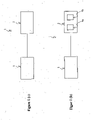
- Figure 1 (a) schematically shows a lighting system according to the first aspect of the present invention.
- the lighting system 1 for providing light to an area comprises an LED light source (LED-LS) 2 and a control unit 3.
- the lighting system 1 may comprise more than one LED-LS 2.
- the at least one LED-LS 2 is configured to emit white light and the control unit 3 is configured to control a light emission of the at least one LED-LS 2.
- the control unit 3 is configured to control the light emission of the at least one LED-LS 2 based on moisture information on a moisture in the area such that, in case the moisture information fulfills a condition regarding the moisture in the area (e.g. rain present in the area), the control unit 3 controls the at least one LED-LS 2 to emit only light of a spectrum comprising a reflection probability of light-reflection on water drops smaller than a probability threshold.
- the lighting system 1 of Figure 1 (a) may reduce blinding of persons present in the area that is caused by the light emission of the at least one LED-LS 2, in case the condition regarding the moisture in the area is fulfilled (e.g. rain present in the area). Namely, the light of the spectrum comprising a reflection probability of light-reflection on water drops smaller than a probability threshold is less reflected on water drops, such as rain drops, compared to light of wavelengths respectively a spectrum comprising a reflection probability of light-reflection on water drops greater than or equal to the probability threshold.
- Figure 1 (b) schematically shows a lighting system according to an embodiment of the present invention.
- the lighting system of Figure 1 (b) corresponds to the lighting system of Figure 1 (a) . Therefore, the above description of the system of Figure 1 (a) is also valid for the lighting system of Figure 1 (b) and in the following mainly additional features shown in Figure 1 (b) are described.
- the at least one LED-LS 2 may optionally comprise a first LED unit 4a configured to emit white light, and a second LED unit 4b configured to emit light of the spectrum comprising a reflection probability of light-reflection on water drops smaller than the probability threshold.
- the control unit 3 may be configured to control the light emission of the at least one LED-LS 2 such that the first LED unit 4a emits light, in case the moisture information does not fulfill the condition, and only the second LED unit 4b emits light, in case the moisture information fulfills the condition.
- first LED unit 4a and the second LED unit 4b For a more detailed description of the first LED unit 4a and the second LED unit 4b reference is made to the above description of the first LED unit and second LED unit of the lighting system according to the first aspect of the present invention.
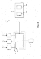
- FIG. 2 schematically shows a lighting system according to an embodiment of the present invention.
- the lighting system of Figure 2 corresponds to the lighting system of Figure 1(b) . Therefore, the above description of the lighting system of Figures 1(a) and 1(b) is also valid for the lighting system of Figure 2 and in the following mainly additional features shown in Figure 2 are described.
- the lighting system 1 may comprise an optional weather condition sensor unit 5a configured to detect precipitation and/or fog in the area and provide the detection result as the moisture information to the control unit 3.
- the optional weather condition sensor unit 5a may be a precipitation and/or fog sensor unit.
- the lighting system 1 may comprise a humidity sensor unit 5b configured to detect a humidity level of the humidity in the area and provide the detection result as the moisture information to the control unit 3.
- the lighting system 1 may comprise a moisture sensor unit 5c configured to detect a moisture level of the ground of the area and provide the detection result as the moisture information to the control unit 3.
- the lighting system 1 may comprise a communication unit 6 configured to receive the moisture information, e.g.
- the communication unit 6 may be configured for a wireless and/or wire-bound communication with outside the lighting system 1, e.g. with a weather forecast station.
- the wireless communication may be based on radio waves.
- the lighting system 1 may comprise an optional bus (not shown in Figure 2 ), such as a DALI (Digital Addressable Lighting Interface) bus or DALI-2 bus, to which the control unit 3, the optional weather condition sensor unit 5a, the optional humidity sensor unit 5b, the optional moisture sensor unit 5c and the optional communication unit 6 are electrically connected allowing communication between the electrical components connected to the bus.
- the optional sensor units 5a, 5b, 5c and the optional communication unit 6 may provide information respectively data via the bus to the control unit 3.
- the control unit 3 may be configured to control electrical components, which are connected to the bus, via the bus.
- DALI (DALI Version 1) and DALI-2 (DALI Version 2) are industry standards that are well known in the field of lighting.
- the at least one LED-LS 2 may be electrically connected to the bus. This may be in particular the case, when the lighting system 1 is a luminaire.
- the lighting system 1 may comprise additional sensor units, such as a temperature sensor unit, light sensor unit, ambient light sensor unit, presence and/or movement detector unit etc., that are configured to provide information to the control unit 3 for controlling the light emission of the at least one LED-LS 2.
- additional sensor units may be connected to the optional bus of the lighting system 1.
- the control unit 3 may be part of a driver module 7 for driving the at least one LED-LS 2, as indicated in Figure 2 by a dashed box.
- the driver module 7 may be connected to the optional bus of the luminaire 1.
- the control unit 3 may alternatively be an electrical component separate to the driver module 7 that is electrically connected with the driver module 7, optionally via the optional bus.
- the at least one LED-LS 2 is the lighting means of the luminaire 1 and the at least one LED-LS 2 may correspond to at least one LED module.
- the optional weather condition sensor unit 5a, the optional humidity sensor unit 5b, the optional moisture sensor unit 5c, the optional communication unit 6 and/or optional additional sensor units may be connected, in particular detachably connected, to the driver module 7 for providing information respectively data to the control unit 3 for the control of the light emission of the LED-LS 2 by the control unit 3.
- the driver module 7 may comprise one or more Zhaga interfaces (e.g. Zhaga sockets) and/or NEMA interfaces (e.g. NEMA sockets) that are well known in the art.
- the optional weather condition sensor unit 5a, the optional humidity sensor unit 5b, the optional moisture sensor unit 5c and the optional communication unit 6 of the system according to Figure 2 reference is made to the above description of the optional weather condition sensor unit, the optional humidity sensor unit, the optional moisture sensor unit and the optional communication unit of the lighting system according to the first aspect of the present invention.
- the optional driver module 7 reference is made to the above description of the optional driver module of the lighting system according to the first aspect of the present invention.
- Figure 3 schematically shows a lighting system according to an embodiment of the present invention.
- the lighting system 1 of Figure 3 comprises a control unit 3 and two luminaires 2.
- the lighting system may comprise more than two luminaires 2.
- the following description with respect to two luminaires is thus only by way of example and correspondingly valid in case the lighting system comprises more than two luminaires.
- Each of the luminaires 2 comprises lighting means 2a, a local control unit 8, an optional weather condition sensor unit 5a, optional humidity sensor unit 5b and/or optional moisture sensor unit 5c and an optional communication unit 6.
- the lighting means 2a of each luminaire 1 may optionally comprise a first LED unit 4a configured to emit white light, and a second LED unit 4b configured to emit light of the spectrum comprising a reflection probability of light-reflection on water drops smaller than the probability threshold.
- the above description of the lighting system of Figures 1 (a), 1(b) and 2 is also valid for describing each of the two luminaires 2 of the system of Figure 3 .
- the description with regard to the at least one LED-LS 2 of the system of Figures 1 (a), 1(b) and 2 is valid for describing the lighting means 2a of each of the two luminaires 2.
- the above description with regard to the control unit 3 of the system of Figures 1 (a), 1(b) and 2 is correspondingly valid for describing the local control unit 8 of each of the two luminaires 2.
- the description of the optional local control unit of the lighting system according to the first aspect is valid for describing the local control unit 8 of each luminaire 2.
- control unit 3 of the system of Figures 1 (a), 1(b) and 3 is correspondingly valid for describing the control unit 3 of the system 1 of Figure 3 .
- the control unit 3 of the system 1 of Figure 3 may be referred to as central control unit.
- the above description of the system of Figures 1 (a), 1(b) and 2 is correspondingly valid for the system of Figure 3 .
- the communication unit 6 of each luminaire 2 may be configured to communicate with other devices.
- the communication unit 6 of one luminaire 2 may be configured to communicate with the communication unit 6 of another luminaire 2.
- the communication unit 6 of each luminaire 2 may be configured to communicate with the central control unit 3.
- the communication unit 6 of each luminaire 2 maybe configured for a wireless communication.
- the wireless communication may be based on radio waves.
- the system 1 may comprise an optional weather condition sensor unit, an optional humidity sensor unit, an optional moisture sensor unit and/or an optional communication unit arranged outside the luminaires 2 (not shown in Figure 3 ), which are configured to provide information to the control unit 3.
- This information is in particular moisture information regarding the moisture of the area for which the system 1 comprising the two luminaires 2 provides light.
- the control unit 3 may receive the moisture information from at least one, in particular each, of the two luminaires 2 (in particular optional sensor units 5a, 5b, 5c of the respective luminaire 2).
- the communication unit (arranged outside the luminaires 2) may be configured to receive information from outside the system 1, in particular from a weather forecast station, and provide the received information to the control unit 3.
- the communication unit may be part of the control unit 3.
- control unit 3 may use the communication unit for communicating, in particular wirelessly, with the two luminaires 2.
- the control unit 3 is configured to control the light emission of the two luminaires 2 based on the information received from the optional weather condition sensor unit, the optional humidity sensor unit, the optional moisture sensor unit and/or the optional communication unit that are arranged outside the luminaires 2.
- at least one luminaire 2, in particular each luminaire 2 may optionally not comprise the optional sensor units 5a, 5b, 5c.
- the communication unit 6 of at least one luminaire 2, in particular of each luminaire may optionally be configured for only communicating with the control unit 3 (central control unit).
- the system 3 may not comprise the central communication unit 3 or the central communication unit 3 may correspond to the local control unit 8 of one of the luminaires 2.
- control unit 3 (being a central control unit as shown in Figure 3 or corresponding to a local control unit 8 of one of the luminaires 2) may be configured to control the light emission of the two luminaires 2 based on moisture information on a moisture in the area (that is illuminated by the lighting system 1 of Figure 3 ) such that, in case the moisture information fulfills a condition regarding the moisture in the area, the control unit controls the two luminaires 2 to emit only light of a spectrum comprising a reflection probability of light-reflection on water drops smaller than a probability threshold.
- the control unit 3 may receive the moisture information from at least one, in particular each, of the two luminaires 2 (in particular optional sensor units 5a, 5b, 5c of the respective luminaire 2) and/or one or more additional sensor units and/or an additional communication unit 6 that are arranged outside the luminaires, as described above.
- the control unit 3 may receive the moisture information from electrical devices, such as mobile end devices of a person walking in the area.
- the local control unit 8 of at least one, in particular of each, of the two luminaires 2 is configured to control the light emission of the respective luminaire 2 based on moisture information on the moisture in the area (that is illuminated by the lighting system 1 of Figure 3 ) such that in case the moisture information fulfills the condition regarding the moisture in the area, the local control unit 8 controls the respective luminaire 2 to emit only light of a spectrum comprising a reflection probability of light-reflection on water drops smaller than the probability threshold.
- the local control unit 8 may receive the moisture information from at least one of
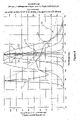
- Figure 4 shows the spectrum of light that is emitted by different light sources comprising an LED light source for emitting white light at correlated color temperature (CCT) of 6500 K, a low pressure sodium lamp, a monochromatic amber LED light unit configured to emit amber light and a phosphor converted LED light unit configured to emit amber light.
- the phosphor converted LED light unit configured to emit amber light may be referred to as phosphor converted amber LED light unit.
- Curve C1 of Figure 4 shows the spectrum of light emitted by an LED light source for emitting white light at correlated color temperature (CCT) of 6500 K.
- Curve C2 of Figure 4 shows the spectrum of light emitted by a monochromatic amber LED light unit configured to emit amber light.
- Curve C3 of Figure 4 shows the spectrum of a phosphor converted LED light unit configured to emit amber light.
- Curve C4 of Figure 4 shows the spectrum of a low pressure sodium light unit, which is an example of a sodium vapor lamp light unit.
- Curve C5 of Figure 4 shows a luminosity function indicating the average spectral sensitivity of human visual perception of brightness for different wavelengths. The luminosity function may be referred to as luminous efficiency function or as V-Lambda-Curve.
- Curve C6 of Figure 4 shows the reflection probability of light-reflection on water drops of light for different wavelengths.
- the horizontal axis (x-axis) of the graph of Figure 4 corresponds to the wavelength in nanometers (nm).
- the vertical axis (y-axis) of the graph of Figure 4 corresponds to the relative emission intensity.
- the vertical axis of the graph of Figure 4 corresponds to the average spectral sensitivity of human visual perception of brightness.
- the vertical axis of the graph of Figure 4 corresponds to the reflection probability of light-reflection on water drops respectively the scattering probability of light-scattering (normalized to a wavelength of 460 nm).
- the reflection probability of light-reflection on water drops and the scattering probability of light-scattering on water drops are direct proportional. That is, the higher the reflection probability of light-reflection on water drops the higher the scattering probability of light-scattering on water drops and vice versa. Therefore, the embodiments of the present invention may alternatively use, instead of the reflection probability of light-reflection on water drops, the scattering probability of light-scattering on water drops as a value for controlling light emission of the at least one LED-LS by the control unit of the lighting system.
- control unit may be configured to control the light emission of the at least one LED-LS based on moisture information on the moisture at an area such that, in case the moisture information fulfills a condition regarding the moisture in the area, the control unit controls the at least one LED-LS to emit only light of a spectrum comprising a scattering probability of light-scattering on water drops smaller than a probability threshold.
- the spectrum of the LED light source for emitting white light may comprise its 20% (0.2) relative emission intensity at about 430 nm (nanometers) and about 670 nm.
- the spectrum of the monochromatic amber LED light unit (cf. curve C2) may comprise its 20% (0.2) relative emission intensity at 580 nm and 605 nm.
- the spectrum of the phosphor converted LED light unit configured to emit amber light (cf. curve C3) may comprise its 20% (0.2) relative emission intensity at 542 nm and 670 nm.
- the reflection probability of light-reflection is greater for the peak wavelength of the spectrum of the white light shown by curve C1 than for the peak wavelength of the spectrum of the monochromatic amber LED light unit shown by curve C2.
- the peak wavelength of a spectrum corresponds to the wavelength at which the relative emission intensity of the spectrum is 100% (1).
- the reflection probability of light-reflection is similar, in particular the same, for the peak wavelength of the spectrum of the monochromatic amber LED light unit shown by curve C2 and the peak wavelength of the spectrum of the phosphor converted LED light unit configured to emit amber light shown by curve C3.
- the spectrum of the low pressure sodium light unit (cf. curve C4) is best with regard to the reflection-probability of light-reflection on water drops of the emitted light compared to the spectrum of the monochromatic amber LED light unit and the spectrum of the phosphor converted LED light unit configured to emit amber light.
- the width of the spectrum of the low pressure sodium light unit is smallest.
- the spectrum of the monochromatic amber LED light unit is better with regard to the reflection-probability of light-reflection on water drops of the emitted light compared to the spectrum of the phosphor converted LED light unit configured to emit amber light.
- the width of the spectrum of the monochromatic amber LED light unit (cf.
- curve C2 is smaller than the width of the spectrum of the phosphor converted LED light unit (cf. curve C3). Nevertheless, as shown by curve C5, indicating the average spectral sensitivity of human visual perception of brightness for different wavelengths, although the spectrum of the phosphor converted LED light unit is wider than the spectrum of the monochromatic amber LED light unit and the low pressure sodium light unit, the phosphor converted amber LED light unit may be used for implementing the at least one LED-LS of the lighting system, in particular the second LED unit of the at least one LED-LS.
- the at least one LED-LS of the lighting system preferably comprises or corresponds to a monochromatic amber LED light unit configured to emit amber light or a phosphor converted LED light unit configured to emit amber light.
- the second LED unit of the at least one LED-LS of the lighting system may be a monochromatic amber LED light unit configured to emit amber light or a phosphor converted LED light unit configured to emit amber light.
- Figure 5 shows an example of a relationship between a reflection probability of light-reflection on water drops of light and the wavelength of light according to an embodiment of the invention.
- the reflection probability of light-reflection on water drops of emitted light is indicated by a relative scattering coefficient. Therefore, the greater the relative scattering coefficient of a wavelength of light, the greater the reflection probability of light-reflection on water drops of light at that wavelength.
- the relative scattering coefficient is in particular a relative Raleigh scattering coefficient.
- Figure 5 indicates an example of a possible probability threshold in terms of a threshold T1 for the relative scattering coefficient.
- the at least one LED-Ls of the lighting system is configured to emit white light of e.g. a CCT of 6500 K and, thus, light of a spectrum between 430 nm and 670 nm, in particular between 430 nm and 650 nm or 415 nm and 665 nm.
- the threshold T1 corresponds to the value of the relative scattering coefficient for the wavelength equaling to 540 nm (indicated by the dashed line in Figure 5 ).
- the control unit of the lighting system is configured to control the light emission of the at least one LED-LS such that, in case the moisture information fulfills the condition regarding the moisture in the area, the control unit controls the at least one LED-LS to emit only light of a spectrum comprising wavelengths greater than 540 nm.
- the control unit controls the at least one LED-LS to emit only light of a spectrum comprising wavelengths greater than 540 nm to emit only light of a spectrum comprising a reflection probability of light reflection on water drops smaller than the probability threshold indicated by the threshold T1.
- the at least one LED-LS may comprise or correspond to a monochromatic amber LED light unit configured to emit amber light or a phosphor converted LED light unit configured to emit amber light.
- a monochromatic amber LED light unit may be configured to emit light of a spectrum comprising a relative emission intensity greater than 20% between a wavelength of 580 nm and a wavelength of 605 nm.
- a monochromatic amber LED light unit may be configured to emit light of a spectrum comprising 20% relative emission intensity at a wavelength of 580 nm and a wavelength of 605 nm.
- a monochromatic amber LED light unit may be configured to emit light of a spectrum between a wavelength of 565 nm and a wavelength of 620 nm.
- a phosphor converted amber LED light unit may be configured to emit light of a spectrum comprising a relative emission intensity greater than 20% between a wavelength of 542 nm and a wavelength of 670 nm.
- a phosphor converted amber LED light unit may be configured to emit light of a spectrum comprising 20% relative emission intensity at a wavelength of 542 nm and a wavelength of 670 nm.
- a phosphor converted amber LED light unit may be configured to emit light of a spectrum between a wavelength of 527 nm and a wavelength of 685 nm.
- the threshold T1 may be moved to the relative scattering coefficient at a wavelength of e.g. 525 nm.
- the relative scattering coefficient is only slightly greater for the wavelength 525 nm compared to the wavelength 540 nm.
- the reflection probability of light-reflection on water drops of the emitted light may be still acceptable for reducing blinding.
- Figure 6 schematically shows a lighting system according to an embodiment of the present invention.
- Figure 6 shows an example of an embodiment according to which the lighting system comprises three or more street luminaires L1, L2, L3 for lighting a street.
- the above description of the lighting system of the first aspect and Figures 1 (a), 1(b) , 2 and 3 is correspondingly valid for the lighting system of Figure 6 , wherein the three street luminaires L1, L2, L3 correspond to three LED-LS of the system.
- the above description of the lighting system of the first aspect and Figures 1 (a), 1(b) , 2 and 3 is correspondingly valid for each of the luminaires L1, L2, L3, wherein the respective luminaire corresponds to the lighting system.
- each of the luminaires L1, L2, L3 is configured to wirelessly receive information, in particular moisture information regarding the moisture of the street area, from a local weather station 61, a mobile end device of a person 62 present at the street area, a vehicle 63 driving at the street area and the other luminaires.
- the moisture information regarding moisture of the street area may be locally generate by the lighting system.
- the moisture information may be generated by one or more sensors of at least one of the luminaires L1, L2, L3 and/or by one or more sensors of the lighting system arranged extern to the luminaires L1, L2, L3.
- the locally generated moisture information may be provided to each of the luminaires L1, L2, L3 from either one or more other luminaires L3 and/or an optional central control unit of the lighting system.
- the moisture information may be provided within the lighting network comprising the three luminaires L1, L2, L3.
- the moisture information may be provided from outside the lighting system, in particular from a data network.
- the moisture information may be provided to an optional central control unit of the lighting system and/or to at least one of the luminaires L1, L2, L3, in particular each of the luminaires L1, L2, L3, from a weather forecast station.
- the above description is not limited to a street area and thus, street luminaires, but is also valid for any area to be illuminated by a lighting system, wherein the lighting system may comprise any type of luminaire or may correspond to any type of luminaire.
Landscapes
- Circuit Arrangement For Electric Light Sources In General (AREA)
Abstract
Description
- The present invention relates to a lighting system and a method for providing light to an area. According to an embodiment of the invention, the lighting system corresponds to a luminaire. According to a further embodiment of the invention, the lighting system comprises two or more luminaires.
- In the prior art, LED light sources (LED-LS, light emitting diode light sources) comprising one or more LEDs (light emitting diodes), such as one or more of organic LEDs, inorganic LEDs, LEDs with secondary emission etc., are well known. LED light sources are more and more used instead of more traditional light sources comprising or corresponding to filament lamps and/or gas-discharge lamps. The use of LEDs for providing light has many advantages such as reduced energy consumption, longer lifetime, lighting of variable color etc.
- In particular, LED light sources configured to emit white light are used for lighting purposes. Such LED light sources may emit light of a spectrum that causes more blinding (of persons) compared to more traditional light sources in case of humid air, because the white light emitted by the LED light sources is more reflected by the humid air compared to the light emitted by a traditional light source, such as a gas discharge lamp. For example in the field of street lighting before the use of LED light sources sodium vapor lamps, such as low pressure sodium lamps, were used as light sources. A light source emitting white light (e.g. of correlated color temperature (CCT) of 6500 K) causes more blinding in case of rain or fog compared to a sodium vapor lamp. This is due to an increased light-reflection of the light emitted by the LED light source on water drops, present due to the rain or fog, compared to the light-reflection om water drops of the light emitted by a sodium vapor lamp in such a case. The terms "dazzle" and "glare" may be used as synonyms for the term "blinding".
- Therefore, it is an object of the present invention to provide an improved lighting system using an LED light source for providing light to an area, e.g. a street area, both in dry and wet conditions. In particular, it is an object to provide a lighting system using an LED light source for providing light to an area, for which the above described drawbacks in case of moisture (e.g. humid air and/or wet ground) are reduced, in particular overcome.
- These and other objects, which become apparent upon reading the following description, are solved by the subject-matter of the independent claim. The dependent claims refer to preferred embodiments of the invention.
- The terms "preferably", "in particular" and "optionally" are used herein for introducing optional features of the present invention.
- According to a first aspect of the invention a lighting system for providing light to an area is provided. The system comprises at least one LED light source (LED-LS) configured to emit white light, and a control unit configured to control a light emission of the at least one LED-LS. The control unit is configured to control the light emission of the at least one LED-LS based on moisture information on a moisture in the area such that, in case the moisture information fulfills a condition regarding the moisture in the area, the control unit controls the at least one LED-LS to emit only light of a spectrum comprising a reflection probability of light-reflection on water drops smaller than a probability threshold.
- In other words, in case the moisture information fulfills the condition regarding the moisture in the area, the control unit is configured to control the light emission of white light of the at least one LED-LS such that, when the at least one LED-LS emits light (light emitting state of the at least one LED-LS), the at least one LED-LS stops emitting light of a spectrum comprising a reflection probability of light-reflection on water drops greater than or equal to the probability threshold. That is, in case the moisture information fulfills the condition, the control unit is configured to control the light emission of the at least one LED-LS such that the control unit controls the at least one LED-LS to emit light of one or more wavelengths for which the reflection probability of light-reflection on water drops is smaller than the probability threshold.
- Therefore, the lighting system may provide white light to the area in case the moisture information does not fulfill the condition. This is advantageous, because an LED-LS providing white light for illumination has a good efficiency factor with regard to the electrical energy needed for providing the lighting in the area. On the other side, in case the moisture information fulfills the condition, e.g. the air in the area comprises a certain humidity level, the lighting system may switch from providing white light to only providing light of the spectrum comprising a reflection probability of light-reflection on water drops smaller than the probability threshold, for providing the lighting in the area. This is advantageous, because this reduces the blinding (of a person in the area) caused by the light emission compared to a case, in which the light emission is not changed and, thus, emission of white light is continued. Reducing the blinding increases the visibility for a person present in the area.
- Emitting only light of the spectrum comprising a reflection probability of light-reflection on water drops smaller than the probability threshold may decrease the efficiency factor of the light emission by the lighting system. Therefore, the control unit is configured to change the light emission of white light to light of the spectrum comprising a reflection probability of light-reflection on water drops smaller than the probability threshold only in case the condition is fulfilled. Thus, in case the condition is not fulfilled, the white light with the good efficiency factor is emitted.
- In the light of the above, the lighting system according to the first aspect is advantageous, because it allows reducing blinding caused by light emission of the LED-LS of the system in case the condition regarding the moisture in the area, e.g. a certain moisture level or presence of rain or fog, is fulfilled. At the same time, the lighting system allows to improve the efficiency of the light emission by allowing white light emission, in case the condition is not fulfilled (e.g. good weather, no rain, no fog).
- The moisture in the area comprises the moisture of the ground in the area and the moisture of the air in the area. The term humidity is used for referring to the moisture in the air of the area. The term "moisture" is to be understood as referring to water in the form of drops (i.e. water drops) either in the air, in a substance or on a surface (e.g. the ground in the area).
- In particular, the smaller the wavelength of the emitted light the higher the reflection probability of light-reflection on water drops of the emitted light.
- The area maybe an outdoor area, e.g. a street area, a harbor/port area, airport area, forest area etc. Alternatively, the area maybe an indoor area, e.g. indoor skiing hall, indoor pool, thermal bath etc. In particular, the area may be a combination of an outdoor and indoor area, such as a sports stadium or swimming hall, optionally with a movable roof.
- The LED-LS may comprise a plurality of LEDs (light emitting diodes), such as at least one of organic LEDs, inorganic LEDs, LEDs with secondary emission etc.
- The control unit may comprise or correspond to a processor, a microprocessor, a controller, a microcontroller, a field programmable gate array (FPGA), an application specific integrated circuit (ASIC) or any combination of them.
- In particular, the moisture information fulfills the condition in case the moisture information informs on a humidity level greater than a humidity threshold. Alternatively or additionally, the moisture information may fulfill the condition in case the moisture information informs on precipitation and/or fog. In particular, the moisture information may fulfill the condition in case the moisture information informs on a precipitation intensity greater than an intensity threshold, i.e. on an amount of precipitation greater than a threshold amount. Alternatively or additionally, the moisture information may fulfill the condition in case the moisture information informs on a moisture level of the ground in the area greater than a moisture threshold.
- Thus, the moisture information may inform on at least one of a presence of a weather condition comprising or corresponding to precipitation and/or fog; a degree of a weather condition comprising or corresponding to precipitation and/or fog; a humidity level; and a moisture level of the ground.
- The humidity level may correspond to the absolute humidity in the area, i.e. the total mass of water vapor present in a given volume or mass of air. The humidity level may correspond to a relative humidity. Precipitation may comprise or correspond to rain, snow, sleet, hail etc. The moisture level may correspond to an absolute moisture level or a relative moisture level.
- In particular, the lighting system comprises a weather condition sensor unit configured to detect precipitation and/or fog in the area and provide the detection result as the moisture information to the control unit. The weather condition sensor unit may comprise or correspond to a precipitation and/or fog sensor unit. Additionally or alternatively, the lighting system may comprise a humidity sensor unit configured to detect a humidity level of the humidity in the area and provide the detection result as the moisture information to the control unit. Additionally or alternatively, the lighting system may comprise a moisture sensor unit configured to detect a moisture level of the ground in the area and provide the detection result as the moisture information to the control unit. Additionally or alternatively, the lighting system may comprise a communication unit configured to receive the moisture information, e.g. from a weather forecast station, and provide the moisture information to the control unit.
- The weather condition unit may be configured to detect the presence of precipitation and/or fog in the area and optionally the degree of precipitation (i.e. amount/intensity of precipitation) and/or fog (density of fog). For implementing a weather condition sensor unit, a precipitation and/or fog sensor unit, a humidity sensor unit and a moisture sensor unit any sensors known in the art may be used.
- The communication unit may be configured to communicate wirelessly and/or wire-bound for receiving the moisture information. In particular, the communication unit may be configured to communicate with a weather forecast station for receiving information on the weather condition in the area as the moisture information. The communication unit may be a part of the control unit. In particular, the wireless communication unit maybe configured to communicate wirelessly using radio waves. The communication unit may be implemented by any means known in the art.
- Thus, the lighting system may generate the moisture information regarding the moisture in the area by itself using at least one of a weather condition unit, precipitation and/or fog sensor unit, a humidity sensor unit and a moisture sensor unit. In this case, the control unit may be configured to determine based on the generated moisture information that the condition regarding the moisture in the area is fulfilled, e.g. presence of precipitation, the humidity level in the area is greater than a humidity threshold and/or the moisture level of the ground is greater than a moisture threshold. The control unit may react thereto, by controlling the light emission of the at least one LED light source such that the light emission is changed from a first emission state to a second emission state. In the first emission state, the at least one LED-LS emits white light, when the control unit controls the at least one LED-LS to emit light. In the second emission state, the at least one LED-LS emits only light of the spectrum comprising a reflection probability of light-reflection on water drops smaller than the probability threshold.
- For example, in case the moisture information informs on a moisture level of the ground in the area greater than a moisture threshold (e.g. wet street due to rainfall), the control unit may determine that that the condition is fulfilled.
- In addition or alternatively, the system may receive the moisture information regarding the moisture in the area from a weather forecast station. Thus, the control unit may already react to a received moisture information fulfilling the condition before the condition is actually fulfilled in the area. For example, in case, the communication unit receives from the weather forecast station information informing on heavy rain fall for a certain time and optionally date, e.g. on 12.05.2020 at 12.00 o'clock, and the condition corresponds to such heavy rain fall, then the control unit may determine based on the received information from the weather forecast station that at that time and optionally date (e.g. 12.05.2020 at 12.00 o'clock), the condition regarding the moisture in the area will be fulfilled. The control unit may be configured to control the at least one LED-LS such that at that time and optionally date (12.05.2020 at 12.00 o'clock) the at least one LED-LS emits only light of the spectrum comprising a reflection probability of light-reflection on water drops smaller than the probability threshold.
- Optionally, the control unit may be configured to control the at least one LED-LS such that already a time period (e.g. 30 minutes) before that time and optionally date (12.05.2020 at 12.00 o'clock) the at least one LED-LS emits only light of the spectrum comprising a reflection probability of light-reflection on water drops smaller than the probability threshold. Thus, the communication unit allows the control unit to react to the condition already before the condition is fulfilled.
- For evaluating the moisture information received from one or more sensors of the lighting system, such as the aforementioned sensors, and/or the information received from a weather forecast station, the control unit may use one or more look-up tables and/or one or more algorithms.
- The reflection probability of light-reflection on water drops may correspond to a relative scattering coefficient and the probability threshold may correspond to a threshold for the relative scattering coefficient.
- In particular, the reflection probability of light-reflection on water drops may correspond to a relative Rayleigh scattering coefficient and the probability threshold may correspond to a threshold for the relative Rayleigh scattering coefficient. In other words, the relative scattering coefficient may be a relative Rayleigh scattering coefficient.
- In particular, the higher the relative scattering coefficient the higher the reflection probability of light-reflection on water drops.
- In particular, the at least one LED-LS comprises a first LED unit configured to emit the white light, and a second LED unit configured to emit light of a spectrum comprising a reflection probability of light-reflection on water drops smaller than the probability threshold. The control unit may be configured to control the light emission of the at least one LED-LS such that the first LED unit emits light, in case the moisture information does not fulfill the condition, and only the second LED unit emits light, in case the moisture information fulfills the condition.
- In particular, the control unit may be configured to control the light emission of the at least one LED-LS such that only the first LED unit emits light, in case the moisture information does not fulfill the condition.
- The first LED unit and the second LED unit each may correspond to an LED chip.
- In particular, the second LED unit is configured to emit light of a spectrum comprising a relative emission intensity greater than 20% between a wavelength of 580 nm and a wavelength of 605 nm. In other words, the second LED unit may be configured to emit light of a spectrum comprising, between the wavelength of 580 nm and the wavelength of 605 nm, a relative emission intensity between 20% and 100%. That is, the relative emission intensity of the spectrum may be equal to 100% at a wavelength between the wavelength of 580 nm and the wavelength of 605 nm. Thus, the second LED unit may be configured to emit light of a spectrum comprising its main part (i.e. the main part of the spectrum) between the wavelength of 580 nm and the wavelength of 605 nm. The second LED unit may be configured to emit light of a spectrum comprising 20% relative emission intensity at the wavelength of 580 nm and the wavelength of 605 nm. Alternatively, the second LED unit may be configured to emit light of a spectrum comprising a relative emission intensity greater than 20% between a wavelength of 542 nm and a wavelength of 670 nm. In other words, the second LED unit may be configured to emit light of a spectrum comprising, between the wavelength of 542 nm and the wavelength of 670 nm, a relative emission intensity between 20% and 100%. That is, the relative emission intensity of the spectrum may be equal to 100% at a wavelength between the wavelength of 542 nm and the wavelength of 670 nm. Thus, the second LED unit may be configured to emit light of a spectrum comprising its main part (i.e. the main part of the spectrum) between the wavelength of 542 nm and the wavelength of 670 nm. The second LED unit may be configured to emit light of a spectrum comprising 20% relative emission intensity at the wavelength of 542 nm and the wavelength of 670 nm. The second LED unit may be configured to emit light of a spectrum between a wavelength of 565 nm and a wavelength of 620 nm or a wavelength of 527 nm and a wavelength of 685 nm.
- In particular, the spectrum comprises a Gaussian spectral shape. The spectrum may be a symmetrical spectrum.
- The second LED unit may be a monochromatic amber LED unit configured to emit amber light. The second LED unit may be a phosphor converted LED unit configured to emit amber light.
- In particular, the first LED unit is configured to emit white light with a variable correlated color temperature (CCT) and the control unit is configured to vary the CCT of the white light.
- The first LED unit may be configured to emit white light with a variable CCT between 2700 and 4000 K. Optionally, the first LED unit may be configured to emit white light with a CCT of 6500 K.
- In particular, the lighting system comprises a lens unit arranged to modulate the light emitted by the second LED unit. The lens unit comprises an improved beam geometry reducing the reflection probability of light-reflection on water drops of the light emitted by the second LED unit.
- For implementing the lens unit any lens known in the art may be used. The lens unit may correspond to a lens arrangement comprising a plurality of lenses.
- In particular, the lens unit is arranged to reduce reflectivity of light, emitted by the second LED unit, on a wet ground in the area. That is, the lens unit may be arranged to reduce reflectivity of light, emitted by the second LED unit, on a ground in the area, wherein the moisture level of the ground is above a moisture threshold (e.g. a water level or water amount above a threshold value is present on the ground).
- According to an embodiment, the lighting system is a luminaire.
- The lighting system may be an outdoor luminaire, such as a street lighting luminaire, a harbor lighting luminaire, a floodlight luminaire (e.g. for a sports stadium), a spotlight luminaire (e.g. for a sports stadium), a car headlights luminaire etc.
- The at least one LED-LS may correspond to at least one LED module, the luminaire may comprise a driver module for driving the at least one LED module, and the driver module may comprise the control unit. Alternatively, the control unit may be extern to the driver module (i.e. not a part of the driver module).
- In particular, the luminaire may comprise a housing and the at least one LED-LS (LED module), the driver module and the control unit may be arranged inside the housing. In this case, the at least one LED-LS (LED module ) is arranged in the housing such that the at least one LED-LS (LED module) is configured to emit light from inside the housing via an opening and/or a transparent section of the housing to the outside of the housing.
- The driver module is configured to provide the at least one LED-LS (LED module) with electrical energy. For this, the driver module may comprise an optional power factor correction (PFC) circuit, a power conversion circuit (AC/DC and/or DC/DC power conversions circuit) and/or an optional filter circuit. The power conversion circuit may comprise one or more actively switched power converters (in particular at least one actively switched DC/DC power converter and/or at least one actively switched AC/DC power converter). The control unit is configured to control the light emission of the at least one LED-LS (LED module) by controlling the electrically energy supplied by the driver module to the at least one LED-LS (LED module). In particular, in case the driver module comprises an actively switched power converter (may be referred to as active power converter), such as at least one boost converter, buck converter, flyback converter and/or resonant converter, the control unit may be configured to control switching of the actively switched power converter for controlling the electrical energy supplied to the at least one LED-LS (LED module) and, thus, the light emission by the at least one LED-LS (LED module). The higher the electrical energy (e.g. time-averaged electrical energy over a time period), in particular current (e.g. time-averaged current over a time period), supplied to the at least one LED-LS (LED module), the higher the amount of light respectively the higher the light intensity of the light emitted by the at least one LED-LS (LED module).
- According to a further embodiment, the lighting system comprises two or more LED-LS and each LED-LS is a luminaire.
- Each LED-LS may be an outdoor luminaire, such as a street lighting luminaire, a harbor lighting luminaire, a floodlight luminaire, a spotlight luminaire, e.g. for a sports stadium, car headlights luminaire etc.
- The above description of the lighting system maybe valid for each luminaire of the lighting system, in case the lighting system comprises two or more LED-LS and each LED-LS is a luminaire.
- At least one of the two or more LED-LS comprises a local control unit configured to control the light emission of the respective LED-LS based on moisture information on the moisture in the area such that in case the moisture information fulfills the condition regarding the moisture in the area, the local control unit controls the respective LED-LS to emit only light of a spectrum comprising a reflection probability of light-reflection on water drops smaller than the probability threshold. In particular, each of the two or more LED-LS comprises a local control unit configured to control the light emission of the respective LED-LS based on moisture information on the moisture in the area such that in case the moisture information fulfills the condition regarding the moisture in the area, the local control unit controls the respective LED-LS to emit only light of a spectrum comprising a reflection probability of light-reflection on water drops smaller than the probability threshold. In addition or alternatively, the control unit may be part of one of the two or more LED-LS and may be configured to control the light emission of the two or more LED-LS.
- In the following, the two or more LED-LS of the lighting system according to the further embodiment maybe referred to two or more luminaires, because each LED-LS of the lighting system according to the further embodiment is a luminaire.
- The light emission by each of the two or more luminaires of the lighting system of the further embodiment may be controlled according to different alternatives in dependence of the moisture in the area. According to a first alternative, the control unit of the system may be a single central control unit that is configured to control the light emission of the two or more luminaires based on moisture information on the moisture in the area such that, in case the moisture information fulfills the condition regarding the moisture in the area, the control unit controls the two or more luminaires to emit only light of a spectrum comprising a reflection probability of light-reflection on water drops smaller than a probability threshold.
- According to a second alternative, the control unit of the system may be part of one of the two or more luminaires and may be configured to control the light emission of the two or more luminaires based on moisture information on the moisture in the area such that, in case the moisture information fulfills the condition regarding the moisture in the area, the control unit controls the two or more luminaires to emit only light of a spectrum comprising a reflection probability of light-reflection on water drops smaller than a probability threshold.
- According to a third alternative, in addition to the first alternative at least one of the two or more luminaires may comprise a local control unit configured to control the light emission of the respective luminaires based on moisture information on the moisture in the area such that in case the moisture information fulfills the condition regarding the moisture in the area, the local control unit controls the respective luminaire to emit only light of a spectrum comprising a reflection probability of light-reflection on water drops smaller than the probability threshold.
- According to a fourth alternative, in addition to the first alternative each of the two or more luminaires may comprise a local control unit configured to control the light emission of the respective luminaire based on moisture information on the moisture in the area such that in case the moisture information fulfills the condition regarding the moisture in the area, the local control unit controls the respective luminaire to emit only light of a spectrum comprising a reflection probability of light-reflection on water drops smaller than the probability threshold.
- A fifth alternative corresponds to the third alternative, wherein the control unit of the system corresponds to the local control unit of the at least one luminaire of the two or more luminaires. A sixth alternative corresponds to the fourth alternative, wherein the control unit of the system corresponds to a local control unit of one of the two or more luminaires.
- The above description with respect to the control unit of the lighting system may be valid for the local control unit of a respective luminaire.
- Each LED-LS (luminaire) may comprise a communication unit for communicating, in particular wirelessly, with other devices. The other devices may comprise or correspond to the other LED-LS of the lighting system. Additionally or alternatively, other devices may correspond to mobile end devices, such as mobile phones, vehicles, local weather stations, weather forecast stations etc. For example, in case the lighting system is used for providing illumination to a street area, the communication unit of each LED-LS (luminaire) may be configured to communicate with vehicles driving on a street at the street area, mobile end devices carried by persons walking on a pedestrian at the street area and a local weather station that may be present at the street area for monitoring the weather condition at the street area. In particular, the local weather station may be configured to detect the humidity level in the street area, the moisture level of the ground in the street area (e.g. moisture level of the street) and/or the presence and optionally amount of precipitation and/or fog in the street area. Thus, the communication unit of each LED-LS (luminaire) may be configured to receive moisture information regarding the moisture at the street area from the vehicles, mobile end devices and the local weather station. The communication between each of the LED-LS (luminaires) and other devices maybe wireless. The wireless communication may be based on radio waves.
- The above is also valid with respect to a different outdoor area, such as a harbor, airport etc. For example, in case of the harbor the communication unit may be configured to communicate with ships and, thus, the communication unit of each LED-LS (luminaire) may be configured to receive moisture information regarding the moisture at the harbor area from the ships.
- In particular, the first LED unit and the second LED unit form an LED module.
- As described above, according to an embodiment the lighting system may be a luminaire. In this case, the at least one LED-LS corresponds to the lighting means of that luminaire. According to a further embodiment, the lighting system may comprise at least two LED-LS, wherein each LED-LS corresponds to a luminaire. In this case, each luminaire comprises lighting means. The description of the lighting system being a luminaire according to the above-mentioned embodiment is correspondingly valid for describing each luminaire of the system according to the further embodiment.
- In order to achieve the lighting system according to the present invention, some or all of the above described optional features may be combined with each other.
- According to a second aspect of the invention, a method for providing light to an area is provided, wherein the method comprises the step of emitting, by at least one LED light source, LED-LS, white light. The method further comprises the step of controlling, by a control unit, a light emission of the at least one LED-LS based on moisture information on a moisture in the area such that in case the moisture information fulfills a condition regarding the moisture in the area, the control unit controls the at least one LED-LS to emit only light of a spectrum comprising a reflection probability of light-reflection on water drops smaller than a probability threshold.
- The method according to the second aspect of the present invention achieves the same advantages as the lighting system according to the first aspect of the invention.
- The above description with regard to the lighting system according to the first aspect of the present invention is correspondingly valid for the method according to the second aspect of the present invention.
- In particular, the above description of the LED-LS and control unit of the lighting system according to the first aspect of the present invention is correspondingly valid for the LED-LS and control unit used for performing the method according to the second aspect of the present invention.
- In the following, the invention is described exemplarily with reference to the enclosed figures, wherein
- Figure 1 (a)
- schematically shows a lighting system according to the first aspect of the present invention;
- Figure 1 (b)
- schematically shows a lighting system according to an embodiment of the present invention;
- Figure 2
- schematically shows a lighting system according to an embodiment of the present invention;
- Figure 3
- schematically shows a lighting system according to an embodiment of the present invention;
- Figure 4
- shows the spectrum of light that is emitted by different light sources comprising an LED light source for emitting white light at correlated color temperature (CCT) of 6500 K, a low pressure sodium lamp, a monochromatic amber LED light unit configured to emit amber light and a phosphor converted LED light unit configured to emit amber light;
- Figure 5
- shows an example of a relationship between a reflection probability of light-reflection on water drops and wavelength of light according to an embodiment of the invention;
- Figure 6
- schematically shows a lighting system according to an embodiment of the present invention.
- In the Figures, corresponding elements have the same reference signs. The proportions and dimensions of the elements shown in the figures do not represent the luminaire to scale, but are merely chosen to describe the structure and function of the luminaire.
-
Figure 1 (a) schematically shows a lighting system according to the first aspect of the present invention. - As shown in
Figure 1 (a) , thelighting system 1 for providing light to an area comprises an LED light source (LED-LS) 2 and acontrol unit 3. Thelighting system 1 may comprise more than one LED-LS 2. The at least one LED-LS 2 is configured to emit white light and thecontrol unit 3 is configured to control a light emission of the at least one LED-LS 2. Thecontrol unit 3 is configured to control the light emission of the at least one LED-LS 2 based on moisture information on a moisture in the area such that, in case the moisture information fulfills a condition regarding the moisture in the area (e.g. rain present in the area), thecontrol unit 3 controls the at least one LED-LS 2 to emit only light of a spectrum comprising a reflection probability of light-reflection on water drops smaller than a probability threshold. - Therefore, the
lighting system 1 ofFigure 1 (a) may reduce blinding of persons present in the area that is caused by the light emission of the at least one LED-LS 2, in case the condition regarding the moisture in the area is fulfilled (e.g. rain present in the area). Namely, the light of the spectrum comprising a reflection probability of light-reflection on water drops smaller than a probability threshold is less reflected on water drops, such as rain drops, compared to light of wavelengths respectively a spectrum comprising a reflection probability of light-reflection on water drops greater than or equal to the probability threshold. Generally, the higher the reflection probability of light-reflection on water drops of a wavelength of light the more probable the light of said wavelength and, thus, the more often the light of said wavelength is reflected on water drops, such as rain drops. Reducing blinding increases the visibility of a person present in the area. - In particular, the smaller the wavelength of emitted light the higher the reflection probability of light-reflection on water drops of that emitted light.
- For describing the
system 1 ofFigure 1 (a) in more detail, reference is made to the above description of the lighting system according to the first aspect of the present invention. -
Figure 1 (b) schematically shows a lighting system according to an embodiment of the present invention. The lighting system ofFigure 1 (b) corresponds to the lighting system ofFigure 1 (a) . Therefore, the above description of the system ofFigure 1 (a) is also valid for the lighting system ofFigure 1 (b) and in the following mainly additional features shown inFigure 1 (b) are described. - As shown in
Figure 1 (b) the at least one LED-LS 2 may optionally comprise afirst LED unit 4a configured to emit white light, and asecond LED unit 4b configured to emit light of the spectrum comprising a reflection probability of light-reflection on water drops smaller than the probability threshold. Thecontrol unit 3 may be configured to control the light emission of the at least one LED-LS 2 such that thefirst LED unit 4a emits light, in case the moisture information does not fulfill the condition, and only thesecond LED unit 4b emits light, in case the moisture information fulfills the condition. - For a more detailed description of the
first LED unit 4a and thesecond LED unit 4b reference is made to the above description of the first LED unit and second LED unit of the lighting system according to the first aspect of the present invention. -
Figure 2 schematically shows a lighting system according to an embodiment of the present invention. The lighting system ofFigure 2 corresponds to the lighting system ofFigure 1(b) . Therefore, the above description of the lighting system ofFigures 1(a) and 1(b) is also valid for the lighting system ofFigure 2 and in the following mainly additional features shown inFigure 2 are described. - As shown in
Figure 2 thelighting system 1 may comprise an optional weathercondition sensor unit 5a configured to detect precipitation and/or fog in the area and provide the detection result as the moisture information to thecontrol unit 3. The optional weathercondition sensor unit 5a may be a precipitation and/or fog sensor unit. Additionally or alternatively, thelighting system 1 may comprise ahumidity sensor unit 5b configured to detect a humidity level of the humidity in the area and provide the detection result as the moisture information to thecontrol unit 3. Additionally or alternatively, thelighting system 1 may comprise amoisture sensor unit 5c configured to detect a moisture level of the ground of the area and provide the detection result as the moisture information to thecontrol unit 3. Additionally or alternatively, thelighting system 1 may comprise a communication unit 6 configured to receive the moisture information, e.g. from a weather forecast station, and provide the moisture information to thecontrol unit 3. The communication unit 6 may be configured for a wireless and/or wire-bound communication with outside thelighting system 1, e.g. with a weather forecast station. The wireless communication may be based on radio waves. - The
lighting system 1 may comprise an optional bus (not shown inFigure 2 ), such as a DALI (Digital Addressable Lighting Interface) bus or DALI-2 bus, to which thecontrol unit 3, the optional weathercondition sensor unit 5a, the optionalhumidity sensor unit 5b, the optionalmoisture sensor unit 5c and the optional communication unit 6 are electrically connected allowing communication between the electrical components connected to the bus. Thus, theoptional sensor units control unit 3. Thecontrol unit 3 may be configured to control electrical components, which are connected to the bus, via the bus. DALI (DALI Version 1) and DALI-2 (DALI Version 2) are industry standards that are well known in the field of lighting. Preferably, the at least one LED-LS 2 may be electrically connected to the bus. This may be in particular the case, when thelighting system 1 is a luminaire. - The
lighting system 1 may comprise additional sensor units, such as a temperature sensor unit, light sensor unit, ambient light sensor unit, presence and/or movement detector unit etc., that are configured to provide information to thecontrol unit 3 for controlling the light emission of the at least one LED-LS 2. Such additional sensor units may be connected to the optional bus of thelighting system 1. - In case the
lighting system 1 is a luminaire, thecontrol unit 3 may be part of a driver module 7 for driving the at least one LED-LS 2, as indicated inFigure 2 by a dashed box. The driver module 7 may be connected to the optional bus of theluminaire 1. Thecontrol unit 3 may alternatively be an electrical component separate to the driver module 7 that is electrically connected with the driver module 7, optionally via the optional bus. In case thelighting system 1 is a luminaire, the at least one LED-LS 2 is the lighting means of theluminaire 1 and the at least one LED-LS 2 may correspond to at least one LED module. The optional weathercondition sensor unit 5a, the optionalhumidity sensor unit 5b, the optionalmoisture sensor unit 5c, the optional communication unit 6 and/or optional additional sensor units may be connected, in particular detachably connected, to the driver module 7 for providing information respectively data to thecontrol unit 3 for the control of the light emission of the LED-LS 2 by thecontrol unit 3. For this, the driver module 7 may comprise one or more Zhaga interfaces (e.g. Zhaga sockets) and/or NEMA interfaces (e.g. NEMA sockets) that are well known in the art. - For a more detailed description of the optional weather
condition sensor unit 5a, the optionalhumidity sensor unit 5b, the optionalmoisture sensor unit 5c and the optional communication unit 6 of the system according toFigure 2 , reference is made to the above description of the optional weather condition sensor unit, the optional humidity sensor unit, the optional moisture sensor unit and the optional communication unit of the lighting system according to the first aspect of the present invention. For a more detailed description of the optional driver module 7 reference is made to the above description of the optional driver module of the lighting system according to the first aspect of the present invention. -
Figure 3 schematically shows a lighting system according to an embodiment of the present invention. - The
lighting system 1 ofFigure 3 comprises acontrol unit 3 and twoluminaires 2. The lighting system may comprise more than twoluminaires 2. The following description with respect to two luminaires is thus only by way of example and correspondingly valid in case the lighting system comprises more than two luminaires. Each of theluminaires 2 comprises lighting means 2a, alocal control unit 8, an optional weathercondition sensor unit 5a, optionalhumidity sensor unit 5b and/or optionalmoisture sensor unit 5c and an optional communication unit 6. As shown inFigure 3 , the lighting means 2a of eachluminaire 1 may optionally comprise afirst LED unit 4a configured to emit white light, and asecond LED unit 4b configured to emit light of the spectrum comprising a reflection probability of light-reflection on water drops smaller than the probability threshold. - The above description of the lighting system of
Figures 1 (a), 1(b) and2 is also valid for describing each of the twoluminaires 2 of the system ofFigure 3 . In particular, the description with regard to the at least one LED-LS 2 of the system ofFigures 1 (a), 1(b) and2 is valid for describing the lighting means 2a of each of the twoluminaires 2. The above description with regard to thecontrol unit 3 of the system ofFigures 1 (a), 1(b) and2 is correspondingly valid for describing thelocal control unit 8 of each of the twoluminaires 2. The description of the optional local control unit of the lighting system according to the first aspect is valid for describing thelocal control unit 8 of eachluminaire 2. - The above description of the
control unit 3 of the system ofFigures 1 (a), 1(b) and3 is correspondingly valid for describing thecontrol unit 3 of thesystem 1 ofFigure 3 . Thecontrol unit 3 of thesystem 1 ofFigure 3 may be referred to as central control unit. The above description of the system ofFigures 1 (a), 1(b) and2 is correspondingly valid for the system ofFigure 3 . - The communication unit 6 of each
luminaire 2 may be configured to communicate with other devices. For example, the communication unit 6 of oneluminaire 2 may be configured to communicate with the communication unit 6 of anotherluminaire 2. The communication unit 6 of eachluminaire 2 may be configured to communicate with thecentral control unit 3. The communication unit 6 of eachluminaire 2 maybe configured for a wireless communication. The wireless communication may be based on radio waves. - The
system 1 may comprise an optional weather condition sensor unit, an optional humidity sensor unit, an optional moisture sensor unit and/or an optional communication unit arranged outside the luminaires 2 (not shown inFigure 3 ), which are configured to provide information to thecontrol unit 3. This information is in particular moisture information regarding the moisture of the area for which thesystem 1 comprising the twoluminaires 2 provides light. In addition or alternatively, thecontrol unit 3 may receive the moisture information from at least one, in particular each, of the two luminaires 2 (in particularoptional sensor units system 1, in particular from a weather forecast station, and provide the received information to thecontrol unit 3. The communication unit may be part of thecontrol unit 3. In this case, thecontrol unit 3 may use the communication unit for communicating, in particular wirelessly, with the twoluminaires 2. Thecontrol unit 3 is configured to control the light emission of the twoluminaires 2 based on the information received from the optional weather condition sensor unit, the optional humidity sensor unit, the optional moisture sensor unit and/or the optional communication unit that are arranged outside theluminaires 2. In this case, at least oneluminaire 2, in particular eachluminaire 2, may optionally not comprise theoptional sensor units luminaire 2, in particular of each luminaire, may optionally be configured for only communicating with the control unit 3 (central control unit). - Optionally, the
system 3 may not comprise thecentral communication unit 3 or thecentral communication unit 3 may correspond to thelocal control unit 8 of one of theluminaires 2. - Therefore, the control unit 3 (being a central control unit as shown in
Figure 3 or corresponding to alocal control unit 8 of one of the luminaires 2) may be configured to control the light emission of the twoluminaires 2 based on moisture information on a moisture in the area (that is illuminated by thelighting system 1 ofFigure 3 ) such that, in case the moisture information fulfills a condition regarding the moisture in the area, the control unit controls the twoluminaires 2 to emit only light of a spectrum comprising a reflection probability of light-reflection on water drops smaller than a probability threshold. Thecontrol unit 3 may receive the moisture information from at least one, in particular each, of the two luminaires 2 (in particularoptional sensor units control unit 3 may receive the moisture information from electrical devices, such as mobile end devices of a person walking in the area. - Alternatively or additionally, the
local control unit 8 of at least one, in particular of each, of the twoluminaires 2 is configured to control the light emission of therespective luminaire 2 based on moisture information on the moisture in the area (that is illuminated by thelighting system 1 ofFigure 3 ) such that in case the moisture information fulfills the condition regarding the moisture in the area, thelocal control unit 8 controls therespective luminaire 2 to emit only light of a spectrum comprising a reflection probability of light-reflection on water drops smaller than the probability threshold. Thelocal control unit 8 may receive the moisture information from at least one of - one or more own
optional sensor units - at least one
other luminaire 2; - one or more optional additional sensor units and/or an optional additional communication unit 6 that are arranged outside the luminaires, as described above; and
- electrical devices, such as mobile end devices of a person walking in the area.
-
Figure 4 shows the spectrum of light that is emitted by different light sources comprising an LED light source for emitting white light at correlated color temperature (CCT) of 6500 K, a low pressure sodium lamp, a monochromatic amber LED light unit configured to emit amber light and a phosphor converted LED light unit configured to emit amber light. The phosphor converted LED light unit configured to emit amber light may be referred to as phosphor converted amber LED light unit. - Curve C1 of
Figure 4 shows the spectrum of light emitted by an LED light source for emitting white light at correlated color temperature (CCT) of 6500 K. Curve C2 ofFigure 4 shows the spectrum of light emitted by a monochromatic amber LED light unit configured to emit amber light. Curve C3 ofFigure 4 shows the spectrum of a phosphor converted LED light unit configured to emit amber light. Curve C4 ofFigure 4 shows the spectrum of a low pressure sodium light unit, which is an example of a sodium vapor lamp light unit. Curve C5 ofFigure 4 shows a luminosity function indicating the average spectral sensitivity of human visual perception of brightness for different wavelengths. The luminosity function may be referred to as luminous efficiency function or as V-Lambda-Curve. Curve C6 ofFigure 4 shows the reflection probability of light-reflection on water drops of light for different wavelengths. - The horizontal axis (x-axis) of the graph of
Figure 4 corresponds to the wavelength in nanometers (nm). For curves C1, C2, C3 and C4, the vertical axis (y-axis) of the graph ofFigure 4 corresponds to the relative emission intensity. For curve C5, the vertical axis of the graph ofFigure 4 corresponds to the average spectral sensitivity of human visual perception of brightness. For curve C6, the vertical axis of the graph ofFigure 4 corresponds to the reflection probability of light-reflection on water drops respectively the scattering probability of light-scattering (normalized to a wavelength of 460 nm). - The reflection probability of light-reflection on water drops and the scattering probability of light-scattering on water drops are direct proportional. That is, the higher the reflection probability of light-reflection on water drops the higher the scattering probability of light-scattering on water drops and vice versa. Therefore, the embodiments of the present invention may alternatively use, instead of the reflection probability of light-reflection on water drops, the scattering probability of light-scattering on water drops as a value for controlling light emission of the at least one LED-LS by the control unit of the lighting system. In other words, the control unit may be configured to control the light emission of the at least one LED-LS based on moisture information on the moisture at an area such that, in case the moisture information fulfills a condition regarding the moisture in the area, the control unit controls the at least one LED-LS to emit only light of a spectrum comprising a scattering probability of light-scattering on water drops smaller than a probability threshold.
- As indicated by
Figure 4 , the spectrum of the LED light source for emitting white light (cf. curve C1) may comprise its 20% (0.2) relative emission intensity at about 430 nm (nanometers) and about 670 nm. The spectrum of the monochromatic amber LED light unit (cf. curve C2) may comprise its 20% (0.2) relative emission intensity at 580 nm and 605 nm. The spectrum of the phosphor converted LED light unit configured to emit amber light (cf. curve C3) may comprise its 20% (0.2) relative emission intensity at 542 nm and 670 nm. - As indicated by curve C6, the smaller the wavelength of the emitted light the higher the reflection probability of light-reflection on water drops of the emitted light. That is, when the wavelength of the emitted light is increased, the reflection probability of light-reflection on water drops of the emitted light decreases and vice versa. For example, the reflection probability of light-reflection is greater for the peak wavelength of the spectrum of the white light shown by curve C1 than for the peak wavelength of the spectrum of the monochromatic amber LED light unit shown by curve C2. The peak wavelength of a spectrum corresponds to the wavelength at which the relative emission intensity of the spectrum is 100% (1). The reflection probability of light-reflection is similar, in particular the same, for the peak wavelength of the spectrum of the monochromatic amber LED light unit shown by curve C2 and the peak wavelength of the spectrum of the phosphor converted LED light unit configured to emit amber light shown by curve C3.
- As shown in
Figure 4 , the spectrum of the low pressure sodium light unit (cf. curve C4) is best with regard to the reflection-probability of light-reflection on water drops of the emitted light compared to the spectrum of the monochromatic amber LED light unit and the spectrum of the phosphor converted LED light unit configured to emit amber light. Namely, the width of the spectrum of the low pressure sodium light unit is smallest. Moreover, the spectrum of the monochromatic amber LED light unit is better with regard to the reflection-probability of light-reflection on water drops of the emitted light compared to the spectrum of the phosphor converted LED light unit configured to emit amber light. Namely, the width of the spectrum of the monochromatic amber LED light unit (cf. curve C2) is smaller than the width of the spectrum of the phosphor converted LED light unit (cf. curve C3). Nevertheless, as shown by curve C5, indicating the average spectral sensitivity of human visual perception of brightness for different wavelengths, although the spectrum of the phosphor converted LED light unit is wider than the spectrum of the monochromatic amber LED light unit and the low pressure sodium light unit, the phosphor converted amber LED light unit may be used for implementing the at least one LED-LS of the lighting system, in particular the second LED unit of the at least one LED-LS. - Therefore, the at least one LED-LS of the lighting system according to the present invention preferably comprises or corresponds to a monochromatic amber LED light unit configured to emit amber light or a phosphor converted LED light unit configured to emit amber light. In particular, the second LED unit of the at least one LED-LS of the lighting system may be a monochromatic amber LED light unit configured to emit amber light or a phosphor converted LED light unit configured to emit amber light.
-
Figure 5 shows an example of a relationship between a reflection probability of light-reflection on water drops of light and the wavelength of light according to an embodiment of the invention. - According to
Figure 5 , the reflection probability of light-reflection on water drops of emitted light is indicated by a relative scattering coefficient. Therefore, the greater the relative scattering coefficient of a wavelength of light, the greater the reflection probability of light-reflection on water drops of light at that wavelength. The relative scattering coefficient is in particular a relative Raleigh scattering coefficient. -
Figure 5 indicates an example of a possible probability threshold in terms of a threshold T1 for the relative scattering coefficient. For example, it is assumed that the at least one LED-Ls of the lighting system is configured to emit white light of e.g. a CCT of 6500 K and, thus, light of a spectrum between 430 nm and 670 nm, in particular between 430 nm and 650 nm or 415 nm and 665 nm. It is further assumed that the threshold T1 corresponds to the value of the relative scattering coefficient for the wavelength equaling to 540 nm (indicated by the dashed line inFigure 5 ). According to that assumptions, the control unit of the lighting system is configured to control the light emission of the at least one LED-LS such that, in case the moisture information fulfills the condition regarding the moisture in the area, the control unit controls the at least one LED-LS to emit only light of a spectrum comprising wavelengths greater than 540 nm. Namely, when the control unit controls the at least one LED-LS to emit only light of a spectrum comprising wavelengths greater than 540 nm, then the control unit controls the at least one LED-LS to emit only light of a spectrum comprising a reflection probability of light reflection on water drops smaller than the probability threshold indicated by the threshold T1. For this the at least one LED-LS may comprise or correspond to a monochromatic amber LED light unit configured to emit amber light or a phosphor converted LED light unit configured to emit amber light. - A monochromatic amber LED light unit may be configured to emit light of a spectrum comprising a relative emission intensity greater than 20% between a wavelength of 580 nm and a wavelength of 605 nm. A monochromatic amber LED light unit may be configured to emit light of a spectrum comprising 20% relative emission intensity at a wavelength of 580 nm and a wavelength of 605 nm. Alternatively, a monochromatic amber LED light unit may be configured to emit light of a spectrum between a wavelength of 565 nm and a wavelength of 620 nm.
- A phosphor converted amber LED light unit may be configured to emit light of a spectrum comprising a relative emission intensity greater than 20% between a wavelength of 542 nm and a wavelength of 670 nm. A phosphor converted amber LED light unit may be configured to emit light of a spectrum comprising 20% relative emission intensity at a wavelength of 542 nm and a wavelength of 670 nm. Alternatively, a phosphor converted amber LED light unit may be configured to emit light of a spectrum between a wavelength of 527 nm and a wavelength of 685 nm. For this alternative, the threshold T1 may be moved to the relative scattering coefficient at a wavelength of e.g. 525 nm. As can be seen from
Figure 5 , the relative scattering coefficient is only slightly greater for the wavelength 525 nm compared to thewavelength 540 nm. Thus, in this case the reflection probability of light-reflection on water drops of the emitted light may be still acceptable for reducing blinding. -
Figure 6 schematically shows a lighting system according to an embodiment of the present invention. - In particular,
Figure 6 shows an example of an embodiment according to which the lighting system comprises three or more street luminaires L1, L2, L3 for lighting a street. The above description of the lighting system of the first aspect andFigures 1 (a), 1(b) ,2 and3 is correspondingly valid for the lighting system ofFigure 6 , wherein the three street luminaires L1, L2, L3 correspond to three LED-LS of the system. The above description of the lighting system of the first aspect andFigures 1 (a), 1(b) ,2 and3 is correspondingly valid for each of the luminaires L1, L2, L3, wherein the respective luminaire corresponds to the lighting system. In the following description reference is made to only three luminaires L1, L2, L3 (shown inFigure 6 ). This is also valid in case the lighting system comprises less or more luminaires. - As shown in
Figure 6 , each of the luminaires L1, L2, L3 is configured to wirelessly receive information, in particular moisture information regarding the moisture of the street area, from alocal weather station 61, a mobile end device of aperson 62 present at the street area, avehicle 63 driving at the street area and the other luminaires. - The moisture information regarding moisture of the street area may be locally generate by the lighting system. For example, the moisture information may be generated by one or more sensors of at least one of the luminaires L1, L2, L3 and/or by one or more sensors of the lighting system arranged extern to the luminaires L1, L2, L3. The locally generated moisture information may be provided to each of the luminaires L1, L2, L3 from either one or more other luminaires L3 and/or an optional central control unit of the lighting system. Thus, the moisture information may be provided within the lighting network comprising the three luminaires L1, L2, L3.
- Alternatively or additionally, the moisture information may be provided from outside the lighting system, in particular from a data network. For example, the moisture information may be provided to an optional central control unit of the lighting system and/or to at least one of the luminaires L1, L2, L3, in particular each of the luminaires L1, L2, L3, from a weather forecast station.
- The above description is not limited to a street area and thus, street luminaires, but is also valid for any area to be illuminated by a lighting system, wherein the lighting system may comprise any type of luminaire or may correspond to any type of luminaire.
Claims (17)
- A lighting system (1) for providing light to an area, wherein- the system (1) comprises:- at least one LED light source (2), LED-LS, configured to emit white light, and- a control unit (3) configured to control a light emission of the at least one LED-LS (2); and- the control unit (3) is configured to control the light emission of the at least one LED-LS (2) based on moisture information on moisture in the area such that:
in case the moisture information fulfills a condition regarding the moisture in the area, the control unit (3) controls the at least one LED-LS (2) to emit only light of a spectrum comprising a reflection probability of light-reflection on water drops smaller than a probability threshold. - The lighting system (1) according to claim 1, wherein the moisture information fulfills the condition in case the moisture information informs on at least one of- a humidity level greater than a humidity threshold,- precipitation and/or fog, and- a moisture level of the ground in the area greater than a moisture threshold.
- The lighting system (1) according to claim 1 or 2, wherein the lighting system (1) comprises at least one of- a weather condition sensor unit (5a), in particular a precipitation and/or fog sensor unit, configured to detect precipitation and/or fog in the area and provide the detection result as the moisture information to the control unit (3);- a humidity sensor unit (5b) configured to detect a humidity level of the humidity in the area and provide the detection result as the moisture information to the control unit (3);- a moisture sensor (5c) unit configured to detect a moisture level of the ground in the area and provide the detection result as the moisture information to the control unit,- a communication unit (6) configured to receive the moisture information, in particular from a weather forecast station, and provide the moisture information to the control unit (3).
- The lighting system (1) according to any one of the previous claims, wherein the reflection probability of light-reflection on water drops corresponds to a relative scattering coefficient and the probability threshold corresponds to a threshold (Ti) for the relative scattering coefficient.
- The lighting system (1) according to any one of the previous claims, wherein- the at least one LED-LS (2) comprises:- a first LED unit (4a) configured to emit the white light, and- a second LED unit (4b) configured to emit light of a spectrum comprising a reflection probability of light-reflection on water drops smaller than the probability threshold; and- the control unit (3) is configured to control the light emission of the at least one LED-LS (2) such that:- the first LED unit (4a) emits light, in case the moisture information does not fulfill the condition, and- only the second LED unit (4b) emits light, in case the moisture information fulfills the condition.
- The lighting system (1) according to claim 5, wherein the first LED unit (4a) and the second LED unit (4b) each correspond to an LED chip.
- The lighting system (1) according to claim 5 or 6, wherein- the second LED unit (4b) is configured to emit- light of a spectrum comprising a relative emission intensity greater than 20% between a wavelength of 580 nm and a wavelength of 605 nm or a wavelength of 542 nm and a wavelength of 670 nm; or- light of a spectrum between a wavelength of 565 nm and a wavelength of 620 nm or a wavelength of 527 nm and a wavelength of 685 nm.
- The lighting system (1) according to any one of claims 5 to 7, wherein- the second LED unit (4b) is a monochromatic amber LED unit configured to emit amber light, or- the second LED unit (4b) is a phosphor converted LED unit configured to emit amber light.
- The lighting system (1) according to any one of claims 5 to 8, wherein the first LED unit (4a) is configured to emit white light with a variable correlated color temperature, CCT, and the control unit (3) is configured to vary the CCT of the white light.
- The lighting system (1) according to any one of claims 5 to 9, wherein- the lighting system (1) comprises a lens unit arranged to modulate the light emitted by the second LED unit (4b), and- the lens unit comprises an improved beam geometry reducing the reflection probability of light-reflection on water drops of the light emitted by the second LED unit (4b).
- The lighting system (1) according to any one of the previous claims, wherein the lighting system is a luminaire.
- The lighting system (1) according to claim 11, wherein- the at least one LED-LS (2) corresponds to at least one LED module,- the luminaire (1) comprises a driver module (7) for driving the at least one LED module, and- the driver module (7) comprises the control unit (3).
- The lighting system (1) according to any one of claims 1 to 10, wherein the lighting system (1) comprises two or more LED-LS (2) and each LED-LS (2) is a luminaire.
- The lighting system (1) according to claim 13, wherein- at least one, in particular each, of the two or more LED-LS (2) comprises a local control unit (8) configured to control the light emission of the respective LED-LS (2) based on moisture information on the moisture in the area such that:- in case the moisture information fulfills the condition regarding the moisture in the area, the local control unit controls the respective LED-LS (2) to emit only light of a spectrum comprising a reflection probability of light-reflection on water drops smaller than the probability threshold; and/or- the control unit (3) is part of one of the two or more LED-LS (2) and is configured to control the light emission of the two or more LED-LS (2).
- The lighting system (1) according to claim 13 or 14, wherein each LED-LS (2) comprises a communication unit for communicating, in particular wirelessly, with other devices, in particular other LED-LS (2) of the lighting system (1).
- The lighting system according to any one of claim 13 to 15 when depending on claim 5, wherein the first LED unit (4a) and the second LED unit (4b) form an LED module.
- A method for providing light to an area, wherein the method comprises the steps- emitting, by at least one LED light source (2), LED-LS, white light, and- controlling, by a control unit (3), a light emission of the at least one LED-LS (2) based on moisture information on a moisture in the area such that:- in case the moisture information fulfills a condition regarding the moisture in the area, the control unit (3) controls the at least one LED-LS (2) to emit only light of a spectrum comprising a reflection probability of light-reflection on water drops smaller than a probability threshold.
Priority Applications (3)
| Application Number | Priority Date | Filing Date | Title |
|---|---|---|---|
| EP21154240.2A EP4037437B1 (en) | 2021-01-29 | 2021-01-29 | Lighting system and method for providing light to an area |
| EP22701999.9A EP4265067B1 (en) | 2021-01-29 | 2022-01-28 | Lighting system and a method for providing light to an area |
| PCT/EP2022/052071 WO2022162156A1 (en) | 2021-01-29 | 2022-01-28 | Lighting system and a method for providing light to an area |
Applications Claiming Priority (1)
| Application Number | Priority Date | Filing Date | Title |
|---|---|---|---|
| EP21154240.2A EP4037437B1 (en) | 2021-01-29 | 2021-01-29 | Lighting system and method for providing light to an area |
Publications (2)
| Publication Number | Publication Date |
|---|---|
| EP4037437A1 true EP4037437A1 (en) | 2022-08-03 |
| EP4037437B1 EP4037437B1 (en) | 2024-08-28 |
Family
ID=74418231
Family Applications (2)
| Application Number | Title | Priority Date | Filing Date |
|---|---|---|---|
| EP21154240.2A Active EP4037437B1 (en) | 2021-01-29 | 2021-01-29 | Lighting system and method for providing light to an area |
| EP22701999.9A Active EP4265067B1 (en) | 2021-01-29 | 2022-01-28 | Lighting system and a method for providing light to an area |
Family Applications After (1)
| Application Number | Title | Priority Date | Filing Date |
|---|---|---|---|
| EP22701999.9A Active EP4265067B1 (en) | 2021-01-29 | 2022-01-28 | Lighting system and a method for providing light to an area |
Country Status (2)
| Country | Link |
|---|---|
| EP (2) | EP4037437B1 (en) |
| WO (1) | WO2022162156A1 (en) |
Citations (3)
| Publication number | Priority date | Publication date | Assignee | Title |
|---|---|---|---|---|
| DE102008054050A1 (en) * | 2008-10-30 | 2010-05-06 | Osram Opto Semiconductors Gmbh | Lantern and method for retrofitting a lantern |
| US9900960B1 (en) * | 2016-12-14 | 2018-02-20 | Excellence Opto. Inc. | Dual color temperature-controlling system |
| US10405399B1 (en) * | 2018-09-28 | 2019-09-03 | Lite-On Electronics (Guangzhou) Limited | Street light device and operation method thereof |
-
2021
- 2021-01-29 EP EP21154240.2A patent/EP4037437B1/en active Active
-
2022
- 2022-01-28 EP EP22701999.9A patent/EP4265067B1/en active Active
- 2022-01-28 WO PCT/EP2022/052071 patent/WO2022162156A1/en not_active Ceased
Patent Citations (3)
| Publication number | Priority date | Publication date | Assignee | Title |
|---|---|---|---|---|
| DE102008054050A1 (en) * | 2008-10-30 | 2010-05-06 | Osram Opto Semiconductors Gmbh | Lantern and method for retrofitting a lantern |
| US9900960B1 (en) * | 2016-12-14 | 2018-02-20 | Excellence Opto. Inc. | Dual color temperature-controlling system |
| US10405399B1 (en) * | 2018-09-28 | 2019-09-03 | Lite-On Electronics (Guangzhou) Limited | Street light device and operation method thereof |
Also Published As
| Publication number | Publication date |
|---|---|
| EP4265067B1 (en) | 2024-09-04 |
| WO2022162156A1 (en) | 2022-08-04 |
| EP4265067A1 (en) | 2023-10-25 |
| EP4037437B1 (en) | 2024-08-28 |
Similar Documents
| Publication | Publication Date | Title |
|---|---|---|
| US8783906B2 (en) | Solid state outdoor overhead lamp assembly | |
| RU2536179C2 (en) | Light assembly and lantern for lighting of road and/or street | |
| US10053214B2 (en) | Layer material for arranging on a rotor blade tip of a helicopter, helicopter light system, and helicopter comprising the same | |
| JP6032475B2 (en) | Lighting device | |
| JP2009520194A (en) | Object detection illumination system and method | |
| WO2011105423A1 (en) | Illumination device | |
| JP6726857B2 (en) | Street light | |
| EP4037437B1 (en) | Lighting system and method for providing light to an area | |
| KR20170000550A (en) | LED Lighting For Road | |
| KR20210002663U (en) | colour temperature control register for street lamps | |
| KR200416181Y1 (en) | Luminaire of street lamp | |
| CN102947132B (en) | Guideway vehicle emergency lighting | |
| US20200018454A1 (en) | Solar led light bulb | |
| CN117793989B (en) | A method for arranging LED street lights for intermediate vision | |
| KR101980049B1 (en) | solar street lamp having color control facility | |
| US6739741B2 (en) | Display device by columnar light | |
| KR101007803B1 (en) | Hybrid street light with lighting function and display function using wireless communication | |
| US10907804B2 (en) | Lighting apparatus | |
| CN202884739U (en) | Police vehicle-mounted lighting, glare and directional strong voice stopping system | |
| JP7373784B2 (en) | Lighting equipment and lighting systems | |
| JP2023060259A (en) | Flash lamp and method for adjusting flash of flash lamp | |
| US11118740B1 (en) | Light apparatus | |
| KR20070054499A (en) | Structure capable of color temperature controlled lighting | |
| KR101715743B1 (en) | A traffic signal lights | |
| KR200243711Y1 (en) | Security lamp using light emitting diode |
Legal Events
| Date | Code | Title | Description |
|---|---|---|---|
| PUAI | Public reference made under article 153(3) epc to a published international application that has entered the european phase |
Free format text: ORIGINAL CODE: 0009012 |
|
| STAA | Information on the status of an ep patent application or granted ep patent |
Free format text: STATUS: THE APPLICATION HAS BEEN PUBLISHED |
|
| AK | Designated contracting states |
Kind code of ref document: A1 Designated state(s): AL AT BE BG CH CY CZ DE DK EE ES FI FR GB GR HR HU IE IS IT LI LT LU LV MC MK MT NL NO PL PT RO RS SE SI SK SM TR |
|
| STAA | Information on the status of an ep patent application or granted ep patent |
Free format text: STATUS: REQUEST FOR EXAMINATION WAS MADE |
|
| 17P | Request for examination filed |
Effective date: 20230203 |
|
| RBV | Designated contracting states (corrected) |
Designated state(s): AL AT BE BG CH CY CZ DE DK EE ES FI FR GB GR HR HU IE IS IT LI LT LU LV MC MK MT NL NO PL PT RO RS SE SI SK SM TR |
|
| GRAP | Despatch of communication of intention to grant a patent |
Free format text: ORIGINAL CODE: EPIDOSNIGR1 |
|
| STAA | Information on the status of an ep patent application or granted ep patent |
Free format text: STATUS: GRANT OF PATENT IS INTENDED |
|
| GRAJ | Information related to disapproval of communication of intention to grant by the applicant or resumption of examination proceedings by the epo deleted |
Free format text: ORIGINAL CODE: EPIDOSDIGR1 |
|
| STAA | Information on the status of an ep patent application or granted ep patent |
Free format text: STATUS: REQUEST FOR EXAMINATION WAS MADE |
|
| INTG | Intention to grant announced |
Effective date: 20240202 |
|
| INTC | Intention to grant announced (deleted) | ||
| GRAP | Despatch of communication of intention to grant a patent |
Free format text: ORIGINAL CODE: EPIDOSNIGR1 |
|
| STAA | Information on the status of an ep patent application or granted ep patent |
Free format text: STATUS: GRANT OF PATENT IS INTENDED |
|
| INTG | Intention to grant announced |
Effective date: 20240409 |
|
| GRAS | Grant fee paid |
Free format text: ORIGINAL CODE: EPIDOSNIGR3 |
|
| GRAA | (expected) grant |
Free format text: ORIGINAL CODE: 0009210 |
|
| STAA | Information on the status of an ep patent application or granted ep patent |
Free format text: STATUS: THE PATENT HAS BEEN GRANTED |
|
| AK | Designated contracting states |
Kind code of ref document: B1 Designated state(s): AL AT BE BG CH CY CZ DE DK EE ES FI FR GB GR HR HU IE IS IT LI LT LU LV MC MK MT NL NO PL PT RO RS SE SI SK SM TR |
|
| REG | Reference to a national code |
Ref country code: CH Ref legal event code: EP |
|
| P01 | Opt-out of the competence of the unified patent court (upc) registered |
Free format text: CASE NUMBER: APP_44209/2024 Effective date: 20240730 |
|
| REG | Reference to a national code |
Ref country code: DE Ref legal event code: R084 Ref document number: 602021017723 Country of ref document: DE Ref country code: DE Ref legal event code: R096 Ref document number: 602021017723 Country of ref document: DE |
|
| REG | Reference to a national code |
Ref country code: IE Ref legal event code: FG4D |
|
| REG | Reference to a national code |
Ref country code: LT Ref legal event code: MG9D |
|
| PG25 | Lapsed in a contracting state [announced via postgrant information from national office to epo] |
Ref country code: NO Free format text: LAPSE BECAUSE OF FAILURE TO SUBMIT A TRANSLATION OF THE DESCRIPTION OR TO PAY THE FEE WITHIN THE PRESCRIBED TIME-LIMIT Effective date: 20241128 |
|
| REG | Reference to a national code |
Ref country code: AT Ref legal event code: MK05 Ref document number: 1719309 Country of ref document: AT Kind code of ref document: T Effective date: 20240828 |
|
| PG25 | Lapsed in a contracting state [announced via postgrant information from national office to epo] |
Ref country code: PT Free format text: LAPSE BECAUSE OF FAILURE TO SUBMIT A TRANSLATION OF THE DESCRIPTION OR TO PAY THE FEE WITHIN THE PRESCRIBED TIME-LIMIT Effective date: 20241230 Ref country code: NL Free format text: LAPSE BECAUSE OF FAILURE TO SUBMIT A TRANSLATION OF THE DESCRIPTION OR TO PAY THE FEE WITHIN THE PRESCRIBED TIME-LIMIT Effective date: 20240828 Ref country code: GR Free format text: LAPSE BECAUSE OF FAILURE TO SUBMIT A TRANSLATION OF THE DESCRIPTION OR TO PAY THE FEE WITHIN THE PRESCRIBED TIME-LIMIT Effective date: 20241129 Ref country code: PL Free format text: LAPSE BECAUSE OF FAILURE TO SUBMIT A TRANSLATION OF THE DESCRIPTION OR TO PAY THE FEE WITHIN THE PRESCRIBED TIME-LIMIT Effective date: 20240828 Ref country code: FI Free format text: LAPSE BECAUSE OF FAILURE TO SUBMIT A TRANSLATION OF THE DESCRIPTION OR TO PAY THE FEE WITHIN THE PRESCRIBED TIME-LIMIT Effective date: 20240828 |
|
| PG25 | Lapsed in a contracting state [announced via postgrant information from national office to epo] |
Ref country code: BG Free format text: LAPSE BECAUSE OF FAILURE TO SUBMIT A TRANSLATION OF THE DESCRIPTION OR TO PAY THE FEE WITHIN THE PRESCRIBED TIME-LIMIT Effective date: 20240828 |
|
| PG25 | Lapsed in a contracting state [announced via postgrant information from national office to epo] |
Ref country code: LV Free format text: LAPSE BECAUSE OF FAILURE TO SUBMIT A TRANSLATION OF THE DESCRIPTION OR TO PAY THE FEE WITHIN THE PRESCRIBED TIME-LIMIT Effective date: 20240828 |
|
| REG | Reference to a national code |
Ref country code: NL Ref legal event code: MP Effective date: 20240828 |
|
| PG25 | Lapsed in a contracting state [announced via postgrant information from national office to epo] |
Ref country code: AT Free format text: LAPSE BECAUSE OF FAILURE TO SUBMIT A TRANSLATION OF THE DESCRIPTION OR TO PAY THE FEE WITHIN THE PRESCRIBED TIME-LIMIT Effective date: 20240828 Ref country code: IS Free format text: LAPSE BECAUSE OF FAILURE TO SUBMIT A TRANSLATION OF THE DESCRIPTION OR TO PAY THE FEE WITHIN THE PRESCRIBED TIME-LIMIT Effective date: 20241228 |
|
| PG25 | Lapsed in a contracting state [announced via postgrant information from national office to epo] |
Ref country code: HR Free format text: LAPSE BECAUSE OF FAILURE TO SUBMIT A TRANSLATION OF THE DESCRIPTION OR TO PAY THE FEE WITHIN THE PRESCRIBED TIME-LIMIT Effective date: 20240828 |
|
| PG25 | Lapsed in a contracting state [announced via postgrant information from national office to epo] |
Ref country code: ES Free format text: LAPSE BECAUSE OF FAILURE TO SUBMIT A TRANSLATION OF THE DESCRIPTION OR TO PAY THE FEE WITHIN THE PRESCRIBED TIME-LIMIT Effective date: 20240828 Ref country code: RS Free format text: LAPSE BECAUSE OF FAILURE TO SUBMIT A TRANSLATION OF THE DESCRIPTION OR TO PAY THE FEE WITHIN THE PRESCRIBED TIME-LIMIT Effective date: 20241128 |
|
| PG25 | Lapsed in a contracting state [announced via postgrant information from national office to epo] |
Ref country code: RS Free format text: LAPSE BECAUSE OF FAILURE TO SUBMIT A TRANSLATION OF THE DESCRIPTION OR TO PAY THE FEE WITHIN THE PRESCRIBED TIME-LIMIT Effective date: 20241128 Ref country code: PT Free format text: LAPSE BECAUSE OF FAILURE TO SUBMIT A TRANSLATION OF THE DESCRIPTION OR TO PAY THE FEE WITHIN THE PRESCRIBED TIME-LIMIT Effective date: 20241230 Ref country code: PL Free format text: LAPSE BECAUSE OF FAILURE TO SUBMIT A TRANSLATION OF THE DESCRIPTION OR TO PAY THE FEE WITHIN THE PRESCRIBED TIME-LIMIT Effective date: 20240828 Ref country code: NO Free format text: LAPSE BECAUSE OF FAILURE TO SUBMIT A TRANSLATION OF THE DESCRIPTION OR TO PAY THE FEE WITHIN THE PRESCRIBED TIME-LIMIT Effective date: 20241128 Ref country code: NL Free format text: LAPSE BECAUSE OF FAILURE TO SUBMIT A TRANSLATION OF THE DESCRIPTION OR TO PAY THE FEE WITHIN THE PRESCRIBED TIME-LIMIT Effective date: 20240828 Ref country code: LV Free format text: LAPSE BECAUSE OF FAILURE TO SUBMIT A TRANSLATION OF THE DESCRIPTION OR TO PAY THE FEE WITHIN THE PRESCRIBED TIME-LIMIT Effective date: 20240828 Ref country code: IS Free format text: LAPSE BECAUSE OF FAILURE TO SUBMIT A TRANSLATION OF THE DESCRIPTION OR TO PAY THE FEE WITHIN THE PRESCRIBED TIME-LIMIT Effective date: 20241228 Ref country code: HR Free format text: LAPSE BECAUSE OF FAILURE TO SUBMIT A TRANSLATION OF THE DESCRIPTION OR TO PAY THE FEE WITHIN THE PRESCRIBED TIME-LIMIT Effective date: 20240828 Ref country code: GR Free format text: LAPSE BECAUSE OF FAILURE TO SUBMIT A TRANSLATION OF THE DESCRIPTION OR TO PAY THE FEE WITHIN THE PRESCRIBED TIME-LIMIT Effective date: 20241129 Ref country code: FI Free format text: LAPSE BECAUSE OF FAILURE TO SUBMIT A TRANSLATION OF THE DESCRIPTION OR TO PAY THE FEE WITHIN THE PRESCRIBED TIME-LIMIT Effective date: 20240828 Ref country code: ES Free format text: LAPSE BECAUSE OF FAILURE TO SUBMIT A TRANSLATION OF THE DESCRIPTION OR TO PAY THE FEE WITHIN THE PRESCRIBED TIME-LIMIT Effective date: 20240828 Ref country code: BG Free format text: LAPSE BECAUSE OF FAILURE TO SUBMIT A TRANSLATION OF THE DESCRIPTION OR TO PAY THE FEE WITHIN THE PRESCRIBED TIME-LIMIT Effective date: 20240828 Ref country code: AT Free format text: LAPSE BECAUSE OF FAILURE TO SUBMIT A TRANSLATION OF THE DESCRIPTION OR TO PAY THE FEE WITHIN THE PRESCRIBED TIME-LIMIT Effective date: 20240828 |
|
| PG25 | Lapsed in a contracting state [announced via postgrant information from national office to epo] |
Ref country code: DK Free format text: LAPSE BECAUSE OF FAILURE TO SUBMIT A TRANSLATION OF THE DESCRIPTION OR TO PAY THE FEE WITHIN THE PRESCRIBED TIME-LIMIT Effective date: 20240828 Ref country code: SM Free format text: LAPSE BECAUSE OF FAILURE TO SUBMIT A TRANSLATION OF THE DESCRIPTION OR TO PAY THE FEE WITHIN THE PRESCRIBED TIME-LIMIT Effective date: 20240828 Ref country code: RO Free format text: LAPSE BECAUSE OF FAILURE TO SUBMIT A TRANSLATION OF THE DESCRIPTION OR TO PAY THE FEE WITHIN THE PRESCRIBED TIME-LIMIT Effective date: 20240828 |
|
| PG25 | Lapsed in a contracting state [announced via postgrant information from national office to epo] |
Ref country code: EE Free format text: LAPSE BECAUSE OF FAILURE TO SUBMIT A TRANSLATION OF THE DESCRIPTION OR TO PAY THE FEE WITHIN THE PRESCRIBED TIME-LIMIT Effective date: 20240828 |
|
| PGFP | Annual fee paid to national office [announced via postgrant information from national office to epo] |
Ref country code: CH Payment date: 20250201 Year of fee payment: 5 |
|
| PG25 | Lapsed in a contracting state [announced via postgrant information from national office to epo] |
Ref country code: CZ Free format text: LAPSE BECAUSE OF FAILURE TO SUBMIT A TRANSLATION OF THE DESCRIPTION OR TO PAY THE FEE WITHIN THE PRESCRIBED TIME-LIMIT Effective date: 20240828 |
|
| PG25 | Lapsed in a contracting state [announced via postgrant information from national office to epo] |
Ref country code: SK Free format text: LAPSE BECAUSE OF FAILURE TO SUBMIT A TRANSLATION OF THE DESCRIPTION OR TO PAY THE FEE WITHIN THE PRESCRIBED TIME-LIMIT Effective date: 20240828 Ref country code: IT Free format text: LAPSE BECAUSE OF FAILURE TO SUBMIT A TRANSLATION OF THE DESCRIPTION OR TO PAY THE FEE WITHIN THE PRESCRIBED TIME-LIMIT Effective date: 20240828 |
|
| REG | Reference to a national code |
Ref country code: DE Ref legal event code: R097 Ref document number: 602021017723 Country of ref document: DE |
|
| PLBE | No opposition filed within time limit |
Free format text: ORIGINAL CODE: 0009261 |
|
| STAA | Information on the status of an ep patent application or granted ep patent |
Free format text: STATUS: NO OPPOSITION FILED WITHIN TIME LIMIT |
|
| 26N | No opposition filed |
Effective date: 20250530 |
|
| PG25 | Lapsed in a contracting state [announced via postgrant information from national office to epo] |
Ref country code: SE Free format text: LAPSE BECAUSE OF FAILURE TO SUBMIT A TRANSLATION OF THE DESCRIPTION OR TO PAY THE FEE WITHIN THE PRESCRIBED TIME-LIMIT Effective date: 20240828 |
|
| PG25 | Lapsed in a contracting state [announced via postgrant information from national office to epo] |
Ref country code: MC Free format text: LAPSE BECAUSE OF FAILURE TO SUBMIT A TRANSLATION OF THE DESCRIPTION OR TO PAY THE FEE WITHIN THE PRESCRIBED TIME-LIMIT Effective date: 20240828 Ref country code: LU Free format text: LAPSE BECAUSE OF NON-PAYMENT OF DUE FEES Effective date: 20250129 |
|
| PG25 | Lapsed in a contracting state [announced via postgrant information from national office to epo] |
Ref country code: BE Free format text: LAPSE BECAUSE OF NON-PAYMENT OF DUE FEES Effective date: 20250131 |
|
| REG | Reference to a national code |
Ref country code: BE Ref legal event code: MM Effective date: 20250131 |
|
| PG25 | Lapsed in a contracting state [announced via postgrant information from national office to epo] |
Ref country code: IE Free format text: LAPSE BECAUSE OF NON-PAYMENT OF DUE FEES Effective date: 20250129 |
|
| PGFP | Annual fee paid to national office [announced via postgrant information from national office to epo] |
Ref country code: GB Payment date: 20260126 Year of fee payment: 6 |
|
| PGFP | Annual fee paid to national office [announced via postgrant information from national office to epo] |
Ref country code: DE Payment date: 20260127 Year of fee payment: 6 |
|
| PGFP | Annual fee paid to national office [announced via postgrant information from national office to epo] |
Ref country code: FR Payment date: 20260126 Year of fee payment: 6 |
|
| PG25 | Lapsed in a contracting state [announced via postgrant information from national office to epo] |
Ref country code: CY Free format text: LAPSE BECAUSE OF FAILURE TO SUBMIT A TRANSLATION OF THE DESCRIPTION OR TO PAY THE FEE WITHIN THE PRESCRIBED TIME-LIMIT Effective date: 20240828 |
|
| PG25 | Lapsed in a contracting state [announced via postgrant information from national office to epo] |
Ref country code: TR Free format text: LAPSE BECAUSE OF FAILURE TO SUBMIT A TRANSLATION OF THE DESCRIPTION OR TO PAY THE FEE WITHIN THE PRESCRIBED TIME-LIMIT Effective date: 20240828 |
|
| PG25 | Lapsed in a contracting state [announced via postgrant information from national office to epo] |
Ref country code: LT Free format text: LAPSE BECAUSE OF FAILURE TO SUBMIT A TRANSLATION OF THE DESCRIPTION OR TO PAY THE FEE WITHIN THE PRESCRIBED TIME-LIMIT Effective date: 20240828 |