EP4037255B1 - Upstream multicast hop (umh)-erweiterungen für anycast-bereitstellungen - Google Patents
Upstream multicast hop (umh)-erweiterungen für anycast-bereitstellungen Download PDFInfo
- Publication number
- EP4037255B1 EP4037255B1 EP21170216.2A EP21170216A EP4037255B1 EP 4037255 B1 EP4037255 B1 EP 4037255B1 EP 21170216 A EP21170216 A EP 21170216A EP 4037255 B1 EP4037255 B1 EP 4037255B1
- Authority
- EP
- European Patent Office
- Prior art keywords
- multicast
- network device
- ingress
- router
- ingress network
- Prior art date
- Legal status (The legal status is an assumption and is not a legal conclusion. Google has not performed a legal analysis and makes no representation as to the accuracy of the status listed.)
- Active
Links
Images


Classifications
-
- H—ELECTRICITY
- H04—ELECTRIC COMMUNICATION TECHNIQUE
- H04L—TRANSMISSION OF DIGITAL INFORMATION, e.g. TELEGRAPHIC COMMUNICATION
- H04L45/00—Routing or path finding of packets in data switching networks
- H04L45/16—Multipoint routing
-
- H—ELECTRICITY
- H04—ELECTRIC COMMUNICATION TECHNIQUE
- H04L—TRANSMISSION OF DIGITAL INFORMATION, e.g. TELEGRAPHIC COMMUNICATION
- H04L12/00—Data switching networks
- H04L12/02—Details
- H04L12/16—Arrangements for providing special services to substations
- H04L12/18—Arrangements for providing special services to substations for broadcast or conference, e.g. multicast
- H04L12/1886—Arrangements for providing special services to substations for broadcast or conference, e.g. multicast with traffic restrictions for efficiency improvement, e.g. involving subnets or subdomains
-
- H—ELECTRICITY
- H04—ELECTRIC COMMUNICATION TECHNIQUE
- H04L—TRANSMISSION OF DIGITAL INFORMATION, e.g. TELEGRAPHIC COMMUNICATION
- H04L12/00—Data switching networks
- H04L12/02—Details
- H04L12/16—Arrangements for providing special services to substations
- H04L12/18—Arrangements for providing special services to substations for broadcast or conference, e.g. multicast
- H04L12/185—Arrangements for providing special services to substations for broadcast or conference, e.g. multicast with management of multicast group membership
-
- H—ELECTRICITY
- H04—ELECTRIC COMMUNICATION TECHNIQUE
- H04L—TRANSMISSION OF DIGITAL INFORMATION, e.g. TELEGRAPHIC COMMUNICATION
- H04L45/00—Routing or path finding of packets in data switching networks
- H04L45/02—Topology update or discovery
- H04L45/04—Interdomain routing, e.g. hierarchical routing
-
- H—ELECTRICITY
- H04—ELECTRIC COMMUNICATION TECHNIQUE
- H04L—TRANSMISSION OF DIGITAL INFORMATION, e.g. TELEGRAPHIC COMMUNICATION
- H04L45/00—Routing or path finding of packets in data switching networks
- H04L45/22—Alternate routing
-
- H—ELECTRICITY
- H04—ELECTRIC COMMUNICATION TECHNIQUE
- H04L—TRANSMISSION OF DIGITAL INFORMATION, e.g. TELEGRAPHIC COMMUNICATION
- H04L45/00—Routing or path finding of packets in data switching networks
- H04L45/24—Multipath
- H04L45/247—Multipath using M:N active or standby paths
-
- H—ELECTRICITY
- H04—ELECTRIC COMMUNICATION TECHNIQUE
- H04L—TRANSMISSION OF DIGITAL INFORMATION, e.g. TELEGRAPHIC COMMUNICATION
- H04L47/00—Traffic control in data switching networks
- H04L47/10—Flow control; Congestion control
- H04L47/12—Avoiding congestion; Recovering from congestion
- H04L47/125—Avoiding congestion; Recovering from congestion by balancing the load, e.g. traffic engineering
-
- H—ELECTRICITY
- H04—ELECTRIC COMMUNICATION TECHNIQUE
- H04L—TRANSMISSION OF DIGITAL INFORMATION, e.g. TELEGRAPHIC COMMUNICATION
- H04L12/00—Data switching networks
- H04L12/02—Details
- H04L12/16—Arrangements for providing special services to substations
- H04L12/18—Arrangements for providing special services to substations for broadcast or conference, e.g. multicast
- H04L12/1863—Arrangements for providing special services to substations for broadcast or conference, e.g. multicast comprising mechanisms for improved reliability, e.g. status reports
Definitions
- the disclosure relates to computer networks and, more particularly, to distribution of multicast traffic over computer networks.
- a computer network is a collection of interconnected computing devices that exchange data and share resources.
- the computing devices communicate data by dividing the data into small blocks called packets.
- Certain devices within the network such as routers and switches, maintain routing and/or forwarding information that describe paths through the network.
- the packets may be individually transmitted across the network from a source device to a destination device.
- the destination device extracts the data from the packets and assembles the data into its original form. Dividing the data into packets enables the source device to resend only those individual packets that may be lost during transmission.
- Examples of computer networks include enterprise networks, branch networks, service provider networks, home networks, virtual private networks (VPNs), local area network (LANs), virtual LANs (VLANs) and the like.
- the computer networks may enable remotely located sources and receivers to share data.
- the computer network may be configured to support multicast traffic, such as Internet Protocol Television (IPTV), desktop conferences, corporate broadcasts, music and video web casts, and other forms of multimedia content.
- IPTV Internet Protocol Television
- the computer network may utilize border gateway protocol (BGP) or protocol independent multicast (PIM) as a multicast routing protocol to build distribution trees through the computer network for the transmission of multicast traffic between sources and receivers within customer sites for particular multicast groups.
- BGP border gateway protocol
- PIM protocol independent multicast
- the computer network may be configured to support multicast VPNs (MVPNs) to enable Internet Protocol (IP) multicast traffic to travel between sources and receivers within customer sites.
- MVPNs multicast VPNs
- IP Internet Protocol
- US 10,554,425 B2 discloses techniques for enabling a network of network devices (or "nodes") to provide redundant multicast streams from redundant multicast sources to an egress network node.
- US 2015/0288540 A1 discloses a network device with service and client routing elements configured to support any-source multicast extranets.
- this disclosure describes techniques for determining anycast paths for multicast traffic within a computer network.
- the disclosed techniques may be used to load balance among sources and/or to provide redundancy so as to avoid a situation where a primary feed and a backup feed for a multicast receiver are not both providing content from a single anycast source device. For example, if the primary feed and the backup feed both are providing content from a single source device and that single source device fails, a receiver may be without content for several seconds or minutes while a provider edge (PE) router attempts to switch the primary feed and/or the backup feed to routers connected to another source of the content.
- PE provider edge
- an egress PE router may use a BGP extended community attribute, e.g., a site of origin (SOO) attribute, carried in auto discovery messages, such as MVPN Type-1 and/or Type-5 routes, to determine which routers are connected to which sources and send multicast join messages accordingly to load balance between sources and/or avoid a situation where the primary feed and backup feed are from a same source device.
- an ingress PE router may query a customer edge router connected to a source device to determine a unique identifier associated with the customer edge router, such as a customer edge router ID, and may advertise the unique identifier through the extended community attribute on auto discovery messages such as Type-1 and/or Type-5 routes sent to other PE routers in an MVPN. These advertisements eventually reach the egress PE router, which may use such information for load balancing and/or redundancy purposes.
- a method includes: receiving, by an egress network device for a network, messages from each of a plurality of ingress network devices for the network, wherein each of the messages specifies a multicast source as an anycast address that belongs to two or more different sources, a multicast group, and a customer site identifier that uniquely identifies a customer network device via which the anycast address is reachable; selecting, by the egress network device and based on the customer site identifiers specified by the messages, one of the plurality of ingress network devices to which to send a multicast join message of a plurality of multicast join messages for the multicast source and multicast group; and sending, by the egress network device, the multicast join message to the selected one of the plurality of ingress network devices.
- a network device includes at least one computer processor, and a memory comprising instructions that when executed by the at least one computer processor cause the at least one computer processor to: receive messages from each of a plurality of ingress network devices for the network, wherein each of the messages specifies a multicast source as an anycast address that belongs to two or more different sources, a multicast group, and a customer site identifier that uniquely identifies a customer network device via which the anycast address is reachable; select, based on the customer site identifiers specified by the messages, one of the plurality of ingress network devices to which to send a multicast join message of a plurality of multicast join messages for the multicast source and multicast group; and send the multicast join message to the selected one of the plurality of ingress network devices.
- a computer-readable medium is encoded with instructions that, when executed, cause at least one processor of a computing device to: receive messages from each of a plurality of ingress network devices for the network, wherein each of the messages specifies a multicast source as an anycast address that belongs to two or more different sources, a multicast group, and a customer site identifier that uniquely identifies a customer network device via which the anycast address is reachable; select, based on the customer site identifiers specified by the messages, one of the plurality of ingress network devices to which to send a multicast join message of a plurality of multicast join messages for the multicast source and multicast group; and send the multicast join message to the selected one of the plurality of ingress network devices.
- IP internet protocol
- an egress PE router may utilize information contained in an extended community attribute, such as a site of origin (SOO) extended community attribute, to effect load balancing between different multicast source devices and/or to provide for redundancy to protect against one of the multicast source devices failing.
- an ingress PE router may query a customer edge (CE) router to obtain a unique customer site identifier, such as a CE router ID.
- CE customer edge
- the ingress PE router may then advertise the unique customer site identifier in the extended community attribute in Type-1 and/or Type-5 routes.
- the egress PE router may use this information to load balance among two or more source devices and/or to ensure that a primary feed and a backup feed are not sourced from the same source device for redundancy purposes.
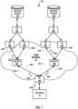
- FIG. 1 is a block diagram illustrating an example system including two multicast source devices configured to transmit anycast data to a multicast receiver according to the techniques of this disclosure.
- core network 10 includes multiple provider edge (PE) routers 20A-20E and other network devices including provider routers (PR) 22A-22B.
- System 90 may include private networks or public networks, such as the Internet and core network 10.
- system 90 include an enterprise network, a campus network, a service provider network, a home network, a local area network (LAN), a virtual local area network (VLAN), virtual private network (VPN), or another autonomous system.
- system 90 may include multiple autonomous systems (ASes).
- ASes autonomous systems
- a remotely located anycast source device 12A and anycast source device 12B may share anycast data via ingress PE router 20A - ingress PE router 20D, routers 22A and 22B and egress PE router 20E with receiver 18.
- core network 10 may be a multiprotocol label switching (MPLS) network.
- MPLS multiprotocol label switching
- Ingress PE router 20A is connected to anycast source device 12A via customer edge (CE) router 16A which may be located outside of system 90.
- Ingress PE router 20B is also connected to anycast source device 12A via CE router 16A. In this manner, anycast source device 12A and CE router 16A may be considered multi-homed.
- ingress PE router 20C is connected to anycast source device 12B via CE router 16B which may be located outside of system 90.
- Ingress PE router 20D is also connected to anycast source device 12B via CE router 16B. In this manner, anycast source device 12B and CE router 16B may be considered multi-homed.
- anycast source device 12A and anycast source device 12B are geographically separated to provide better redundancy.
- anycast source device 12A and anycast source device 12B may have a same IP address and may provide the same unicast data or content.
- Ingress PE routers 20A and 20B are linked to router 22A and ingress PE routers 20C and 20D are linked to router 22B. Both router 22A and router 22B are linked to egress PE router 20E which is linked (directly or indirectly) to receiver 18.
- Receiver 18 may be a multicast receiver configured to receive anycast traffic, such as IPTV traffic, and provide such traffic to a user for consumption. In some examples, receiver 18 may be external to system 90.
- ingress PE router 20A- ingress PE router 20D, egress PE router 20E, router 22A and router 22B may be devices that use multicast routing protocols, such as Protocol Independent Multicast (PIM) or Border Gateway Protocol (BGP), to route anycast traffic from anycast source device 12A and anycast source device 12B to receiver 18.
- system 90 may include one or more multicast virtual private networks (MVPNs) to enable anycast traffic to travel between anycast source device 12A and receiver 18 and between anycast source device 12B and receiver 18.
- the MVPN(s) may be established between ingress PE routers 20A-20D and egress PE router 20E of system 90.
- the PIM protocol may operate in several different modes, including Dense Mode (DM), Sparse Mode (SM) in Source-Specific Multicast (SSM) mode or Any Source Multicast (ASM) mode, and Bidirectional (BIDIR) mode.
- DM Dense Mode
- SM Sparse Mode
- SSM Source-Specific Multicast
- ASM Any Source Multicast
- BIDIR Bidirectional
- any or each of anycast source device 12A, anycast source device 12B, and receiver 18 may be included in a remote site (not shown) that may be a local area network (LAN) or a wide area network (WAN) including a plurality of subscriber devices, such as desktop computers, laptops, workstations, PDAs, wireless devices, network-ready appliances, file servers, print servers or other devices.
- the remote sites may be configured to support anycast traffic, such as Internet Protocol Television (IPTV), desktop conferences, corporate broadcasts, music and video web casts, and other forms of multimedia content.
- IPTV Internet Protocol Television
- system 90 may include unicast upstream multicast hop (UMH) and Selective Provider Tunnels (also referred to herein as “selective tunnels”).
- Inclusive Provider Tunnels also referred to herein as “inclusive tunnels” may be configured on the PE routers, such that any multicast (e.g., anycast) packet that is sent by an ingress PE router into a network will be received by all the PE routers connected to the network for that MVPN irrespective of whether the PE routers have interested listeners (e.g., receivers).
- an ingress PE router injects multicast (e.g., anycast) traffic in the MVPN by forwarding the traffic on all tunnels regardless of whether a receiver has expressly issued a multicast join request for the multicast source and group.
- multicast e.g., anycast
- Selective Provider Tunnel mode may be configured on the PE routers such that traffic sent by a particular PE router is delivered to subset of PE routers in a given MVPN instance that have signaled interested receivers, rather than to all PE routers in the MVPN instance. This signaling of interest may be through multicast join messages, such as multicast join message 30A and 30C.
- C-Join Customer-Join
- C-Prune Customer-Prune
- the message identifies a particular multicast flow as belonging either to a source-specific tree (S,G) or to a shared tree (*,G).
- C-root (Customer-Root)
- RP Rendezvous Point
- UDH Upstream Multicast Hop
- the UMH is either the PE router at which (S,G) or (*,G) data packets enter the VPN backbone or the Autonomous System Border Router (ASBR) at which those data packets enter the local AS when traveling through the VPN backbone.
- ASBR Autonomous System Border Router
- Segment routing which may also be referred to as source packet routing or source packet routing in networking (SPRING), is a control-plane architecture that enables an ingress router to steer a packet through a specific set of nodes and links in a network without relying on intermediate nodes in the network to determine the path it should take.
- ingress PE router 20A and egress PE router 20E may use segment routing techniques, e.g., a SPRING paradigm, to advertise segments between nodes using an IGP or BGP and build single or multi-hop tunnels within system 90. Segment routing may engage IGPs or BGP for advertising multiple types of segments.
- a first example type of segment is an "adjacency segment” that represents a strict-forwarded, typically single-hop tunnel that carries packets over a specific link between a router and a specific node, irrespective of the link cost.
- a second example type of segment is a "prefix segment” that represents a typically multi-hop tunnel using least cost path links between a router and to a specific address prefix.
- a third example type of segment is a "binding segment” that represents a specific intra-domain tunnel between a router and a specific node or a specific address prefix.
- Ingress PE router 20A is able to steer a packet through an ordered list of instructions or segments by prepending one or more segment identifiers (SIDs) to the packet.
- SIDs segment identifiers
- ingress router 20A can steer a packet through a desired set of nodes and links by prepending the packet with an appropriate combination (stack) of SIDs.
- Segment routing allows routers to enforce a flow through any topological path and service chain while maintaining per-flow state only at the ingress node to each domain.
- Segment routing can be directly applied to the MPLS architecture with no change in the forwarding plane.
- a network administrator or centralized controller need only allocate SIDs to particular routers and the segment routing control plane architecture automatically builds the required MPLS forwarding constructs from a router to any other router.
- a SID is encoded as an MPLS label, and an ordered list of SIDs is encoded as a stack of labels. The SID of the segment to be processed is on the top of the stack and, upon completion of a segment, the related label is popped from the stack as the packet is forwarded through the network.
- Segment routing is further described in Filsfils, et al., "Segment Routing Architecture,” IETF RFC 8402, July 2018 , while Segment Routing use cases are described in Filsfils, et al., “Segment Routing Use Cases,” IETF Internet-Draft draft-filsfils-spring-segment-routing-use-cases-01, October 21, 2014 .
- MVPN auto-discovery may be provided by a unicast routing protocol, such as BGP, used to discover and maintain MVPN memberships of PE routers within a network, such as system 90.
- BGP MVPN (sometimes referred to as "Next Generation (NG) MVPN”) introduces a BGP control plane in the provider network for handling multicast traffic.
- PE routers 20A-20E may use BGP control plane messages ("routes") for coordinating delivery of the multicast traffic.
- BGP MVPN introduces the concept of Provider Multicast Service Interfaces (PMSI) to bring separation between the "service” and "transport” mechanisms.
- PMSI Provider Multicast Service Interfaces
- a PMSI is a conceptual "overlay" on the provider network (P-network) that refers to a "service.” This "overlay" can take packets from one PE router belonging to a particular MVPN and deliver them to other or all the PE routers belonging to that same MVPN.
- BGP MVPN is responsible for three major functions: 1) Auto-discovery; 2) P-Tunnel Signaling; and 3) customer multicast (C-MCAST) Route Signaling.
- Auto-discovery is the process of finding all of the PE routers participating in a given MVPN instance.
- P-Tunnel signaling provides a way for PE routers to tell other PE routers what method they are going to use for transporting C-Multicast traffic (i.e., for establishing the PMSI tunnels).
- Options for establishing PMSI tunnels include point-to-multipoint (P2MP) RSVP-TE, P2MP mLDP, multi-point-to-multipoint (MP2MP) mLDP, multicast Generic Routing Encapsulation (mGRE) or Ingress replication.
- C-MCAST Route Signaling is a way of exchanging C-Multicast control plane state, such as C-Join, C-Prunes and C-Register messages between relevant PE routers.
- BGP MVPN uses selective provider tunnels, or selective provider multicast service interface (S-PMSI), and inclusive provider tunnels, or inclusive provider multicast service interface (I-PMSI).
- S-PMSI selective provider tunnels
- I-PMSI inclusive provider multicast service interface
- S-PMSI traffic sent by a particular PE router is delivered to subset of PE routers in a given MVPN instance, rather than to all PE routers in the MVPN instance.
- Creating a selective provider tunnel enables an ingress PE router to move high-rate traffic off the inclusive tunnel and deliver the multicast traffic only to receivers that request it. This can improve bandwidth utilization.
- PE routers participating in BGP MVPNs that use the BGP control plane use seven types of BGP MVPN routes (messages), five of which are used for auto-discovery and two for C-multicast protocol information exchange between PE routers.
- BGP MVPN routes messages
- PE routers 20 advertise their MVPN membership to other PE routers 20 using BGP
- PE routers 20 exchange BGP routing protocol messages to advertise various types of routes for controlling multicast distribution within the network.
- an MVPN Type-1 route is an intra-AS inclusive provider multicast service interface (I-PMSI) auto discovery (AD) route that is originated by all PE routers participating in an MVPN. That is, the MVPN Type-1 route is a type of auto discovery route.
- the MVPN Type-1 route includes a route type indicator, an originating router route distinguisher (RD), and an originating router loopback address.
- an MVPN Type-1 route may also include an extended community attribute, such as a site of origin (SOO) extended community attribute, which may include a customer site identifier that uniquely identifies a customer network device, such as CE router 16A or CE router 16B, according to the techniques of this disclosure.
- SOO site of origin
- An MVPN Type-2 route is an inter-AS I-PMSI AD Route that is originated by all ASBR PE routers.
- the MVPN Type-2 route includes a route type indicator, an originating router RD, and an AS number of the originating ASBR.
- An MVPN Type-3 route is a selective provider multicast service interface (S-PMSI) AD Route that is originated by the sender PE router (the sender PE router that initiates the S-PMSI).
- the MVPN Type-3 route includes a route type indicator, an originating router RD, Customer multicast Source address (C-S) Mask (32 for IPv4; 128 for IPv6), C-S Using S-PMSI, Customer multicast Group address (C-G) Mask (32 for IPv4; 128 for IPv6), C-G Using S-PMSI, and originating Router Loopback Address.
- C-S Customer multicast Source address
- C-G Customer multicast Group address
- An MVPN Type-4 route is a leaf AD Route that is originated by receiver PE routers in response to receiving S-PMSI AD routes with the "leaf information required" flag set from the sender PE router.
- the MVPN Type-4 route includes a route type indicator, an S-PMSI AD route, and an originating router loopback address.
- An MVPN Type-5 route is a source active AD Route that is originated by the PE router that discovers an active VPN multicast source.
- the MVPN Type-5 route is another type of auto discovery route.
- the MVPN Type-5 route includes a route type indicator, an originating router RD, C-S Mask (32 for IPv4; 128 for IPv6), Customer multicast Source address, C-G Mask (32 for IPv4; 128 for IPv6), Customer multicast Group address.
- an MVPN Type-5 route may also include an extended community attribute, such as an SOO extended community attribute, which may include a customer site identifier that uniquely identifies a customer network device, such as CE router 16A or CE router 16B, according to the techniques of this disclosure.
- An MVPN Type-6 route is a shared tree join route that is originated by the receiver PE router (the PE router that receives a (C-*, C-G) join message from a VPN interface).
- the MVPN type 6 route includes a route type indicator, RD of Upstream PE router (towards Customer Rendezvous Point (C-RP)), AS Number of Upstream PE router (towards C-RP), C-RP Mask (32 for IPv4; 128 for IPv6), Customer Rendezvous Point Address, C-G Mask (32 for IPv4; 128 for IPv6), and Customer multicast Group address.
- An MVPN Type-7 route is a source tree join route that is originated by the receiver PE router (the PE router that receives a local (C-S, C-G) join message or the PE router that already has a Type-6 route and receives a Type-5 route).
- the MVPN Type-7 route includes a route type indicator, RD of Upstream PE router (towards C-S), AS Number of Upstream PE router (towards C-S), C-S Mask (32 for IPv4; 128 for IPv6), Customer multicast Source Address, C-G Mask (32 for IPv4; 128 for IPv6), and Customer multicast Group address.
- ingress PE router 20A may have stored in memory a customer site identifier associated with CE router 16A.
- Ingress PE router 20A may advertise auto discovery routes (routes 32A), such as Type-1 routes and/or Type-5 routes, with an attached extended community attribute of SOO.
- ingress PE router 20A may advertise Type-1 routes with PMSI tunnel type as "IR" and extended community attribute SOO specifying a customer site identifier that uniquely identifies CE router 16A associated with anycast source device 12A (such as the router ID of CE router 16A).
- ingress PE router 20B may advertise Type-1 routes and/or Type-5 routes (routes 32B) with an attached extended community attribute of SOO specifying a customer site identifier that uniquely identifies CE router 16A associated with anycast source device 12A. Routes 32A and 32B may be forwarded by router 22A to egress PE router 20E.
- Ingress PE router 20C may advertise Type-1 routes and/or Type-5 routes (routes 32C) with an attached extended community attribute of SOO. For example, ingress PE router 20C may advertise routes 32C with a community attribute SOO specifying a customer site identifier that uniquely identifies CE router 16B associated with anycast source device 12B. Similarly, ingress PE router 20D may advertise Type-1 routes and/or Type-5 routes (routes 32D) with an attached extended community attribute of SOO specifying a customer site identifier that uniquely identifies CE router 16B associated with anycast source device 12B. Routes 32C and 32D may be forwarded by router 22B to egress PE router 20E.
- the customer site identifier may include a customer edge site ID, a customer router ID, an AS number and site ID, or other identifier.
- Example customer site identifiers may include any of the following: soo: ⁇ Router ID>: ⁇ 0>, soo: ⁇ AS Number>: ⁇ Site ID>, soo: 10.10.10.10.0, or soo: 100:1, or the like.
- the customer site identifier for CE router 16A may be different than the customer site identifier for CE router 16B.
- Egress PE router 20E may determine which paths are associated with anycast source device 12A, based on the customer site identifier for CE router 16A in the extended community attribute SOO received in routes 32A and 32B. Additionally, egress PE router 20E may determine which paths are associated with anycast source 12B, based on the customer site identifier for CE router 16A in the extended community attribute SOO received in routes 32C and 32D.
- next generation multicast virtual private network (NG-MVPN) upstream multicast hop (UMH) selection techniques include: 1) highest IP address; 2) unicast route (e.g., BGP best unicast route); 3) hash-based selection; 4) source active (SA) based UMH; and 5) static UMH which are described further below.
- NG-MVPN next generation multicast virtual private network
- UMH upstream multicast hop
- egress PE router 20E would select a primary UMH and a backup UMH for anycast flows to send multicast join messages in order to provide redundancy of the flows. Anycast flows from the primary UMH and backup UMH may then be sent to egress PE router 20E. In some examples, egress PE router 20E may forward the primary anycast flows to receiver 18 and discard the backup anycast flows under normal operation. If the primary stream is interrupted for some reason or the rate of transmission drops below a predetermined threshold, egress PE router 20E may sense the interruption or rate drop and begin forwarding the backup flows rather than the primary flows. In this manner, any outage of content at receiver 18 may be relatively brief.
- receiver 18 may send a multicast join message.
- a source device such as anycast source device 12A or anycast source device 12B.
- egress PE router 20E would select the highest IP address as that is the default according to the Internet Engineering Task Force (IETF) Request For Comments (RFC) 6513 standard.
- IETF Internet Engineering Task Force
- RRC Request For Comments
- egress PE router 20E may use another of the five selection techniques mentioned above. For example, egress PE router 20E may use unicast route, which may select a feed with the best path (e.g., the best route according to a BGP best path selection algorithm).
- egress PE router 20E may select a path using a hash-based load balancing scheme that may load balance multicast join messages and thereby balance received multicast flows. Such a scheme aims to select a portion of content, such as half from one feed and another portion of content, such as the other half from another feed to avoid overloading certain network devices.
- egress PE router 20E may receive Type-5 routes from multiple or all upstream feeds and select the flows based on policies which may be configured on egress PE router 20E.
- a network operator may statically provision the flows reaching egress PE router 20E.
- anycast sites may have the same IP address and push the same multicast content via flows.
- anycast sites are geographically dispersed.
- anycast source device 12A may be located in a separate physical location from anycast source device 12B, but anycast source device 12A and anycast source device 12B may both have the same IP address and push the same content, for example, the same 100 television channels.
- Anycast source device 12A and anycast source device 12B may be geographically separated for redundancy purposes.
- anycast source device 12A For example, if there is an incident, such as a power outage or fire, at the location of anycast source device 12A that causes anycast source device 12A to stop pushing traffic or go off-line, there may be a lower likelihood that anycast source device 12B would be similarly affected if anycast source device 12B is geographically separated from anycast source device 12A.
- anycast sites it may be desirable to load balance between anycast sites.
- network operators may require load balancing among anycast source device 12A and anycast source device 12B.
- current MVPN UMH techniques may not be capable of achieving load balancing between anycast sites.
- a network operator may desire that egress PE router 20E pull traffic for 50 television channels from anycast source device 12A and the other 50 television channels from anycast source device 12B to avoid overloading or reduce the likelihood of overloading any of the network devices, such as ingress PE routers 20A-20D or P 23A-23B.
- a customer may require multicast stream protection (e.g., redundancy) at egress PE router 20E.
- multicast stream protection e.g., redundancy
- egress PE router 20E selects a primary UMH path as being through ingress PE router 20A using any of existing UMH selection techniques and selects the backup UMH as ingress PE router 20B, when anycast source device 12A or CE router 16A fails (e.g., ceases to transmit traffic or otherwise does not meet transmission requirements), egress PE router 20E may experience the complete loss of anycast traffic until a control plane of egress PE router 20E converges to anycast source device 12B. This converging may take several seconds to several minutes.
- egress PE router 20E may have one of anycast source device 12A or 12B as the primary UMH and the other of anycast source device 12A or 12B as the backup UMH.
- both load balancing and redundancy may be achieved by selecting certain flows (e.g., television channels 1-50) from a first UMH as primary and other flows (e.g., television channels 51-100) from the first UMH as backup and the other flows (e.g., television channels 51-100) from a second UMH as primary and the certain flows (e.g., television channels 1-50) from the second UMH as backup.
- redundancy if one of anycast source device 12A or 12B fails, egress PE router 20E (and thus receiver 18) may avoid lengthy content outages as egress PE 20E may forward content sent by the backup UMH.
- CE router 16A (and, therefore, anycast source device 12A) is multihomed to ingress PE router 20A and ingress PE router 20B.
- egress PE router 20E may, in effect, perform a hash-based selection to determine one of anycast source device 12A and anycast source device 12B to which to send multicast join messages. This may result in better load balancing and/or redundancy in system 90.
- an egress router in an MVPN has visibility to the ingress PE routers through their advertisements, but not to the CE routers or to the anycast source devices. Therefore, absent the techniques of this disclosure, an egress PE router may not be able to determine which anycast source device is connected to which ingress PE router.
- egress PE router 20E would end up receiving all the anycast traffic from anycast source device 12A.
- anycast source device 12A or CE router 16A goes down, egress PE router 20E may take several seconds or several minutes to switch the primary UMH and/or the secondary UMH over to anycast source device 12B before egress PE router 20E (and receiver 18) may start receiving content again.
- This means a user of receiver 18 may be without content for a period of time that may not be acceptable to that user.
- messages from each ingress PE router 20A-20D may include an extended community attribute specifying a customer site identifier that uniquely identifies a customer network device via which the anycast IP address is reachable.
- an MVPN module executing on ingress network device 20A may query a PE-CE protocol (e.g., BGP/IGP) executing on the ingress network device 20A to obtain a customer site ID, e.g., a CE router ID, such as an identifier CE router 16A in the example of FIG. 1 .
- a PE-CE protocol e.g., BGP/IGP
- the MVPN module may then tag MVPN Type-1 (Intra-AS AD) routes and/or Type-5 (SA AD) routes with the customer site identifier (e.g., CE router ID).
- the MVPN may use a site of origin (SOO) extended community attribute field to carry this value. For example, soo: ⁇ CE Router ID>: ⁇ 0>.
- an administrator may provision the SOO on each MVPN PE router.
- the MVPN module on each ingress PE router may tag MVPN Type-1 (Intra-AS AD) routes and/or Type-5 (SA AD) routes with the SOO extended community. For example, an SOO of format soo: ⁇ AS Number>: ⁇ Site ID> may be tagged.
- Type-1/Type-5 routes associated with anycast source device 12A may carry soo:10.10.10.10:0 and Type-1/Type-5 routes associated with anycast source device 12B (e.g., routes 32C from ingress PE router 20C and routes 32D from ingress PE router 20D) may carry soo:20.20.20.20:0.
- Type-1/Type-5 routes associated with anycast source device 12A may carry soo:100:1
- Type-1/Type-5 routes associated with anycast source device 12B e.g., routes 32C from ingress PE router 20C and routes 32D from ingress PE router 20D
- routes 32C from ingress PE router 20C and routes 32D from ingress PE router 20D may carry soo:100:2.
- egress PE router 20E may be enabled to determine the anycast source device providing content to each of the PEs (e.g., ingress PE routers 20A-20D). In this way, the PE routers 20 use the CE router ID as a proxy for a source identifier. If two ingress PE routers advertise the same customer site ID, the egress PE router can determine they are receiving the anycast content from the same source. If two ingress PE routers advertise different customer site IDs, the egress PE router can determine they are receiving anycast traffic from different sources.
- Egress PE router 20E may store, in memory, the customer site identifier associated with each ingress PE routers 20A-20D along with an indication of the associations.
- egress PE router 20E may employ UMH procedures which may be extended to hash multicast join messages based on the customer site identifier that uniquely identifies a customer network device (e.g., CE router ID) via which the anycast address is reachable.
- ingress PE router 20A may perform a BGP or IGP obtain of a CE router 16A router ID which may be associated with anycast source device 12A.
- Now ingress PE router 20A may store in memory the router ID of CE router 16A which is associated with anycast source device 12A.
- Ingress PE router 20A may then advertise the router ID of CE router 16A via an SOO extended community attribute via ingress PE router 20A's Type-1 and/or Type-5 routes (routes 32A).
- each connected MVPN ingress PE router may determine a CE router ID of a connected CE router, store the CE router ID and provide the CE router ID through Type-1 and/or Type-5 routes to all connected MVPN PE routers, such as egress PE router 20E.
- egress PE router 20E may be able to determine which ingress PE routers in the MVPN are on a path to anycast source device 12A and which are on a path to anycast source device 12B.
- a network operator may statically provision the CE router ID from anycast source device 12A in ingress PE router 20A.
- now egress PE router 20E may hash 50 multicast join messages [ (S1,G1)....(S1,G50) ] to anycast source device 12A and another 50 multicast join messages [ (S1,G51)....(S1,G100) ] to anycast source device 12B.
- each of anycast source device 12A and anycast source device 12B has two connected UMH ingress PE routers.
- the multicast join messages are further hashed between these two UMH ingress PE routers.
- an egress PE router such as egress PE router 20E may employ an enhanced hash algorithm.
- the upstream anycast source devices in a source candidate list may be numbered from lowest to highest customer site identifier (e.g., CE router ID), starting from 0.
- egress PE router 20E may number CE router 16A as 0 and may number CE router 16B as 1. If there were a third customer site, egress PE router 20E may number the third customer site identifier as 2, and so on.
- Egress PE router 20E may perform a bytewise-exclusive-or(XOR)-hash as defined in RFC 6513 of all bytes in C-root address and C-G address.
- Egress PE router 20E may take the results of the bytewise-XOR-hash and perform a modulo n operation, where n is the number of unique upstream customer site identifiers in the source candidate list (e.g., 2 in the example of FIG. 1 ). For example, egress PE router 20E may take the result of the hash function modulo n to determine an index number. In some examples, if the result of the modulo n operation is N (e.g., the index number), the selected upstream customer site is the customer site that appears in position N of above list. For example, egress PE router 20E may select one of the one or more of the plurality of ingress network devices to which to send a multicast join message based on the index number.
- N e.g., the index number
- egress PE router 20E may further hash the multicast join messages to UMH ingress PE routers in the selected upstream source device path as follows.
- Egress PE router 20E may number the upstream ingress PE routers in a source candidate list from lowest to highest IP address, starting from 0.
- Egress PE router 20E may perform a bytewise-XOR-hash of all bytes in C-root address & C-G address.
- Egress PE router 20E may take the results of the bytewise-XOR-hash and perform a modulo m operation, where m is the number of upstream ingress PE routers in the source candidate list.
- egress PE router 20E may take the result of the hash function modulo m to determine a second index number (e.g., 2 in the example of FIG. 1 ). If the result of the modulo m operation is M (e.g., a second index number), the selected upstream ingress PE router is the one that appears in position M of the above list. For example, egress PE router 20E may select one of the one or more of the plurality of ingress network devices to which to send a multicast join message based on the second index number.
- M e.g., a second index number
- egress PE router 20E may select a primary path through an ingress PE router that leads to one anycast source device, such as anycast source device 12A, and a backup path through an ingress PE router that leads to another source device, such as anycast source device 12B.
- egress PE router 20E may use the above-mentioned hashing algorithm to determine where to send multicast join messages.
- egress PE router 20E may create list of CE routers associated with anycast source devices, such as CE router 16A and CE router 16B, and number CE router 16A as 0, and CE router 16B a 1, and so on.
- the above-referenced hashing algorithm may be used to determine where to send the multicast join messages. In some examples, the process may be repeated for every multicast join message received by egress PE router 20E.
- backup UMH procedures can be extended as follows.
- egress PE router 20E may send two multicast join message per flow - one for a primary flow and one for a backup flow.
- Egress PE router 20E may obtain from memory the customer site identifier (e.g., the router ID of CE router 16A) associated with the primary UMH (e.g., ingress PE router 20A) or extract the customer site identifier from routes 32A.
- Egress PE router 20E may scan a source candidate list to identify all UMHs having the same customer site identifier as that of primary UMH.
- Egress PE router 20E may trim the source candidate list to remove all UMHs that have the same customer site identifier (which may indicate they are coupled to same customer site as that of primary UMH). Egress PE router 20E may then execute procedures to select a backup UMH from trimmed source candidate list. For example, egress PE router 20E may uses existing procedures to select the backup ingress PE router from the trimmed source candidate list, such as highest IP address, SA based UMH, or second-best unicast route, among others.
- This technique may ensure that a primary flow and a backup flow are from different anycast source devices (e.g., one from anycast source device 12A and one from anycast source device 12B) and therefore bring redundancy between the anycast source devices to address the possibility of an anycast source device failure or a CE router failure within a particular customer site.
- anycast source devices e.g., one from anycast source device 12A and one from anycast source device 12B
- the techniques of this disclosure are applicable to Intra-AS (autonomous systems) and Inter-AS multi-homed BGP-MVPN deployments. These techniques may utilize multicast traffic hashing (e.g., load balancing) based on customer site identifiers in anycast deployments. These techniques may provide maximally redundant multicast trees that provide protection against multicast source failures in anycast deployments. In accordance with the techniques of this disclosure, no changes in forwarding constructs are needed in a BGP-MVPN PE router as the problems this disclosure addresses are handled in a control plane. These techniques may be used for IPv4 and/or IPv6 multicast and for all BGP-MVPN UMH devices. In some examples, the techniques of this disclosure are applicable to other multicast deployments other than MVPN.
- multicast traffic hashing e.g., load balancing
- the techniques of this disclosure may be used for any multicast deployment.
- the techniques of this disclosure may be used with an Ethernet VPN.
- the techniques of this disclosure may be used with broadcast, unknown unicast and multicast traffic.
- the techniques of this disclosure may be used with a Rosen-MVPN.
- the techniques of this disclosure may be used with a PIM network with a field in a PIM message carrying the customer site identifier.
- an IGP or BGP unicast route may carry the customer site identifier.
- FIG. 2 is a block diagram illustrating an example network device 50 configured to operate in accordance with techniques of this disclosure.
- network device 50 may operate as an ingress network device to a network, such as an MPLS network.
- network device 50 may operate as an egress network device.
- network device 50 is configured to determine a customer site identifier, such as a CE router ID, associated with a source device, such as anycast source device 12A and advertise the customer site identifier via Type-1 and/or Type-5 routes as a BGP extended community attribute, such as SOO.
- a customer site identifier such as a CE router ID
- source device such as anycast source device 12A
- BGP extended community attribute such as SOO
- network device 50 may operate substantially similarly to ingress PE routers 20A-20D of FIG. 1 .
- network device 50 is configured to receive messages from each of a plurality of ingress network devices for the network, wherein each of the messages specifies a multicast source as an anycast address that belongs to two or more different sources, a multicast group, and a customer site identifier that uniquely identifies a customer network device via which the anycast address is reachable.
- Network device 50 is also configured to select, based on the customer site identifiers specified by the messages, one of the plurality of ingress network devices to which to send a multicast join message of a plurality of multicast join messages for the multicast source and multicast group.
- Network device 50 is further configured to send the multicast join message to the selected one of the plurality of ingress network devices.
- network device 50 may operate substantially similarly to egress PE router 20E of FIG. 1 .
- network device 50 includes interface cards 60A-60N ("IFCs 60") that receive control and data packets via incoming links and send control and data packets via outbound links. IFCs 60 are typically coupled to the incoming links and the outbound links via a number of interface ports. Network device 50 also includes a control unit 54 that determines routes of received packets and forwards the packets accordingly via IFCs 60.
- IFCs 60 interface cards 60A-60N
- Control unit 54 includes a routing engine 56 and a forwarding engine 58.
- Routing engine 56 operates as the control plane for router 50 and includes an operating system (not shown) that may provide a multi-tasking operating environment for execution of a number of concurrent processes.
- routing engine 56 provides an operating environment for various protocols 66 that perform routing functions for network device 50.
- routing engine 56 includes a BGP 70 as a unicast routing protocol used to exchange routing information, with other network devices in a network in order to discover the network topology and update routing information 62, and sending routes for MVPN auto-discovery, provider tunnel signaling, and customer multicast route signaling.
- BGP 70 may also be used to exchange extended community attributes, such as SOO between network device indicating a customer site identifier that uniquely identifies a customer network device via which the anycast address is reachable.
- protocols 66 of routing engine 56 includes RSVP 46 used to exchange bandwidth reservation information and labels to build RSVP tunnels, IGP 48 used to exchange link state information along with labels and/or SIDs to build SR tunnels and PIM 68 as a multicast routing protocol used to build multicast distribution trees with the other network devices in the network using routing information 62 and multicast state information 64.
- Protocols 66 of routing engine 56 also includes internet group management protocol (IGMP) 72 as a communications protocol used to establish multicast group memberships with IGMP hosts, e.g., receivers and sources, within customer sites external to the network.
- IGMP internet group management protocol
- routing engine 56 may receive IGMP report messages identifying a multicast group and, in some cases, a source of the multicast group in which an IGMP host is interested.
- Routing engine 56 may, in some examples, use PIM 68 to generate the multicast control messages (e.g., PIM join messages and/or PIM prune messages) used to build the multicast distribution trees in the network.
- Routing information 62 may describe the topology of the network in which network device 50 resides, and may also describe various routes within the network and the appropriate next hops for each route, i.e., the neighboring network devices along each of the routes.
- Routing information 62 may include a list of incoming interfaces (IIFs) and a list of outgoing interfaces (OIFs) that indicate which of IFCs 60 are connected to the neighboring network devices in each route.
- a given route may comprise a multicast route for multicast traffic of a given multicast group.
- the list of IIFs included in routing information 62 may include a list of upstream interfaces for all upstream neighbor network devices that have state for the given multicast group
- the list of OIFs included in routing information 62 may include a list of downstream interfaces for all downstream neighbor network devices that have state for the given multicast group.
- Multicast state information 64 may describe a current status of interfaces for the neighboring network devices in the multicast distribution trees established using PIM 68.
- multicast state information 64 may include multicast state (e.g., PIM join state and PIM prune state) for each different multicast group within a range for a given multicast distribution tree. More specifically, for each multicast group, multicast state information 64 may include upstream and downstream interfaces toward neighboring network devices that belong to the respective multicast group.
- MVPN module 74 may be configured to establish and maintain MVPN distribution trees or tunnels within the network using one or both of PIM 68 and BGP 70. For example, MVPN module 74 may signal TE module 76 to initiate establishment of TE tunnels, such as SR-TE tunnels, RSVP-TE tunnels, or other tunnels. MVPN module 74 may contain MVPN route table 75 which may include a list indicative of which customer site identifiers are associated with which links or with which ingress PE routers.
- Forwarding engine 58 may receive BGP messages and may forward received messages to MVPN module 74 for processing.
- MVPN module 74 may map MVPN membership information of other network devices within the network and generate multicast state for a given MVPN based on the MVPN membership information.
- MVPN module 74 may store multicast state for one or more MVPNs in multicast state information 64.
- Routing engine 56 analyzes routing information 62 and multicast state information 64 to generate forwarding information 78 installed in forwarding engine 58.
- Forwarding engine 58 provides data plane functionality for network device 50.
- forwarding engine 58 may comprise a central processing unit (CPU), memory and one or more programmable packet-forwarding application-specific integrated circuits (ASICs).
- Forwarding information 78 associates network destinations with specific next hops and corresponding ports of IFCs 60.
- network device 50 is configured such that when network device 50 receives a Type-1 route (and/or a Type-5 route) having an extended community attribute SOO, network device 50 determines the customer site identifier within the extended community attribute SOO attached to the Type-1 (and/or Type-5) route. Network device may then store the SID, ingress PE router ID or other information associated with the received route and the customer site identifier in MVPN route table 75, thereby storing an association between the ingress PE router and the customer site identifier.
- network device 50 When network device 50 queries a CE router to obtain a customer site identifier, such as in some examples where network device 50 is an ingress network device, network device 50 may store the customer site identifier and, in some examples, other information associating the customer site identifier with the CE router, such as the link or port of network device 50 that is coupled to the CE router, an IP address associated with the CE router, or the like, in MVPN route table 75. While MVPN route table 75 is shown outside of routing information 62, in some examples, MVPN route table 75 may be part of routing information 62. Further details of MVPN module 74 are described with respect to FIG. 3 .
- control unit 54 may be implemented solely in software, or hardware, or may be implemented as a combination of software, hardware, or firmware.
- control unit 54 may include one or more processors which execute software instructions.
- the various software modules of control unit 54 may comprise executable instructions stored on a computer-readable medium, such as computer memory or hard disk.
- FIG. 3 is a block diagram of an example MVPN module of a network device according to the techniques of this disclosure.
- MVPN module 74 includes obtain site ID module 102, extended community attribute module 104, load balancing module 106, hashing module 108, primary/backup selection module 110, and MVPN route table 75.
- MVPN module 74 may contain fewer or more modules. For example, if network device 50 is not an MVPN ingress PE, MVPN module 74 may not include obtain site ID module 102.
- Obtain site ID module 102 may be used by network device 50 to obtain a customer site identifier that uniquely identifies a customer site or a customer network device.
- obtain site ID module 102 may obtain a CE router ID that may uniquely identify the CE router.
- obtain site ID module 102 may query PE-CE protocol (e.g., BGP 70 or IGP 48 of FIG. 2 ) to obtain a customer site identifier, for example, a CE router ID. In this manner, obtain site ID module may obtain the customer site identifier.
- PE-CE protocol e.g., BGP 70 or IGP 48 of FIG. 2
- Obtain site ID module 102 may store the obtained customer site identifier in MVPN route table 75. In some examples, obtain site ID module 102 may also store additional information associated with the customer site identifier, such as the link or port of network device 50 that is associated with the customer site identifier, an IP address associated with the customer site identifier, or the like. Alternatively, or in addition, obtain site ID module 102 may store the customer site identifier in another data structure accessible to extended community attribute module 104.
- Extended community attribute module 104 may use BGP 70 to advertise via the extended community attribute SOO the stored customer site identifier over Type-1 and/or Type-5 routes.
- extended community attribute module 104 may send auto discovery messages (e.g., Type-1 and/or Type-5 routes) that specify a multicast source as an anycast address.
- the anycast address may belong to two or more different sources, such as anycast source device 12A and anycast source device 12B of FIG. 1 .
- the messages may also specify a multicast group, such as a particular MVPN, and the customer site identifier. These messages may be forwarded by network devices to an egress network device, such as egress PE router 20E of FIG. 1 .
- An egress network device for a network may receive messages from each of a plurality of ingress network devices for the network (e.g., ingress PE routers 20A-20D of FIG. 1 ). Each of the messages may specify a multicast source as an anycast address that belongs to two or more different sources, a multicast group, and a customer site identifier that uniquely identifies a customer network device via which the anycast address is reachable.
- Extended community attribute module 104 of the egress network device may extract the customer site identifiers from the messages and store the customer site identifiers along with other information such as the SID, ingress PE router ID associated with a particular received message and the associated customer site identifier in MVPN route table 75, thereby storing an association between a particular ingress PE router and a unique customer site identifier.
- Load balancing module 106 may be used by network device 50, when network device 50 is an egress network device, to load balance flows between different anycast source devices and, in some examples, ingress network devices.
- load balancing module 106 may employ an enhanced hash algorithm on multicast join messages received from a multicast receiver to determine to which CE routers or which ingress network devices to send the multicast join messages.
- the join messages may be PIM join messages.
- load balancing module 106 may determine a source candidate list based on the customer set identifiers (e.g., a list of CE routers delivering anycast flows) specified by auto discovery routes received from ingress PE routers.
- Load balancing module 106 may number each candidate in the source candidate list from lowest to highest customer site identifier (e.g., CE router ID), starting from 0. Load balancing module 106 may interact with hashing module 108 to perform a bytewise-XOR-hash as defined in RFC 6513 of all bytes in C-root address and C-G address of a given multicast join message. Hashing module 108 may take the results of the bytewise-XOR-hash and perform a modulo n operation, where n is the number of unique upstream customer site identifiers in the source candidate list (e.g., 2 in the example of FIG. 1 ).
- hashing module 108 may take the result of the hash function modulo n to determine an index number. In some examples, if the result of the modulo n operation is N (e.g., the index number), the selected upstream customer site is the customer site associated with the customer site identifier that appears in position N of above list. For example, hashing module 108 may select one of the one or more of the plurality of ingress network devices to which to send the received multicast join message based on the index number. Hashing module 108 may notify load balancing module 106 of the selected upstream customer site for the given multicast join message.
- N e.g., the index number
- load balancing module 106 may further use hashing module 108 to select a particular ingress PE network device to which to send the multicast join message rather than just any ingress network device associated with the customer site identifier. For example, load balancing module 106 may determine a second source candidate list of each ingress network device associated with the selected customer site identifier (e.g., ingress PE router 20A and ingress PE router 20B of FIG. 1 associated with the customer site identifier for CE router 16A). Load balancing module 106 may number each ingress network device in the source candidate list from lowest to highest IP address, starting from 0.
- Load balancing module 106 may interact with hashing module 108 to perform a bytewise-XOR-hash as defined in RFC 6513 of all bytes in C-root address and C-G address of the given multicast join message.
- Hashing module 108 may take the results of the bytewise-XOR-hash and perform a modulo m operation, where m is the number of ingress network devices in the source candidate list (e.g., 2 in the example of FIG. 1 ).
- load balancing module 106 may take the result of the hash function modulo m to determine a second index number.
- the selected ingress network device is the ingress network device that appears in position M of above list.
- hashing module 108 may select one of the one or more of the plurality of ingress network devices to which to send a multicast join message based on the second index number.
- Hashing module 108 may notify load balancing module 106 of the selected ingress network device for the given multicast join message.
- Load balancing module 106 may direct the given multicast join message towards the selected ingress network device or CE router associated with the customer site identifier by interacting with other modules of network device 50. Load balancing module 106 may repeat this process for each received multicast join message.
- Primary/backup selection module 110 may be used by network device 50, when network device 50 is an egress network device, to determine a primary flow and a backup flow for a given multicast join message to provide redundancy for the flow in case there is an interruption of the flow or a degradation of the flow.
- primary/backup selection module 110 may employ an enhanced hash algorithm on multicast join messages received from a multicast receiver to determine to which CE routers or which ingress network devices to send a copy of the multicast join message. Once the CE routers or ingress network devices are selected, primary/backup selection module 110 may direct a copy of the multicast join message to both the CE router or ingress network device selected for the primary flow and the CE router or ingress network device selected for the backup flow.
- primary/backup selection module 110 may determine a source candidate list based on the customer set identifiers (e.g., a list of CE routers delivering anycast flows). Primary/backup selection module 110 may number each candidate in the source candidate list from lowest to highest customer site identifier (e.g., CE router ID), starting from 0. Primary/backup selection module 110 may interact with hashing module 108 to perform a bytewise-XOR-hash as defined in RFC 6513 of all bytes in C-root address and C-G address of a given multicast join message.
- customer set identifiers e.g., a list of CE routers delivering anycast flows.
- Primary/backup selection module 110 may number each candidate in the source candidate list from lowest to highest customer site identifier (e.g., CE router ID), starting from 0.
- Primary/backup selection module 110 may interact with hashing module 108 to perform a bytewise-XOR-hash as defined in RFC 6513 of all bytes in C-root address
- Hashing module 108 may take the results of the bytewise-XOR-hash and perform a modulo n operation, where n is the number of unique upstream customer site identifiers in the source candidate list (e.g., 2 in the example of FIG. 1 ). For example, hashing module 108 may take the result of the hash function modulo n to determine an index number. In some examples, if the result of the modulo n operation is N (the index number), the selected primary upstream customer site is the customer site associated with the customer site identifier that appears in position N of above list. Hashing module 108 may notify load balancing module 106 of the selected upstream primary customer site for the given multicast join message.
- primary/backup selection module 110 and hashing module 108 may select a primary ingress network device rather than a primary customer site for the given multicast join message in a similar manner to the selection of the ingress network device by load balancing module 106 and hashing module 108 discussed above.
- Primary/backup selection module 110 may store an indication of which customer site (e.g., CE router) or ingress network device is selected as primary for a given flow, for example, in MVPN route table 75.
- Primary/backup selection module 110 may then scan through the source candidate list and trim the source candidate list by removing any candidates having the same customer site identifier as that of the selected upstream primary customer site. Primary/backup selection module 110 may then use any existing procedures to select a backup flow from the remaining candidates in the source candidate list, such as highest IP address, SA based UMH, or 2nd best unicast route, among others. By removing the candidates from the source candidate list that have the same customer site identifier as that of the selected upstream primary customer site for a given flow, primary/backup selection module 110 may ensure that the backup customer site and the backup ingress network device are different than the primary customer site for that given flow.
- Primary/backup selection module 110 may store an indication of which customer site or ingress network device is selected as backup for the given flow, for example, in MVPN route table 75.
- primary/backup selection module 110 may determine which flow is primary and/or which flow is backup, for example, by looking up a stored indication(s) in MVPN route table 75, and forward the primary flow towards receiver 18 and discard the secondary flow.
- primary/backup selection module 110 may make the backup the primary and store an indication of the change, e.g., in MVPN route table 75.
- Primary/backup selection module 110 may then determine a backup for the flow according to any of the techniques described herein or may make the former primary flow, the backup flow.
- an MVPN module 74 may include load balancing module 106 but may not include primary/backup selection module 110, or vice versa.
- each of modules 106 and 110 can, if desired, operate independently of each other in a standalone manner, in a device that does not include the other one of the modules.
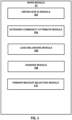
- FIG. 4 is a flowchart illustrating an example operation of a network device according to the techniques of this disclosure.
- Network device 50 may receive messages from each of a plurality of ingress network devices for the network, wherein each of the messages specifies a multicast source as an anycast address that belongs to two or more different sources, a multicast group, and a customer site identifier that uniquely identifies a customer network device via which the anycast address is reachable (200).
- network device 50 e.g., egress PE router 20E of FIG. 1
- the Type-1 and/or Type-5 routes may each specify an IP address associated with two or more different anycast source devices (e.g., anycast source devices 12A and 12B).
- the Type-1 and/or Type-5 routes may each also specify a multicast group, such as an MVPN.
- the Type-1 and/or Type-5 routes may each also specify a customer site identifier, such as a CE router ID.
- Network device 50 may select, based on the customer site identifiers specified by the messages, one of the plurality of ingress network devices to which to send a multicast join message of a plurality of multicast join messages for the multicast source and multicast group (202). For example, network device 50 may determine a source candidate list of customer site identifiers or ingress network devices. Network device 50 may number the candidates in the source candidate list starting with 0 based on the customer site identifiers or the IP addresses of the ingress network devices. Network device 50 may receive a multicast join message from receiver 18, such as multicast join message 30A.
- Network device 50 may apply a hash function comprising a bytewise exclusive-or operation on bytes in the Customer-Root address and the Customer-Group address of the multicast join message to obtain a result of the hash function.
- Network device 50 may take the results of the hash function modulo n to determine an index number, wherein n is equal to a total number of unique customer site identifiers received by the egress network device (e.g., the number of customer site identifiers in the source candidate list - 2 in the example of FIG. 1 ).
- Network device 50 may select the one of ingress PE routers 20A-20D to which to send a multicast join message based on the index number. For example, network device 50 may select the ingress network device whose associated customer site identifier numbering in the source candidate list matches the index number or may select one of the ingress PE routers 20A-20D whose numbering in the source candidate list matches the index number.
- Network device 50 may send the multicast join message to the selected one of the plurality of ingress network devices (204). For example, network device 50 may send multicast join message 30A to ingress PE router 20A.
- network device 50 may receive multicast traffic for the multicast source and multicast group from one or more of the plurality of ingress network devices in proportion to a plurality of multicast join messages sent to each ingress network device and forward the multicast traffic. For example, network device 50 may send multicast join messages 30A and 30C to ingress PE router 20A and ingress PE router 20C respectively and may receive half of the multicast traffic from ingress PE router 20A (e.g., television channels 1-50) and half of the multicast traffic from ingress PE router 20C (e.g., television channels 51-100).
- ingress PE router 20A e.g., television channels 1-50
- ingress PE router 20C e.g., television channels 51-100
- the one the plurality of ingress network devices is selected as a primary ingress network device
- network device 50 may select, based on a customer site identifier specified by a message associated with a different one of the plurality of ingress network devices, the different one of the plurality of ingress network devices as a backup ingress network device to which to send a multicast join message of a plurality of multicast join messages for the multicast source and multicast group.
- Network device may send the multicast join message to the selected backup ingress network device.
- a customer site identifier specified by a message associated with the primary ingress network device is different than the customer site identifier specified by the message associated with the backup ingress network device.
- network device 50 may determine a source candidate list based on the customer site identifiers. As part of selecting the backup ingress network device, network device 50 may trim the source candidate list based on a customer site identifier associated with the primary ingress network device. Network device 50 may select one of the one or more of the plurality of ingress network devices, based on the trimmed source candidate list, to which to send a multicast join message based on the index number.
- network device 50 may receive a first plurality of flows from the primary ingress network device (e.g., ingress PE router 20A) in response to the multicast join message (e.g., multicast join message 30A) sent to the primary ingress network device.
- Network device 50 may receive a second plurality of flows from the backup ingress network device (ingress PE router 20C) in response to the multicast join message (e.g., multicast join message 30C) sent to the backup ingress network device.
- Network device 50 may forward at least a portion of the first plurality of flows towards receiver 18.
- network device 50 may forward at least a portion of the second plurality of flows towards the multicast receiver.
- the at least a portion of the first plurality of flows contain first content (e.g., television channels 1-50), the at least a portion of the second plurality of flows contain second content (e.g., television channels 51-100), and the first content is different than the second content.
- first content e.g., television channels 1-50
- second content e.g., television channels 51-100
- the messages from each of the plurality of ingress network devices comprise auto discovery messages for the multicast source and the multicast group.
- network device 50 comprises an egress provider edge router of a network
- the plurality of ingress network devices comprise a plurality of ingress provider edge routers of the network.
- receiving the messages comprises receiving Border Gateway Protocol (BGP) Multicast Virtual Private Network (MVPN) auto discovery messages each comprising a BGP extended community attribute that specifies a customer site identifier.
- BGP Border Gateway Protocol
- MVPN Multicast Virtual Private Network
- the techniques described herein may be easily implementable, as new functionality has to be added only on the control plane, for example, in the MVPN module.
- the solution may be simple to operate and manage and may provide for a way of meeting customer requirements relating to load balancing, redundancy, or both load balancing and redundancy in anycast deployments.
- processors including one or more microprocessors, digital signal processors (DSPs), application specific integrated circuits (ASICs), field programmable gate arrays (FPGAs), or any other equivalent integrated or discrete logic circuitry, as well as any combinations of such components.
- DSPs digital signal processors
- ASICs application specific integrated circuits
- FPGAs field programmable gate arrays
- processors may generally refer to any of the foregoing logic circuitry, alone or in combination with other logic circuitry, or any other equivalent circuitry.
- a control unit comprising hardware may also perform one or more of the techniques of this disclosure.
- Such hardware, software, and firmware may be implemented within the same device or within separate devices to support the various operations and functions described in this disclosure.
- any of the described units, modules or components may be implemented together or separately as discrete but interoperable logic devices. Depiction of different features as modules or units is intended to highlight different functional aspects and does not necessarily imply that such modules or units must be realized by separate hardware or software components. Rather, functionality associated with one or more modules or units may be performed by separate hardware or software components, or integrated within common or separate hardware or software components.
- Computer-readable medium such as a computer-readable storage medium, containing instructions. Instructions embedded or encoded in a computer-readable medium may cause a programmable processor, or other processor, to perform the method, e.g., when the instructions are executed.
- Computer-readable media may include non-transitory computer-readable storage media and transient communication media. Transient communication media may occur between components of a single computer system and/or between multiple computer systems, and may include carrier waves, transmission signals and the like.
- Computer readable storage media which is tangible and non-transitory, may include random access memory (RAM), read only memory (ROM), programmable read only memory (PROM), erasable programmable read only memory (EPROM), electronically erasable programmable read only memory (EEPROM), flash memory, a hard disk, a CD-ROM, a floppy disk, a cassette, magnetic media, optical media, or other computer-readable storage media.
- RAM random access memory
- ROM read only memory
- PROM programmable read only memory
- EPROM erasable programmable read only memory
- EEPROM electronically erasable programmable read only memory
- flash memory a hard disk, a CD-ROM, a floppy disk, a cassette, magnetic media, optical media, or other computer-readable storage media.
- an egress network device that includes at least one computer processor and a memory.
- the memory includes instructions that cause the at least one computer processor to receive messages from each of a plurality of ingress network devices. Each message specifies a multicast source as an anycast address that belongs to two or more sources, a multicast group, and a customer site identifier that uniquely identifies a customer network device via which the anycast address is reachable.
- the instructions cause the at least one computer processor to select, based on the customer site identifiers, one of the plurality of ingress network devices to which to send a multicast join message of a plurality of multicast join messages for the multicast source and multicast group.
- the instructions cause the at least one computer processor to send the multicast join message to the selected one of the plurality of ingress network devices.
Landscapes
- Engineering & Computer Science (AREA)
- Computer Networks & Wireless Communication (AREA)
- Signal Processing (AREA)
- Data Exchanges In Wide-Area Networks (AREA)
Claims (15)
- Verfahren, umfassend:Empfangen, durch eine Ausgangs-Netzwerkvorrichtung (20E) für ein Netzwerk (10), von Nachrichten von jeder einer Mehrzahl von Eingangs-Netzwerkvorrichtungen (20A, 20B, 20C, 20D) für das Netzwerk, wobei jede der Nachrichten eine Multicast-Quelle als eine Anycast-Adresse, die zu zwei oder mehr verschiedenen Quellen (12A, 12B) gehört, eine Multicast-Gruppe und einen Kundenstandort-Identifikator vorgibt, der eine Kunden-Netzwerkvorrichtung (16A, 16B), über die die Anycast-Adresse erreichbar ist, eindeutig identifiziert;Auswählen, durch die Ausgangs-Netzwerkvorrichtung und basierend auf den durch die Nachrichten vorgegebenen Kundenstandort-Identifikatoren, einer der Mehrzahl von Eingangs-Netzwerkvorrichtungen, an die eine Multicast-Join-Nachricht aus einer Mehrzahl von Multicast-Join-Nachrichten (30A, 30C) für die Multicast-Quelle und Multicast-Gruppe zu senden ist; undSenden, durch die Ausgangs-Netzwerkvorrichtung, der Multicast-Join-Nachricht an die ausgewählte der Mehrzahl von Eingangs-Netzwerkvorrichtungen.
- Verfahren nach Anspruch 1, das ferner umfasst:im Anschluss an das Senden der Multicast-Join-Nachricht, Empfangen durch die Ausgangs-Netzwerkvorrichtung, von Multicast-Verkehr für die Multicast-Quelle und Multicast-Gruppe von einer oder mehreren der Mehrzahl von Eingangs-Netzwerkvorrichtungen im Verhältnis zu einer Mehrzahl von Multicast-Join-Nachrichten, die an jede Eingangs-Netzwerkvorrichtung gesendet werden; undWeiterleiten, durch die Ausgangs-Netzwerkvorrichtung, des Multicast-Verkehrs.
- Verfahren nach Anspruch 1 oder 2, wobei das Auswählen der einen der Mehrzahl von Eingangs-Netzwerkvorrichtungen umfasst:Anwenden einer Hash-Funktion, die einen byteweisen exklusiven Oder-Vorgang auf Bytes in einer Kunden-Stammadresse und einer Kunden- Gruppenadresse der Multicast-Join-Nachricht umfasst, um ein Ergebnis der Hash-Funktion zu erhalten;Nehmen des Ergebnisses der Hash-Funktion modulo n, um eine Indexzahl zu bestimmen, wobei n gleich einer Gesamtzahl von eindeutigen Kundenstandort-Identifikatoren ist, die durch die Ausgangs-Netzwerkvorrichtung empfangen werden; undAuswählen einer der einen oder mehreren der Mehrzahl von Eingangs-Netzwerkvorrichtungen, an die eine Multicast-Join-Nachricht basierend auf der Indexnummer gesendet werden soll.
- Verfahren nach Anspruch 1, 2 oder 3, wobei die eine der Mehrzahl von Eingangs-Netzwerkvorrichtungen als primäre Eingangs-Netzwerkvorrichtung ausgewählt wird, wobei das Verfahren ferner umfasst:Auswählen, durch die Ausgangs-Netzwerkvorrichtung und basierend auf einem Kundenstandort-Identifikator, der durch eine einer anderen der Mehrzahl von Eingangs-Netzwerkvorrichtungen zugeordnete Nachricht vorgegeben ist, der anderen der Mehrzahl von Eingangs-Netzwerkvorrichtungen als eine Reserve-Eingangs-Netzwerkvorrichtung, an die eine Multicast-Join-Nachricht einer Mehrzahl von Multicast-Join-Nachrichten für die Multicast-Quelle und Multicast-Gruppe zu senden ist; undSenden, durch die Ausgangs-Netzwerkvorrichtung, der Multicast-Join-Nachricht an die ausgewählte Reserve-Eingangs-Netzwerkvorrichtung,wobei ein durch eine der primären Eingangs-Netzwerkvorrichtung zugeordnete Nachricht vorgegebener Kundenstandort-Identifikator sich von dem Kundenstandort-Identifikator unterscheidet, der durch die der Reserve-Eingangs-Netzwerkvorrichtung zugeordnete Nachricht vorgegeben ist.
- Verfahren nach Anspruch 4, wobei das Auswählen der primären Eingangs-Netzwerkvorrichtung ferner umfasst:Bestimmen einer Quellkandidatenliste basierend auf den Kundenstandort-Identifikatoren,wobei das Auswählen der Reserve-Eingangs-Netzwerkvorrichtung umfasst:Trimmen der Quellkandidatenliste basierend auf einem Kundenstandort-Identifikator, der der primären Eingangs-Netzwerkvorrichtung zugeordnet ist; undAuswählen einer der einen oder mehreren der Mehrzahl von Eingangs-Netzwerkvorrichtungen, basierend auf der getrimmten Quellkandidatenliste, an die eine Multicast-Join-Nachricht gesendet werden soll.
- Verfahren nach Anspruch 4 oder 5, ferner umfassend:Empfangen, durch die Eingangs-Netzwerkvorrichtung, einer ersten Mehrzahl von Flüssen von der primären Eingangs-Netzwerkvorrichtung als Reaktion auf die Multicast-Join-Nachricht, die an die primäre Eingangs-Netzwerkvorrichtung gesendet wurde;Empfangen, durch die Ausgangs-Netzwerkvorrichtung, einer zweiten Mehrzahl von Flüssen durch von der Reserve-Eingangs-Netzwerkvorrichtung als Reaktion auf die Multicast-Join-Nachricht, die an die Reserve-Eingangs-Netzwerkvorrichtung gesendet wurde;Weiterleiten, durch die Ausgangs-Netzwerkvorrichtung, zumindest eines Teils der ersten Mehrzahl von Flüssen in Richtung eines Multicast-Empfängers; und optional auch Weiterleiten, durch die Ausgangs-Netzwerkvorrichtung, zumindest eines Teils der zweiten Mehrzahl von Flüssen in Richtung des Multicast-Empfängers, wobei der zumindest eine Teil der ersten Mehrzahl von Flüssen einen ersten Inhalt enthält, wobei der zumindest eine Teil der zweiten Mehrzahl von Flüssen einen zweiten Inhalt enthält, und wobei der erste Inhalt sich von dem zweiten Inhalt unterscheidet.
- Verfahren nach einem der vorhergehenden Ansprüche, wobei die Nachrichten von jeder der Mehrzahl von Eingangs-Netzwerkvorrichtungen automatische Entdeckungsnachrichten für die Multicast-Quelle und die Multicast-Gruppe umfassen.
- Verfahren nach einem der vorhergehenden Ansprüche, wobei die Ausgangs-Netzwerkvorrichtung einen Ausgangs-Anbieter-Edge-Router eines Netzwerks umfasst, wobei die Mehrzahl der Eingangs-Netzwerkvorrichtungen eine Mehrzahl von Eingangs-Anbieter-Edge-Routern des Netzwerks umfasst, und wobei das Empfangen der Nachrichten das Empfangen von automatischen Entdeckungsnachrichten des "Border-Gateway-Protokoll-", BGP-, "Multicast-Virtual-Private-Network" umfasst, die jeweils ein erweitertes BGP-Gemeinschaftsattribut umfassen, das einen Kundenstandort-Identifikator vorgibt.
- Ausgangs-Netzwerkvorrichtung (20E), die umfasst:zumindest einen Computer-Prozessor; undeinen Speicher, der Anweisungen umfasst, die, wenn sie von dem zumindest einen Computer-Prozessor ausgeführt werden, den zumindest einen Computer-Prozessor dazu veranlassen:Nachrichten von jeder einer Mehrzahl von Eingangs-Netzwerkvorrichtungen (20A, 20B, 20C, 20D) für ein Netzwerk (10) zu empfangen, wobei jede der Nachrichten eine Multicast-Quelle als eine Anycast-Adresse, die zu zwei oder mehr verschiedenen Quellen (12A, 12B) gehört, eine Multicast-Gruppe und einen Kundenstandort-Identifikator vorgibt, der eine Kunden-Netzwerkvorrichtung (16A, 16B), über die die Anycast-Adresse erreichbar ist, eindeutig identifiziert;basierend auf den durch die Nachrichten vorgegebenen Kundenstandort-Identifikatoren eine der Mehrzahl von Eingangs-Netzwerkvorrichtungen auszuwählen, an die eine Multicast-Join-Nachricht einer Mehrzahl von Multicast-Join-Nachrichten (30A, 30C) für die Multicast-Quelle und Multicast-Gruppe zu senden ist; unddie Multicast-Join-Nachricht an die ausgewählte der Mehrzahl von Eingangs-Netzwerkvorrichtungen zu senden.
- Ausgangs-Netzwerkvorrichtung nach Anspruch 9, wobei die Anweisungen, die, wenn sie durch den zumindest einen Computer-Prozessor ausgeführt werden, ferner den zumindest einen Computer-Prozessor dazu veranlassen:im Anschluss an das Senden der Multicast-Join-Nachricht Multicast-Verkehr für die Multicast-Quelle und Multicast-Gruppe von einer oder mehreren der Mehrzahl von Eingangs-Netzwerkvorrichtungen im Verhältnis zu einer Mehrzahl von Multicast-Join-Nachrichten zu empfangen, die an jede Eingangs-Netzwerkvorrichtung gesendet wurden; undden Multicast-Verkehr weiterleiten.
- Ausgangs-Netzwerkvorrichtung nach Anspruch 9 oder 10, wobei als Teil des Auswählens der einen der Mehrzahl von Eingangs-Netzwerkvorrichtungen die Anweisungen, die, wenn sie von dem zumindest einen Computer-Prozessor ausgeführt werden, den zumindest einen Computer-Prozessor dazu veranlassen:eine Hash-Funktion anzuwenden, die einen byteweisen exklusiven Oder-Vorgang auf Bytes in einer Kunden-Root-Adresse und einer Kunden-Gruppen-Adresse der Multicast-Join-Nachricht umfasst, um ein Ergebnis der Hash-Funktion zu erhalten;das Ergebnis der Hash-Funktion modulo n zu nehmen, um eine Indexzahl zu bestimmen, wobei n gleich einer Gesamtzahl von eindeutigen Kundenstandort-Identifikatoren ist, die durch die Ausgangs-Netzwerkvorrichtung empfangen werden; undeine der einen oder mehreren der Mehrzahl von Eingangs-Netzwerkvorrichtungen auszuwählen, an die eine Multicast-Join-Nachricht basierend auf der Indexnummer gesendet werden soll.
- Ausgangs-Netzwerkvorrichtung nach Anspruch 9, 10 oder 11, wobei die eine der Mehrzahl von Eingangs-Netzwerkvorrichtungen als primäre Eingangs-Netzwerkvorrichtung ausgewählt ist, und wobei die Anweisungen, die, wenn sie durch den zumindest einen Computer-Prozessor ausgeführt werden, ferner den zumindest einen Computer-Prozessor dazu veranlassen:basierend auf einem Kundenstandort-Identifikator, der durch eine einer anderen der Mehrzahl von Eingangs-Netzwerkvorrichtungen zugeordnete Nachricht vorgegeben ist, die andere der Mehrzahl von Eingangs-Netzwerkvorrichtungen als Reserve-Eingangs-Netzwerkvorrichtung auszuwählen, an die eine Multicast-Join-Nachricht einer Mehrzahl von Multicast-Join-Nachrichten für die Multicast-Quelle und Multicast-Gruppe zu senden ist; unddie Multicast-Join-Nachricht an die ausgewählte Eingangs-Netzwerkvorrichtung zu senden,wobei ein durch eine der primären Eingangs-Netzwerkvorrichtung zugeordnete Nachricht vorgegebener Kundenstandort-Identifikator sich von dem Kundenstandort-Identifikator unterscheidet, der durch die der Reserve-Eingangs-Netzwerkvorrichtung zugeordnete Nachricht vorgegeben ist.
- Ausgangs-Netzwerkvorrichtung nach Anspruch 12, wobei als Teil des Auswählens der primären Eingangs-Netzwerkvorrichtung die Anweisungen, die, wenn sie von dem zumindest einen Computer-Prozessor ausgeführt werden, den zumindest einen Computer-Prozessor dazu veranlassen:basierend auf den Kundenstandort-Identifikatoren eine Quellkandidatenliste zu bestimmen,wobei als Teil des Auswählens der Reserve-Eingangs-Netzwerkvorrichtung die Anweisungen, die, wenn sie von dem zumindest einen Computer-Prozessor ausgeführt werden, den zumindest einen Computer-Prozessor dazu veranlassen:die Quellkandidatenliste basierend auf einem Kundenstandort-Identifikator, der der primären Eingangs-Netzwerkvorrichtung zugeordnet ist, zu trimmen; undeine der einen oder mehreren der Mehrzahl von Eingangs-Netzwerkvorrichtungen basierend auf der getrimmten Quellkandidatenliste auszuwählen, an die eine Multicast-Join-Nachricht gesendet werden soll.
- Ausgangs-Netzwerkvorrichtung nach 12 oder 13, wobei die Anweisungen, die, wenn sie von dem zumindest einen Computer-Prozessor ausgeführt werden, ferner den zumindest einen Computer-Prozessor dazu veranlassen:eine erste Mehrzahl von Flüssen von der primären Eingangs-Netzwerkvorrichtung als Reaktion auf die Multicast-Join-Nachricht zu empfangen, die an die primäre Eingangs-Netzwerkvorrichtung gesendet wurde;eine zweite Mehrzahl von Flüssen von der Reserve-Eingangs-Netzwerkvorrichtung als Reaktion auf die Multicast-Join-Nachricht zu empfangen, die an die Reserve-Eingangs-Netzwerkvorrichtung gesendet wurde;zumindest einen Teil der ersten Mehrzahl von Flüssen in Richtung eines Multicast-Empfängers weiterzuleiten; und optional auchzumindest einen Teil der zweiten Mehrzahl von Flüssen in Richtung des Multicast-Empfängers weiterzuleiten,wobei der zumindest ein Teil der ersten Mehrzahl von Flüssen einen ersten Inhalt enthält, wobei zumindest ein Teil der zweiten Mehrzahl von Flüssen einen zweiten Inhalt enthält, und wobei der erste Inhalt sich von dem zweiten Inhalt unterscheidet.
- Computerlesbares Medium, das mit Anweisungen codiert ist, die, wenn sie ausgeführt werden, zumindest einen Prozessor einer Rechenvorrichtung veranlassen, dazu konfiguriert zu werden, alle Schritte des Verfahrens nach einem der Ansprüche 1 bis 7 durchzuführen.
Priority Applications (1)
| Application Number | Priority Date | Filing Date | Title |
|---|---|---|---|
| EP24199694.1A EP4462738A3 (de) | 2021-01-29 | 2021-04-23 | Upstream-multicast-hop (umh)-erweiterungen für anycast-einsätze |
Applications Claiming Priority (1)
| Application Number | Priority Date | Filing Date | Title |
|---|---|---|---|
| US17/248,585 US11811509B2 (en) | 2021-01-29 | 2021-01-29 | Upstream multicast hop (UMH) extensions for anycast deployments |
Related Child Applications (2)
| Application Number | Title | Priority Date | Filing Date |
|---|---|---|---|
| EP24199694.1A Division-Into EP4462738A3 (de) | 2021-01-29 | 2021-04-23 | Upstream-multicast-hop (umh)-erweiterungen für anycast-einsätze |
| EP24199694.1A Division EP4462738A3 (de) | 2021-01-29 | 2021-04-23 | Upstream-multicast-hop (umh)-erweiterungen für anycast-einsätze |
Publications (2)
| Publication Number | Publication Date |
|---|---|
| EP4037255A1 EP4037255A1 (de) | 2022-08-03 |
| EP4037255B1 true EP4037255B1 (de) | 2024-10-30 |
Family
ID=75659947
Family Applications (2)
| Application Number | Title | Priority Date | Filing Date |
|---|---|---|---|
| EP24199694.1A Pending EP4462738A3 (de) | 2021-01-29 | 2021-04-23 | Upstream-multicast-hop (umh)-erweiterungen für anycast-einsätze |
| EP21170216.2A Active EP4037255B1 (de) | 2021-01-29 | 2021-04-23 | Upstream multicast hop (umh)-erweiterungen für anycast-bereitstellungen |
Family Applications Before (1)
| Application Number | Title | Priority Date | Filing Date |
|---|---|---|---|
| EP24199694.1A Pending EP4462738A3 (de) | 2021-01-29 | 2021-04-23 | Upstream-multicast-hop (umh)-erweiterungen für anycast-einsätze |
Country Status (3)
| Country | Link |
|---|---|
| US (2) | US11811509B2 (de) |
| EP (2) | EP4462738A3 (de) |
| CN (2) | CN114915588B (de) |
Family Cites Families (18)
| Publication number | Priority date | Publication date | Assignee | Title |
|---|---|---|---|---|
| US6937574B1 (en) | 1999-03-16 | 2005-08-30 | Nortel Networks Limited | Virtual private networks and methods for their operation |
| US7136374B1 (en) * | 2001-03-19 | 2006-11-14 | Juniper Networks, Inc. | Transport networks supporting virtual private networks, and configuring such networks |
| US7865615B2 (en) * | 2006-05-08 | 2011-01-04 | Cisco Technology, Inc. | Maintaining IGP transparency of VPN routes when BGP is used as a PE-CE protocol |
| US7593352B2 (en) * | 2006-06-02 | 2009-09-22 | Cisco Technology, Inc. | Discovering MPLS VPN services in a network |
| CN100428681C (zh) * | 2006-07-07 | 2008-10-22 | 清华大学 | 在ip网络中采用单播地址来标识多播组的方法 |
| CN100433730C (zh) | 2006-08-08 | 2008-11-12 | 杭州华三通信技术有限公司 | 组播点播方法及系统 |
| CN101369907B (zh) | 2007-08-15 | 2011-09-28 | 华为技术有限公司 | 组播业务的实现方法及其装置和系统 |
| US8144575B2 (en) * | 2009-06-30 | 2012-03-27 | Juniper Networks, Inc. | Redundant pseudowires for border gateway patrol-based virtual private local area network service multi-homing environments |
| US8208404B1 (en) * | 2009-11-02 | 2012-06-26 | Juniper Networks, Inc. | Pseudowire establishment to sites across autonomous systems with overlapping customer site ID space |
| US8958286B1 (en) | 2012-03-12 | 2015-02-17 | Juniper Networks, Inc. | Fast reroute for multicast using maximally redundant trees |
| US8995275B1 (en) * | 2012-07-31 | 2015-03-31 | Rockwell Collins, Inc. | Methods and systems for network traffic routing |
| US9503279B2 (en) * | 2014-04-08 | 2016-11-22 | Alcatel Lucent | Network device with service and client routing elements configured to support any-source multicast extranets |
| US9843513B2 (en) | 2015-03-20 | 2017-12-12 | Juniper Networks, Inc. | Multicast flow overlay using registration over a reliable transport |
| US10051022B2 (en) | 2016-03-30 | 2018-08-14 | Juniper Networks, Inc. | Hot root standby support for multicast |
| US10382217B1 (en) * | 2016-03-30 | 2019-08-13 | Juniper Networks, Inc. | Single actual-forwarder election in multicast VPNs |
| US10104139B2 (en) | 2016-03-31 | 2018-10-16 | Juniper Networks, Inc. | Selectively signaling selective tunnels in multicast VPNs |
| US10554425B2 (en) * | 2017-07-28 | 2020-02-04 | Juniper Networks, Inc. | Maximally redundant trees to redundant multicast source nodes for multicast protection |
| US11032093B2 (en) * | 2019-07-17 | 2021-06-08 | Juniper Networks, Inc. | Multicast group membership management |
-
2021
- 2021-01-29 US US17/248,585 patent/US11811509B2/en active Active
- 2021-04-22 CN CN202110437988.8A patent/CN114915588B/zh active Active
- 2021-04-22 CN CN202410293039.0A patent/CN117978721A/zh active Pending
- 2021-04-23 EP EP24199694.1A patent/EP4462738A3/de active Pending
- 2021-04-23 EP EP21170216.2A patent/EP4037255B1/de active Active
-
2023
- 2023-09-27 US US18/475,955 patent/US20240022444A1/en active Pending
Also Published As
| Publication number | Publication date |
|---|---|
| CN114915588B (zh) | 2024-03-19 |
| EP4037255A1 (de) | 2022-08-03 |
| CN114915588A (zh) | 2022-08-16 |
| EP4462738A3 (de) | 2025-01-29 |
| US20220247585A1 (en) | 2022-08-04 |
| US11811509B2 (en) | 2023-11-07 |
| US20240022444A1 (en) | 2024-01-18 |
| CN117978721A (zh) | 2024-05-03 |
| EP4462738A2 (de) | 2024-11-13 |
Similar Documents
| Publication | Publication Date | Title |
|---|---|---|
| US10645132B2 (en) | Selectively signaling selective tunnels in multicast VPNs | |
| EP3151488B1 (de) | Schnelle multicast-only-umleitung über entfernten schleifenfreien alternativen backup-pfad | |
| US8339973B1 (en) | Multicast traceroute over MPLS/BGP IP multicast VPN | |
| US10382217B1 (en) | Single actual-forwarder election in multicast VPNs | |
| EP1869848B1 (de) | Aufbau von multipoint-to-multipoint-etiketten-schaltpfaden | |
| US8611346B1 (en) | Multicast sparse-mode source redundancy | |
| EP3422632B1 (de) | Pim-verbindungsentropie | |
| US12289231B2 (en) | Weighted multicast join load balance | |
| EP3883182B1 (de) | Evpn-multicast-eingangs-weiterleitungsauswahl unter verwendung einer quellenaktiven route | |
| EP3907940B1 (de) | Eingangsreplikationsverfahren zur erleichterung der migration in der segmentroutingtechnik in einem computernetzwerk | |
| EP4037255B1 (de) | Upstream multicast hop (umh)-erweiterungen für anycast-bereitstellungen | |
| US11582054B2 (en) | Multicast source discovery protocol (MSDP) loop avoidance | |
| US11323364B2 (en) | Ingress replication procedures to facilitate migration to segment routing technology in a computer network | |
| EP3923529B1 (de) | Vermeidung von schleifen des multicast source discovery protocol (msdp) |
Legal Events
| Date | Code | Title | Description |
|---|---|---|---|
| PUAI | Public reference made under article 153(3) epc to a published international application that has entered the european phase |
Free format text: ORIGINAL CODE: 0009012 |
|
| STAA | Information on the status of an ep patent application or granted ep patent |
Free format text: STATUS: THE APPLICATION HAS BEEN PUBLISHED |
|
| AK | Designated contracting states |
Kind code of ref document: A1 Designated state(s): AL AT BE BG CH CY CZ DE DK EE ES FI FR GB GR HR HU IE IS IT LI LT LU LV MC MK MT NL NO PL PT RO RS SE SI SK SM TR |
|
| STAA | Information on the status of an ep patent application or granted ep patent |
Free format text: STATUS: REQUEST FOR EXAMINATION WAS MADE |
|
| 17P | Request for examination filed |
Effective date: 20230201 |
|
| RBV | Designated contracting states (corrected) |
Designated state(s): AL AT BE BG CH CY CZ DE DK EE ES FI FR GB GR HR HU IE IS IT LI LT LU LV MC MK MT NL NO PL PT RO RS SE SI SK SM TR |
|
| GRAP | Despatch of communication of intention to grant a patent |
Free format text: ORIGINAL CODE: EPIDOSNIGR1 |
|
| STAA | Information on the status of an ep patent application or granted ep patent |
Free format text: STATUS: GRANT OF PATENT IS INTENDED |
|
| INTG | Intention to grant announced |
Effective date: 20240507 |
|
| GRAS | Grant fee paid |
Free format text: ORIGINAL CODE: EPIDOSNIGR3 |
|
| GRAA | (expected) grant |
Free format text: ORIGINAL CODE: 0009210 |
|
| STAA | Information on the status of an ep patent application or granted ep patent |
Free format text: STATUS: THE PATENT HAS BEEN GRANTED |
|
| AK | Designated contracting states |
Kind code of ref document: B1 Designated state(s): AL AT BE BG CH CY CZ DE DK EE ES FI FR GB GR HR HU IE IS IT LI LT LU LV MC MK MT NL NO PL PT RO RS SE SI SK SM TR |
|
| REG | Reference to a national code |
Ref country code: GB Ref legal event code: FG4D |
|
| REG | Reference to a national code |
Ref country code: CH Ref legal event code: EP |
|
| P01 | Opt-out of the competence of the unified patent court (upc) registered |
Free format text: CASE NUMBER: APP_54216/2024 Effective date: 20241001 |
|
| REG | Reference to a national code |
Ref country code: IE Ref legal event code: FG4D |
|
| REG | Reference to a national code |
Ref country code: DE Ref legal event code: R096 Ref document number: 602021020864 Country of ref document: DE |
|
| REG | Reference to a national code |
Ref country code: LT Ref legal event code: MG9D |
|
| REG | Reference to a national code |
Ref country code: NL Ref legal event code: MP Effective date: 20241030 |
|
| PG25 | Lapsed in a contracting state [announced via postgrant information from national office to epo] |
Ref country code: PT Free format text: LAPSE BECAUSE OF FAILURE TO SUBMIT A TRANSLATION OF THE DESCRIPTION OR TO PAY THE FEE WITHIN THE PRESCRIBED TIME-LIMIT Effective date: 20250228 Ref country code: IS Free format text: LAPSE BECAUSE OF FAILURE TO SUBMIT A TRANSLATION OF THE DESCRIPTION OR TO PAY THE FEE WITHIN THE PRESCRIBED TIME-LIMIT Effective date: 20250228 Ref country code: HR Free format text: LAPSE BECAUSE OF FAILURE TO SUBMIT A TRANSLATION OF THE DESCRIPTION OR TO PAY THE FEE WITHIN THE PRESCRIBED TIME-LIMIT Effective date: 20241030 |
|
| PG25 | Lapsed in a contracting state [announced via postgrant information from national office to epo] |
Ref country code: NL Free format text: LAPSE BECAUSE OF FAILURE TO SUBMIT A TRANSLATION OF THE DESCRIPTION OR TO PAY THE FEE WITHIN THE PRESCRIBED TIME-LIMIT Effective date: 20241030 Ref country code: FI Free format text: LAPSE BECAUSE OF FAILURE TO SUBMIT A TRANSLATION OF THE DESCRIPTION OR TO PAY THE FEE WITHIN THE PRESCRIBED TIME-LIMIT Effective date: 20241030 |
|
| REG | Reference to a national code |
Ref country code: AT Ref legal event code: MK05 Ref document number: 1738015 Country of ref document: AT Kind code of ref document: T Effective date: 20241030 |
|
| PG25 | Lapsed in a contracting state [announced via postgrant information from national office to epo] |
Ref country code: BG Free format text: LAPSE BECAUSE OF FAILURE TO SUBMIT A TRANSLATION OF THE DESCRIPTION OR TO PAY THE FEE WITHIN THE PRESCRIBED TIME-LIMIT Effective date: 20241030 |
|
| PG25 | Lapsed in a contracting state [announced via postgrant information from national office to epo] |
Ref country code: ES Free format text: LAPSE BECAUSE OF FAILURE TO SUBMIT A TRANSLATION OF THE DESCRIPTION OR TO PAY THE FEE WITHIN THE PRESCRIBED TIME-LIMIT Effective date: 20241030 |
|
| PG25 | Lapsed in a contracting state [announced via postgrant information from national office to epo] |
Ref country code: NO Free format text: LAPSE BECAUSE OF FAILURE TO SUBMIT A TRANSLATION OF THE DESCRIPTION OR TO PAY THE FEE WITHIN THE PRESCRIBED TIME-LIMIT Effective date: 20250130 |
|
| PG25 | Lapsed in a contracting state [announced via postgrant information from national office to epo] |
Ref country code: LV Free format text: LAPSE BECAUSE OF FAILURE TO SUBMIT A TRANSLATION OF THE DESCRIPTION OR TO PAY THE FEE WITHIN THE PRESCRIBED TIME-LIMIT Effective date: 20241030 Ref country code: AT Free format text: LAPSE BECAUSE OF FAILURE TO SUBMIT A TRANSLATION OF THE DESCRIPTION OR TO PAY THE FEE WITHIN THE PRESCRIBED TIME-LIMIT Effective date: 20241030 Ref country code: GR Free format text: LAPSE BECAUSE OF FAILURE TO SUBMIT A TRANSLATION OF THE DESCRIPTION OR TO PAY THE FEE WITHIN THE PRESCRIBED TIME-LIMIT Effective date: 20250131 |
|
| PG25 | Lapsed in a contracting state [announced via postgrant information from national office to epo] |
Ref country code: PL Free format text: LAPSE BECAUSE OF FAILURE TO SUBMIT A TRANSLATION OF THE DESCRIPTION OR TO PAY THE FEE WITHIN THE PRESCRIBED TIME-LIMIT Effective date: 20241030 |
|
| PGFP | Annual fee paid to national office [announced via postgrant information from national office to epo] |
Ref country code: FR Payment date: 20250319 Year of fee payment: 5 |
|
| PGFP | Annual fee paid to national office [announced via postgrant information from national office to epo] |
Ref country code: GB Payment date: 20250319 Year of fee payment: 5 |
|
| PG25 | Lapsed in a contracting state [announced via postgrant information from national office to epo] |
Ref country code: RS Free format text: LAPSE BECAUSE OF FAILURE TO SUBMIT A TRANSLATION OF THE DESCRIPTION OR TO PAY THE FEE WITHIN THE PRESCRIBED TIME-LIMIT Effective date: 20250130 |
|
| PG25 | Lapsed in a contracting state [announced via postgrant information from national office to epo] |
Ref country code: SM Free format text: LAPSE BECAUSE OF FAILURE TO SUBMIT A TRANSLATION OF THE DESCRIPTION OR TO PAY THE FEE WITHIN THE PRESCRIBED TIME-LIMIT Effective date: 20241030 |
|
| PGFP | Annual fee paid to national office [announced via postgrant information from national office to epo] |
Ref country code: DE Payment date: 20250319 Year of fee payment: 5 |
|
| PG25 | Lapsed in a contracting state [announced via postgrant information from national office to epo] |
Ref country code: DK Free format text: LAPSE BECAUSE OF FAILURE TO SUBMIT A TRANSLATION OF THE DESCRIPTION OR TO PAY THE FEE WITHIN THE PRESCRIBED TIME-LIMIT Effective date: 20241030 |
|
| PG25 | Lapsed in a contracting state [announced via postgrant information from national office to epo] |
Ref country code: EE Free format text: LAPSE BECAUSE OF FAILURE TO SUBMIT A TRANSLATION OF THE DESCRIPTION OR TO PAY THE FEE WITHIN THE PRESCRIBED TIME-LIMIT Effective date: 20241030 |
|
| PG25 | Lapsed in a contracting state [announced via postgrant information from national office to epo] |
Ref country code: RO Free format text: LAPSE BECAUSE OF FAILURE TO SUBMIT A TRANSLATION OF THE DESCRIPTION OR TO PAY THE FEE WITHIN THE PRESCRIBED TIME-LIMIT Effective date: 20241030 |
|
| PG25 | Lapsed in a contracting state [announced via postgrant information from national office to epo] |
Ref country code: SK Free format text: LAPSE BECAUSE OF FAILURE TO SUBMIT A TRANSLATION OF THE DESCRIPTION OR TO PAY THE FEE WITHIN THE PRESCRIBED TIME-LIMIT Effective date: 20241030 |
|
| PG25 | Lapsed in a contracting state [announced via postgrant information from national office to epo] |
Ref country code: CZ Free format text: LAPSE BECAUSE OF FAILURE TO SUBMIT A TRANSLATION OF THE DESCRIPTION OR TO PAY THE FEE WITHIN THE PRESCRIBED TIME-LIMIT Effective date: 20241030 |
|
| PG25 | Lapsed in a contracting state [announced via postgrant information from national office to epo] |
Ref country code: IT Free format text: LAPSE BECAUSE OF FAILURE TO SUBMIT A TRANSLATION OF THE DESCRIPTION OR TO PAY THE FEE WITHIN THE PRESCRIBED TIME-LIMIT Effective date: 20241030 |
|
| REG | Reference to a national code |
Ref country code: DE Ref legal event code: R097 Ref document number: 602021020864 Country of ref document: DE |
|
| PLBE | No opposition filed within time limit |
Free format text: ORIGINAL CODE: 0009261 |
|
| STAA | Information on the status of an ep patent application or granted ep patent |
Free format text: STATUS: NO OPPOSITION FILED WITHIN TIME LIMIT |
|
| PG25 | Lapsed in a contracting state [announced via postgrant information from national office to epo] |
Ref country code: SE Free format text: LAPSE BECAUSE OF FAILURE TO SUBMIT A TRANSLATION OF THE DESCRIPTION OR TO PAY THE FEE WITHIN THE PRESCRIBED TIME-LIMIT Effective date: 20241030 |
|
| 26N | No opposition filed |
Effective date: 20250731 |
|
| REG | Reference to a national code |
Ref country code: CH Ref legal event code: H13 Free format text: ST27 STATUS EVENT CODE: U-0-0-H10-H13 (AS PROVIDED BY THE NATIONAL OFFICE) Effective date: 20251125 |
|
| PG25 | Lapsed in a contracting state [announced via postgrant information from national office to epo] |
Ref country code: LU Free format text: LAPSE BECAUSE OF NON-PAYMENT OF DUE FEES Effective date: 20250423 |
|
| PG25 | Lapsed in a contracting state [announced via postgrant information from national office to epo] |
Ref country code: MC Free format text: LAPSE BECAUSE OF FAILURE TO SUBMIT A TRANSLATION OF THE DESCRIPTION OR TO PAY THE FEE WITHIN THE PRESCRIBED TIME-LIMIT Effective date: 20241030 |
|
| REG | Reference to a national code |
Ref country code: BE Ref legal event code: MM Effective date: 20250430 |
|
| PG25 | Lapsed in a contracting state [announced via postgrant information from national office to epo] |
Ref country code: BE Free format text: LAPSE BECAUSE OF NON-PAYMENT OF DUE FEES Effective date: 20250430 |
|
| PG25 | Lapsed in a contracting state [announced via postgrant information from national office to epo] |
Ref country code: CH Free format text: LAPSE BECAUSE OF NON-PAYMENT OF DUE FEES Effective date: 20250430 |