EP4037195A1 - Method for transmitting information in plc network, apparatus, and system - Google Patents
Method for transmitting information in plc network, apparatus, and system Download PDFInfo
- Publication number
- EP4037195A1 EP4037195A1 EP20887935.3A EP20887935A EP4037195A1 EP 4037195 A1 EP4037195 A1 EP 4037195A1 EP 20887935 A EP20887935 A EP 20887935A EP 4037195 A1 EP4037195 A1 EP 4037195A1
- Authority
- EP
- European Patent Office
- Prior art keywords
- switch
- control apparatus
- switch control
- power
- plc
- Prior art date
- Legal status (The legal status is an assumption and is not a legal conclusion. Google has not performed a legal analysis and makes no representation as to the accuracy of the status listed.)
- Pending
Links
Images




Classifications
-
- H—ELECTRICITY
- H04—ELECTRIC COMMUNICATION TECHNIQUE
- H04B—TRANSMISSION
- H04B3/00—Line transmission systems
- H04B3/54—Systems for transmission via power distribution lines
-
- H—ELECTRICITY
- H04—ELECTRIC COMMUNICATION TECHNIQUE
- H04B—TRANSMISSION
- H04B3/00—Line transmission systems
- H04B3/54—Systems for transmission via power distribution lines
- H04B3/542—Systems for transmission via power distribution lines the information being in digital form
-
- H—ELECTRICITY
- H02—GENERATION; CONVERSION OR DISTRIBUTION OF ELECTRIC POWER
- H02J—ELECTRIC POWER NETWORKS; CIRCUIT ARRANGEMENTS OR SYSTEMS FOR SUPPLYING OR DISTRIBUTING ELECTRIC POWER; SYSTEMS FOR STORING ELECTRIC ENERGY
- H02J13/00—Circuit arrangements for providing remote monitoring or remote control of equipment in a power distribution network
- H02J13/13—Circuit arrangements for providing remote monitoring or remote control of equipment in a power distribution network characterised by the transmission of data to equipment in the power network
- H02J13/1311—Circuit arrangements for providing remote monitoring or remote control of equipment in a power distribution network characterised by the transmission of data to equipment in the power network using the power network as support for the transmission
-
- H—ELECTRICITY
- H04—ELECTRIC COMMUNICATION TECHNIQUE
- H04B—TRANSMISSION
- H04B3/00—Line transmission systems
- H04B3/54—Systems for transmission via power distribution lines
- H04B3/56—Circuits for coupling, blocking, or by-passing of signals
-
- H—ELECTRICITY
- H02—GENERATION; CONVERSION OR DISTRIBUTION OF ELECTRIC POWER
- H02J—ELECTRIC POWER NETWORKS; CIRCUIT ARRANGEMENTS OR SYSTEMS FOR SUPPLYING OR DISTRIBUTING ELECTRIC POWER; SYSTEMS FOR STORING ELECTRIC ENERGY
- H02J13/00—Circuit arrangements for providing remote monitoring or remote control of equipment in a power distribution network
- H02J13/13—Circuit arrangements for providing remote monitoring or remote control of equipment in a power distribution network characterised by the transmission of data to equipment in the power network
- H02J13/1317—Circuit arrangements for providing remote monitoring or remote control of equipment in a power distribution network characterised by the transmission of data to equipment in the power network using an auxiliary transmission line
-
- H—ELECTRICITY
- H04—ELECTRIC COMMUNICATION TECHNIQUE
- H04B—TRANSMISSION
- H04B2203/00—Indexing scheme relating to line transmission systems
- H04B2203/54—Aspects of powerline communications not already covered by H04B3/54 and its subgroups
- H04B2203/5429—Applications for powerline communications
- H04B2203/5433—Remote metering
-
- H—ELECTRICITY
- H04—ELECTRIC COMMUNICATION TECHNIQUE
- H04B—TRANSMISSION
- H04B2203/00—Indexing scheme relating to line transmission systems
- H04B2203/54—Aspects of powerline communications not already covered by H04B3/54 and its subgroups
- H04B2203/5462—Systems for power line communications
- H04B2203/5483—Systems for power line communications using coupling circuits
Definitions
- a communication manner of the low-voltage device may be a power line communication (power line communication, PLC) manner, a radio frequency (radio frequency, RF) manner, or a dual-mode communication manner combining the PLC manner and the RF manner. Therefore, all switches in a local communication domain in a distribution network are equipped with communication modules.
- PLC power line communication
- RF radio frequency
- a method for transmitting information about a power-off event in the conventional technology uses the power-off reporting technology when the power-off event occurs.
- FIG. 1 For a specific schematic diagram, refer to FIG. 1 .
- a switch A1 trips due to overcurrent or leakage of electricity, meters located below the switch A1 are powered off.
- the meters shown in FIG. 1 are installed with PLC communication modules, in other words, all the meters affected by tripping of the A1 switch report information about a power-off event to a gateway device by using the PLC communication modules. Then, the gateway device determines a power-off area, a fault location, and the like based on the reported information about the power-off event.
- the switch When the switch is closed, there are two possibilities.
- One possibility is that both the meter and the apparatus in a PLC network work normally, and the second PLC signal is normally transmitted to the gateway device by using the switch.
- the second PLC signal generally carries the information such as the meter data and the meter log.
- the event such as power off or tripping occurs on the meter located below the switch control apparatus or the another apparatus.
- the second PLC signal includes the information such as tripping, power off, and the fault, and may further include the information such as the meter data and the meter log.
- the switch control apparatus further includes a PLC module.
- the PLC module is connected in parallel to one end of the coupling circuit, and the PLC module is connected in parallel to one end of the switch.
- the PLC module is configured to send a third PLC signal to the gateway device.
- a PLC signal may be sent to the gateway device through different transmission channels, to transmit various types of information carried in the PLC signal. In this way, communication reliability of the PLC network is improved.
- the coupling circuit is a PLC coupling circuit. It should be noted that, in an actual application, another name may be used to replace a coupling circuit that performs a same function. This is not limited in this embodiment of this application.
- the gateway device may be an intelligent transformer terminal unit (transformer terminal unit, TTU) or a data concentrator unit (data concentrator unit, DCU).
- the coupling circuit 302 is configured to: when the switch 301 is open, transmit the second PLC signal to the gateway device.
- the non-power-off node 10B may then send the report message to the non-power-off node 10A, where the report message may include the link layer header, the IPv6 header, the UDP header, the power-off report message payload, and the link layer frame check.
- the IPv6 header further includes the source IPv6 address, the destination IPv6 address, and the other fields in the IPv6 header.
- the source IPv6 address is an address corresponding to the non-power-off node 10B
- the destination IPv6 address is an address corresponding to the non-power-off node 10A.
- the source IPv6 address is the address corresponding to the non-power-off node 10B
- the destination IPv6 address is the broadcast address FF02::1.
- the power-off report message payload may include the message type, the sequence number, the start short address, and the short address bitmap of the power-off node.
- a message type of the first reply message is power-off acknowledgment.
- the source IPv6 address is the address corresponding to the power-off node IOC
- the destination IPv6 address is the broadcast address FF02::1.
- the power-off report message payload may include the message type, the sequence number, the start short address, and the short address bitmap of the power-off node.
- a message type of the second broadcast message is power-off reporting, others are similar to the foregoing description, and details are not described herein again.
- the source IPv6 address is an address corresponding to either the power-off node 10E or the power-off node 10F
- the destination IPv6 address is the broadcast address FF02::1.
- the power-off report message payload may include the message type, the sequence number, the start short address, and the short address bitmap of the power-off node.
- a message type of the third broadcast message is power-off reporting. Others are similar to the foregoing description and details are not described herein again.
- the power-off node 10C aggregates the third address identifier corresponding to either the power-off node 10E or the power-off node 10F by using a bitmap. Because the second reply message sent by the non-power-off node 10B has been received, the power-off node 10C may determine, based on the second reply message, whether the third address identifier corresponding to either the power-off node 10E or the power-off node 10F exists in the short address bitmap of the power-off node in the second reply message. If the third address identifier exists, the third PLC signal is not sent to the non-power-off node 10B. If the third address identifier does not exist, the third PLC signal is sent to the non-power-off node 10B.
- the reply message is similar to the foregoing description, and details are not described herein again.
- the switch control apparatus determines, by determining whether the third address identifier corresponding to the third switch control apparatus exists in the second reply message, whether the third PLC signal needs to be sent. In this way, the repeated reporting of the same information is reduced, the bandwidth resource is saved, and information efficiency is improved.
- Units described as separate parts may or may not be physically separate, and parts displayed as units may or may not be physical units, may be located in one position, or may be distributed on a plurality of network units. Some or all of the units may be selected based on an actual requirement to achieve an objective of the solutions of embodiments.
- functional units in embodiments of this application may be integrated into one processing unit, or each of the units may exist alone physically, or two or more units are integrated into one unit.
- the integrated unit may be implemented in a form of hardware, or may be implemented in a form of a software functional unit.
- the integrated unit When the integrated unit is implemented in the form of the software functional unit and sold or used as an independent product, the integrated unit may be stored in a computer-readable storage medium. Based on such an understanding, the technical solutions of this application essentially, or the part contributing to the conventional technology, or all or some of the technical solutions may be implemented in the form of a software product.
- the computer software product is stored in a storage medium and includes several instructions for instructing a computer device (which may be a personal computer, a server, or a network device) to perform all or some of the steps of the methods described in embodiments of this application.
- the foregoing storage medium includes any medium that can store program code, such as a USB flash drive, a removable hard disk, a read-only memory (read-only memory, ROM), a random access memory (random access memory, RAM), a magnetic disk, or an optical disc.
- program code such as a USB flash drive, a removable hard disk, a read-only memory (read-only memory, ROM), a random access memory (random access memory, RAM), a magnetic disk, or an optical disc.
Landscapes
- Engineering & Computer Science (AREA)
- Power Engineering (AREA)
- Computer Networks & Wireless Communication (AREA)
- Signal Processing (AREA)
- Cable Transmission Systems, Equalization Of Radio And Reduction Of Echo (AREA)
Abstract
Description
- This application claims priority to
Chinese Patent Application No. 201911097619.8, filed with the China National Intellectual Property Administration on November 11, 2019 - Embodiments of this application relate to the communication field, and in particular, to a method, an apparatus, and a system for information transmission in a power line communication (power line communication, PLC) network.
- With an in-depth market-oriented reform of the power industry and rapid development of the power Internet of Things, currently, the State Grid is extensively constructing the power Internet of Things. In the power distribution field, proactive reporting of information about a power-off event by a low-voltage device has become an important goal for the State Grid to extensively construct the power Internet of Things. For a long time, a technology that the low-voltage device proactively detects and reports the power-off event helps a power supply department obtain power-off information before a user reports the power-off event, and use an edge computing data analysis capability to analyze a fault and restore power supply, thereby improving operation and maintenance efficiency of the State Grid. In addition, the low-voltage device has been intelligently reconstructed, and a communication manner of the low-voltage device may be a power line communication (power line communication, PLC) manner, a radio frequency (radio frequency, RF) manner, or a dual-mode communication manner combining the PLC manner and the RF manner. Therefore, all switches in a local communication domain in a distribution network are equipped with communication modules.
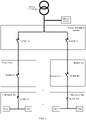
- Currently, a method for transmitting information about a power-off event in the conventional technology uses the power-off reporting technology when the power-off event occurs. For a specific schematic diagram, refer to
FIG. 1 . When a switch A1 trips due to overcurrent or leakage of electricity, meters located below the switch A1 are powered off. The meters shown inFIG. 1 are installed with PLC communication modules, in other words, all the meters affected by tripping of the A1 switch report information about a power-off event to a gateway device by using the PLC communication modules. Then, the gateway device determines a power-off area, a fault location, and the like based on the reported information about the power-off event. - However, the method for reporting the information about the power-off event in the conventional technology may have the following disadvantages: When the switch A1 is open due to a short circuit or overload of a load on a user side, if other switch devices on a same line as A1, such as B1 and C1, are open, the generated information about the power-off event cannot be transmitted to the gateway device. Consequently, the meters cannot report information about power-off events corresponding to B1 and C1 to the gateway device in the PLC communication manner.
- This application provides a method, an apparatus, and a system for information transmission in a PLC network. When a switch is open, a PLC signal may also be sent to a gateway device, and information such as power off and tripping may be reported to the gateway device.
- According to a first aspect, this application provides a switch control apparatus, including a switch and a coupling circuit, where the coupling circuit is connected in parallel to two ends of the switch. The coupling circuit is configured to: when the switch is open, transmit a first PLC signal to a gateway device.
- When the switch is open, an event such as tripping or power off may occur on the switch control apparatus. In this case, the switch control apparatus may transmit, to the gateway device through the coupling circuit, the first PLC signal sent by a PLC module of a meter located below the switch control apparatus or of another apparatus. The first PLC signal may include information such as tripping, power off, and a fault, and may further include information such as meter data and a meter log.
- With reference to the first aspect, in a first implementation of the first aspect, the switch is configured to: when the switch is closed, transmit a second PLC signal to the gateway device.
- When the switch is closed, there are two possibilities. One possibility is that both the meter and the apparatus in a PLC network work normally, and the second PLC signal is normally transmitted to the gateway device by using the switch. In this case, the second PLC signal generally carries the information such as the meter data and the meter log. Another possibility is that the event such as power off or tripping occurs on the meter located below the switch control apparatus or the another apparatus. The second PLC signal includes the information such as tripping, power off, and the fault, and may further include the information such as the meter data and the meter log.
- According to the switch control apparatus provided in this application, the coupling circuit connected in parallel to the switch is disposed, so that when the switch is open or closed, a PLC signal may be sent to the gateway device through different transmission channels, to transmit various types of information carried in the PLC signal. In this way, communication reliability of the PLC network is improved.
- With reference to the first aspect or the first implementation of the first aspect, in a second implementation of the first aspect, the switch control apparatus further includes a PLC module. The PLC module is connected in parallel to one end of the coupling circuit, and the PLC module is connected in parallel to one end of the switch. The PLC module is configured to send a third PLC signal to the gateway device.
- When the switch control apparatus includes the PLC module, the switch control apparatus has a PLC communication function. Once the event such as the fault, power off, or tripping occurs on the switch control apparatus, the switch control apparatus may send the third PLC signal to the gateway device in a timely manner, thereby improving communication efficiency. In this case, the third PLC signal may include information such as a switch status, tripping, power off, and the fault.
- With reference to any one of the first aspect, the first implementation of the first aspect, and the second implementation of the first aspect, in a third implementation of the first aspect, the coupling circuit includes a signal transformer and at least six safety capacitors. The at least six safety capacitors are configured to select a PLC signal of a specific frequency band, and the signal transformer is used to couple the selected PLC signal.
- When the switch in the switch control apparatus is open, the at least six safety capacitors may select the PLC signal of the specific frequency band, but a relatively high surge voltage is generated when the switch is open. Therefore, the selected PLC signal is coupled by using the signal transformer, so that a voltage withstand capability of the coupling circuit may be improved. In this way, reliability of the coupling circuit is improved.
- According to a second aspect, this application provides a method for information transmission. The method is applied to a first switch control apparatus, the first switch control apparatus includes a switch and a coupling circuit, and the coupling circuit is connected in parallel to two ends of the switch. The method includes: when the switch is open, transmitting a first PLC signal to a gateway device through the coupling circuit.
- With reference to the second aspect, in a first implementation of the second aspect, when the switch is closed, a second PLC signal is transmitted to the gateway device by using the switch.
- When the switch is open, an event such as tripping or power off may occur on the first switch control apparatus. In this case, the first switch control apparatus may transmit, to the gateway device through the coupling circuit, the first PLC signal sent by a PLC module of a meter located below the switch control apparatus or of another apparatus. The first PLC signal may include information such as tripping, power off, and a fault, and may further include information such as meter data and a meter log.
- When the switch is closed, there are two possibilities. One possibility is that both the meter and the apparatus in a PLC network work normally, and the second PLC signal is normally transmitted to the gateway device by using the switch. In this case, the second PLC signal generally carries the information such as the meter data and the meter log. Another possibility is that the event such as power off or tripping occurs on the meter located below the switch control apparatus or the another apparatus. The second PLC signal includes the information such as tripping, power off, and the fault, and may further include the information such as the meter data and the meter log.
- According to the method for information transmission provided in this application, when the switch is open or closed, a PLC signal may be sent to the gateway device through different transmission channels, to transmit various types of information carried in the PLC signal. In this way, communication reliability of the PLC network is improved.
- With reference to either the second aspect or the first implementation of the second aspect, in a second implementation of the first aspect, the method is applied to a second switch control apparatus. The second switch control apparatus includes a PLC module, the PLC module is connected in parallel to one end of the coupling circuit, and the PLC module is connected in parallel to one end of the switch. The method for information transmission further includes: sending a third PLC signal to the gateway device by using the PLC module, where the third PLC signal includes a first address identifier corresponding to the first switch control apparatus.
- When the switch control apparatus includes the PLC module, in other words, the switch control apparatus has a PLC communication function, once the event such as the fault, power off, or tripping occurs on the switch control apparatus, the switch control apparatus may send the third PLC signal to the gateway device in a timely manner, thereby improving communication efficiency. In this case, the third PLC signal may include information such as a switch status, tripping, power off, and the fault.
- With reference to the second implementation of the second aspect, in a third implementation of the second aspect, a first broadcast message broadcast by the second switch control apparatus may be received, where the first broadcast message includes power-off information. Then, a report message is sent to the gateway device in a unicast manner, where the report message carries a second address identifier corresponding to the second switch control apparatus. When an acknowledgment message returned by the gateway device is received, a first reply message is broadcast, where the acknowledgment message carries the second address identifier, and the first reply message carries the second address identifier.
- The first broadcast message that is broadcast by the second switch control apparatus and that includes the power-off information is received. The report message that carries the second address identifier is sent to the gateway device in the unicast manner. Then, the first reply message is broadcast by the second switch control apparatus based on the acknowledgment message returned by the gateway device. In this way, at least one switch control apparatus may determine, based on the first reply message, whether the first broadcast message including the power-off information needs to be further broadcast, so that repeated reporting of same power-off information is reduced, a bandwidth resource is saved, and information transmission efficiency is improved.
- With reference to the third implementation of the second aspect, in a fourth implementation of the second aspect, when the switch is open, a second broadcast message is broadcast, where the second broadcast message includes the first address identifier; a second reply message broadcast by a third switch control apparatus is received; and if the second address identifier exists in the second reply message, the second broadcast message is not sent; or if the second address identifier does not exist in the second reply message, the second broadcast message is broadcast.
- When the switch in the switch control apparatus is open, the second broadcast message may be broadcast to the gateway device, and the second reply message is received. Then, it is determined, based on the second reply message, whether the second broadcast message needs to be further sent, so that the repeated reporting of the same power-off information is reduced, the bandwidth resource is saved, and information transmission efficiency is improved.
- With reference to the fourth implementation of the second aspect, in a fifth implementation of the second aspect, after the second reply message broadcast by the third switch control apparatus is received, the method for information transmission in this application further includes: first receiving a third broadcast message sent by the third switch control apparatus, where the third broadcast message includes a third address identifier corresponding to the third switch control apparatus; and if the third address identifier exists in the received second reply message, not sending the third PLC signal; or if the third address identifier does not exist in the received second reply message, broadcasting the third PLC signal.
- The switch control apparatus may determine, by determining whether the third address identifier corresponding to the third switch control apparatus exists in the second reply message, whether the third PLC signal needs to be sent, so that the repeated reporting of the same power-off information is reduced, the bandwidth resource is saved, and information transmission efficiency is improved.
- According to a third aspect, this application provides a power distribution network system, including: a user meter box, a branch box, a power distribution cabinet, a gateway device, and a power transformer, where the power transformer is used to provide power supply; the user meter box includes the switch control apparatus according to any one of the first aspect and the first implementation of the first aspect to the third implementation of the first aspect; the branch box includes the switch control apparatus according to any one of the first aspect and the first implementation of the first aspect to the third implementation of the first aspect; and the power distribution cabinet includes the switch control apparatus according to any one of the first aspect and the first implementation of the first aspect to the third implementation of the first aspect.
- In the switch control apparatus provided in this application, when the switch is in an open state, the first PLC signal is transmitted to the gateway device through the coupling circuit in the switch control apparatus; or when the switch in the switch control apparatus is in a closed state, the second PLC signal is transmitted to the gateway device by using the switch in the switch control apparatus. The PLC signals all carry data information, so that the data information can be transmitted when the switch is in different states.
- In addition, in the power distribution network system of this application, when a fault occurs on the power distribution network system, in other words, when the switch is open, the first PLC signal that carries the information such as power off, tripping, or the fault may be transmitted through the coupling circuit in the switch control apparatus. In this way, the first PLC signal may be sent to the gateway device in a PLC manner, thereby improving reliability of information transmission.
-
-
FIG. 1 is a schematic diagram of an architecture of a power distribution network system in the conventional technology; -
FIG. 2 is a schematic diagram of a structure of a switch control apparatus according to an embodiment of this application; -
FIG. 3 is a schematic diagram of another structure of a switch control apparatus according to an embodiment of this application; -
FIG. 4 is a schematic diagram of still another structure of a switch control apparatus according to an embodiment of this application; -
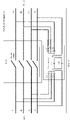
FIG. 5 is a schematic diagram of a structure of a coupling circuit in a switch control apparatus according to an embodiment of this application; -
FIG. 6 is a schematic diagram of a flow direction of a PLC signal in a switch control apparatus according to an embodiment of this application; -
FIG. 7 is a schematic diagram of an architecture of a power distribution network system according to an embodiment of this application; -
FIG. 8 is a schematic flowchart of a method for information transmission according to an embodiment of this application; -
FIG. 9 is a schematic diagram of another architecture of a power distribution network system according to an embodiment of this application; and -
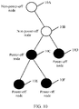
FIG. 10 is a node communication flowchart of a method for information transmission according to an embodiment of this application. - Embodiments of this application provide a method for information transmission, a switch control apparatus, and a related system, to send a first PLC signal to a gateway device, and transmit data information carried in the first PLC signal when a switch is open.
- The following describes the switch control apparatus provided in embodiments of this application.
FIG. 2 is a schematic diagram of a structure of a switch control apparatus according to an embodiment of this application. Aswitch control apparatus 200 in this embodiment of this application includes: aswitch 201 and acoupling circuit 202. - The
coupling circuit 202 is connected in parallel to two ends of theswitch 201. - The
switch 201 is configured to: when theswitch 201 is closed, transmit a first power line communication PLC signal to a gateway device. - The
coupling circuit 202 is configured to: when theswitch 201 is open, transmit a second PLC signal to the gateway device. - In this embodiment of this application, the coupling circuit is a PLC coupling circuit. It should be noted that, in an actual application, another name may be used to replace a coupling circuit that performs a same function. This is not limited in this embodiment of this application. In addition, the gateway device may be an intelligent transformer terminal unit (transformer terminal unit, TTU) or a data concentrator unit (data concentrator unit, DCU).
- It may be understood that, in an actual application, a possible reason why the
switch 201 is open is usually that the switch is tripped due to overcurrent or leakage of electricity. Another possible reason why theswitch 201 is open is that the switch is not tripped, but a line is powered off. An open state is a state in which a current cannot pass through the switch or data information cannot be transmitted by using the switch. This is not limited in this embodiment of this application. - Further, when the switch is closed, there are two possibilities. One possibility is that both a meter and an apparatus in a PLC network work normally, and the second PLC signal is normally transmitted to the gateway device by using the switch. In this case, the second PLC signal generally carries information such as meter data and a meter log. Another possibility is that an event such as power off or tripping occurs on a meter located below the switch control apparatus or another apparatus. The second PLC signal includes information such as tripping, power off, and a fault, and may further include the information such as the meter data and the meter log.
- In this embodiment of this application, when the switch in the switch control apparatus is open, a PLC signal may be transmitted to the gateway device through a transmission channel constructed by the coupling circuit. In addition, a volume of the coupling circuit is small, integration costs are relatively low, reliability of a power supply system may be improved.
- Optionally,
FIG. 3 is a schematic diagram of another structure of a switch control apparatus according to an embodiment of this application. Aswitch control apparatus 300 in this embodiment of this application includes: theswitch 301, thecoupling circuit 302, and aPLC module 303. - The
coupling circuit 302 is connected in parallel to the two ends of theswitch 301. - The
PLC module 303 is connected in parallel to one end of thecoupling circuit 302, and the PLC module is connected in parallel to a wire inlet end of theswitch 301. - The
switch 301 is configured to: when theswitch 301 is closed, transmit the first PLC signal to the gateway device. - The
coupling circuit 302 is configured to: when theswitch 301 is open, transmit the second PLC signal to the gateway device. - The
PLC module 303 is configured to send a third PLC signal to the gateway device, where the third PLC signal includes a first address identifier corresponding to a first switch control apparatus. - Specifically,
FIG. 4 is a schematic diagram of still another structure of a switch control apparatus according to an embodiment of this application. A1, A2, B1, B2, C1, and C2 are phase lines, and N is a live line. When the switch is closed, a PLC signal is transmitted from A1, B1, and C1 to A2, B2, and C2 by using the switch. When the switch is open, the PLC signal is transmitted from A1, B1, and C1 to A2, B2, and C2 through the coupling circuit. In addition, because the power line communication module is included, in other words, the switch control apparatus has a PLC communication function, the third PLC signal may be directly sent to the gateway device by using the power line communication module when the switch is in a closed state or in an open state. It may be understood thatFIG. 4 is an example of a scenario in which the PLC module is connected in parallel to the wire inlet end of the switch. In an actual application, the PLC module may alternatively be connected in parallel to a wire outlet end of the switch. - In this embodiment of this application, when the switch control apparatus includes the PLC module, in other words, the switch control apparatus has the PLC communication function, the switch control apparatus may directly report power-off information to the gateway device without waiting for the meter to report the power-off information to the gateway device, thereby improving a fault feedback speed. In this case, the third PLC signal may include information such as a switch status, tripping, power off, and the fault.
- Optionally, the
coupling circuit 202 specifically includes a signal transformer and at least six safety capacitors. - The at least six safety capacitors are configured to select a PLC signal of a specific frequency band.
- The signal transformer is used to couple the PLC signal.
- Specifically,
FIG. 5 is a schematic diagram of a structure of a coupling circuit in a switch control apparatus according to an embodiment of this application. As shown inFIG. 6 , an example in which the coupling circuit includes eight safety capacitors and two signal transformers is used to describe the switch control apparatus provided in this application. C1 to C8 are safety capacitors, T1 is a first signal transformer, T2 is a second signal transformer, A1, A2, B1, B2, C1, and C2 are phase wires, and N is a live wire. It may be understood that a switch shown inFIG. 5 is a four-pole switch. However, in an actual application, a three-pole switch may be alternatively used, and a connection manner of the three-pole switch is similar to that of the four-pole switch. Details are not described herein again. Specifically, the three-pole switch may perform an operation of a no-load line within a specific range, and the four-pole switch may improve electrical safety during electrical maintenance. Therefore, the switch in the switch control apparatus may be a switch of different types in different application scenarios, thereby improving flexibility and selectivity of this solution. - Further, the coupling circuit is connected in parallel to the switch, the safety capacitor C1 is connected to the phase line C1, the safety capacitor C2 is connected to the phase line B1, the safety capacitor C3 is connected to the phase line A1, the safety capacitor C4 is connected to the phase line C2, the safety capacitor C5 is connected to the phase line B2, the safety capacitor C6 is connected to the phase line A2, the safety capacitor C7 and the safety capacitor C8 are connected to two ends of the first signal transformer T1 and the second signal transformer T2, and N is connected to a neutral-wire busbar made from copper or a cable. When a switch contact in the switch control apparatus is closed, in other words, when the switch is in a closed state, two ends of the coupling circuit are in a short-circuit state, and a PLC signal is transmitted by using the switch in the switch control apparatus. However, when the switch contact in the switch control apparatus is open, in other words, when the switch is in an open state, the safety capacitors C1 to C3 select a PLC signal of a specific frequency band to isolate other signals. The other signals may be mains frequency alternating-current signals or other low-frequency signals. When the switch is open, a relatively high surge voltage is generated at a wire inlet end and a wire outlet end of the coupling circuit. In this case, the first signal transformer and the second signal transformer in the coupling circuit couple the PLC signal, to improve voltage withstand capabilities of the wire inlet end and the wire outlet end when the switch is open, improve reliability of the coupling circuit, and improve reliability and feasibility of this embodiment.
- Still further,
FIG. 6 is a schematic diagram of a flow direction of a PLC signal in a switch control apparatus according to an embodiment of this application. As shown inFIG. 6 , when the switch is open, the PLC signal passes through the safety capacitors C1 to C3 from the wire inlet end and is coupled to a secondary side of the transformer by using the first signal transformer T1, namely, a coil on the right side of the first signal transformer T1. Then, the PLC signal passes through the safety capacitor C7 and the safety capacitor C8 and is coupled to a secondary side of the second signal transformer T2, namely, a coil on the right side of the second signal transformer T2. Finally, the PLC signal is transmitted to the wire outlet end after passing through the safety capacitors C4 to C6, to complete transmission of the PLC signal from the wire inlet end to the wire outlet end. It may be understood that a PLC signal from a reverse direction may also be transmitted from the wire outlet end to the wire inlet end in a similar flow direction. Details are not described herein again. - When the switch in the switch control apparatus is open, the safety capacitors may select the PLC signal of the specific frequency band to be transmitted through the coupling circuit, and the relatively high surge voltage is generated when the switch is open. The transformers may couple the PLC signal, thereby improving a voltage withstand capability of the coupling circuit and improving reliability of the coupling circuit.
- The foregoing describes the switch control apparatus in embodiments of this application. The following describes a power distribution network system in embodiments of this application. For details, refer to
FIG. 7. FIG. 7 is a schematic diagram of an architecture of a power distribution network system according to an embodiment of this application. The power distribution network system includes user meter boxes, branch boxes, a power distribution cabinet, a gateway device, and a power transformer. The power transformer is used to supply power. - The user meter box includes the
switch control apparatus 200 and meters. - The branch box includes the
switch control apparatus 200. - The power distribution cabinet includes the
switch control apparatus 200. - For ease of understanding, refer to
FIG. 8. FIG. 8 is a schematic flowchart of a method for information transmission according to an embodiment of this application. Specifically,FIG. 8 is the method for information transmission based on the power distribution network system shown inFIG. 7 . A specific method is as follows. - 801: When a switch in the switch control apparatus is closed, transmit a second PLC signal to a gateway device by using the switch.
- 802: When the switch in the switch control apparatus is open, transmit a first PLC signal to the gateway device through a coupling circuit in the switch control apparatus.
- In this embodiment of this application, when the switch is open, the first PLC signal is transmitted to the gateway device through the coupling circuit. When the switch is closed, the second PLC signal is transmitted to the gateway device by using the switch.
- For example, in the power distribution network system shown in
FIG. 7 , if a switch A1 in the power distribution box is in an open state, aswitch B 1 in the branch box is in an open state, and a switch C1 in the user meter box is also in an open state, the meters on a line are powered off. In addition, first information is generated. The first information may include meter data, information about a power-off event, information about a tripping event, information about an abnormal event, user data, a message type, and address information, where the address information includes address information corresponding to the switch A1, the switch B1, and theswitch C 1. Because the switches A1, B1, and C1 are already in the open state, the first information generated by the meters cannot be transmitted by using the switches A1, B1, and C1. Therefore, after detecting the power-off event, the meters first randomly wait for a period of time, and then detect an occupation status of a channel. If the channel is occupied, in other words, the channel in a non-idle state, the meters randomly wait for a period of time, and then detect the occupation status of the channel again. If the channel is idle, the first PLC signal is transmitted to the branch box through the coupling circuit in the user meter box, then is transmitted to the power distribution cabinet through the coupling circuit in the branch box, and finally is transmitted to the gateway device through the coupling circuit in the power distribution cabinet. In this way, reporting of the first information is completed, where the first PLC signal includes the first information. - For example, in the power distribution network system shown in
FIG. 7 , if the switch A1 in the power distribution box is in a closed state, theswitch B 1 in the branch box is in the open state, and the switch C1 in the user meter box is in a closed state, the meters on the line are powered off. In addition, second information is generated. In this case, the second information may include the meter data, the information about the power-off event, the information about the tripping event, the information about the abnormal event, the user data, the message type, and the address information, where the address information includes the address information corresponding to the switch B1. Because theswitch B 1 is in the open state, the first information generated by the meters cannot be transmitted by using theswitch B 1. Therefore, the second PLC signal is transmitted to the branch box by using the switch in the user meter box, then is transmitted to the power distribution cabinet through the coupling circuit in the branch box, and finally is transmitted to the gateway device by using the switch in the power distribution cabinet. In this way, reporting of the second information is completed, where the second PLC signal includes the second information. - In this embodiment of this application, in the switch control apparatus, the information included in the PLC signals is transmitted to the gateway device through different transmission channels when the switches are in different states, thereby improving reliability and feasibility of this application.
- Next,
FIG. 9 is a schematic diagram of another architecture of a power distribution network system according to an embodiment of this application. The power distribution network system includes the user meter boxes, the branch boxes, the power distribution cabinet, the gateway device, and the power transformer. The power transformer is configured to provide power supply. - The user meter box includes the
switch control apparatus 300 and the meters. - The branch box includes the
switch control apparatus 300. - The power distribution cabinet includes the
switch control apparatus 300. - For ease of understanding, the following describes the method for information transmission based on the power distribution network system shown in
FIG. 9 . - In this embodiment of this application, a third PLC signal may be directly sent to the gateway device by using a PLC module in the switch control apparatus, and the third PLC signal includes a first address identifier corresponding to a first switch control apparatus.
- For example, in the power distribution network system shown in
FIG. 9 , if a switch A2 is in an open state, a switch B2 in the branch box is in a closed state, and a switch C2 in the user meter box is in a closed state. In this case, the meters on the line are powered off, and the first information is generated. The first information is similar to the foregoing description, and details are not described herein again. The switch A2 generates the second information. Specifically, the second information is data information generated by the switch control apparatus when the switch in the switch control apparatus is in an open state. The second information may include the information about the power-off event, the information about the tripping event, the information about the abnormal event, and the message type. Then, after the second information is generated, the third PLC signal is directly sent to the gateway device by using the PLC module. - In this embodiment of this application, when the switch control apparatus includes the PLC module, in other words, the switch control apparatus has a PLC communication function, the switch control apparatus may directly send the third PLC signal to the gateway device, thereby saving a resource for transmitting information for a plurality of times, and improving transmission efficiency. In addition, for the switch in the switch control apparatus, because a backup power unit exists in the PLC module, the switch may remain in a working state for a specific period of time after the switch is open, thereby improving reliability and feasibility of this application.
- Optionally, that the third PLC signal is sent to the gateway device by using the PLC module in the switch control apparatus may further include: receiving a first broadcast message broadcast by a second switch control apparatus, where the first broadcast message includes power-off information; sending a report message to the gateway device in a unicast manner, where the report message carries a second address identifier corresponding to the second switch control apparatus; and when an acknowledgment message returned by the gateway device is received, broadcasting a first reply message, where the acknowledgment message carries the second address identifier, and the first reply message carries the second address identifier.
- For example, refer to
FIG. 9 . The switch control apparatus that includes the power line communication module in the power distribution network system shown inFIG. 9 is used as a node. When the switch in the switch control apparatus is in the closed state, the node is a non-power-off node. When the switch in the switch control apparatus is in the open state, the node is a power-off node. - Specifically,
FIG. 10 is a node communication flowchart of a method for information transmission according to an embodiment of this application. 10A to 10F inFIG. 10 are nodes, where 10A and 10B are non-power-off nodes, and 10C to 10F are power-off nodes. It should be noted that information transmission between nodes is not classified based on a geographical location. In this embodiment of this application, signal strength is used for classification. To be specific, when the non-power-off node 10A inFIG. 10 is a gateway device, the non-power-off node 10B may be a switch control apparatus in a specific signal strength range of the gateway device. Based onFIG. 9 , it can be learned that the non-power-off node 10B may be a switch control apparatus in which the switch A1 is located, or a switch control apparatus in which theswitch B 1 is located. Specific classification of a transmission upper level and a transmission lower level between nodes is not limited herein. - Further, an example in which the non-power-
off node 10A is the gateway device is used. It can be learned from the foregoing description that a switch in the non-power-off node 10B, namely, the switch control apparatus, is in a closed state, and the non-power-off node 10B may receive the first broadcast message sent by either the power-off node 10C or the power-off node 10D. The first broadcast message may be a user datagram protocol (user datagram protocol, UDP) packet and an Internet protocol (Internet protocol, IP) packet. Therefore, the first broadcast message includes a link layer header, an IPv6 (Internet protocol version 6, the sixth generation Internet protocol) header, a UDP header, a power-off report message payload, and a link layer frame check. The IPv6 header further includes a source IPv6 address, a destination IPv6 address, and other fields in the IPv6 header. For the non-power-off node 10B, the source IPv6 address is an address corresponding to either the power-off node 10C or the power-off node 10D, and the destination IPv6 address is a broadcast address FF02:: 1. Different PLC technologies correspond to different formats of the link layer header. The format of the link layer header may be a link layer message authentication code (message authentication code, MAC) address corresponding to an IPv6 address or a short address bitmap of power-off nodes. Because when nodes access a network, the gateway device allocates a short address to each node, for example, a terminal identity document (terminal identity document, TEI). The TEI is usually of 12 bits, and the link layer header may use a TEI corresponding to the non-power-off node 10B and a TEI corresponding to the non-power-off node 10A to send the report message. The power-off report message payload may include a message type, a sequence number, a start short address, and the short address bitmap of the power-off nodes. In this embodiment of this application, a message type of the report message is power-off reporting, the start short address is a minimum value of a short address of a reporting node, and the sequence number is used to indicate a sequence number of the message. Each first broadcast message received by the non-power-off node 10B each time needs to carry a different sequence number. Because the first broadcast message may be forwarded for a plurality of times, by carrying the different sequence number, other nodes can remove a repeated message after repeatedly receiving the message. The short address bitmap of the power-off nodes is a bitmap starting from the address corresponding to either power-off node 10C or the power-off node 10D. Based on a short address of a different power-off node, a corresponding bit in the bitmap is set to "1". For example, a current maximum networking scale of an HPLC is 1024, in other words, 128 bytes are required in total, or 1024 bits are required in total. The 1024 bits may represent 1024 nodes. - Further, the non-power-
off node 10B aggregates the second address identifier in the first broadcast message. An aggregation manner may be aggregation of the second address identifier on the first address identifier or direct stacked aggregation of the second address identifier on a previous second address identifier by using a bitmap. It should be noted that in this embodiment of this application, a bitmap manner is used as an example. In an actual application, the aggregation manner of the identifier is not limited. - Specifically, the non-power-
off node 10B may then send the report message to the non-power-off node 10A, where the report message may include the link layer header, the IPv6 header, the UDP header, the power-off report message payload, and the link layer frame check. The IPv6 header further includes the source IPv6 address, the destination IPv6 address, and the other fields in the IPv6 header. For the non-power-off node 10B, the source IPv6 address is an address corresponding to the non-power-off node 10B, and the destination IPv6 address is an address corresponding to the non-power-off node 10A. The link layer header may use the TEI corresponding to the non-power-off node 10B and the TEI corresponding to the non-power-off node 10A to send the report message. The power-off report message payload may include the message type, the sequence number, the start short address, and the short address bitmap of the power-off node. In this embodiment of this application, the message type of the report message is power-off reporting, the start short address is the minimum value of the short address of the reporting node, and the sequence number is used to indicate the sequence number of the message. - Still further, when the non-power-
off node 10B receives the acknowledgment message returned by the non-power-off node 10A, the non-power-off node 10B sends the first reply message to either the power-off node 10C or the power-off node 10D. Specifically, the acknowledgment message includes the link layer header, the IPv6 header, the UDP header, the power-off report message payload, and the link layer frame check. The IPv6 header further includes the source IPv6 address, the destination IPv6 address, and the other fields in the IPv6 header. For the non-power-off node 10A, the source IPv6 address is the address corresponding to the non-power-off node 10A, the destination IPv6 address is the address corresponding to the non-power-off node 10B. The power-off report message payload may include the message type, the sequence number, the start short address, and the short address bitmap of the power-off node. A message type of the acknowledgment message is power-off acknowledgment. The first reply message includes the link layer header, the IPv6 header, the UDP header, the power-off report message payload, and the link layer frame check. The IPv6 header further includes the source IPv6 address, the destination IPv6 address, and the other fields in the IPv6 header. For the non-power-off node 10A, the source IPv6 address is the address corresponding to the non-power-off node 10B, and the destination IPv6 address is the broadcast address FF02::1. The power-off report message payload may include the message type, the sequence number, the start short address, and the short address bitmap of the power-off node. A message type of the first reply message is power-off acknowledgment. - In this embodiment of this application, when the switch in the switch control apparatus is closed, a second broadcast message sent by at least one switch control apparatus may be received, and a report message that carries the first address identifier corresponding to the second broadcast message is sent to the gateway device. Then, the first reply message that carries at least one first address identifier is sent to the at least one switch control apparatus based on the acknowledgment message sent by the gateway device, so that the at least one switch control apparatus may determine, based on the first reply message, whether to continue to send the second broadcast message. In this way, repeated reporting of same information is reduced, a bandwidth resource is saved, and information efficiency is improved.
- Optionally, that the third PLC signal is sent to the gateway device by using the PLC module in the switch control apparatus may further include: when the switch is open, broadcasting the second broadcast message, where the second broadcast message includes the first address identifier corresponding to the first switch control apparatus; receiving a second reply message broadcast by a third switch control apparatus; and if the second address identifier exists in the second reply message, not sending the second broadcast message; or if the second address identifier corresponding to the second information does not exist in the second reply information, broadcasting the second broadcast message.
- For example, refer to
FIG. 10 . The example in which the non-power-off node 10A is the gateway device is used. It can be learned from the foregoing description that the power-off node 10C, namely, the switch in the switch control apparatus, is in an open state; and then the power-off node 10C may send the second broadcast message to the non-power-off node 10B. The second broadcast message includes the link layer header, the IPv6 header, the UDP header, the power-off report message payload, and the link layer frame check. The IPv6 header further includes the source IPv6 address, the destination IPv6 address, and the other fields in the IPv6 header. For the power-off node IOC, the source IPv6 address is the address corresponding to the power-off node IOC, and the destination IPv6 address is the broadcast address FF02::1. The power-off report message payload may include the message type, the sequence number, the start short address, and the short address bitmap of the power-off node. In this embodiment of this application, a message type of the second broadcast message is power-off reporting, others are similar to the foregoing description, and details are not described herein again. - Further, when the non-power-
off node 10B receives the acknowledgment message sent by the non-power-off node 10A, the non-power-off node 10B sends the second reply message to either the power-off node 10C or the power-off node 10D. After receiving the second reply message, the power-off node 10C may determine, based on the second reply message, whether the second address identifier exists in a short address bitmap of the power-off node in the second reply message. If the second address identifier exists, the power-off node 10C does not send the second broadcast message to the non-power-off node 10B again. If the second address identifier does not exist, the power-off node 10C continues to send the second broadcast message to the non-power-off node 10B. The second reply message and the second broadcast message are similar to the foregoing description, and details are not described herein again. - In this embodiment of this application, when the switch of the switch control apparatus is open, the second broadcast information may be sent to the at least one switch control apparatus. After the at least one switch control apparatus receives the acknowledgment message sent by the gateway device, the second reply message that is sent by the at least one switch control apparatus and that carries the at least one first address identifier is received. In addition, whether the address identifier corresponding to the data information has been successfully reported to the network device is determined based on the second reply message. In this way, the repeated reporting of the same information is reduced, the bandwidth resource is saved, and information efficiency is improved.
- Optionally, after the second reply message broadcast by the third switch control apparatus is received, the method for information transmission in this embodiment of this application may further include: receiving a third broadcast message sent by the third switch control apparatus, where the third broadcast message includes a third address identifier corresponding to the third switch control apparatus; and if the third address identifier exists in the second reply message, not sending the third PLC signal; or if the third address identifier does not exist in the second reply message, broadcasting the third PLC signal.
- For example, refer to
FIG. 10 . The example in which the non-power-off node 10A is the gateway device is used. It can be learned from the foregoing description that the power-off node 10C to the power-off node 10F, namely, the switch in the switch control apparatus, are in an open state. When the power-off node 10C receives the third broadcast message sent by either the power-off node 10E or the power-off node 10F, the third broadcast message carries the link layer header, the IPv6 header, the UDP header, the power-off report message payload, and the link layer frame check. The IPv6 header further includes the source IPv6 address, the destination IPv6 address, and the other fields in the IPv6 header. For the power-off node 10C, the source IPv6 address is an address corresponding to either the power-off node 10E or the power-off node 10F, and the destination IPv6 address is the broadcast address FF02::1. The power-off report message payload may include the message type, the sequence number, the start short address, and the short address bitmap of the power-off node. In this embodiment of this application, a message type of the third broadcast message is power-off reporting. Others are similar to the foregoing description and details are not described herein again. - Further, the power-
off node 10C aggregates the third address identifier corresponding to either the power-off node 10E or the power-off node 10F by using a bitmap. Because the second reply message sent by the non-power-off node 10B has been received, the power-off node 10C may determine, based on the second reply message, whether the third address identifier corresponding to either the power-off node 10E or the power-off node 10F exists in the short address bitmap of the power-off node in the second reply message. If the third address identifier exists, the third PLC signal is not sent to the non-power-off node 10B. If the third address identifier does not exist, the third PLC signal is sent to the non-power-off node 10B. The reply message is similar to the foregoing description, and details are not described herein again. - In this embodiment of this application, after receiving the third broadcast message sent by the third switch control apparatus, the switch control apparatus determines, by determining whether the third address identifier corresponding to the third switch control apparatus exists in the second reply message, whether the third PLC signal needs to be sent. In this way, the repeated reporting of the same information is reduced, the bandwidth resource is saved, and information efficiency is improved.
- It may be clearly understood by a person skilled in the art that, for the purpose of convenient and brief description, for a detailed working process of the foregoing system, apparatus, and unit, refer to a corresponding process in the foregoing method embodiments, and details are not described herein again.
- In embodiments provided in this application, it should be understood that the disclosed system, apparatus, and method may be implemented in other manners. For example, the described apparatus embodiments are merely examples. For example, division into the units is merely logical function division and may be other division during an actual implementation. For example, a plurality of units or components may be combined or integrated into another system, or some features may be ignored or may not be performed. In addition, the displayed or discussed mutual coupling or direct coupling or communication connection may be implemented through some interfaces. Indirect coupling or communication connection between the apparatuses or units may be implemented in electrical, mechanical, or other forms.
- Units described as separate parts may or may not be physically separate, and parts displayed as units may or may not be physical units, may be located in one position, or may be distributed on a plurality of network units. Some or all of the units may be selected based on an actual requirement to achieve an objective of the solutions of embodiments.
- In addition, functional units in embodiments of this application may be integrated into one processing unit, or each of the units may exist alone physically, or two or more units are integrated into one unit. The integrated unit may be implemented in a form of hardware, or may be implemented in a form of a software functional unit.
- When the integrated unit is implemented in the form of the software functional unit and sold or used as an independent product, the integrated unit may be stored in a computer-readable storage medium. Based on such an understanding, the technical solutions of this application essentially, or the part contributing to the conventional technology, or all or some of the technical solutions may be implemented in the form of a software product. The computer software product is stored in a storage medium and includes several instructions for instructing a computer device (which may be a personal computer, a server, or a network device) to perform all or some of the steps of the methods described in embodiments of this application. The foregoing storage medium includes any medium that can store program code, such as a USB flash drive, a removable hard disk, a read-only memory (read-only memory, ROM), a random access memory (random access memory, RAM), a magnetic disk, or an optical disc.
Claims (11)
- A switch control apparatus, wherein the switch control apparatus comprises a switch and a coupling circuit, and the coupling circuit is connected in parallel to two ends of the switch; and
the coupling circuit is configured to: when the switch is open, transmit a first PLC signal to a gateway device. - The switch control apparatus according to claim 1, wherein the switch is configured to: when the switch is closed, transmit a second PLC signal to the gateway device.
- The switch control apparatus according to claim 1 or 2, wherein the switch control apparatus further comprises a PLC module, the PLC module is connected in parallel to one end of the coupling circuit, and the PLC module is connected in parallel to one end of the switch; and
the PLC module is configured to send a third PLC signal to the gateway device. - The switch control apparatus according to any one of claims 1 to 3, wherein the coupling circuit comprises a signal transformer and at least six safety capacitors;the at least six safety capacitors are configured to select a PLC signal of a specific frequency band; andthe signal transformer is configured to couple the selected PLC signal.
- A method for information transmission, wherein the method is applied to a first switch control apparatus, the first switch control apparatus comprises a switch and a coupling circuit, and the coupling circuit is connected in parallel to two ends of the switch; and the method comprises:
when the switch is open, transmitting a first PLC signal to a gateway device through the coupling circuit. - The method according to claim 5, comprising:
when the switch is closed, transmitting a second PLC signal to the gateway device by using the switch. - The method according to claim 5 or 6, wherein the method is applied to a second switch control apparatus, the second switch control apparatus comprises a PLC module, the PLC module is connected in parallel to one end of the coupling circuit, and the PLC module is connected in parallel to one end of the switch; and
the method further comprises:
sending a third PLC signal to the gateway device by using the PLC module, wherein the third PLC signal comprises a first address identifier corresponding to the first switch control apparatus. - The method according to claim 7, wherein the sending a third PLC signal to the gateway device by using the PLC module comprises:receiving a first broadcast message broadcast by the second switch control apparatus, wherein the first broadcast message comprises power-off information;sending a report message to the gateway device in a unicast manner, wherein the report message carries a second address identifier corresponding to the second switch control apparatus; andwhen an acknowledgment message returned by the gateway device is received, broadcasting a first reply message, wherein the acknowledgment message carries the second address identifier, and the reply message carries the second address identifier.
- The method according to claim 8, wherein the sending a third PLC signal to the gateway device by using the PLC module comprises:when the switch is open, broadcasting a second broadcast message, wherein the second broadcast message comprises the first address identifier;receiving a second reply message broadcast by a third switch control apparatus; andif the second address identifier exists in the second reply message, skip sending the second broadcast message; orif the second address identifier does not exist in the second reply message, broadcasting the second broadcast message.
- The method according to claim 9, wherein after the receiving a second reply message broadcast by a third switch control apparatus, the method further comprises:receiving a third broadcast message sent by the third switch control apparatus, wherein the third broadcast message comprises a third address identifier corresponding to the third switch control apparatus; andif the third address identifier exists in the second reply message, skip sending the third PLC signal; orif the third address identifier does not exist in the second reply message, broadcasting the third PLC signal.
- A power distribution network system, wherein the power distribution network system comprises a user meter box, a branch box, a power distribution cabinet, a gateway device, and a power transformer, wherein the power transformer is configured to provide power supply;the user meter box comprises the switch control apparatus according to any one of claims 1 to 4 and meters;the branch box comprises the switch control apparatus according to any one of claims 1 to 4; andthe power distribution cabinet comprises the switch control apparatus according to any one of claims 1 to 4.
Applications Claiming Priority (2)
| Application Number | Priority Date | Filing Date | Title |
|---|---|---|---|
| CN201911097619.8A CN112787686B (en) | 2019-11-11 | 2019-11-11 | A method, device and system for information transmission in a PLC network |
| PCT/CN2020/128157 WO2021093776A1 (en) | 2019-11-11 | 2020-11-11 | Method for transmitting information in plc network, apparatus, and system |
Publications (2)
| Publication Number | Publication Date |
|---|---|
| EP4037195A1 true EP4037195A1 (en) | 2022-08-03 |
| EP4037195A4 EP4037195A4 (en) | 2022-11-23 |
Family
ID=75749848
Family Applications (1)
| Application Number | Title | Priority Date | Filing Date |
|---|---|---|---|
| EP20887935.3A Pending EP4037195A4 (en) | 2019-11-11 | 2020-11-11 | METHOD FOR TRANSMITTING INFORMATION IN A NETWORK PLC, APPARATUS AND SYSTEM |
Country Status (4)
| Country | Link |
|---|---|
| US (1) | US12081285B2 (en) |
| EP (1) | EP4037195A4 (en) |
| CN (1) | CN112787686B (en) |
| WO (1) | WO2021093776A1 (en) |
Families Citing this family (2)
| Publication number | Priority date | Publication date | Assignee | Title |
|---|---|---|---|---|
| CN114357947A (en) * | 2021-12-30 | 2022-04-15 | 中电九天智能科技有限公司 | Method for planning PLC event point location distribution management system |
| CN116743306A (en) * | 2022-03-01 | 2023-09-12 | 华为技术有限公司 | Data transmission method, power line communication device and system |
Family Cites Families (30)
| Publication number | Priority date | Publication date | Assignee | Title |
|---|---|---|---|---|
| US3909821A (en) * | 1973-10-04 | 1975-09-30 | Gen Public Utilities | Communicating over power lines |
| US4300126A (en) * | 1980-04-11 | 1981-11-10 | General Electric Co. | Method and apparatus, for power line communications using zero crossing load interruption |
| US4686382A (en) * | 1985-08-14 | 1987-08-11 | Westinghouse Electric Corp. | Switch bypass circuit for power line communication systems |
| US6480510B1 (en) * | 1998-07-28 | 2002-11-12 | Serconet Ltd. | Local area network of serial intelligent cells |
| US6549616B1 (en) * | 2000-03-20 | 2003-04-15 | Serconet Ltd. | Telephone outlet for implementing a local area network over telephone lines and a local area network using such outlets |
| US7245472B2 (en) * | 2001-05-18 | 2007-07-17 | Curretn Grid, Llc | Medium voltage signal coupling structure for last leg power grid high-speed data network |
| JP2006506016A (en) * | 2002-11-06 | 2006-02-16 | アンビエント・コーポレイション | Capacitive coupler for power line communication |
| US7308103B2 (en) * | 2003-05-08 | 2007-12-11 | Current Technologies, Llc | Power line communication device and method of using the same |
| US7321291B2 (en) * | 2004-10-26 | 2008-01-22 | Current Technologies, Llc | Power line communications system and method of operating the same |
| US7405652B2 (en) * | 2004-09-21 | 2008-07-29 | Abet Technologies, Llc | Communication and AC power system |
| US7873058B2 (en) * | 2004-11-08 | 2011-01-18 | Mosaid Technologies Incorporated | Outlet with analog signal adapter, a method for use thereof and a network using said outlet |
| US8040235B2 (en) * | 2005-04-08 | 2011-10-18 | Panasonic Corporation | Relay apparatus and electric appliance |
| US7307510B2 (en) * | 2005-09-02 | 2007-12-11 | Current Technologies, Llc | Power meter bypass device and method for a power line communications system |
| US7813842B2 (en) * | 2006-03-09 | 2010-10-12 | Sony Corporation | Systems and methods for use in providing local power line communication |
| US7761079B2 (en) * | 2006-06-09 | 2010-07-20 | Current Technologies, Llc | Power line communication device and method |
| JP2008227885A (en) * | 2007-03-13 | 2008-09-25 | Yamaha Corp | Transmission line structure for power line communication and power line opener/closer |
| CN102106054A (en) * | 2007-03-22 | 2011-06-22 | 鲍尔马特有限公司 | Signal transfer system |
| US7795994B2 (en) * | 2007-06-26 | 2010-09-14 | Current Technologies, Llc | Power line coupling device and method |
| US20090085726A1 (en) * | 2007-09-27 | 2009-04-02 | Radtke William O | Power Line Communications Coupling Device and Method |
| WO2011093094A1 (en) * | 2010-01-29 | 2011-08-04 | パナソニック株式会社 | Vehicle charging device and vehicle charging system using same |
| CN102227090B (en) * | 2011-06-27 | 2013-08-21 | 山西省电力公司临汾供电分公司 | 10kV Carrier Communication Intelligent Feeder Automation System |
| AU2013239344A1 (en) | 2012-03-28 | 2014-10-09 | Xped Holdings Pty Ltd | Method and apparatus for forming associations and communicating between devices |
| US10354520B2 (en) * | 2012-12-17 | 2019-07-16 | Itron, Inc. | Power line communication over disconnected service lines |
| EP2852069A1 (en) * | 2013-09-24 | 2015-03-25 | ABB Research Ltd. | System for transmitting and receiving a power line communication signal over the power bus of a power electronic converter |
| WO2015136682A1 (en) * | 2014-03-14 | 2015-09-17 | 株式会社日立製作所 | Electricity storage system |
| US10348094B2 (en) * | 2015-01-28 | 2019-07-09 | Abb Schweiz Ag | Energy panel arrangement shutdown |
| US10454529B2 (en) * | 2016-01-08 | 2019-10-22 | Qorvo Us, Inc. | RF branch with improved power handling |
| IT201600105056A1 (en) * | 2016-10-19 | 2018-04-19 | St Microelectronics Srl | COUPLING CIRCUIT FOR TRANSMISSION ON POWER SUPPLY, DEVICE, NETWORK AND CORRESPONDENT PROCEDURE LINES |
| CN106656271B (en) * | 2016-11-27 | 2023-07-21 | 西安科技大学高新学院 | A carrier communication current loop signal coupling device |
| CN110300039B (en) * | 2018-03-23 | 2020-12-15 | 华为技术有限公司 | Network access method, agent coordination device and site device for hybrid networking |
-
2019
- 2019-11-11 CN CN201911097619.8A patent/CN112787686B/en active Active
-
2020
- 2020-11-11 EP EP20887935.3A patent/EP4037195A4/en active Pending
- 2020-11-11 WO PCT/CN2020/128157 patent/WO2021093776A1/en not_active Ceased
-
2022
- 2022-05-11 US US17/741,443 patent/US12081285B2/en active Active
Also Published As
| Publication number | Publication date |
|---|---|
| CN112787686B (en) | 2025-10-14 |
| CN112787686A (en) | 2021-05-11 |
| US20220271795A1 (en) | 2022-08-25 |
| WO2021093776A1 (en) | 2021-05-20 |
| EP4037195A4 (en) | 2022-11-23 |
| US12081285B2 (en) | 2024-09-03 |
Similar Documents
| Publication | Publication Date | Title |
|---|---|---|
| Sidhu et al. | Control and automation of power system substation using IEC61850 communication | |
| Garau et al. | A 5G cellular technology for distributed monitoring and control in smart grid | |
| US10355523B2 (en) | Power distribution terminal capable of determining fault type and determination method thereof | |
| US9478973B2 (en) | Method for transfer of control between devices in a substation system and a device thereof | |
| US9021067B2 (en) | Determining VLAN-IDs for a switched-based communication network of a process control system | |
| US12081285B2 (en) | Method, apparatus, and system for information transmission in PLC network | |
| US11228521B2 (en) | Systems and method for detecting failover capability of a network device | |
| Lu et al. | On network performance evaluation toward the smart grid: A case study of DNP3 over TCP/IP | |
| US20140022886A1 (en) | Proxy maintenance endpoint at provider edge switch | |
| CN112510819A (en) | Power network operation data monitoring system | |
| CN111541463A (en) | Dynamic media switching in co-located PLC and RF networks | |
| Aydeger et al. | SDN-enabled recovery for Smart Grid teleprotection applications in post-disaster scenarios | |
| CN111869044B (en) | Realize communication between substation communication equipment | |
| CN108259264A (en) | Test method, the device and system of the network equipment | |
| CN107483084B (en) | Broadband carrier networking method, site and system | |
| EP2811606B1 (en) | System for a circuit breaker control | |
| Rinaldi et al. | An application of IEEE 802.11 ac to Smart Grid automation based on IEC 61850 | |
| Alsharbaty et al. | An enhanced industrial wireless communication network for hard real time performance substation automation purposes | |
| CN107241745A (en) | Build the methods, devices and systems of network | |
| CN113162656A (en) | Low-voltage distribution station area communication network applying HPLC communication sub-network | |
| Zerihun et al. | Performance evaluation of iec 61850 goose messages over a 5g network for protection coordination in smart grid | |
| CN118472937A (en) | Main-distribution cooperative power grid power supply recovery method and device | |
| EP4036527B1 (en) | Utility meter with short and long-range radios with intelligent switching therebetween | |
| CN110518466A (en) | A kind of Intelligent distribution switchgear and Internet of Things network method | |
| Bavarian et al. | Leveraging the smart metering infrastructure in distribution automation |
Legal Events
| Date | Code | Title | Description |
|---|---|---|---|
| STAA | Information on the status of an ep patent application or granted ep patent |
Free format text: STATUS: THE INTERNATIONAL PUBLICATION HAS BEEN MADE |
|
| PUAI | Public reference made under article 153(3) epc to a published international application that has entered the european phase |
Free format text: ORIGINAL CODE: 0009012 |
|
| STAA | Information on the status of an ep patent application or granted ep patent |
Free format text: STATUS: REQUEST FOR EXAMINATION WAS MADE |
|
| 17P | Request for examination filed |
Effective date: 20220428 |
|
| AK | Designated contracting states |
Kind code of ref document: A1 Designated state(s): AL AT BE BG CH CY CZ DE DK EE ES FI FR GB GR HR HU IE IS IT LI LT LU LV MC MK MT NL NO PL PT RO RS SE SI SK SM TR |
|
| A4 | Supplementary search report drawn up and despatched |
Effective date: 20221025 |
|
| RIC1 | Information provided on ipc code assigned before grant |
Ipc: H04B 3/56 20060101ALI20221019BHEP Ipc: H02J 13/00 20060101ALI20221019BHEP Ipc: H04B 3/54 20060101AFI20221019BHEP |
|
| DAV | Request for validation of the european patent (deleted) | ||
| DAX | Request for extension of the european patent (deleted) | ||
| STAA | Information on the status of an ep patent application or granted ep patent |
Free format text: STATUS: EXAMINATION IS IN PROGRESS |
|
| 17Q | First examination report despatched |
Effective date: 20250221 |