EP4037070B1 - Battery pack, electronic device comprising same, and vehicle - Google Patents
Battery pack, electronic device comprising same, and vehicle Download PDFInfo
- Publication number
- EP4037070B1 EP4037070B1 EP21795658.0A EP21795658A EP4037070B1 EP 4037070 B1 EP4037070 B1 EP 4037070B1 EP 21795658 A EP21795658 A EP 21795658A EP 4037070 B1 EP4037070 B1 EP 4037070B1
- Authority
- EP
- European Patent Office
- Prior art keywords
- mounting plate
- refrigerant
- battery pack
- battery
- plate
- Prior art date
- Legal status (The legal status is an assumption and is not a legal conclusion. Google has not performed a legal analysis and makes no representation as to the accuracy of the status listed.)
- Active
Links
Images


Classifications
-
- H—ELECTRICITY
- H01—ELECTRIC ELEMENTS
- H01M—PROCESSES OR MEANS, e.g. BATTERIES, FOR THE DIRECT CONVERSION OF CHEMICAL ENERGY INTO ELECTRICAL ENERGY
- H01M10/00—Secondary cells; Manufacture thereof
- H01M10/60—Heating or cooling; Temperature control
- H01M10/65—Means for temperature control structurally associated with the cells
- H01M10/655—Solid structures for heat exchange or heat conduction
- H01M10/6556—Solid parts with flow channel passages or pipes for heat exchange
-
- H—ELECTRICITY
- H01—ELECTRIC ELEMENTS
- H01M—PROCESSES OR MEANS, e.g. BATTERIES, FOR THE DIRECT CONVERSION OF CHEMICAL ENERGY INTO ELECTRICAL ENERGY
- H01M10/00—Secondary cells; Manufacture thereof
- H01M10/60—Heating or cooling; Temperature control
- H01M10/61—Types of temperature control
- H01M10/613—Cooling or keeping cold
-
- H—ELECTRICITY
- H01—ELECTRIC ELEMENTS
- H01M—PROCESSES OR MEANS, e.g. BATTERIES, FOR THE DIRECT CONVERSION OF CHEMICAL ENERGY INTO ELECTRICAL ENERGY
- H01M10/00—Secondary cells; Manufacture thereof
- H01M10/60—Heating or cooling; Temperature control
- H01M10/62—Heating or cooling; Temperature control specially adapted for specific applications
- H01M10/623—Portable devices, e.g. mobile telephones, cameras or pacemakers
-
- H—ELECTRICITY
- H01—ELECTRIC ELEMENTS
- H01M—PROCESSES OR MEANS, e.g. BATTERIES, FOR THE DIRECT CONVERSION OF CHEMICAL ENERGY INTO ELECTRICAL ENERGY
- H01M10/00—Secondary cells; Manufacture thereof
- H01M10/60—Heating or cooling; Temperature control
- H01M10/62—Heating or cooling; Temperature control specially adapted for specific applications
- H01M10/625—Vehicles
-
- H—ELECTRICITY
- H01—ELECTRIC ELEMENTS
- H01M—PROCESSES OR MEANS, e.g. BATTERIES, FOR THE DIRECT CONVERSION OF CHEMICAL ENERGY INTO ELECTRICAL ENERGY
- H01M10/00—Secondary cells; Manufacture thereof
- H01M10/60—Heating or cooling; Temperature control
- H01M10/64—Heating or cooling; Temperature control characterised by the shape of the cells
- H01M10/647—Prismatic or flat cells, e.g. pouch cells
-
- H—ELECTRICITY
- H01—ELECTRIC ELEMENTS
- H01M—PROCESSES OR MEANS, e.g. BATTERIES, FOR THE DIRECT CONVERSION OF CHEMICAL ENERGY INTO ELECTRICAL ENERGY
- H01M10/00—Secondary cells; Manufacture thereof
- H01M10/60—Heating or cooling; Temperature control
- H01M10/65—Means for temperature control structurally associated with the cells
- H01M10/656—Means for temperature control structurally associated with the cells characterised by the type of heat-exchange fluid
- H01M10/6567—Liquids
- H01M10/6568—Liquids characterised by flow circuits, e.g. loops, located externally to the cells or cell casings
-
- H—ELECTRICITY
- H01—ELECTRIC ELEMENTS
- H01M—PROCESSES OR MEANS, e.g. BATTERIES, FOR THE DIRECT CONVERSION OF CHEMICAL ENERGY INTO ELECTRICAL ENERGY
- H01M50/00—Constructional details or processes of manufacture of the non-active parts of electrochemical cells other than fuel cells, e.g. hybrid cells
- H01M50/20—Mountings; Secondary casings or frames; Racks, modules or packs; Suspension devices; Shock absorbers; Transport or carrying devices; Holders
- H01M50/204—Racks, modules or packs for multiple batteries or multiple cells
-
- H—ELECTRICITY
- H01—ELECTRIC ELEMENTS
- H01M—PROCESSES OR MEANS, e.g. BATTERIES, FOR THE DIRECT CONVERSION OF CHEMICAL ENERGY INTO ELECTRICAL ENERGY
- H01M50/00—Constructional details or processes of manufacture of the non-active parts of electrochemical cells other than fuel cells, e.g. hybrid cells
- H01M50/20—Mountings; Secondary casings or frames; Racks, modules or packs; Suspension devices; Shock absorbers; Transport or carrying devices; Holders
- H01M50/244—Secondary casings; Racks; Suspension devices; Carrying devices; Holders characterised by their mounting method
-
- H—ELECTRICITY
- H01—ELECTRIC ELEMENTS
- H01M—PROCESSES OR MEANS, e.g. BATTERIES, FOR THE DIRECT CONVERSION OF CHEMICAL ENERGY INTO ELECTRICAL ENERGY
- H01M50/00—Constructional details or processes of manufacture of the non-active parts of electrochemical cells other than fuel cells, e.g. hybrid cells
- H01M50/20—Mountings; Secondary casings or frames; Racks, modules or packs; Suspension devices; Shock absorbers; Transport or carrying devices; Holders
- H01M50/247—Mountings; Secondary casings or frames; Racks, modules or packs; Suspension devices; Shock absorbers; Transport or carrying devices; Holders specially adapted for portable devices, e.g. mobile phones, computers, hand tools or pacemakers
-
- H—ELECTRICITY
- H01—ELECTRIC ELEMENTS
- H01M—PROCESSES OR MEANS, e.g. BATTERIES, FOR THE DIRECT CONVERSION OF CHEMICAL ENERGY INTO ELECTRICAL ENERGY
- H01M50/00—Constructional details or processes of manufacture of the non-active parts of electrochemical cells other than fuel cells, e.g. hybrid cells
- H01M50/20—Mountings; Secondary casings or frames; Racks, modules or packs; Suspension devices; Shock absorbers; Transport or carrying devices; Holders
- H01M50/249—Mountings; Secondary casings or frames; Racks, modules or packs; Suspension devices; Shock absorbers; Transport or carrying devices; Holders specially adapted for aircraft or vehicles, e.g. cars or trains
-
- H—ELECTRICITY
- H01—ELECTRIC ELEMENTS
- H01M—PROCESSES OR MEANS, e.g. BATTERIES, FOR THE DIRECT CONVERSION OF CHEMICAL ENERGY INTO ELECTRICAL ENERGY
- H01M50/00—Constructional details or processes of manufacture of the non-active parts of electrochemical cells other than fuel cells, e.g. hybrid cells
- H01M50/20—Mountings; Secondary casings or frames; Racks, modules or packs; Suspension devices; Shock absorbers; Transport or carrying devices; Holders
- H01M50/258—Modular batteries; Casings provided with means for assembling
-
- H—ELECTRICITY
- H01—ELECTRIC ELEMENTS
- H01M—PROCESSES OR MEANS, e.g. BATTERIES, FOR THE DIRECT CONVERSION OF CHEMICAL ENERGY INTO ELECTRICAL ENERGY
- H01M2220/00—Batteries for particular applications
- H01M2220/20—Batteries in motive systems, e.g. vehicle, ship, plane
-
- H—ELECTRICITY
- H01—ELECTRIC ELEMENTS
- H01M—PROCESSES OR MEANS, e.g. BATTERIES, FOR THE DIRECT CONVERSION OF CHEMICAL ENERGY INTO ELECTRICAL ENERGY
- H01M2220/00—Batteries for particular applications
- H01M2220/30—Batteries in portable systems, e.g. mobile phone, laptop
-
- Y—GENERAL TAGGING OF NEW TECHNOLOGICAL DEVELOPMENTS; GENERAL TAGGING OF CROSS-SECTIONAL TECHNOLOGIES SPANNING OVER SEVERAL SECTIONS OF THE IPC; TECHNICAL SUBJECTS COVERED BY FORMER USPC CROSS-REFERENCE ART COLLECTIONS [XRACs] AND DIGESTS
- Y02—TECHNOLOGIES OR APPLICATIONS FOR MITIGATION OR ADAPTATION AGAINST CLIMATE CHANGE
- Y02E—REDUCTION OF GREENHOUSE GAS [GHG] EMISSIONS, RELATED TO ENERGY GENERATION, TRANSMISSION OR DISTRIBUTION
- Y02E60/00—Enabling technologies; Technologies with a potential or indirect contribution to GHG emissions mitigation
- Y02E60/10—Energy storage using batteries
Definitions
- the present disclosure relates to a battery module, a battery pack comprising the same, an electric device and a vehicle, and more particularly, to a battery pack with reduced manufacturing cost and improved safety by a simplified assembly process with the reduced number of components.
- a lithium secondary battery primarily uses a lithium-based oxide and a carbon material as a positive electrode active material and a negative electrode active material respectively. Additionally, the lithium secondary battery includes an electrode assembly including a positive electrode plate and a negative electrode plate coated with the positive electrode active material and the negative electrode active material respectively with a separator interposed between the positive electrode plate and the negative electrode plate, and a packaging or a battery case in which the electrode assembly is hermetically received together with an electrolyte solution.
- lithium secondary batteries may be classified into can-type secondary batteries including the electrode assembly embedded in a metal can and pouch-type secondary batteries including the electrode assembly embedded in a pouch of an aluminum laminate sheet according to the shape of the packaging.
- the large capacity battery packs are prone to heat accumulation since a plurality of secondary batteries is charged and discharged, and to increase the service life of the battery packs, effective cooling is necessary. Accordingly, in general, the large capacity battery packs have separate cooling members having pack-scale large cooling capability.
- the material cost and the assembly cost increase in the process of separately manufacturing the cooling member having pack-scale large cooling capability and coupling it to the battery pack, and the high volume of the cooling member reduces the energy density of the battery pack.
- the battery packs mounted in vehicles need to respond to large impacts in the event of vehicle collisions. Accordingly, the battery packs need to solve the problem with damage of the internal components caused by external impacts or fires or explosions in the secondary battery. In particular, when the cooling members are damaged, refrigerants leak in the cooling members, causing electric short circuits between battery modules.
- the present disclosure is designed to solve the above-described problem, and therefore the present disclosure is directed to providing a battery pack with reduced manufacturing cost and improved safety by a simplified assembly process with the reduced number of components.
- a battery pack according to the present disclosure includes a plurality of battery modules, and a tray including a mounting plate which extends horizontally so that the plurality of battery modules is mounted on the mounting plate.
- the mounting plate includes a feed pipe disposed on one side and configured to receive a refrigerant from outside, and a discharge pipe disposed on the other side of the mounting plate and configured to discharge the refrigerant to the outside, and the mounting plate includes a plurality of refrigerant channels, each refrigerant channel extending from one side to the other side and being in communication with the feed pipe or the discharge pipe,.
- the battery module includes an inlet configured to feed the refrigerant into the battery module, and an outlet configured to discharge the refrigerant out of the battery module.
- the mounting plate includes an inlet port connected with the inlet to feed the refrigerant from the refrigerant channel to the battery module, and an outlet port connected with the outlet to discharge the refrigerant from the battery module to the refrigerant channel.
- the inlet port and the outlet port may include a post which extends upward from an upper surface of the mounting plate, a ring gasket fixed to a part of the post, and a support gasket spaced a predetermined distance apart from the post and configured to come into close contact with a perimeter of the inlet or the outlet of the battery module.
- the tray may further include a front frame coupled to a front end of the mounting plate and having a plate shape standing vertically, a rear frame coupled to a rear end of the mounting plate and having a plate shape standing vertically, a pair of side covers having two ends which extend in one direction, the two extended ends being coupled with the front frame and the rear frame respectively, and a base plate having a plate shape extending horizontally and configured to be coupled with a bottom of the mounting plate.
- the mounting plate may include a mounting portion having a plate shape extending horizontally so that the plurality of battery modules is mounted on the mounting portion, a coupling portion which extends downward from a lower surface of the mounting portion, extends one side of the mounting portion to the other side and has a bottom coupled with the base plate, and a joining portion at which the refrigerant channel and the base plate are coupled.
- the side cover may include a pipe receiving portion of which an outer wall is configured to cover at least part of the feed pipe or the discharge pipe to receive the feed pipe or the discharge pipe.
- the tray may include a temporary storage configured such that when the refrigerant leaks in the feed pipe or the discharge pipe, the leaking refrigerant may flow into temporary storage.
- the temporary storage may be an empty space between the mounting plate and the base plate.
- an electronic device includes at least one battery pack.
- a vehicle according to the present disclosure includes at least one battery pack.
- the mounting plate includes the feed pipe disposed on one side and configured to receive the refrigerant from the outside, and the discharge pipe disposed on the other side of the mounting plate and configured to discharge the refrigerant to the outside, and the mounting plate includes the plurality of refrigerant channels, each extending from one side to the other side and being in communication with the feed pipe or the discharge pipe, and thus as opposed to the conventional battery pack, there is no separate cooling member, and the mounting plate of the tray on which the plurality of battery modules is mounted includes the feed pipe, the discharge pipe and the refrigerant channels, so the cooling member is integrally formed on the structure of a part of the mounting plate, thereby eliminating the need to separately manufacture the cooling member, and further, eliminating the need to couple or assemble the separate cooling member with the mounting plate. Accordingly, it is possible to reduce the manufacturing cost of the battery pack, and reducing the heat conduction path of the battery modules mounted and the refrigerant channels, thereby increasing the cooling efficiency.
- the side cover includes the pipe receiving portion configured such that the outer wall covers at least part of the feed pipe or the discharge pipe to receive the feed pipe or the discharge pipe, so the side covers covers the feed pipe or the discharge pipe to protect it, thereby preventing the feed pipe or the discharge pipe from being damaged by external impacts.
- the refrigerant may be fed from an external device into an inlet P3 of the front end part of the feed pipe 351.
- the feed pipe 351 may be configured to supply the refrigerant to a refrigerant channel 323a1 of the mounting plate 323 as described below.
- the temperature increased refrigerant may move from a refrigerant channel 323a2 of the mounting plate 323 to the discharge pipe 353, and the refrigerant may move to the external device through an outlet P4 of the front end part of the discharge pipe 353.
- the refrigerant channels 323a may extend from one side of the mounting plate 323 to the other side.
- the refrigerant channels 323a may extend from the right end of the mounting plate 323 to the left end.
- the mounting plate 323 includes the feed pipe 351 disposed on one side and configured to receive the refrigerant from the outside, and the discharge pipe 353 disposed on the other side of the mounting plate 323 and configured to discharge the refrigerant to the outside, and the mounting plate 323 includes the plurality of refrigerant channels 323a, each extending from one side to the other side and being in communication with the feed pipe 351 or the discharge pipe 353, and thus as opposed to the conventional battery pack 300, there is no separate cooling member, and the mounting plate 323 of the tray 320 on which the plurality of battery modules 200 is mounted includes the feed pipe 351, the discharge pipe 353 and the refrigerant channels 323a, so the cooling member is integrally formed on the structure of a part of the mounting plate, thereby eliminating the need to separately manufacture the cooling member, and further, eliminating the need to couple or assemble the separate cooling member with the mounting plate. Accordingly, it is possible to reduce the manufacturing cost of the battery pack, and reducing the heat conduction path of the
- the refrigerant channel 323a1 is in communication with the feed pipe 351 and the remaining refrigerant channel 323a2 is in communication with the discharge pipe 353, thereby simplifying the cooling structure. Accordingly, it is easy to manufacture the battery pack 300.
- FIGS. 5 and 6 are bottom views schematically showing the battery modules of the battery pack according to an embodiment of the present disclosure.
- the battery module 200A includes an inlet P1 and an outlet P2.
- the inlet P1 is configured to supply the refrigerant to the battery module 200A.
- the inlet P1 may be in communication with the refrigerant channel 323a1 connected with the feed pipe 351 of the mounting plate 323.
- the outlet P2 is configured to allow the refrigerant to exit the battery module 200A.
- the outlet P2 may be in communication with the refrigerant channel 323a2 connected to the discharge pipe 353 of the mounting plate 323.
- the battery module 200A disposed in the first row may have the inlet P1 and the outlet P2 on the left side of the lower surface of the battery module 200 as shown in FIG. 5 .
- the battery module 200B disposed in the second row may have the inlet P1 and the outlet P2 on the right side of the lower surface of the battery module 200 as shown in FIG. 6 .
- the battery module 200 may include a separate cooling member (not shown) configured to cool the plurality of secondary batteries in the battery module 200 using the refrigerant fed through the inlet P1.
- the cooling member may be a heat sink. After the temperature of the refrigerant fed into the cooling member is increased, the cooling member may discharge the temperature increased refrigerant through the outlet P2.
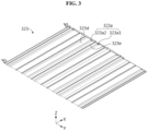
- FIG. 7 is a partial perspective view schematically showing the mounting plate of the battery pack according to an embodiment of the present disclosure.
- the mounting plate 323 includes an inlet port 323b and an outlet port 323c.
- the inlet port 323b is connected with the inlet P1 to feed the refrigerant from the refrigerant channel 323a to the battery module 200.
- the outlet port 323c is configured to discharge the refrigerant from the battery module 200 to the refrigerant channel 323a.
- the battery module 200 has the inlet P1 and the outlet P2 and the mounting plate 323 has the inlet port 323b and the outlet port 323c, thereby smoothly moving the refrigerant fed into the refrigerant channel 323a of the mounting plate 323 into the battery modules 200.
- the inlet port 323b may include a post 323b2, a ring gasket 323b3 and a support gasket 323b4.
- the post 323b2 may extend upward from the upper surface of the mounting plate 323 (in the positive Z axis direction of FIG. 2 ).
- the post 323b2 may be in the shape of a hollow circular tube.
- the ring gasket 323b3 may be fixed to a part of the post 323b2.
- the post 323b2 may have a fixing groove (not shown) of which the periphery extends inward. A part of the ring gasket 323b3 may be inserted into the fixing groove.
- the support gasket 323b4 may be spaced a predetermined distance apart from the post 323b2.
- the support gasket 323b4 may be in the shape of a ring.
- the support gasket 323b4 may be configured to come into close contact with the perimeter of the inlet P1 of the battery module 200.
- the support gasket 323b4 may be configured to support up the lower surface of the battery module 200.
- the outlet port 323c may include a post 323c2, a ring gasket 323c3 and a support gasket 323c4.
- the post 323c2 may extend upward from the upper surface of the mounting plate 323.
- the post 323c2 may be in the shape of a hollow circular tube.
- the ring gasket 323c3 may be fixed to a part of the post 323c2.
- the post 323c2 may have a fixing groove of which the periphery extends inward. A part of the ring gasket 323c3 may be inserted into the fixing groove.
- the support gasket 323c4 may be spaced a predetermined distance apart from the post 323c2.
- the support gasket 323c4 may be in the shape of a ring.
- the support gasket 323c4 may be configured to come into close contact with the perimeter of the outlet P2 of the battery module 200.
- the support gasket 323c4 may be configured to support up the lower surface of the battery module 200.
- each of the inlet port 323b and the outlet port 323c includes the post 323b2, the ring gasket 323b3, and the support gasket 323b4, thereby performing two-step sealing using two gaskets. Accordingly, the present disclosure may prevent the refrigerant from leaking in the process of feeding the refrigerant from the refrigerant channel 323a into the battery module 200 or the process of discharging the refrigerant from the battery module 200 to the refrigerant channel 323a.
- FIG. 8 is a partial bottom view schematically showing the battery module of the battery pack according to an embodiment of the present disclosure.
- the tray 320 may further include a front frame 325, a rear frame 326, a pair of side covers 330 and a base plate 324.
- the front frame 325 may be coupled to the front end of the mounting plate 323.
- the front frame 325 may be in the shape of a plate that stands vertically.
- the front frame 325 may serve as a front wall of the tray 320.
- the rear frame 326 may be coupled to the rear end of the mounting plate 323.
- the rear frame 326 may be in the shape of a plate that stands vertically.
- the rear frame 326 may serve as a rear wall of the tray 320.
- the side covers 330 may extend in one direction.
- the side covers 330 may be formed by extrusion molding.
- the front ends of the side covers 330 may be coupled with the front frame 325.
- the rear ends of the side covers 330 may be coupled with the rear frame 326.
- the side covers 330 may be disposed at one side and the other side of the mounting plate 323 of the tray 320 respectively.
- the two side covers 330 may include body portions 333 disposed at the left end and the right end of the mounting plate 323 respectively.
- the body portions 333 may serve as left and right side walls of the battery pack 300.
- the body portions 333 may extend in the front and rear direction.
- the body portion 333 may be in the shape of a plate formed by extrusion molding in the front and rear direction.
- the body portions 333 may stand in the up and down direction.
- the body portions 333 may be in the shape of a hollow plate.
- the base plate 324 may be in the shape of a plate that extends horizontally.
- the base plate 324 may have a size corresponding to the mounting plate 323.
- the base plate 324 may be coupled with the bottom of the mounting plate 323.
- the tray 320 of the present disclosure includes the front frame 325, the rear frame 326, the pair of side covers 330 and the base plate 324, the coupling structure of the front frame 325, the rear frame 326, the pair of side covers 330, the mounting plate 323 and the base plate 324 can effectively protect the internal components from external impacts in the left and right direction and the front and rear direction. Ultimately, it is possible to increase the safety of the battery pack 300 of the present disclosure.
- the mounting plate 323 may include a mounting portion 323d and a coupling portion 323e.
- the mounting portion 323d may be in the shape of a plate that extends horizontally so that the plurality of battery modules 200 is mounted on the mounting portion 323d.
- the coupling portion 323e may extend downward from the lower surface of the mounting portion 323d (in the negative Z axis direction of FIG. 2 ).
- the coupling portion 323e may include a down extended portion and a horizontal extended portion.
- the down extended portion and the horizontal extended portion may extend from one side to the other side along the lower surface of the mounting portion 323d.
- the coupling portion 323e may extend from the right end of the mounting plate 323 to the left end.
- the coupling method may use friction stir welding.
- the friction stir welding refers to a welding process that uses a non-consumable tool having a screw thread shaped protrusion to join two facing pieces of a material. When the tool is inserted into the material while rotating at a high speed, heat is generated by friction between the tool and the material, a region of the material near the tool is softened by the frictional heat and materials on both sides of the joint surface are forcibly intermixed by the plastic flow of the material by stir of the tool.
- the mounting plate 323 extends downward from the lower surface of the mounting portion 323d and has the coupling portion 323e which extends from one side of the mounting portion 323d to the other side and is coupled with the base plate 324 on the bottom, thereby effectively improving the joining strength between the mounting plate 323 and the base plate 324.
- the mounting plate 323 may include a joining portion 323f at which the lower surface of the refrigerant channel 323a is coupled with the upper surface of the base plate 324.
- friction stir welding may be used.
- the cooling member including the separate refrigerant channel 323a according to the conventional art is not stably coupled to the mounting plate 323, the cooling member may be damaged due to interference in the process of coupling the mounting plate 323 and the base plate 324. Accordingly, the size of the cooling member may be reduced to prevent interference with the base plate 324, but when the size of the cooling member is reduced, the cooling efficiency of the battery pack 300 reduces.
- the present disclosure forms the refrigerant channel 323a in the mounting plate 323 itself and directly couples the refrigerant channel 323a with the upper surface of the base plate 324, thereby effectively increasing the coupling area between the mounting plate 323 and the base plate 324. Further, it is possible to solve the problem with a decline in cooling capability resulting from the reduced refrigerant channel 323a by maximizing the size of the refrigerant channel 323a in a space between the mounting plate 323 and the base plate 324.
- the side cover 330 may include a pipe receiving portion 339 configured to cover at least part of the feed pipe 351 to receive the feed pipe 351.
- the side cover 330 may include the pipe receiving portion 339 configured to cover at least part of the discharge pipe 353 to receive the discharge pipe 353.
- the pipe receiving portion 339 may be a space formed such that the outer wall covers at least part of the cooling pipe 350.
- the pipe receiving portion 339 may include a portion 339a of which the outer wall extends inward (rightward) from the inner surface of the body portion 333, and a remaining portion 339b which is bent and extends downward from the end portion of the extended portion 339a.
- the side cover 330 includes the pipe receiving portion 339 configured such that the outer wall covers at least part of the feed pipe 351 or the discharge pipe 353 to receive the feed pipe 351 or the discharge pipe 353, so the side covers 330 covers the feed pipe 351 or the discharge pipe 353 to protect it, thereby preventing the feed pipe 351 or the discharge pipe 353 from being damaged by external impacts.
- the tray 320 may include a temporary storage 327.
- the temporary storage 327 may be configured to allow the leaking refrigerant to flow into the temporary storage 327 when the refrigerant leaks in the cooling pipe 350.
- the temporary storage 327 may be formed in a space between the mounting plate 323 and the base plate 324.
- the end portion 323a of the mounting plate 323 may be spaced apart from the body portion 333 of the side cover 330.
- the leaking refrigerant may flow into the temporary storage 327 using the gap between the end portion of the mounting plate 323 and the side cover 330.
- the tray 320 includes the temporary storage 327 to allow the leaking refrigerant to flow into the temporary storage 327 when the refrigerant leaks in the cooling pipe 350, thereby prevent the leaking refrigerant from entering the battery modules 200 and preventing electrical leakage and electric circuit in the battery modules 200 by the refrigerant.
- the side cover 330 may further include a mounting portion 337.
- the mounting portion 337 may be provided on the outer side of the body portion 333 to be coupled with an external device.
- the mounting portion 337 may have a coupling structure for coupling with the external device.
- the mounting portion 337 may be bolt-coupled with the components in the vehicle body.
- the mounting portion 337 may have a bolting hole H2 for insertion of the bolt.
- the present disclosure further includes the mounting portion 337 having the coupling structure for coupling the side cover 330 with the external device and provided on the outer side of the body portion 333, thereby stably fixing the battery pack 300 to the external device.
- the mounting portion 337 may be configured to protect the plurality of battery modules 200 disposed inside from external impacts. To this end, the mounting portion 337 may extend in the outward direction of the body portion 333.
- the mounting portion 337 may have a hollow shape. That is, when impacts are applied on the left and right sides of the battery pack 300, the mounting portion 337 may extend outward to absorb or defend the impacts.
- the battery pack 300 may further include various types of devices (not shown) for controlling the charge/discharge of the battery module 200, for example, a Battery Management System (BMS), a current sensor and a fuse.
- BMS Battery Management System
- an electronic device (not shown) according to an embodiment of the present disclosure includes at least one battery pack 300.
- the electronic device may further include a device housing (not shown) having a receiving space for receiving the battery pack 300 and a display to allow a user to see the state of charge of the battery pack 300.
- the battery pack 300 according to an embodiment of the present disclosure may be included in a vehicle such as an electric vehicle or a hybrid electric vehicle. That is, the battery pack 300 according to an embodiment of the present disclosure may be mounted in the vehicle according to an embodiment of the present disclosure. In this instance, the side covers 330 may be coupled with the body of the vehicle.
Landscapes
- Chemical & Material Sciences (AREA)
- Chemical Kinetics & Catalysis (AREA)
- Electrochemistry (AREA)
- General Chemical & Material Sciences (AREA)
- Engineering & Computer Science (AREA)
- Manufacturing & Machinery (AREA)
- Life Sciences & Earth Sciences (AREA)
- Biophysics (AREA)
- Aviation & Aerospace Engineering (AREA)
- Computer Hardware Design (AREA)
- Battery Mounting, Suspending (AREA)
- Secondary Cells (AREA)
Description
- The present disclosure relates to a battery module, a battery pack comprising the same, an electric device and a vehicle, and more particularly, to a battery pack with reduced manufacturing cost and improved safety by a simplified assembly process with the reduced number of components.
- The present application claims the benefit of
Korea patent Application No. 10-2020-0052831 filed on April 29, 2020 - Recently, with the rapid increase in demand for portable electronic products such as laptop computers, video cameras and mobile phones and the extensive development of electric vehicles, accumulators for energy storage, robots and satellites, many studies are being made on high performance secondary batteries that can be repeatedly recharged.
- Currently, commercially available secondary batteries include nickel-cadmium batteries, nickel-hydrogen batteries, nickel-zinc batteries, lithium secondary batteries and the like, and among them, lithium secondary batteries have little or no memory effect, and thus they are gaining more attention than nickel-based secondary batteries for their advantages that recharging can be done whenever it is convenient, the self-discharge rate is very low and the energy density is high.
- A lithium secondary battery primarily uses a lithium-based oxide and a carbon material as a positive electrode active material and a negative electrode active material respectively. Additionally, the lithium secondary battery includes an electrode assembly including a positive electrode plate and a negative electrode plate coated with the positive electrode active material and the negative electrode active material respectively with a separator interposed between the positive electrode plate and the negative electrode plate, and a packaging or a battery case in which the electrode assembly is hermetically received together with an electrolyte solution.
- Additionally, lithium secondary batteries may be classified into can-type secondary batteries including the electrode assembly embedded in a metal can and pouch-type secondary batteries including the electrode assembly embedded in a pouch of an aluminum laminate sheet according to the shape of the packaging.
- In particular, more recently, large capacity battery packs applied to electric vehicles are increasing in demand. The large capacity battery packs are prone to heat accumulation since a plurality of secondary batteries is charged and discharged, and to increase the service life of the battery packs, effective cooling is necessary. Accordingly, in general, the large capacity battery packs have separate cooling members having pack-scale large cooling capability.
- However, the material cost and the assembly cost increase in the process of separately manufacturing the cooling member having pack-scale large cooling capability and coupling it to the battery pack, and the high volume of the cooling member reduces the energy density of the battery pack.
- Further, the battery packs mounted in vehicles need to respond to large impacts in the event of vehicle collisions. Accordingly, the battery packs need to solve the problem with damage of the internal components caused by external impacts or fires or explosions in the secondary battery. In particular, when the cooling members are damaged, refrigerants leak in the cooling members, causing electric short circuits between battery modules.
- Documents
WO 2019/221376 A1 ,WO 2018/131776 A1 ,WO 2018/182162 A1 andKR 2020 0020482 A - The present disclosure is designed to solve the above-described problem, and therefore the present disclosure is directed to providing a battery pack with reduced manufacturing cost and improved safety by a simplified assembly process with the reduced number of components.
- These and other objects and advantages of the present disclosure may be understood by the following description, and will be apparent from the embodiments of the present disclosure, within the scope defined by the claims.
- To achieve the above-described object, a battery pack according to the present disclosure includes a plurality of battery modules, and a tray including a mounting plate which extends horizontally so that the plurality of battery modules is mounted on the mounting plate.
- Additionally, the mounting plate includes a feed pipe disposed on one side and configured to receive a refrigerant from outside, and a discharge pipe disposed on the other side of the mounting plate and configured to discharge the refrigerant to the outside, and the mounting plate includes a plurality of refrigerant channels, each refrigerant channel extending from one side to the other side and being in communication with the feed pipe or the discharge pipe,.
- Additionally, the battery module includes an inlet configured to feed the refrigerant into the battery module, and an outlet configured to discharge the refrigerant out of the battery module.
- Further, the mounting plate includes an inlet port connected with the inlet to feed the refrigerant from the refrigerant channel to the battery module, and an outlet port connected with the outlet to discharge the refrigerant from the battery module to the refrigerant channel.
- Additionally, the inlet port and the outlet port may include a post which extends upward from an upper surface of the mounting plate, a ring gasket fixed to a part of the post, and a support gasket spaced a predetermined distance apart from the post and configured to come into close contact with a perimeter of the inlet or the outlet of the battery module.
- Additionally, the tray may further include a front frame coupled to a front end of the mounting plate and having a plate shape standing vertically, a rear frame coupled to a rear end of the mounting plate and having a plate shape standing vertically, a pair of side covers having two ends which extend in one direction, the two extended ends being coupled with the front frame and the rear frame respectively, and a base plate having a plate shape extending horizontally and configured to be coupled with a bottom of the mounting plate.
- Further, the mounting plate may include a mounting portion having a plate shape extending horizontally so that the plurality of battery modules is mounted on the mounting portion, a coupling portion which extends downward from a lower surface of the mounting portion, extends one side of the mounting portion to the other side and has a bottom coupled with the base plate, and a joining portion at which the refrigerant channel and the base plate are coupled.
- Additionally, the side cover may include a pipe receiving portion of which an outer wall is configured to cover at least part of the feed pipe or the discharge pipe to receive the feed pipe or the discharge pipe.
- Additionally, the tray may include a temporary storage configured such that when the refrigerant leaks in the feed pipe or the discharge pipe, the leaking refrigerant may flow into temporary storage.
- Further, the temporary storage may be an empty space between the mounting plate and the base plate.
- Additionally, to achieve the above-described object, an electronic device according to the present disclosure includes at least one battery pack.
- Additionally, to achieve the above-described object, a vehicle according to the present disclosure includes at least one battery pack.
- According to an aspect of the present disclosure, the mounting plate includes the feed pipe disposed on one side and configured to receive the refrigerant from the outside, and the discharge pipe disposed on the other side of the mounting plate and configured to discharge the refrigerant to the outside, and the mounting plate includes the plurality of refrigerant channels, each extending from one side to the other side and being in communication with the feed pipe or the discharge pipe, and thus as opposed to the conventional battery pack, there is no separate cooling member, and the mounting plate of the tray on which the plurality of battery modules is mounted includes the feed pipe, the discharge pipe and the refrigerant channels, so the cooling member is integrally formed on the structure of a part of the mounting plate, thereby eliminating the need to separately manufacture the cooling member, and further, eliminating the need to couple or assemble the separate cooling member with the mounting plate. Accordingly, it is possible to reduce the manufacturing cost of the battery pack, and reducing the heat conduction path of the battery modules mounted and the refrigerant channels, thereby increasing the cooling efficiency.
- Additionally, according to an aspect of the present disclosure, the side cover includes the pipe receiving portion configured such that the outer wall covers at least part of the feed pipe or the discharge pipe to receive the feed pipe or the discharge pipe, so the side covers covers the feed pipe or the discharge pipe to protect it, thereby preventing the feed pipe or the discharge pipe from being damaged by external impacts.
- The accompanying drawings illustrate the preferred embodiments of the present disclosure, and together with the following detailed description, serve to provide a further understanding of the technical aspect of the present disclosure. However, the present disclosure should not be construed as being limited to the drawings.
-
FIG. 1 is a perspective view schematically showing a battery pack according to an embodiment of the present disclosure. -
FIG. 2 is an exploded perspective view schematically showing the components of a battery pack according to an embodiment of the present disclosure. -
FIG. 3 is a perspective view schematically showing a mounting plate of a battery pack according to an embodiment of the present disclosure. -
FIG. 4 is a partial side view schematically showing the mounting plate ofFIG. 3 . -
FIGS. 5 and6 are bottom views schematically showing battery modules of a battery pack according to an embodiment of the present disclosure. -
FIG. 7 is a partial perspective view schematically showing a mounting plate of a battery pack according to an embodiment of the present disclosure. -
FIG. 8 is a partial bottom view schematically showing a battery module of a battery pack according to an embodiment of the present disclosure. - Hereinafter, the preferred embodiments of the present disclosure will be described in detail with reference to the accompanying drawings. Prior to the description, it should be understood that the terms or words used in the specification and the appended claims should not be construed as being limited to general and dictionary meanings, but rather interpreted based on the meanings and concepts corresponding to the technical aspects of the present disclosure on the basis of the principle that the inventor is allowed to define the terms appropriately for the best explanation.
- Therefore, the embodiments described herein and the illustrations shown in the drawings are just a most preferred embodiment of the present disclosure, but not intended to fully describe the technical aspects of the present disclosure, so it should be understood that a variety of other equivalents and modifications could have been made thereto at the time that the application was filed.
-
FIG. 1 is a perspective view schematically showing a battery pack according to an embodiment of the present disclosure. Additionally,FIG. 2 is an exploded perspective view schematically showing the components of the battery pack according to an embodiment of the present disclosure. InFIG. 2 , Y axis indicates the front and rear direction, X axis indicates the left and right direction, and Z axis indicates the up and down direction. - Referring to
FIGS. 1 and2 , thebattery pack 300 according to an embodiment of the present disclosure includes a plurality ofbattery modules 200 and atray 320. - Specifically, the
battery module 200 may include a plurality of secondary batteries. The secondary battery may be a pouch-type secondary batter including an electrode assembly (not shown), an electrolyte solution (not shown), and a pouch in which the electrode assembly and the electrolyte solution are received. However, thebattery pack 300 according to the present disclosure is not limited to the above-described pouch-type secondary battery and may employ various types of secondary batteries known at the time of filing the patent application. - The
battery pack 300 may include at least one busbar (not shown) configured to electrically connect the plurality of secondary batteries. Specifically, the busbar may include an electrically conductive metal, for example, copper, aluminum and nickel. - Further, the
battery pack 300 may include a wire type busbar (not shown) electrically connecting the plurality ofbattery modules 200. -
FIG. 3 is a perspective view schematically showing a mounting plate of the battery pack according to an embodiment of the present disclosure. Additionally,FIG. 4 is a partial side view schematically showing the mounting plate ofFIG. 3 . - Referring to
FIGS. 3 and4 together withFIGS. 1 and2 , thetray 320 includes themounting plate 323. The plurality ofbattery modules 200 is mounted on themounting plate 323. The mountingplate 323 may be in the shape of a plate that extend in a horizontal direction. Here, the horizontal direction refers to a direction that is parallel to the ground when thebattery pack 300 is placed on the ground. - Additionally, the mounting
plate 323 includes afeed pipe 351 and adischarge pipe 353. Thefeed pipe 351 is disposed on one side of the mountingplate 323. Thedischarge pipe 353 is disposed on the other side of the mountingplate 323. Thefeed pipe 351 is configured to receive a refrigerant from the outside. Thedischarge pipe 353 is configured to discharge the refrigerant to the outside. - For example, as shown in
FIG. 1 , the refrigerant may be fed from an external device into an inlet P3 of the front end part of thefeed pipe 351. Thefeed pipe 351 may be configured to supply the refrigerant to a refrigerant channel 323a1 of the mountingplate 323 as described below. Additionally, the temperature increased refrigerant may move from a refrigerant channel 323a2 of the mountingplate 323 to thedischarge pipe 353, and the refrigerant may move to the external device through an outlet P4 of the front end part of thedischarge pipe 353. - Further, the mounting
plate 323 includes a plurality ofrefrigerant channels 323a. Each of the plurality ofrefrigerant channels 323a extends from one side (right side, positive X axis direction) of the mountingplate 323 to the other side (left side, negative X axis direction) of the mountingplate 323. Each of the plurality ofrefrigerant channels 323a is connected in communication with thefeed pipe 351 or thedischarge pipe 353. For example, as shown inFIG. 4 , a connectingpart 351a may be an extended part of thefeed pipe 351 and connected with the refrigerant channel 323a1 of the mountingplate 323. Although the entire shape is not shown inFIG. 4 , thedischarge pipe 353 may include a connectingpart 353a connected with the refrigerant channel 323a2. - Additionally, the
refrigerant channels 323a may extend from one side of the mountingplate 323 to the other side. For example, as shown inFIG. 3 , therefrigerant channels 323a may extend from the right end of the mountingplate 323 to the left end. - According to this configuration of the present disclosure, the mounting
plate 323 includes thefeed pipe 351 disposed on one side and configured to receive the refrigerant from the outside, and thedischarge pipe 353 disposed on the other side of the mountingplate 323 and configured to discharge the refrigerant to the outside, and the mountingplate 323 includes the plurality ofrefrigerant channels 323a, each extending from one side to the other side and being in communication with thefeed pipe 351 or thedischarge pipe 353, and thus as opposed to theconventional battery pack 300, there is no separate cooling member, and the mountingplate 323 of thetray 320 on which the plurality ofbattery modules 200 is mounted includes thefeed pipe 351, thedischarge pipe 353 and therefrigerant channels 323a, so the cooling member is integrally formed on the structure of a part of the mounting plate, thereby eliminating the need to separately manufacture the cooling member, and further, eliminating the need to couple or assemble the separate cooling member with the mounting plate. Accordingly, it is possible to reduce the manufacturing cost of the battery pack, and reducing the heat conduction path of thebattery modules 200 mounted and therefrigerant channels 323a, thereby increasing the cooling efficiency. - Further, among the plurality of
refrigerant channels 323a of the mountingplate 323, the refrigerant channel 323a1 is in communication with thefeed pipe 351 and the remaining refrigerant channel 323a2 is in communication with thedischarge pipe 353, thereby simplifying the cooling structure. Accordingly, it is easy to manufacture thebattery pack 300. -
FIGS. 5 and6 are bottom views schematically showing the battery modules of the battery pack according to an embodiment of the present disclosure. - Referring to
FIGS. 5 and6 together withFIGS. 2 and4 , thebattery module 200A includes an inlet P1 and an outlet P2. The inlet P1 is configured to supply the refrigerant to thebattery module 200A. For example, the inlet P1 may be in communication with the refrigerant channel 323a1 connected with thefeed pipe 351 of the mountingplate 323. The outlet P2 is configured to allow the refrigerant to exit thebattery module 200A. The outlet P2 may be in communication with the refrigerant channel 323a2 connected to thedischarge pipe 353 of the mountingplate 323. - For example, as shown in
FIG. 2 , when sixbattery modules 200 are arranged in two rows and three columns, thebattery module 200A disposed in the first row (left side) may have the inlet P1 and the outlet P2 on the left side of the lower surface of thebattery module 200 as shown inFIG. 5 . Additionally, thebattery module 200B disposed in the second row (right side) may have the inlet P1 and the outlet P2 on the right side of the lower surface of thebattery module 200 as shown inFIG. 6 . - Additionally, the
battery module 200 may include a separate cooling member (not shown) configured to cool the plurality of secondary batteries in thebattery module 200 using the refrigerant fed through the inlet P1. For example, the cooling member may be a heat sink. After the temperature of the refrigerant fed into the cooling member is increased, the cooling member may discharge the temperature increased refrigerant through the outlet P2. -
FIG. 7 is a partial perspective view schematically showing the mounting plate of the battery pack according to an embodiment of the present disclosure. - Referring to
FIG. 7 together withFIGS. 2 ,5 and6 , the mountingplate 323 includes aninlet port 323b and anoutlet port 323c. Theinlet port 323b is connected with the inlet P1 to feed the refrigerant from therefrigerant channel 323a to thebattery module 200. Theoutlet port 323c is configured to discharge the refrigerant from thebattery module 200 to therefrigerant channel 323a. - According to this configuration of the present disclosure, the
battery module 200 has the inlet P1 and the outlet P2 and the mountingplate 323 has theinlet port 323b and theoutlet port 323c, thereby smoothly moving the refrigerant fed into therefrigerant channel 323a of the mountingplate 323 into thebattery modules 200. - Specifically, the
inlet port 323b may include a post 323b2, a ring gasket 323b3 and a support gasket 323b4. The post 323b2 may extend upward from the upper surface of the mounting plate 323 (in the positive Z axis direction ofFIG. 2 ). The post 323b2 may be in the shape of a hollow circular tube. - Additionally, the ring gasket 323b3 may be fixed to a part of the post 323b2. For example, the post 323b2 may have a fixing groove (not shown) of which the periphery extends inward. A part of the ring gasket 323b3 may be inserted into the fixing groove.
- Further, the support gasket 323b4 may be spaced a predetermined distance apart from the post 323b2. The support gasket 323b4 may be in the shape of a ring. The support gasket 323b4 may be configured to come into close contact with the perimeter of the inlet P1 of the
battery module 200. The support gasket 323b4 may be configured to support up the lower surface of thebattery module 200. - Specifically, the
outlet port 323c may include a post 323c2, a ring gasket 323c3 and a support gasket 323c4. The post 323c2 may extend upward from the upper surface of the mountingplate 323. The post 323c2 may be in the shape of a hollow circular tube. - Additionally, the ring gasket 323c3 may be fixed to a part of the post 323c2. For example, the post 323c2 may have a fixing groove of which the periphery extends inward. A part of the ring gasket 323c3 may be inserted into the fixing groove.
- Further, the support gasket 323c4 may be spaced a predetermined distance apart from the post 323c2. The support gasket 323c4 may be in the shape of a ring. The support gasket 323c4 may be configured to come into close contact with the perimeter of the outlet P2 of the
battery module 200. The support gasket 323c4 may be configured to support up the lower surface of thebattery module 200. - According to this configuration of the present disclosure, each of the
inlet port 323b and theoutlet port 323c includes the post 323b2, the ring gasket 323b3, and the support gasket 323b4, thereby performing two-step sealing using two gaskets. Accordingly, the present disclosure may prevent the refrigerant from leaking in the process of feeding the refrigerant from therefrigerant channel 323a into thebattery module 200 or the process of discharging the refrigerant from thebattery module 200 to therefrigerant channel 323a. - Further, according to the present disclosure, it is possible to guide the arrangement position of the
battery modules 200 by inserting the post 323b2 into the inlet P1 or the outlet P2 of thebattery module 200, thereby making assembly easy and reducing the manufacturing time . -
FIG. 8 is a partial bottom view schematically showing the battery module of the battery pack according to an embodiment of the present disclosure. - Referring to
FIG. 8 together withFIGS. 1 and2 , thetray 320 may further include afront frame 325, arear frame 326, a pair of side covers 330 and abase plate 324. Specifically, thefront frame 325 may be coupled to the front end of the mountingplate 323. Thefront frame 325 may be in the shape of a plate that stands vertically. Thefront frame 325 may serve as a front wall of thetray 320. Therear frame 326 may be coupled to the rear end of the mountingplate 323. Therear frame 326 may be in the shape of a plate that stands vertically. Therear frame 326 may serve as a rear wall of thetray 320. - Additionally, the side covers 330 may extend in one direction. The side covers 330 may be formed by extrusion molding. The front ends of the side covers 330 may be coupled with the
front frame 325. The rear ends of the side covers 330 may be coupled with therear frame 326. - Further, the side covers 330 may be disposed at one side and the other side of the mounting
plate 323 of thetray 320 respectively. For example, as shown inFIGS. 2 and8 , the two side covers 330 may includebody portions 333 disposed at the left end and the right end of the mountingplate 323 respectively. Accordingly, thebody portions 333 may serve as left and right side walls of thebattery pack 300. Thebody portions 333 may extend in the front and rear direction. For example, thebody portion 333 may be in the shape of a plate formed by extrusion molding in the front and rear direction. Thebody portions 333 may stand in the up and down direction. Thebody portions 333 may be in the shape of a hollow plate. - Further, the
base plate 324 may be in the shape of a plate that extends horizontally. Thebase plate 324 may have a size corresponding to the mountingplate 323. Thebase plate 324 may be coupled with the bottom of the mountingplate 323. - According to this configuration of the present disclosure, since the
tray 320 of the present disclosure includes thefront frame 325, therear frame 326, the pair of side covers 330 and thebase plate 324, the coupling structure of thefront frame 325, therear frame 326, the pair of side covers 330, the mountingplate 323 and thebase plate 324 can effectively protect the internal components from external impacts in the left and right direction and the front and rear direction. Ultimately, it is possible to increase the safety of thebattery pack 300 of the present disclosure. - Referring back to
FIGS. 3 and4 , the mountingplate 323 may include a mountingportion 323d and acoupling portion 323e. The mountingportion 323d may be in the shape of a plate that extends horizontally so that the plurality ofbattery modules 200 is mounted on the mountingportion 323d. - Additionally, the
coupling portion 323e may extend downward from the lower surface of the mountingportion 323d (in the negative Z axis direction ofFIG. 2 ). Thecoupling portion 323e may include a down extended portion and a horizontal extended portion. The down extended portion and the horizontal extended portion may extend from one side to the other side along the lower surface of the mountingportion 323d. For example, as shown inFIG. 3 , thecoupling portion 323e may extend from the right end of the mountingplate 323 to the left end. - Further, the lower surface of the horizontal extended portion of the
coupling portion 323e may be coupled with the upper surface of thebase plate 324. Here, the coupling method may use friction stir welding. Here, the friction stir welding refers to a welding process that uses a non-consumable tool having a screw thread shaped protrusion to join two facing pieces of a material. When the tool is inserted into the material while rotating at a high speed, heat is generated by friction between the tool and the material, a region of the material near the tool is softened by the frictional heat and materials on both sides of the joint surface are forcibly intermixed by the plastic flow of the material by stir of the tool. - When the friction stir welding is used, it is possible to improve the mechanical properties and achieve better joining than the existing fusion joining, and lower heat input is put in welding than the existing fusion welding by the use of frictional heat between the joining tool and the specimen, resulting in low residual stress and less deformation.
- According to this configuration of the present disclosure, the mounting
plate 323 extends downward from the lower surface of the mountingportion 323d and has thecoupling portion 323e which extends from one side of the mountingportion 323d to the other side and is coupled with thebase plate 324 on the bottom, thereby effectively improving the joining strength between the mountingplate 323 and thebase plate 324. - Additionally, the mounting
plate 323 may include a joiningportion 323f at which the lower surface of therefrigerant channel 323a is coupled with the upper surface of thebase plate 324. In this instance, likewise, friction stir welding may be used. Meanwhile, since the cooling member including the separaterefrigerant channel 323a according to the conventional art is not stably coupled to the mountingplate 323, the cooling member may be damaged due to interference in the process of coupling the mountingplate 323 and thebase plate 324. Accordingly, the size of the cooling member may be reduced to prevent interference with thebase plate 324, but when the size of the cooling member is reduced, the cooling efficiency of thebattery pack 300 reduces. - In contrast, the present disclosure forms the
refrigerant channel 323a in the mountingplate 323 itself and directly couples therefrigerant channel 323a with the upper surface of thebase plate 324, thereby effectively increasing the coupling area between the mountingplate 323 and thebase plate 324. Further, it is possible to solve the problem with a decline in cooling capability resulting from the reducedrefrigerant channel 323a by maximizing the size of therefrigerant channel 323a in a space between the mountingplate 323 and thebase plate 324. - Meanwhile, referring back to
FIGS. 2 and8 , theside cover 330 may include apipe receiving portion 339 configured to cover at least part of thefeed pipe 351 to receive thefeed pipe 351. Alternatively, theside cover 330 may include thepipe receiving portion 339 configured to cover at least part of thedischarge pipe 353 to receive thedischarge pipe 353. - Referring back to
FIG. 8 together withFIG. 2 , thepipe receiving portion 339 may be a space formed such that the outer wall covers at least part of thecooling pipe 350. For example, as shown inFIG. 8 , thepipe receiving portion 339 may include aportion 339a of which the outer wall extends inward (rightward) from the inner surface of thebody portion 333, and a remainingportion 339b which is bent and extends downward from the end portion of theextended portion 339a. - According to this configuration of the present disclosure, the
side cover 330 includes thepipe receiving portion 339 configured such that the outer wall covers at least part of thefeed pipe 351 or thedischarge pipe 353 to receive thefeed pipe 351 or thedischarge pipe 353, so the side covers 330 covers thefeed pipe 351 or thedischarge pipe 353 to protect it, thereby preventing thefeed pipe 351 or thedischarge pipe 353 from being damaged by external impacts. - Meanwhile, referring back to
FIG. 8 , thetray 320 may include atemporary storage 327. Specifically, thetemporary storage 327 may be configured to allow the leaking refrigerant to flow into thetemporary storage 327 when the refrigerant leaks in thecooling pipe 350. For example, as shown inFIG. 8 , thetemporary storage 327 may be formed in a space between the mountingplate 323 and thebase plate 324. - Additionally, the
end portion 323a of the mountingplate 323 may be spaced apart from thebody portion 333 of theside cover 330. When the refrigerant leaks in thecooling pipe 350, the leaking refrigerant may flow into thetemporary storage 327 using the gap between the end portion of the mountingplate 323 and theside cover 330. - According to this configuration of the present disclosure, the
tray 320 includes thetemporary storage 327 to allow the leaking refrigerant to flow into thetemporary storage 327 when the refrigerant leaks in thecooling pipe 350, thereby prevent the leaking refrigerant from entering thebattery modules 200 and preventing electrical leakage and electric circuit in thebattery modules 200 by the refrigerant. - Meanwhile, referring back to
FIGS. 2 and8 , theside cover 330 may further include a mountingportion 337. The mountingportion 337 may be provided on the outer side of thebody portion 333 to be coupled with an external device. The mountingportion 337 may have a coupling structure for coupling with the external device. For example, the mountingportion 337 may be bolt-coupled with the components in the vehicle body. The mountingportion 337 may have a bolting hole H2 for insertion of the bolt. - According to this configuration of the present disclosure, the present disclosure further includes the mounting
portion 337 having the coupling structure for coupling theside cover 330 with the external device and provided on the outer side of thebody portion 333, thereby stably fixing thebattery pack 300 to the external device. - Further, the mounting
portion 337 may be configured to protect the plurality ofbattery modules 200 disposed inside from external impacts. To this end, the mountingportion 337 may extend in the outward direction of thebody portion 333. The mountingportion 337 may have a hollow shape. That is, when impacts are applied on the left and right sides of thebattery pack 300, the mountingportion 337 may extend outward to absorb or defend the impacts. - Meanwhile, the
battery pack 300 according to an embodiment of the present disclosure may further include various types of devices (not shown) for controlling the charge/discharge of thebattery module 200, for example, a Battery Management System (BMS), a current sensor and a fuse. - Meanwhile, an electronic device (not shown) according to an embodiment of the present disclosure includes at least one
battery pack 300. The electronic device may further include a device housing (not shown) having a receiving space for receiving thebattery pack 300 and a display to allow a user to see the state of charge of thebattery pack 300. - Additionally, the
battery pack 300 according to an embodiment of the present disclosure may be included in a vehicle such as an electric vehicle or a hybrid electric vehicle. That is, thebattery pack 300 according to an embodiment of the present disclosure may be mounted in the vehicle according to an embodiment of the present disclosure. In this instance, the side covers 330 may be coupled with the body of the vehicle. - Meanwhile, the terms indicating directions as used herein such as upper, lower, left, right, front and rear are used for convenience of description only, and it is obvious to those skilled in the art that the term may change depending on the position of the stated element or an observer.
- While the present disclosure has been hereinabove described with regard to a limited number of embodiments and drawings, the present disclosure is not limited thereto and it is obvious to those skilled in the art that various modifications and changes may be made thereto within the scope of the appended claims.
[Description of Reference Numerals] 300: Battery pack 200: Battery module P1, P2: Inlet, Outlet 100: Secondary battery 210: Module housing 320: Tray 325, 326: Front frame, Rear frame 323, 324: Mounting plate, Base plate 323a, 323a1, 323a2: Refrigerant channel 323b1, 323c1: Inlet port, Outlet port 323b2, 323b3, 323b4: Post, Ring gasket, Support gasket 323c2, 323c3, 323c4: Post, Ring gasket, Support gasket 323d, 323e, 323f: Mounting portion, Coupling portion, Joining portion 327: Temporary storage 330, 330a, 330b: Side cover 333, 337, 339: Body portion, Mounting portion, Pipe receiving portion 351, 353: Feed pipe, Discharge pipe
Claims (9)
- A battery pack (300), comprising:a plurality of battery modules (200);a tray (320) including a mounting plate (323) which extends horizontally so that the plurality of battery modules (200) is mounted on the mounting plate (323),wherein the mounting plate (323) includes a feed pipe (351) disposed on one side of the mounting plate (323) and configured to receive a refrigerant from outside, and a discharge pipe (353) disposed on the other side of the mounting plate (323) and configured to discharge the refrigerant to the outside, andwherein the mounting plate (323) includes a plurality of refrigerant channels (323a), each refrigerant channel extending from one side of the mounting plate (323) to the other side of the mounting plate (323) and being in communication with the feed pipe (351) or the discharge pipe (352);characterized in that wherein the battery module (200) includes:an inlet (P1) configured to feed the refrigerant into the battery module (200); andan outlet (P2) configured to discharge the refrigerant out of the battery module (200), andin that the mounting plate (323) includes:an inlet port (323b) connected with the inlet (P1) to feed the refrigerant from the refrigerant channel (323a) to the battery module (200); andan outlet port (323c) connected with the outlet (P2) to discharge the refrigerant from the battery module (200) to the refrigerant channel (323a).
- The battery pack (300) according to claim 1, wherein the inlet port (323b) and the outlet port (323c) include:a post (323b2, 323c2) which extends upward from an upper surface of the mounting plate (323);a ring gasket (323b3, 323c3) fixed to a part of the post (323b2, 323c2); anda support gasket (323b4, 323c4) spaced a predetermined distance apart from the post (323b2, 323c2) and configured to come into close contact with a perimeter of the inlet (P1) or the outlet (P2) of the battery module (200).
- The battery pack (300) according to claim 1, wherein the tray (320) further includes:a front frame (325) coupled to a front end of the mounting plate (323) and having a plate shape standing vertically;a rear frame (326) coupled to a rear end of the mounting plate (323) and having a plate shape standing vertically;a pair of side covers (330) having two ends which extend in one direction, the two extended ends being coupled with the front frame (325) and the rear frame (326) respectively; anda base plate (324) having a plate shape extending horizontally and configured to be coupled with a bottom of the mounting plate (323).
- The battery pack (300) according to claim 3, wherein the mounting plate (323) includes:a mounting portion (323d) having a plate shape extending horizontally so that the plurality of battery modules (200) is mounted on the mounting portion (323d);a coupling portion (323e) which extends downward from a lower surface of the mounting portion (323d), and extends one side of the mounting portion (323d) to the other side of the mounting portion (323d), and has a bottom coupled with the base plate (324); anda joining portion (323f) at which the refrigerant channel (323a) and the base plate (324) are coupled.
- The battery pack (300) according to claim 4, wherein the side cover (330) includes a pipe receiving portion (339) of which an outer wall is configured to cover at least part of the feed pipe (351) or the discharge pipe (353) to receive the feed pipe (351) or the discharge pipe (353).
- The battery pack (300) according to claim 4, wherein the tray (320) includes a temporary storage (327) configured such that when the refrigerant leaks in the feed pipe (351) or the discharge pipe (353), the leaking refrigerant flows into the temporary storage (327).
- The battery pack (300) according to claim 6, wherein the temporary storage (327) is an empty space between the mounting plate (323) and the base plate (324).
- An electronic device comprising at least one battery pack (300) according to any one of claims 1 to 7.
- A vehicle comprising at least one battery pack (300) according to any one of claims 1 to 7.
Applications Claiming Priority (2)
| Application Number | Priority Date | Filing Date | Title |
|---|---|---|---|
| KR1020200052831A KR102930876B1 (en) | 2020-04-29 | 2020-04-29 | Battery Pack and Electronic Device Comprising the Same and Vehicle |
| PCT/KR2021/005272 WO2021221416A1 (en) | 2020-04-29 | 2021-04-26 | Battery pack, electronic device comprising same, and vehicle |
Publications (3)
| Publication Number | Publication Date |
|---|---|
| EP4037070A1 EP4037070A1 (en) | 2022-08-03 |
| EP4037070A4 EP4037070A4 (en) | 2022-12-14 |
| EP4037070B1 true EP4037070B1 (en) | 2025-05-28 |
Family
ID=78373701
Family Applications (1)
| Application Number | Title | Priority Date | Filing Date |
|---|---|---|---|
| EP21795658.0A Active EP4037070B1 (en) | 2020-04-29 | 2021-04-26 | Battery pack, electronic device comprising same, and vehicle |
Country Status (8)
| Country | Link |
|---|---|
| US (1) | US12374738B2 (en) |
| EP (1) | EP4037070B1 (en) |
| JP (1) | JP7411076B2 (en) |
| KR (1) | KR102930876B1 (en) |
| CN (1) | CN114651361A (en) |
| ES (1) | ES3033930T3 (en) |
| HU (1) | HUE072386T2 (en) |
| WO (1) | WO2021221416A1 (en) |
Families Citing this family (7)
| Publication number | Priority date | Publication date | Assignee | Title |
|---|---|---|---|---|
| KR20220152918A (en) * | 2021-05-10 | 2022-11-17 | 삼성에스디아이 주식회사 | Fire extinguishing Systyem of Energy Storage System |
| EP4187698A1 (en) * | 2021-11-26 | 2023-05-31 | Volvo Car Corporation | Cooling system for single and multi-bay ev structural batteries |
| WO2024005393A1 (en) * | 2022-06-27 | 2024-01-04 | 주식회사 엘지에너지솔루션 | Battery pack |
| KR20240041020A (en) * | 2022-09-22 | 2024-03-29 | 현대자동차주식회사 | Battery module mounting structure for vehicle |
| KR20240053775A (en) * | 2022-10-18 | 2024-04-25 | 주식회사 엘지에너지솔루션 | Battery pack with improved cooling structure and device including the same |
| JP7745110B2 (en) * | 2022-12-20 | 2025-09-26 | エルジー エナジー ソリューション リミテッド | Battery pack |
| KR20250146851A (en) * | 2024-04-02 | 2025-10-13 | 주식회사 엘지에너지솔루션 | Battery pack |
Family Cites Families (29)
| Publication number | Priority date | Publication date | Assignee | Title |
|---|---|---|---|---|
| US7851080B2 (en) * | 2008-04-09 | 2010-12-14 | Gm Global Technology Operations, Inc. | Battery cooling plate design with discrete channels |
| JP2012195208A (en) | 2011-03-17 | 2012-10-11 | Toyota Industries Corp | Battery temperature control device |
| KR101750066B1 (en) * | 2011-12-02 | 2017-06-23 | 에스케이이노베이션 주식회사 | Water-cooled type secondary battery |
| KR102002043B1 (en) | 2012-01-10 | 2019-07-19 | 에스케이이노베이션 주식회사 | Secondary battery module and Secondary battery pack |
| KR101589931B1 (en) | 2014-01-06 | 2016-01-29 | 희성정밀 주식회사 | Battery cooling apparatus for electric vehicle |
| KR102172433B1 (en) | 2014-03-26 | 2020-10-30 | 에스케이이노베이션 주식회사 | Water cooling device for Battery module and Battery Pack having the device |
| KR101593386B1 (en) | 2014-09-01 | 2016-02-15 | 로체 시스템즈(주) | Purge module and load port having the same |
| KR20170119824A (en) | 2016-04-20 | 2017-10-30 | 주식회사 엘지엠 | battery pack system wih high efficiency |
| KR102292303B1 (en) | 2016-06-17 | 2021-08-20 | 에스케이이노베이션 주식회사 | Secondary battery pack |
| US20180123201A1 (en) * | 2016-10-28 | 2018-05-03 | Inevit, Llc | Battery module cooling tube including an integrated turbulator component and method thereof |
| WO2018128404A1 (en) | 2017-01-05 | 2018-07-12 | 삼성에스디아이 주식회사 | Chassis components, vehicle battery system integrally formed with chassis components, and integrated battery system vehicle comprising same |
| EP3345779B1 (en) | 2017-01-05 | 2021-05-26 | Samsung SDI Co., Ltd. | Vehicle body part and vehicle with integrated battery system |
| KR102740288B1 (en) | 2017-01-12 | 2024-12-09 | 삼성에스디아이 주식회사 | Battery pack housing and battery pack including the same |
| KR102399509B1 (en) | 2017-03-30 | 2022-05-18 | 삼성에스디아이 주식회사 | Battery module |
| KR102256098B1 (en) * | 2017-04-06 | 2021-06-03 | 주식회사 엘지에너지솔루션 | Battery Pack having heat conductive medium of louver fin form |
| KR102391118B1 (en) | 2017-06-07 | 2022-04-27 | 삼성에스디아이 주식회사 | Battery pack |
| KR102277035B1 (en) | 2018-03-21 | 2021-07-13 | 주식회사 엘지에너지솔루션 | Battery module, battery pack comprising the battery module and vehicle comprising the battery pack |
| JP6683756B2 (en) | 2018-04-16 | 2020-04-22 | 本田技研工業株式会社 | Battery cooling device for electric vehicle |
| EP3584877A1 (en) | 2018-05-16 | 2019-12-25 | Samsung SDI Co., Ltd. | Battery pack comprising a frame profile with integral coolant circuit elements |
| WO2019221376A1 (en) * | 2018-05-16 | 2019-11-21 | 삼성에스디아이 주식회사 | Battery pack comprising frame profile having integral refrigerant circuit member |
| KR102391984B1 (en) | 2018-05-23 | 2022-04-27 | 주식회사 엘지에너지솔루션 | Cooling member for battery module and battery pack including the same |
| KR102372348B1 (en) | 2018-06-08 | 2022-03-07 | 주식회사 엘지에너지솔루션 | Battery module with improved cooling structure |
| KR102643493B1 (en) | 2018-06-28 | 2024-03-04 | 현대자동차주식회사 | Battery system for vehicle |
| CN208539064U (en) | 2018-08-01 | 2019-02-22 | 深圳市协福泰科技有限公司 | A kind of power battery water-cooling mould group |
| KR20200020482A (en) | 2018-08-17 | 2020-02-26 | 주식회사 동희산업 | Aluminum battery case for vehicle |
| KR102669179B1 (en) | 2018-10-11 | 2024-05-27 | 에스케이온 주식회사 | Cooling pipe connector and battery pack having the same |
| JP7503886B2 (en) | 2018-11-06 | 2024-06-21 | 株式会社ディスコ | Wafer Processing Method |
| DE112021005081T5 (en) * | 2020-09-28 | 2023-07-20 | Panasonic Intellectual Property Management Co., Ltd. | vehicle and battery pack |
| JP7371657B2 (en) * | 2021-03-30 | 2023-10-31 | トヨタ自動車株式会社 | vehicle |
-
2020
- 2020-04-29 KR KR1020200052831A patent/KR102930876B1/en active Active
-
2021
- 2021-04-26 WO PCT/KR2021/005272 patent/WO2021221416A1/en not_active Ceased
- 2021-04-26 US US17/764,797 patent/US12374738B2/en active Active
- 2021-04-26 ES ES21795658T patent/ES3033930T3/en active Active
- 2021-04-26 JP JP2022519036A patent/JP7411076B2/en active Active
- 2021-04-26 CN CN202180006247.2A patent/CN114651361A/en active Pending
- 2021-04-26 HU HUE21795658A patent/HUE072386T2/en unknown
- 2021-04-26 EP EP21795658.0A patent/EP4037070B1/en active Active
Also Published As
| Publication number | Publication date |
|---|---|
| JP2022549674A (en) | 2022-11-28 |
| EP4037070A4 (en) | 2022-12-14 |
| US12374738B2 (en) | 2025-07-29 |
| KR20210133787A (en) | 2021-11-08 |
| JP7411076B2 (en) | 2024-01-10 |
| HUE072386T2 (en) | 2025-11-28 |
| US20220336887A1 (en) | 2022-10-20 |
| ES3033930T3 (en) | 2025-08-11 |
| WO2021221416A1 (en) | 2021-11-04 |
| CN114651361A (en) | 2022-06-21 |
| EP4037070A1 (en) | 2022-08-03 |
| KR102930876B1 (en) | 2026-02-24 |
Similar Documents
| Publication | Publication Date | Title |
|---|---|---|
| EP4037070B1 (en) | Battery pack, electronic device comprising same, and vehicle | |
| EP4586367A2 (en) | Battery pack, vehicle, and electronic device comprising same | |
| US12489164B2 (en) | Battery pack and vehicle comprising same | |
| EP4087040B1 (en) | Battery pack, and automotive vehicle comprising same | |
| JP7255021B2 (en) | Battery modules, battery packs containing same, and automobiles | |
| EP4175041B1 (en) | Battery module, battery pack, and vehicle | |
| EP3780253A1 (en) | Battery module comprising module housing | |
| EP4050715B1 (en) | Battery pack, electronic device, and vehicle | |
| KR102913444B1 (en) | Battery Pack and Battery Module Provided therein | |
| US20260121191A1 (en) | Battery module, battery pack comprising same, and vehicle | |
| EP4287361B1 (en) | Battery module | |
| US20230282915A1 (en) | Battery Module, Battery Pack Comprising Battery Module and Vehicle | |
| EP4210154A1 (en) | Battery pack and device comprising same | |
| US12525681B2 (en) | Battery module, battery pack, and vehicle | |
| EP4135102B1 (en) | Battery pack and vehicle |
Legal Events
| Date | Code | Title | Description |
|---|---|---|---|
| STAA | Information on the status of an ep patent application or granted ep patent |
Free format text: STATUS: THE INTERNATIONAL PUBLICATION HAS BEEN MADE |
|
| PUAI | Public reference made under article 153(3) epc to a published international application that has entered the european phase |
Free format text: ORIGINAL CODE: 0009012 |
|
| STAA | Information on the status of an ep patent application or granted ep patent |
Free format text: STATUS: REQUEST FOR EXAMINATION WAS MADE |
|
| 17P | Request for examination filed |
Effective date: 20220429 |
|
| AK | Designated contracting states |
Kind code of ref document: A1 Designated state(s): AL AT BE BG CH CY CZ DE DK EE ES FI FR GB GR HR HU IE IS IT LI LT LU LV MC MK MT NL NO PL PT RO RS SE SI SK SM TR |
|
| A4 | Supplementary search report drawn up and despatched |
Effective date: 20221114 |
|
| RIC1 | Information provided on ipc code assigned before grant |
Ipc: H01M 50/20 20210101ALI20221108BHEP Ipc: H01M 10/623 20140101ALI20221108BHEP Ipc: H01M 10/625 20140101ALI20221108BHEP Ipc: H01M 10/613 20140101ALI20221108BHEP Ipc: H01M 10/6567 20140101ALI20221108BHEP Ipc: H01M 10/6556 20140101AFI20221108BHEP |
|
| DAV | Request for validation of the european patent (deleted) | ||
| DAX | Request for extension of the european patent (deleted) | ||
| STAA | Information on the status of an ep patent application or granted ep patent |
Free format text: STATUS: EXAMINATION IS IN PROGRESS |
|
| 17Q | First examination report despatched |
Effective date: 20240606 |
|
| GRAP | Despatch of communication of intention to grant a patent |
Free format text: ORIGINAL CODE: EPIDOSNIGR1 |
|
| STAA | Information on the status of an ep patent application or granted ep patent |
Free format text: STATUS: GRANT OF PATENT IS INTENDED |
|
| RIC1 | Information provided on ipc code assigned before grant |
Ipc: H01M 50/204 20210101ALI20250218BHEP Ipc: H01M 10/6567 20140101ALI20250218BHEP Ipc: H01M 10/613 20140101ALI20250218BHEP Ipc: H01M 10/625 20140101ALI20250218BHEP Ipc: H01M 10/623 20140101ALI20250218BHEP Ipc: H01M 50/20 20210101ALI20250218BHEP Ipc: H01M 10/6556 20140101AFI20250218BHEP |
|
| INTG | Intention to grant announced |
Effective date: 20250228 |
|
| GRAS | Grant fee paid |
Free format text: ORIGINAL CODE: EPIDOSNIGR3 |
|
| GRAA | (expected) grant |
Free format text: ORIGINAL CODE: 0009210 |
|
| STAA | Information on the status of an ep patent application or granted ep patent |
Free format text: STATUS: THE PATENT HAS BEEN GRANTED |
|
| P01 | Opt-out of the competence of the unified patent court (upc) registered |
Free format text: CASE NUMBER: APP_13953/2025 Effective date: 20250321 |
|
| AK | Designated contracting states |
Kind code of ref document: B1 Designated state(s): AL AT BE BG CH CY CZ DE DK EE ES FI FR GB GR HR HU IE IS IT LI LT LU LV MC MK MT NL NO PL PT RO RS SE SI SK SM TR |
|
| REG | Reference to a national code |
Ref country code: GB Ref legal event code: FG4D |
|
| REG | Reference to a national code |
Ref country code: CH Ref legal event code: EP |
|
| REG | Reference to a national code |
Ref country code: IE Ref legal event code: FG4D Ref country code: DE Ref legal event code: R096 Ref document number: 602021031482 Country of ref document: DE |
|
| REG | Reference to a national code |
Ref country code: ES Ref legal event code: FG2A Ref document number: 3033930 Country of ref document: ES Kind code of ref document: T3 Effective date: 20250811 |
|
| REG | Reference to a national code |
Ref country code: NL Ref legal event code: MP Effective date: 20250528 |
|
| PG25 | Lapsed in a contracting state [announced via postgrant information from national office to epo] |
Ref country code: FI Free format text: LAPSE BECAUSE OF FAILURE TO SUBMIT A TRANSLATION OF THE DESCRIPTION OR TO PAY THE FEE WITHIN THE PRESCRIBED TIME-LIMIT Effective date: 20250528 |
|
| REG | Reference to a national code |
Ref country code: LT Ref legal event code: MG9D |
|
| PG25 | Lapsed in a contracting state [announced via postgrant information from national office to epo] |
Ref country code: GR Free format text: LAPSE BECAUSE OF FAILURE TO SUBMIT A TRANSLATION OF THE DESCRIPTION OR TO PAY THE FEE WITHIN THE PRESCRIBED TIME-LIMIT Effective date: 20250829 Ref country code: NO Free format text: LAPSE BECAUSE OF FAILURE TO SUBMIT A TRANSLATION OF THE DESCRIPTION OR TO PAY THE FEE WITHIN THE PRESCRIBED TIME-LIMIT Effective date: 20250828 |
|
| PG25 | Lapsed in a contracting state [announced via postgrant information from national office to epo] |
Ref country code: PL Free format text: LAPSE BECAUSE OF FAILURE TO SUBMIT A TRANSLATION OF THE DESCRIPTION OR TO PAY THE FEE WITHIN THE PRESCRIBED TIME-LIMIT Effective date: 20250528 Ref country code: NL Free format text: LAPSE BECAUSE OF FAILURE TO SUBMIT A TRANSLATION OF THE DESCRIPTION OR TO PAY THE FEE WITHIN THE PRESCRIBED TIME-LIMIT Effective date: 20250528 |
|
| PG25 | Lapsed in a contracting state [announced via postgrant information from national office to epo] |
Ref country code: BG Free format text: LAPSE BECAUSE OF FAILURE TO SUBMIT A TRANSLATION OF THE DESCRIPTION OR TO PAY THE FEE WITHIN THE PRESCRIBED TIME-LIMIT Effective date: 20250528 |
|
| PG25 | Lapsed in a contracting state [announced via postgrant information from national office to epo] |
Ref country code: HR Free format text: LAPSE BECAUSE OF FAILURE TO SUBMIT A TRANSLATION OF THE DESCRIPTION OR TO PAY THE FEE WITHIN THE PRESCRIBED TIME-LIMIT Effective date: 20250528 |
|
| PG25 | Lapsed in a contracting state [announced via postgrant information from national office to epo] |
Ref country code: RS Free format text: LAPSE BECAUSE OF FAILURE TO SUBMIT A TRANSLATION OF THE DESCRIPTION OR TO PAY THE FEE WITHIN THE PRESCRIBED TIME-LIMIT Effective date: 20250828 |
|
| PG25 | Lapsed in a contracting state [announced via postgrant information from national office to epo] |
Ref country code: IS Free format text: LAPSE BECAUSE OF FAILURE TO SUBMIT A TRANSLATION OF THE DESCRIPTION OR TO PAY THE FEE WITHIN THE PRESCRIBED TIME-LIMIT Effective date: 20250928 |
|
| PG25 | Lapsed in a contracting state [announced via postgrant information from national office to epo] |
Ref country code: LV Free format text: LAPSE BECAUSE OF FAILURE TO SUBMIT A TRANSLATION OF THE DESCRIPTION OR TO PAY THE FEE WITHIN THE PRESCRIBED TIME-LIMIT Effective date: 20250528 |
|
| REG | Reference to a national code |
Ref country code: HU Ref legal event code: AG4A Ref document number: E072386 Country of ref document: HU |
|
| REG | Reference to a national code |
Ref country code: AT Ref legal event code: MK05 Ref document number: 1799188 Country of ref document: AT Kind code of ref document: T Effective date: 20250528 |
|
| PG25 | Lapsed in a contracting state [announced via postgrant information from national office to epo] |
Ref country code: SM Free format text: LAPSE BECAUSE OF FAILURE TO SUBMIT A TRANSLATION OF THE DESCRIPTION OR TO PAY THE FEE WITHIN THE PRESCRIBED TIME-LIMIT Effective date: 20250528 Ref country code: DK Free format text: LAPSE BECAUSE OF FAILURE TO SUBMIT A TRANSLATION OF THE DESCRIPTION OR TO PAY THE FEE WITHIN THE PRESCRIBED TIME-LIMIT Effective date: 20250528 Ref country code: AT Free format text: LAPSE BECAUSE OF FAILURE TO SUBMIT A TRANSLATION OF THE DESCRIPTION OR TO PAY THE FEE WITHIN THE PRESCRIBED TIME-LIMIT Effective date: 20250528 |
|
| PG25 | Lapsed in a contracting state [announced via postgrant information from national office to epo] |
Ref country code: CZ Free format text: LAPSE BECAUSE OF FAILURE TO SUBMIT A TRANSLATION OF THE DESCRIPTION OR TO PAY THE FEE WITHIN THE PRESCRIBED TIME-LIMIT Effective date: 20250528 |
|
| PG25 | Lapsed in a contracting state [announced via postgrant information from national office to epo] |
Ref country code: EE Free format text: LAPSE BECAUSE OF FAILURE TO SUBMIT A TRANSLATION OF THE DESCRIPTION OR TO PAY THE FEE WITHIN THE PRESCRIBED TIME-LIMIT Effective date: 20250528 |
|
| PG25 | Lapsed in a contracting state [announced via postgrant information from national office to epo] |
Ref country code: SK Free format text: LAPSE BECAUSE OF FAILURE TO SUBMIT A TRANSLATION OF THE DESCRIPTION OR TO PAY THE FEE WITHIN THE PRESCRIBED TIME-LIMIT Effective date: 20250528 |
|
| PG25 | Lapsed in a contracting state [announced via postgrant information from national office to epo] |
Ref country code: IT Free format text: LAPSE BECAUSE OF FAILURE TO SUBMIT A TRANSLATION OF THE DESCRIPTION OR TO PAY THE FEE WITHIN THE PRESCRIBED TIME-LIMIT Effective date: 20250528 |
|
| REG | Reference to a national code |
Ref country code: DE Ref legal event code: R097 Ref document number: 602021031482 Country of ref document: DE |
|
| PLBE | No opposition filed within time limit |
Free format text: ORIGINAL CODE: 0009261 |
|
| STAA | Information on the status of an ep patent application or granted ep patent |
Free format text: STATUS: NO OPPOSITION FILED WITHIN TIME LIMIT |
|
| PGFP | Annual fee paid to national office [announced via postgrant information from national office to epo] |
Ref country code: GB Payment date: 20260324 Year of fee payment: 6 |
|
| REG | Reference to a national code |
Ref country code: CH Ref legal event code: L10 Free format text: ST27 STATUS EVENT CODE: U-0-0-L10-L00 (AS PROVIDED BY THE NATIONAL OFFICE) Effective date: 20260409 |
|
| PGFP | Annual fee paid to national office [announced via postgrant information from national office to epo] |
Ref country code: BE Payment date: 20260323 Year of fee payment: 6 |
|
| PGFP | Annual fee paid to national office [announced via postgrant information from national office to epo] |
Ref country code: FR Payment date: 20260323 Year of fee payment: 6 |