EP4037059B1 - Sub pack comprising multiple unit modules and bms assembly, and battery pack comprising same - Google Patents
Sub pack comprising multiple unit modules and bms assembly, and battery pack comprising same Download PDFInfo
- Publication number
- EP4037059B1 EP4037059B1 EP20901113.9A EP20901113A EP4037059B1 EP 4037059 B1 EP4037059 B1 EP 4037059B1 EP 20901113 A EP20901113 A EP 20901113A EP 4037059 B1 EP4037059 B1 EP 4037059B1
- Authority
- EP
- European Patent Office
- Prior art keywords
- sub
- bms
- module
- pack
- fastening
- Prior art date
- Legal status (The legal status is an assumption and is not a legal conclusion. Google has not performed a legal analysis and makes no representation as to the accuracy of the status listed.)
- Active
Links
Images


Classifications
-
- H—ELECTRICITY
- H01—ELECTRIC ELEMENTS
- H01M—PROCESSES OR MEANS, e.g. BATTERIES, FOR THE DIRECT CONVERSION OF CHEMICAL ENERGY INTO ELECTRICAL ENERGY
- H01M10/00—Secondary cells; Manufacture thereof
- H01M10/42—Methods or arrangements for servicing or maintenance of secondary cells or secondary half-cells
- H01M10/4207—Methods or arrangements for servicing or maintenance of secondary cells or secondary half-cells for several batteries or cells simultaneously or sequentially
-
- H—ELECTRICITY
- H01—ELECTRIC ELEMENTS
- H01M—PROCESSES OR MEANS, e.g. BATTERIES, FOR THE DIRECT CONVERSION OF CHEMICAL ENERGY INTO ELECTRICAL ENERGY
- H01M10/00—Secondary cells; Manufacture thereof
- H01M10/42—Methods or arrangements for servicing or maintenance of secondary cells or secondary half-cells
- H01M10/425—Structural combination with electronic components, e.g. electronic circuits integrated to the outside of the casing
- H01M10/4257—Smart batteries, e.g. electronic circuits inside the housing of the cells or batteries
-
- H—ELECTRICITY
- H01—ELECTRIC ELEMENTS
- H01M—PROCESSES OR MEANS, e.g. BATTERIES, FOR THE DIRECT CONVERSION OF CHEMICAL ENERGY INTO ELECTRICAL ENERGY
- H01M10/00—Secondary cells; Manufacture thereof
- H01M10/42—Methods or arrangements for servicing or maintenance of secondary cells or secondary half-cells
- H01M10/44—Methods for charging or discharging
- H01M10/441—Methods for charging or discharging for several batteries or cells simultaneously or sequentially
-
- H—ELECTRICITY
- H01—ELECTRIC ELEMENTS
- H01M—PROCESSES OR MEANS, e.g. BATTERIES, FOR THE DIRECT CONVERSION OF CHEMICAL ENERGY INTO ELECTRICAL ENERGY
- H01M10/00—Secondary cells; Manufacture thereof
- H01M10/42—Methods or arrangements for servicing or maintenance of secondary cells or secondary half-cells
- H01M10/48—Accumulators combined with arrangements for measuring, testing or indicating the condition of cells, e.g. the level or density of the electrolyte
- H01M10/482—Accumulators combined with arrangements for measuring, testing or indicating the condition of cells, e.g. the level or density of the electrolyte for several batteries or cells simultaneously or sequentially
-
- H—ELECTRICITY
- H01—ELECTRIC ELEMENTS
- H01M—PROCESSES OR MEANS, e.g. BATTERIES, FOR THE DIRECT CONVERSION OF CHEMICAL ENERGY INTO ELECTRICAL ENERGY
- H01M50/00—Constructional details or processes of manufacture of the non-active parts of electrochemical cells other than fuel cells, e.g. hybrid cells
- H01M50/20—Mountings; Secondary casings or frames; Racks, modules or packs; Suspension devices; Shock absorbers; Transport or carrying devices; Holders
- H01M50/204—Racks, modules or packs for multiple batteries or multiple cells
- H01M50/207—Racks, modules or packs for multiple batteries or multiple cells characterised by their shape
- H01M50/213—Racks, modules or packs for multiple batteries or multiple cells characterised by their shape adapted for cells having curved cross-section, e.g. round or elliptic
-
- H—ELECTRICITY
- H01—ELECTRIC ELEMENTS
- H01M—PROCESSES OR MEANS, e.g. BATTERIES, FOR THE DIRECT CONVERSION OF CHEMICAL ENERGY INTO ELECTRICAL ENERGY
- H01M50/00—Constructional details or processes of manufacture of the non-active parts of electrochemical cells other than fuel cells, e.g. hybrid cells
- H01M50/20—Mountings; Secondary casings or frames; Racks, modules or packs; Suspension devices; Shock absorbers; Transport or carrying devices; Holders
- H01M50/249—Mountings; Secondary casings or frames; Racks, modules or packs; Suspension devices; Shock absorbers; Transport or carrying devices; Holders specially adapted for aircraft or vehicles, e.g. cars or trains
-
- H—ELECTRICITY
- H01—ELECTRIC ELEMENTS
- H01M—PROCESSES OR MEANS, e.g. BATTERIES, FOR THE DIRECT CONVERSION OF CHEMICAL ENERGY INTO ELECTRICAL ENERGY
- H01M50/00—Constructional details or processes of manufacture of the non-active parts of electrochemical cells other than fuel cells, e.g. hybrid cells
- H01M50/20—Mountings; Secondary casings or frames; Racks, modules or packs; Suspension devices; Shock absorbers; Transport or carrying devices; Holders
- H01M50/258—Modular batteries; Casings provided with means for assembling
-
- H—ELECTRICITY
- H01—ELECTRIC ELEMENTS
- H01M—PROCESSES OR MEANS, e.g. BATTERIES, FOR THE DIRECT CONVERSION OF CHEMICAL ENERGY INTO ELECTRICAL ENERGY
- H01M50/00—Constructional details or processes of manufacture of the non-active parts of electrochemical cells other than fuel cells, e.g. hybrid cells
- H01M50/20—Mountings; Secondary casings or frames; Racks, modules or packs; Suspension devices; Shock absorbers; Transport or carrying devices; Holders
- H01M50/262—Mountings; Secondary casings or frames; Racks, modules or packs; Suspension devices; Shock absorbers; Transport or carrying devices; Holders with fastening means, e.g. locks
-
- H—ELECTRICITY
- H01—ELECTRIC ELEMENTS
- H01M—PROCESSES OR MEANS, e.g. BATTERIES, FOR THE DIRECT CONVERSION OF CHEMICAL ENERGY INTO ELECTRICAL ENERGY
- H01M50/00—Constructional details or processes of manufacture of the non-active parts of electrochemical cells other than fuel cells, e.g. hybrid cells
- H01M50/50—Current conducting connections for cells or batteries
- H01M50/502—Interconnectors for connecting terminals of adjacent batteries; Interconnectors for connecting cells outside a battery casing
- H01M50/507—Interconnectors for connecting terminals of adjacent batteries; Interconnectors for connecting cells outside a battery casing comprising an arrangement of two or more busbars within a container structure, e.g. busbar modules
-
- H—ELECTRICITY
- H01—ELECTRIC ELEMENTS
- H01M—PROCESSES OR MEANS, e.g. BATTERIES, FOR THE DIRECT CONVERSION OF CHEMICAL ENERGY INTO ELECTRICAL ENERGY
- H01M10/00—Secondary cells; Manufacture thereof
- H01M10/42—Methods or arrangements for servicing or maintenance of secondary cells or secondary half-cells
- H01M10/425—Structural combination with electronic components, e.g. electronic circuits integrated to the outside of the casing
- H01M2010/4271—Battery management systems including electronic circuits, e.g. control of current or voltage to keep battery in healthy state, cell balancing
-
- H—ELECTRICITY
- H01—ELECTRIC ELEMENTS
- H01M—PROCESSES OR MEANS, e.g. BATTERIES, FOR THE DIRECT CONVERSION OF CHEMICAL ENERGY INTO ELECTRICAL ENERGY
- H01M2220/00—Batteries for particular applications
- H01M2220/20—Batteries in motive systems, e.g. vehicle, ship, plane
-
- Y—GENERAL TAGGING OF NEW TECHNOLOGICAL DEVELOPMENTS; GENERAL TAGGING OF CROSS-SECTIONAL TECHNOLOGIES SPANNING OVER SEVERAL SECTIONS OF THE IPC; TECHNICAL SUBJECTS COVERED BY FORMER USPC CROSS-REFERENCE ART COLLECTIONS [XRACs] AND DIGESTS
- Y02—TECHNOLOGIES OR APPLICATIONS FOR MITIGATION OR ADAPTATION AGAINST CLIMATE CHANGE
- Y02E—REDUCTION OF GREENHOUSE GAS [GHG] EMISSIONS, RELATED TO ENERGY GENERATION, TRANSMISSION OR DISTRIBUTION
- Y02E60/00—Enabling technologies; Technologies with a potential or indirect contribution to GHG emissions mitigation
- Y02E60/10—Energy storage using batteries
-
- Y—GENERAL TAGGING OF NEW TECHNOLOGICAL DEVELOPMENTS; GENERAL TAGGING OF CROSS-SECTIONAL TECHNOLOGIES SPANNING OVER SEVERAL SECTIONS OF THE IPC; TECHNICAL SUBJECTS COVERED BY FORMER USPC CROSS-REFERENCE ART COLLECTIONS [XRACs] AND DIGESTS
- Y02—TECHNOLOGIES OR APPLICATIONS FOR MITIGATION OR ADAPTATION AGAINST CLIMATE CHANGE
- Y02T—CLIMATE CHANGE MITIGATION TECHNOLOGIES RELATED TO TRANSPORTATION
- Y02T10/00—Road transport of goods or passengers
- Y02T10/60—Other road transportation technologies with climate change mitigation effect
- Y02T10/70—Energy storage systems for electromobility, e.g. batteries
Definitions
- the present disclosure relates to a sub pack including a plurality of unit modules and a BMS assembly, and a battery pack including the same, and more specifically, to a sub pack in which a plurality of unit modules are electrically connected through connecting wires in series and parallel, and a battery pack in which a pair of sub packs are connected in series through a serial bus bar.
- a secondary battery easily applicable to various product groups and having electrical characteristics such as high energy density is universally applied to not only portable devices but also electric vehicles (EV) or hybrid vehicles (HEV) driven by an electric drive source.
- the secondary battery is attracting attention as a new energy source for eco-friendliness and energy efficiency because of a primary advantage that it may dramatically reduce the use of fossil fuels and a secondary advantage that it does not generate by-products from the use of energy.
- Types of secondary batteries currently widely used in the art include lithium ion batteries, lithium polymer batteries, nickel cadmium batteries, nickel hydride batteries, nickel zinc batteries, and the like.
- a unit secondary battery cell namely a unit battery cell, has an operating voltage of about 2.5V to 4.5V. Therefore, if a higher output voltage is demanded, a battery pack is formed by connecting a plurality of battery cells in series.
- the battery pack may be formed by connecting a plurality of battery cells in parallel according to the charge/discharge capacity required for the battery pack. Accordingly, the number of battery cells included in the battery pack may be variously set according to the required output voltage or charge/discharge capacity.
- a battery module including at least one battery cell is configured first, and other components are added to the at least one battery module to configure a battery pack.
- a battery pack having a structure in which a plurality of unit modules may be electrically/mechanically coupled with each other as simple as possible and the unit modules and a battery management system (BMS) may be electrically/mechanically coupled with each other as simple as possible.
- BMS battery management system
- the present disclosure is designed to solve the problems of the related art, and therefore the present disclosure is directed to minimizing a loss in terms of component cost reduction and management by providing a sub pack having a structure in which a plurality of unit modules may be electrically/mechanically coupled with each other as simple as possible and the unit modules and a BMS may be electrically/mechanically coupled with each other as simple as possible, and a battery pack including such sub packs.
- a sub pack comprising: a battery module assembly having a plurality of unit modules; and a BMS assembly coupled to one longitudinal side of the battery module assembly, wherein the battery module assembly includes: a first sub module having a plurality of unit modules connected along a longitudinal direction thereof; and a second sub module having a plurality of unit modules and connected to the first sub module along a width direction of the unit module, wherein the BMS assembly includes: a first BMS configured to control charging and discharging of the first sub module; a second BMS configured to control charging and discharging of the second sub module; and a BMS frame fastened to one longitudinal side of the battery module assembly while surrounding peripheries of the first BMS and the second BMS, wherein the unit module includes a plurality of battery cells configured to form a plurality of cell groups; a lower housing configured to support the plurality of battery cells, the lower housing includes at least one fastening protruding portion having a bolting hole and provided to one longitudinal side
- the cell group may include a plurality of battery cells disposed along a longitudinal direction of the unit module.
- the plurality of unit modules included in the first sub module may be connected in parallel by an electric connection between the parallel bus bars located on the same extension line
- the plurality of unit modules included in the second sub module may be connected in parallel by an electric connection between the parallel bus bars located on the same extension line
- the first sub module and the second sub module may be connected to each other in series by an electric connection between parallel bus bars adjacent to each other.
- the parallel connection between the plurality of battery cells included in the same cell group, the parallel connection between the plurality of unit modules included in the same sub module and the serial connection between the plurality of sub modules adjacent to each other may be made by wire bonding.
- An upper housing may be provided, which includes a bolting hole formed at a location corresponding to the first fastening accommodation portion; and a protrusion accommodating groove formed at a location corresponding to the first fixing accommodation portion and having a shape corresponding to the fixing protrusion.
- Each of the first BMS and the second BMS may include a plurality of sensing terminals, the sensing terminals of the first BMS may be electrically connected to the parallel bus bar of the first sub module by wire bonding, and the sensing terminals of the second BMS may be electrically connected to a parallel bus bar of the second sub module by wire bonding.
- a battery pack in which a pair of sub packs according to an embodiment of the present disclosure are coupled to each other in a mirror-symmetric form based on a central axis parallel to a longitudinal direction of the sub pack.
- the battery pack may further comprise a serial bus bar placed on the BMS frame to connect the pair of sub packs to each other in series.
- a vehicle comprising the battery pack according to an embodiment of the present disclosure.
- a plurality of unit modules of a battery pack are electrically/mechanically coupled with each other as simple as possible and the unit modules and a BMS are electrically/mechanically coupled with each other as simple as possible, and a battery pack including such sub packs, thereby minimizing a loss in terms of component cost reduction and management.
- FIGS. 1 to 5 a schematic structure of a battery pack according to an embodiment of the present disclosure will be described with reference to FIGS. 1 to 5 .
- the battery pack includes a pair of sub packs 1, a heat sink 2, a serial bus bar 3, and a plurality of fastening bolts 4.
- the pair of sub packs 1 are coupled to each other in a mirror-symmetric form based on a central axis parallel to a width direction (Y-axis direction) of the battery pack with the heat sink 2 being interposed therebetween.
- the pair of sub packs 1 are coupled in a state where bottom surfaces thereof face each other.
- the sub pack 1 positioned at an upper portion will be referred to as a first sub pack
- the sub pack 1 positioned at a lower portion will be referred to as a second sub pack.
- the detailed structure of the sub pack 1 will be described later in detail with reference to FIG. 3 .
- the heat sink 2 is a component applied for cooling the battery pack, and is interposed between the pair of sub packs 1 so that both sides thereof contact bottom surfaces of the pair of sub packs 1, respectively.
- the serial bus bar 3 connects the pair of sub packs 1, which are coupled to each other in a mirror-symmetric form, in series. That is, a parallel bus bar 114 located at an outermost part of one side of the first sub pack 1 in a width direction (a direction parallel to the Y-axis) and a parallel bus bar 114 located at an outermost part of one side of the second sub pack 1 in a width direction (a direction parallel to the Y-axis) have different polarities, and the serial bus bar 3 connects the pair of parallel bus bars 114 so that the pair of sub packs 1 are connected in series.
- the fastening bolts 4 may be used for fastening the pair of sub packs 1 to each other.
- the fastening bolts 4 may be used for fastening unit modules 110 to each other and fastening a battery module assembly 10 and a BMS assembly 20 to each other, and thus the pair of sub packs 1 completely fabricated as above may be coupled by an adhesive layer interposed between the first sub pack 1 and the heat sink 2 and between the second sub pack 1 and the heat sink 2.
- the sub pack 1 includes a battery module assembly 10 and a BMS assembly 20.
- the battery module assembly 10 includes a plurality of sub modules 100, a rear block 200 and a side beam 300.
- the plurality of sub modules 100 are connected to each other in series, and each sub module 100 includes a plurality of unit modules 110 connected to each other in parallel.
- each sub module 100 includes two unit modules 110 coupled to each other and one battery module assembly 10 includes two sub modules 100 coupled to each other, but the present disclosure is not limited thereto. That is, one sub module 100 may include three or more unit modules 110 coupled to each other, and one battery module assembly 10 may include three or more sub modules 100 coupled to each other.
- the pair of sub modules 100 shown in FIG. 5 will be distinguishably referred to as a first sub module 100 and a second sub module 100.
- the unit module 110 includes a plurality of battery cells 111, a lower housing 112, an upper housing 113, and a plurality of parallel bus bars 114.
- a cylindrical battery cell may be applied, for example.
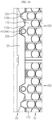
- the battery cell 111 may be provided in plural along a longitudinal direction of the unit module 110 (a direction parallel to the X-axis in FIG. 6 ) and provided in plural along a width direction of the unit module 110 (a direction parallel to the Y-axis in FIG. 6 ).
- the plurality of battery cells 111 are arranged to stand upright on the lower housing 112.
- Each of the plurality of battery cells 111 includes a positive electrode terminal 111a and a negative electrode terminal 111b exposed to the outside through an upper surface of the upper housing 113.
- a can accommodating an electrode assembly may function as the negative electrode terminal 111b.
- the plurality of battery cells 111 disposed along the longitudinal direction of the unit module 110 are connected in parallel to each other to form one cell group C.
- a plurality of cell groups C arranged along the width direction of the unit module 110 are connected in series with each other.
- two cell groups C adjacent to each other among the plurality of cell groups C will be distinguishably referred as a first cell group and a second cell group.
- such a parallel/serial connection is implemented using a plurality of parallel bus bars 114 and connecting wires W.
- the parallel bus bars 114 are disposed at both sides of each cell group C.
- the positive electrode terminals 111a of the battery cells 111 forming the first cell group C are connected to the parallel bus bar 114 located at one side of the first cell group C by wire bonding.
- the negative electrode terminals 111b of the battery cells 111 forming the first cell group C are connected to the parallel bus bar 114 located at the other side of the first cell group C by wire bonding. Accordingly, the plurality of battery cells 111 forming the first cell group C are connected in parallel with each other.
- the positive electrode terminals 111a of the plurality of battery cells 111 forming the second cell group C adjacent to the first cell group C are connected to the parallel bus bar 114 located at one side of the second cell group, namely the parallel bus bar 114 located at the other side of the first cell group C, by wire bonding.
- the negative electrode terminals 111b of the plurality of battery cells 111 forming the second cell group C are connected to the parallel bus bar 114 located at the other side of the second cell group C by wire bonding. Accordingly, the plurality of battery cells 111 forming the second cell group C are connected in parallel with each other, and the first cell group C and the second cell group C are connected in series with each other.
- the lower housing 112 supports the plurality of battery cells 111, and may include a fastening protruding portion 112a, a fixing protruding portion 112b, a first fastening accommodation portion 112c, and a first fixing accommodation portion 112d.
- At least one fastening protruding portion 112a is provided at one side of the lower housing 112 in a longitudinal direction (parallel to the X-axis in FIG. 6 ), and protrudes outward from the lower housing 112.
- the fastening protruding portion 112a has a bolting hole H1 into which a fastening bolt 4 (see FIG. 1 ) may be inserted along a height direction of the unit module 110 (a direction parallel to the Z-axis in FIG. 6 ).
- At least one fixing protruding portion 112b is provided at one longitudinal side of the lower housing 112 and protrudes outward from the lower housing 112.
- the fixing protruding portion 112b has a fixing protrusion f protruding in an upward direction (a direction parallel to the Z-axis in FIG. 6 ).
- the first fastening accommodation portion 112c is provided at the other longitudinal side of the lower housing 112, and has a shape corresponding to the fastening protruding portion 112a at a location corresponding thereto. Therefore, when the plurality of unit modules 110 are fastened along the longitudinal direction to form the sub module 100, the fastening protruding portion 112a of one unit module 110 is inserted into the first fastening accommodation portion 112c of another adjacent unit module 110.
- the upper housing 113 has a bolting hole H2 formed at a location corresponding to the first fastening accommodation portion 112c.
- the bolting hole H1 provided to the lower housing 112 and the bolting hole H2 provided to the upper housing 113 are placed at the same location so that one fastening bolt 4 (see FIG. 1 ) may pass therethrough.
- the first fixing accommodation portion 112d is provided at the other longitudinal side of the lower housing 112 and has a shape corresponding to the fixing protruding portion 112b at a location corresponding thereto. Therefore, when the plurality of unit modules 110 are fastened along the longitudinal direction to form the sub module 100, the fixing protruding portion 112b of one unit module 110 is inserted into the first fixing accommodation portion 112d of another adjacent unit module 110.
- the upper housing 113 has a protrusion accommodating groove G formed at a location corresponding to the first fixing accommodation portion 112d. Accordingly, when the pair of unit modules 110 are coupled, the fixing protrusion f provided to the lower housing 112 is inserted into the protrusion accommodating groove G provided to the upper housing 113. By doing so, the pair of unit modules 110 may be fixed not to move in the horizontal direction (a direction parallel to the X-Y plane in FIG. 6 ).
- the upper housing 113 provides a space for accommodating the plurality of battery cells 111 and has at least one bolting hole H2 and a plurality of cell exposing portions 113a formed at the upper surface thereof.
- the bolting hole H2 is formed at a location corresponding to the first fastening accommodation portion 112c of the lower housing 112 to provide a space into which the fastening bolt 4 (see FIG. 1 ) may be inserted.
- the cell exposing portion 113a has a shape extending along a longitudinal direction of the upper housing 113 (a direction parallel to the X-axis in FIG. 6 ), and is provided at a location corresponding to the cell group C in the same number as the number of cell groups C.
- the cell exposing portion 113a includes a plurality of slits S so that the positive electrode terminal 111a and the negative electrode terminal 111b of the battery cell 111 may be exposed to the outside through the upper surface of the upper housing 113.
- the positive electrode terminal 111a and the negative electrode terminal 111b exposed through the slits S are connected to the parallel bus bar 114 by wire bonding to make an electric connection where serial connections and parallel connections are mixed.
- the parallel bus bar 114 has a shape extending in a direction parallel to the cell exposing portion 113a, and is placed on the upper surface of the upper housing 113.
- the parallel bus bar 114 is disposed at both sides of each of the plurality of cell exposing portions 113a.
- the parallel bus bar 114 disposed at one end of the unit module 110 in a width direction (a direction parallel to the Y-axis in FIG. 6 ) and the parallel bus bar 114 disposed at the other end thereof have different polarities. This is to allow the plurality of sub modules 100 to be connected to each other in series along the width direction of the unit module 110.
- a pair of parallel bus bars 114 provided at the outermost sides of the sub modules 100 adjacent to each other contact each other or are connected by wire bonding, so that the adjacent sub modules 100 may be connected in series.
- the rear block 200 is a component applied for mechanical fastening of the plurality of sub modules 100 and includes a plurality of rear fastening portions 210 and a plurality of rear fixing portions 220.
- the rear fastening portion 210 has a shape corresponding to the first fastening accommodation portion 112c of the lower housing 112 at a location corresponding thereto.
- the rear fastening portion 210 has a bolting hole H3 formed in a size corresponding to the bolting hole H2 of the upper housing 113 at a location corresponding thereto.
- the rear fixing portion 220 has a shape corresponding to the first fixing accommodation portion 112d of the lower housing 112 at a location corresponding thereto. Although not shown in the figures, the rear fixing portion 220 may have a fixing protrusion formed in a size corresponding to the protrusion accommodating groove G (see FIG. 7 ) of the upper housing 113 at a location corresponding thereto.
- the BMS assembly 20 includes a plurality of battery management systems (BMSs) 21 and a BMS frame 22 for surrounding and fixing the plurality of BMS 21 at once.
- the BMS assembly 20 is coupled to one side of the battery module assembly 10 (see FIG. 5 ) in a longitudinal direction (a direction parallel to the X-axis in FIG. 5 ). That is, the BMS assembly 20 is provided in the same number as the number of sub packs 1.
- the BMS 21 is provided in plural, and the BMSs 21 are connected to the sub modules 100 in one-to-one relationship through a plurality of sensing terminals T provided to an upper portion thereof. That is, the BMSs 21 are provided in the same number as the number of sub modules 100. As shown in FIG. 14 , the sensing terminals T of the BMS 21 are connected to the parallel bus bars 114 in one-to-one relationship by wire bonding using a connecting wire W. Accordingly, one BMS 21 may sense voltage and/or current of a plurality of cell groups C (refer to FIG. 7 ) and accordingly controls charging and discharging of the sub module 100. In the figures, it is exemplarily illustrated that two BMSs 21 are provided to each BMS assembly 20. In this case, the BMSs 21 will be referred to as a first BMS 21 and a second BMS 21 for convenience of explanation.
- the first BMS 21 controls charging and discharging of the first sub module 100 (see FIG. 5 ), and the second BMS 21 controls charging and discharging of the second sub module 100 (see FIG. 5 ) adjacent to the first sub module 100.
- the BMS frame 22 surrounds and fixes the plurality of BMSs 21 at once, and is coupled to one longitudinal side of the battery module assembly 10 (see FIG. 5 ).
- the BMS frame 22 has a shape extending along the width direction of the battery module assembly 10 (see FIG. 5 ) (a direction parallel to the Y-axis in FIG. 5 ), and has a length corresponding to the width of the battery module assembly 10..
- the BMS frame 22 may include a plurality of front fastening portions 22a, a plurality of second fastening accommodation portions 22b, a plurality of second fixing accommodation portions 22c, and a bus bar placing portion 22d.
- the front fastening portion 22a is provided at a location corresponding to the fastening protruding portion 112a and has a bolting hole H4.
- the bolting hole H4 formed at the front fastening portion 22a has a shape corresponding to the bolting hole H1 formed in the lower housing 112 at a location corresponding thereto. Accordingly, one fastening bolt 4 (see FIGS. 1 and 2 ) may simultaneously pass through the bolting hole H4 formed in the front fastening portion 22a and the bolting hole H1 formed in the lower housing 112, and thus the battery module assembly 10 and the BMS assembly 20 may be fastened.
- the second fastening accommodation portion 22b has a groove shape at locations corresponding to the front fastening portion 22a and the fastening protruding portion 112a.
- the second fastening accommodation portion 22b has a shape corresponding to the fastening protruding portion 112a, and accordingly the fastening protruding portion 112a may be inserted into the second fastening accommodation portion 22b so that the BMS assembly 20 and the battery module assembly 10 come into close contact with each other.
- the second fixing accommodation portion 22c has a groove shape at a location corresponding to the fixing protruding portion 112b.
- the second fixing accommodation portion 22c has a shape corresponding to the fixing protruding portion 112b, and accordingly the fixing protruding portion 112b may be inserted into the second fixing accommodation portion 22c so that the BMS assembly 20 and the battery module assembly 10 come into close contact with each other.
- the bus bar placing portion 22d has a groove shape at one longitudinal side of the BMS frame 22.
- the bus bar placing portion 22d provides a space in which the pair of sub packs 1 coupled to each other in a mirror-symmetric form and the serial bus bar 3 for connecting the pair of sub packs 1 in series may be placed.
- the pair of BMS assemblies 20 are coupled to each other in a mirror-symmetric form based on a central axis parallel to the width direction of the battery pack (a direction parallel to the Y-axis in FIG. 15 ).
- the bus bar placing portions 22d respectively provided to the pair of BMS assemblies 20 coupled to each other as above are connected to each other to provide a space in which the serial bus bar 3 may be placed.
- the serial bus bar 3 placed on the bus bar placing portion 22d connects the parallel bus bars 114 respectively provided at the outermost parts of the pair of sub packs 1 to each other, and accordingly the pair of sub packs 1 are connected to each other in series.
- the serial bus bar 3 and the parallel bus bar 114 are electrically connected by wire bonding using a connecting wire W.
- the battery pack according to an embodiment of the present disclosure not only has a structure in which the plurality of unit modules 110 may be simply fastened by bolting, but also has a structure in which the battery module assembly 10 formed by coupling the plurality of unit modules 110 and the BMS assembly 20 may also be easily fastened by bolting.
- the battery pack according to an embodiment of the present disclosure has a structure in which the fastening bolts 4 are inserted into the bolting holes H1 to H4 in a state where the pair of sub packs 1 face each other in a mirror-symmetric form, so that the pair of sub packs 1 are fastened with each other.
- the battery pack according to an embodiment of the present disclosure has a structure in which the unit modules 110 of each sub pack 1 may be fastened and the battery module assembly 10 and the BMS assembly 20 may also be fastened simultaneously by fastening the pair of sub packs 1.
- the plurality of unit modules 110 may be simply connected in series and parallel in a mixed form, and accordingly it is very easy to expand the capacity and output voltage as needed.
- a vehicle according to an embodiment of the present disclosure includes the battery pack according to an embodiment of the present disclosure as described above.
Landscapes
- Chemical & Material Sciences (AREA)
- Chemical Kinetics & Catalysis (AREA)
- Electrochemistry (AREA)
- General Chemical & Material Sciences (AREA)
- Engineering & Computer Science (AREA)
- Manufacturing & Machinery (AREA)
- Microelectronics & Electronic Packaging (AREA)
- Aviation & Aerospace Engineering (AREA)
- Connection Of Batteries Or Terminals (AREA)
- Battery Mounting, Suspending (AREA)
Description
- The present disclosure relates to a sub pack including a plurality of unit modules and a BMS assembly, and a battery pack including the same, and more specifically, to a sub pack in which a plurality of unit modules are electrically connected through connecting wires in series and parallel, and a battery pack in which a pair of sub packs are connected in series through a serial bus bar.
- A secondary battery easily applicable to various product groups and having electrical characteristics such as high energy density is universally applied to not only portable devices but also electric vehicles (EV) or hybrid vehicles (HEV) driven by an electric drive source. The secondary battery is attracting attention as a new energy source for eco-friendliness and energy efficiency because of a primary advantage that it may dramatically reduce the use of fossil fuels and a secondary advantage that it does not generate by-products from the use of energy.
- Types of secondary batteries currently widely used in the art include lithium ion batteries, lithium polymer batteries, nickel cadmium batteries, nickel hydride batteries, nickel zinc batteries, and the like. A unit secondary battery cell, namely a unit battery cell, has an operating voltage of about 2.5V to 4.5V. Therefore, if a higher output voltage is demanded, a battery pack is formed by connecting a plurality of battery cells in series. In addition, the battery pack may be formed by connecting a plurality of battery cells in parallel according to the charge/discharge capacity required for the battery pack. Accordingly, the number of battery cells included in the battery pack may be variously set according to the required output voltage or charge/discharge capacity.
- Meanwhile, when a battery pack is configured by connecting a plurality of battery cells in series/parallel, generally, a battery module including at least one battery cell is configured first, and other components are added to the at least one battery module to configure a battery pack.
- Therefore, it is necessary to minimize a loss in terms of component cost reduction and management by developing a battery pack having a structure in which a plurality of unit modules may be electrically/mechanically coupled with each other as simple as possible and the unit modules and a battery management system (BMS) may be electrically/mechanically coupled with each other as simple as possible.
-
- The present disclosure is designed to solve the problems of the related art, and therefore the present disclosure is directed to minimizing a loss in terms of component cost reduction and management by providing a sub pack having a structure in which a plurality of unit modules may be electrically/mechanically coupled with each other as simple as possible and the unit modules and a BMS may be electrically/mechanically coupled with each other as simple as possible, and a battery pack including such sub packs.
- However, the technical problem to be solved by the present disclosure is not limited to the above, and other problems not mentioned above may be clearly understood by those skilled in the art from the following description.
- In one aspect of the present disclosure, there is provided a sub pack, comprising: a battery module assembly having a plurality of unit modules; and a BMS assembly coupled to one longitudinal side of the battery module assembly, wherein the battery module assembly includes: a first sub module having a plurality of unit modules connected along a longitudinal direction thereof; and a second sub module having a plurality of unit modules and connected to the first sub module along a width direction of the unit module, wherein the BMS assembly includes: a first BMS configured to control charging and discharging of the first sub module; a second BMS configured to control charging and discharging of the second sub module; and a BMS frame fastened to one longitudinal side of the battery module assembly while surrounding peripheries of the first BMS and the second BMS, wherein the unit module includes a plurality of battery cells configured to form a plurality of cell groups; a lower housing configured to support the plurality of battery cells, the lower housing includes at least one fastening protruding portion having a bolting hole and provided to one longitudinal side of the lower housing; at least one fixing protruding portion having a fixing protrusion and provided to one longitudinal side of the lower housing; a first fastening accommodation portion provided to the other longitudinal side of the lower housing and having a shape corresponding to the fastening protruding portion at a location corresponding thereto; and a first fixing accommodation portion provided to the other longitudinal side of the lower housing and having a shape corresponding to the fixing protruding portion at a location corresponding thereto, wherein the BMS frame includes a plurality of front fastening portions provided at a location corresponding to the fastening protruding portion and having a bolting hole; a plurality of second fastening accommodation portions provided at locations corresponding to the front fastening portion and the fastening protruding portion; and a plurality of second fixing accommodation portions provided at a location corresponding to the fixing protruding portion and having a shape corresponding thereto.
- The cell group may include a plurality of battery cells disposed along a longitudinal direction of the unit module.
- The battery cells included in the same cell group may be connected in parallel through a parallel bus bar.
- The plurality of unit modules included in the first sub module may be connected in parallel by an electric connection between the parallel bus bars located on the same extension line, and the plurality of unit modules included in the second sub module may be connected in parallel by an electric connection between the parallel bus bars located on the same extension line.
- The first sub module and the second sub module may be connected to each other in series by an electric connection between parallel bus bars adjacent to each other.
- The parallel connection between the plurality of battery cells included in the same cell group, the parallel connection between the plurality of unit modules included in the same sub module and the serial connection between the plurality of sub modules adjacent to each other may be made by wire bonding.
- An upper housing may be provided, which includes a bolting hole formed at a location corresponding to the first fastening accommodation portion; and a protrusion accommodating groove formed at a location corresponding to the first fixing accommodation portion and having a shape corresponding to the fixing protrusion.
- Each of the first BMS and the second BMS may include a plurality of sensing terminals, the sensing terminals of the first BMS may be electrically connected to the parallel bus bar of the first sub module by wire bonding, and the sensing terminals of the second BMS may be electrically connected to a parallel bus bar of the second sub module by wire bonding.
- In another aspect of the present disclosure, there is also provided a battery pack in which a pair of sub packs according to an embodiment of the present disclosure are coupled to each other in a mirror-symmetric form based on a central axis parallel to a longitudinal direction of the sub pack.
- The battery pack may further comprise a serial bus bar placed on the BMS frame to connect the pair of sub packs to each other in series.
- In another aspect of the present disclosure, there is also provided a vehicle, comprising the battery pack according to an embodiment of the present disclosure.
- According to the present disclosure, a plurality of unit modules of a battery pack are electrically/mechanically coupled with each other as simple as possible and the unit modules and a BMS are electrically/mechanically coupled with each other as simple as possible, and a battery pack including such sub packs, thereby minimizing a loss in terms of component cost reduction and management.
- The accompanying drawings illustrate a preferred embodiment of the present disclosure and together with the foregoing disclosure, serve to provide further understanding of the technical features of the present disclosure, and thus, the present disclosure is not construed as being limited to the drawing.
-
FIG. 1 is a perspective view showing a battery pack according to an embodiment of the present disclosure. -
FIG. 2 is a partial perspective view showing a front surface of the battery pack depicted inFIG. 1 . -
FIG. 3 is a perspective view showing a sub pack according to an embodiment of the present disclosure. -
FIG. 4 is a perspective view showing a lower surface of the sub pack depicted inFIG. 3 . -
FIG. 5 is a perspective view showing a battery module assembly applied to the sub pack according to an embodiment of the present disclosure. -
FIG. 6 is a perspective view showing a unit module applied to the battery module assembly depicted inFIG. 5 . -
FIG. 7 is a diagram showing a lower surface of the unit module depicted inFIG. 6 . -
FIG. 8 is a partially enlarged view showing a coupling relationship between a pair of unit modules to configure a sub module applied to the battery module assembly depicted inFIG. 5 . -
FIG. 9 is a partial perspective view showing an upper surface of the unit module depicted inFIG. 6 . -
FIG. 10 is a diagram showing an electric connection between the unit modules of the battery module assembly depicted inFIG. 5 . - FIG. 117 is a diagram showing a rear block applied to the battery module assembly depicted in
FIG. 5 . -
FIGS. 12 and 13 are perspective views showing a BMS assembly of the sub pack depicted inFIG. 3 . -
FIG. 14 is a diagram showing an electric coupling between the BMS assembly depicted inFIGS. 12 and 13 and the battery module assembly depicted inFIG. 5 . -
FIG. 15 is a diagram showing an electric connection between a pair of sub packs according to an embodiment of the present disclosure. -
FIG. 16 is a diagram showing a coupling structure between the BMS assembly and the battery module assembly of the sub pack an embodiment of the present disclosure. - Hereinafter, preferred embodiments of the present disclosure will be described in detail with reference to the accompanying drawings. Prior to the description, it should be understood that the terms used in the specification and the appended claims should not be construed as limited to general and dictionary meanings, but interpreted based on the meanings and concepts corresponding to technical aspects of the present disclosure on the basis of the principle that the inventor is allowed to define terms appropriately for the best explanation. Therefore, the description proposed herein is just a preferable example for the purpose of illustrations only, not intended to limit the scope of the disclosure, so it should be understood that other modifications could be made thereto without departing from the scope of the disclosure.
- Hereinafter, a schematic structure of a battery pack according to an embodiment of the present disclosure will be described with reference to
FIGS. 1 to 5 . - Referring to
FIGS. 1 to 5 , the battery pack according to an embodiment of the present disclosure includes a pair ofsub packs 1, aheat sink 2, aserial bus bar 3, and a plurality offastening bolts 4. - The pair of
sub packs 1 are coupled to each other in a mirror-symmetric form based on a central axis parallel to a width direction (Y-axis direction) of the battery pack with theheat sink 2 being interposed therebetween. In other words, the pair ofsub packs 1 are coupled in a state where bottom surfaces thereof face each other. Hereinafter, when necessary for convenience of description, thesub pack 1 positioned at an upper portion will be referred to as a first sub pack, and thesub pack 1 positioned at a lower portion will be referred to as a second sub pack. The detailed structure of thesub pack 1 will be described later in detail with reference toFIG. 3 . - The
heat sink 2 is a component applied for cooling the battery pack, and is interposed between the pair ofsub packs 1 so that both sides thereof contact bottom surfaces of the pair ofsub packs 1, respectively. - The
serial bus bar 3 connects the pair ofsub packs 1, which are coupled to each other in a mirror-symmetric form, in series. That is, aparallel bus bar 114 located at an outermost part of one side of thefirst sub pack 1 in a width direction (a direction parallel to the Y-axis) and aparallel bus bar 114 located at an outermost part of one side of thesecond sub pack 1 in a width direction (a direction parallel to the Y-axis) have different polarities, and theserial bus bar 3 connects the pair ofparallel bus bars 114 so that the pair ofsub packs 1 are connected in series. - The
fastening bolts 4 may be used for fastening the pair ofsub packs 1 to each other. In addition, unlike this, thefastening bolts 4 may be used forfastening unit modules 110 to each other and fastening abattery module assembly 10 and aBMS assembly 20 to each other, and thus the pair ofsub packs 1 completely fabricated as above may be coupled by an adhesive layer interposed between thefirst sub pack 1 and theheat sink 2 and between thesecond sub pack 1 and theheat sink 2. In addition, it is also possible to apply both fastening by bolting and coupling by interposing an adhesive layer in order to maximize the coupling force. - Next, a schematic structure of the
sub pack 1 according to an embodiment of the present disclosure will be described with reference toFIGS. 3 to 5 . - Referring to
FIGS. 3 to 5 , thesub pack 1 according to an embodiment of the present disclosure includes abattery module assembly 10 and aBMS assembly 20. - The
battery module assembly 10 includes a plurality ofsub modules 100, arear block 200 and aside beam 300. - The plurality of
sub modules 100 are connected to each other in series, and eachsub module 100 includes a plurality ofunit modules 110 connected to each other in parallel. In the figures, it is illustrated that onesub module 100 includes twounit modules 110 coupled to each other and onebattery module assembly 10 includes twosub modules 100 coupled to each other, but the present disclosure is not limited thereto. That is, onesub module 100 may include three ormore unit modules 110 coupled to each other, and onebattery module assembly 10 may include three ormore sub modules 100 coupled to each other. Meanwhile, for convenience of explanation, the pair ofsub modules 100 shown inFIG. 5 will be distinguishably referred to as afirst sub module 100 and asecond sub module 100. - Hereinafter, a specific structure of the
unit module 110 will be described with reference toFIGS. 6 to 9 . - Referring to
FIGS. 6 to 9 , theunit module 110 includes a plurality ofbattery cells 111, alower housing 112, anupper housing 113, and a plurality of parallel bus bars 114. - As the
battery cell 111, a cylindrical battery cell may be applied, for example. Thebattery cell 111 may be provided in plural along a longitudinal direction of the unit module 110 (a direction parallel to the X-axis inFIG. 6 ) and provided in plural along a width direction of the unit module 110 (a direction parallel to the Y-axis inFIG. 6 ). The plurality ofbattery cells 111 are arranged to stand upright on thelower housing 112. Each of the plurality ofbattery cells 111 includes apositive electrode terminal 111a and anegative electrode terminal 111b exposed to the outside through an upper surface of theupper housing 113. When thebattery cell 111 is a cylindrical battery cell, a can accommodating an electrode assembly may function as thenegative electrode terminal 111b. - The plurality of
battery cells 111 disposed along the longitudinal direction of theunit module 110 are connected in parallel to each other to form one cell group C. In addition, a plurality of cell groups C arranged along the width direction of theunit module 110 are connected in series with each other. Hereinafter, if necessary for convenience of description, two cell groups C adjacent to each other among the plurality of cell groups C will be distinguishably referred as a first cell group and a second cell group. - Referring to
FIG. 9 , such a parallel/serial connection is implemented using a plurality ofparallel bus bars 114 and connecting wires W. Theparallel bus bars 114 are disposed at both sides of each cell group C. Thepositive electrode terminals 111a of thebattery cells 111 forming the first cell group C are connected to theparallel bus bar 114 located at one side of the first cell group C by wire bonding. Thenegative electrode terminals 111b of thebattery cells 111 forming the first cell group C are connected to theparallel bus bar 114 located at the other side of the first cell group C by wire bonding. Accordingly, the plurality ofbattery cells 111 forming the first cell group C are connected in parallel with each other. - In addition, the
positive electrode terminals 111a of the plurality ofbattery cells 111 forming the second cell group C adjacent to the first cell group C are connected to theparallel bus bar 114 located at one side of the second cell group, namely theparallel bus bar 114 located at the other side of the first cell group C, by wire bonding. Thenegative electrode terminals 111b of the plurality ofbattery cells 111 forming the second cell group C are connected to theparallel bus bar 114 located at the other side of the second cell group C by wire bonding. Accordingly, the plurality ofbattery cells 111 forming the second cell group C are connected in parallel with each other, and the first cell group C and the second cell group C are connected in series with each other. - Referring to
FIGS. 6 to 9 , thelower housing 112 supports the plurality ofbattery cells 111, and may include afastening protruding portion 112a, afixing protruding portion 112b, a firstfastening accommodation portion 112c, and a firstfixing accommodation portion 112d. - At least one
fastening protruding portion 112a is provided at one side of thelower housing 112 in a longitudinal direction (parallel to the X-axis inFIG. 6 ), and protrudes outward from thelower housing 112. Thefastening protruding portion 112a has a bolting hole H1 into which a fastening bolt 4 (seeFIG. 1 ) may be inserted along a height direction of the unit module 110 (a direction parallel to the Z-axis inFIG. 6 ). At least onefixing protruding portion 112b is provided at one longitudinal side of thelower housing 112 and protrudes outward from thelower housing 112. The fixingprotruding portion 112b has a fixing protrusion f protruding in an upward direction (a direction parallel to the Z-axis inFIG. 6 ). - The first
fastening accommodation portion 112c is provided at the other longitudinal side of thelower housing 112, and has a shape corresponding to thefastening protruding portion 112a at a location corresponding thereto. Therefore, when the plurality ofunit modules 110 are fastened along the longitudinal direction to form thesub module 100, thefastening protruding portion 112a of oneunit module 110 is inserted into the firstfastening accommodation portion 112c of anotheradjacent unit module 110. In addition, theupper housing 113 has a bolting hole H2 formed at a location corresponding to the firstfastening accommodation portion 112c. Accordingly, when the pair ofunit modules 110 are coupled, the bolting hole H1 provided to thelower housing 112 and the bolting hole H2 provided to theupper housing 113 are placed at the same location so that one fastening bolt 4 (seeFIG. 1 ) may pass therethrough. - The first
fixing accommodation portion 112d is provided at the other longitudinal side of thelower housing 112 and has a shape corresponding to thefixing protruding portion 112b at a location corresponding thereto. Therefore, when the plurality ofunit modules 110 are fastened along the longitudinal direction to form thesub module 100, thefixing protruding portion 112b of oneunit module 110 is inserted into the firstfixing accommodation portion 112d of anotheradjacent unit module 110. In addition, theupper housing 113 has a protrusion accommodating groove G formed at a location corresponding to the firstfixing accommodation portion 112d. Accordingly, when the pair ofunit modules 110 are coupled, the fixing protrusion f provided to thelower housing 112 is inserted into the protrusion accommodating groove G provided to theupper housing 113. By doing so, the pair ofunit modules 110 may be fixed not to move in the horizontal direction (a direction parallel to the X-Y plane inFIG. 6 ). - The
upper housing 113 provides a space for accommodating the plurality ofbattery cells 111 and has at least one bolting hole H2 and a plurality ofcell exposing portions 113a formed at the upper surface thereof. - As mentioned above, the bolting hole H2 is formed at a location corresponding to the first
fastening accommodation portion 112c of thelower housing 112 to provide a space into which the fastening bolt 4 (seeFIG. 1 ) may be inserted. - The
cell exposing portion 113a has a shape extending along a longitudinal direction of the upper housing 113 (a direction parallel to the X-axis inFIG. 6 ), and is provided at a location corresponding to the cell group C in the same number as the number of cell groups C. Thecell exposing portion 113a includes a plurality of slits S so that thepositive electrode terminal 111a and thenegative electrode terminal 111b of thebattery cell 111 may be exposed to the outside through the upper surface of theupper housing 113. - In the plurality of the
battery cells 111 provided in oneunit module 110, thepositive electrode terminal 111a and thenegative electrode terminal 111b exposed through the slits S are connected to theparallel bus bar 114 by wire bonding to make an electric connection where serial connections and parallel connections are mixed. - The
parallel bus bar 114 has a shape extending in a direction parallel to thecell exposing portion 113a, and is placed on the upper surface of theupper housing 113. Theparallel bus bar 114 is disposed at both sides of each of the plurality ofcell exposing portions 113a. Among the plurality ofparallel bus bars 114, theparallel bus bar 114 disposed at one end of theunit module 110 in a width direction (a direction parallel to the Y-axis inFIG. 6 ) and theparallel bus bar 114 disposed at the other end thereof have different polarities. This is to allow the plurality ofsub modules 100 to be connected to each other in series along the width direction of theunit module 110. Referring toFIG. 10 , a pair ofparallel bus bars 114 provided at the outermost sides of thesub modules 100 adjacent to each other contact each other or are connected by wire bonding, so that theadjacent sub modules 100 may be connected in series. - Referring to
FIG. 11 , therear block 200 is a component applied for mechanical fastening of the plurality ofsub modules 100 and includes a plurality ofrear fastening portions 210 and a plurality of rear fixingportions 220. - The
rear fastening portion 210 has a shape corresponding to the firstfastening accommodation portion 112c of thelower housing 112 at a location corresponding thereto. Therear fastening portion 210 has a bolting hole H3 formed in a size corresponding to the bolting hole H2 of theupper housing 113 at a location corresponding thereto. - The
rear fixing portion 220 has a shape corresponding to the firstfixing accommodation portion 112d of thelower housing 112 at a location corresponding thereto. Although not shown in the figures, therear fixing portion 220 may have a fixing protrusion formed in a size corresponding to the protrusion accommodating groove G (seeFIG. 7 ) of theupper housing 113 at a location corresponding thereto. - Next, the
BMS assembly 20 will be described in detail with reference toFIGS. 12 to 16 . - Referring to
FIGS. 12 to 16 , theBMS assembly 20 includes a plurality of battery management systems (BMSs) 21 and aBMS frame 22 for surrounding and fixing the plurality ofBMS 21 at once. TheBMS assembly 20 is coupled to one side of the battery module assembly 10 (seeFIG. 5 ) in a longitudinal direction (a direction parallel to the X-axis inFIG. 5 ). That is, theBMS assembly 20 is provided in the same number as the number of sub packs 1. - The
BMS 21 is provided in plural, and theBMSs 21 are connected to thesub modules 100 in one-to-one relationship through a plurality of sensing terminals T provided to an upper portion thereof. That is, theBMSs 21 are provided in the same number as the number ofsub modules 100. As shown inFIG. 14 , the sensing terminals T of theBMS 21 are connected to theparallel bus bars 114 in one-to-one relationship by wire bonding using a connecting wire W. Accordingly, oneBMS 21 may sense voltage and/or current of a plurality of cell groups C (refer toFIG. 7 ) and accordingly controls charging and discharging of thesub module 100. In the figures, it is exemplarily illustrated that twoBMSs 21 are provided to eachBMS assembly 20. In this case, theBMSs 21 will be referred to as afirst BMS 21 and asecond BMS 21 for convenience of explanation. - The
first BMS 21 controls charging and discharging of the first sub module 100 (seeFIG. 5 ), and thesecond BMS 21 controls charging and discharging of the second sub module 100 (seeFIG. 5 ) adjacent to thefirst sub module 100. - The
BMS frame 22 surrounds and fixes the plurality ofBMSs 21 at once, and is coupled to one longitudinal side of the battery module assembly 10 (seeFIG. 5 ). TheBMS frame 22 has a shape extending along the width direction of the battery module assembly 10 (seeFIG. 5 ) (a direction parallel to the Y-axis inFIG. 5 ), and has a length corresponding to the width of thebattery module assembly 10.. - The
BMS frame 22 may include a plurality offront fastening portions 22a, a plurality of secondfastening accommodation portions 22b, a plurality of secondfixing accommodation portions 22c, and a busbar placing portion 22d. - The
front fastening portion 22a is provided at a location corresponding to thefastening protruding portion 112a and has a bolting hole H4. The bolting hole H4 formed at thefront fastening portion 22a has a shape corresponding to the bolting hole H1 formed in thelower housing 112 at a location corresponding thereto. Accordingly, one fastening bolt 4 (seeFIGS. 1 and2 ) may simultaneously pass through the bolting hole H4 formed in thefront fastening portion 22a and the bolting hole H1 formed in thelower housing 112, and thus thebattery module assembly 10 and theBMS assembly 20 may be fastened. - The second
fastening accommodation portion 22b has a groove shape at locations corresponding to thefront fastening portion 22a and thefastening protruding portion 112a. The secondfastening accommodation portion 22b has a shape corresponding to thefastening protruding portion 112a, and accordingly thefastening protruding portion 112a may be inserted into the secondfastening accommodation portion 22b so that theBMS assembly 20 and thebattery module assembly 10 come into close contact with each other. - The second
fixing accommodation portion 22c has a groove shape at a location corresponding to thefixing protruding portion 112b. The secondfixing accommodation portion 22c has a shape corresponding to thefixing protruding portion 112b, and accordingly thefixing protruding portion 112b may be inserted into the secondfixing accommodation portion 22c so that theBMS assembly 20 and thebattery module assembly 10 come into close contact with each other. - The bus
bar placing portion 22d has a groove shape at one longitudinal side of theBMS frame 22. The busbar placing portion 22d provides a space in which the pair of sub packs 1 coupled to each other in a mirror-symmetric form and theserial bus bar 3 for connecting the pair of sub packs 1 in series may be placed. As shown inFIG. 15 , the pair ofBMS assemblies 20 are coupled to each other in a mirror-symmetric form based on a central axis parallel to the width direction of the battery pack (a direction parallel to the Y-axis inFIG. 15 ). The busbar placing portions 22d respectively provided to the pair ofBMS assemblies 20 coupled to each other as above are connected to each other to provide a space in which theserial bus bar 3 may be placed. - As described above, the
serial bus bar 3 placed on the busbar placing portion 22d connects theparallel bus bars 114 respectively provided at the outermost parts of the pair ofsub packs 1 to each other, and accordingly the pair of sub packs 1 are connected to each other in series. Theserial bus bar 3 and theparallel bus bar 114 are electrically connected by wire bonding using a connecting wire W. - As described above, the battery pack according to an embodiment of the present disclosure not only has a structure in which the plurality of
unit modules 110 may be simply fastened by bolting, but also has a structure in which thebattery module assembly 10 formed by coupling the plurality ofunit modules 110 and theBMS assembly 20 may also be easily fastened by bolting. - That is, as shown in
FIGS. 1 and2 , the battery pack according to an embodiment of the present disclosure has a structure in which thefastening bolts 4 are inserted into the bolting holes H1 to H4 in a state where the pair of sub packs 1 face each other in a mirror-symmetric form, so that the pair of sub packs 1 are fastened with each other. In addition, the battery pack according to an embodiment of the present disclosure has a structure in which theunit modules 110 of eachsub pack 1 may be fastened and thebattery module assembly 10 and theBMS assembly 20 may also be fastened simultaneously by fastening the pair of sub packs 1. - In addition, if the battery pack according to an embodiment of the present disclosure is used, by using the
parallel bus bar 114 and theserial bus bar 3 and applying wire bonding to electrically connect components, the plurality ofunit modules 110 may be simply connected in series and parallel in a mixed form, and accordingly it is very easy to expand the capacity and output voltage as needed. - Meanwhile, a vehicle according to an embodiment of the present disclosure includes the battery pack according to an embodiment of the present disclosure as described above.
- The present disclosure has been described in detail. However, it should be understood that the detailed description and specific examples, while indicating preferred embodiments of the disclosure, are given by way of illustration only, since various changes and modifications within the scope of the appended claims will become apparent to those skilled in the art from this detailed description.
Claims (11)
- A sub pack (1), comprising:a battery module assembly (10) having a plurality of unit modules (110); anda BMS assembly (20) coupled to one longitudinal side of the battery module assembly (10),wherein the battery module assembly (10) includes:a first sub module (100) having a plurality of unit modules (110) connected along a longitudinal direction thereof; anda second sub module (100) having a plurality of unit modules (110) and connected to the first sub module (100) along a width direction of the unit module (110),wherein the BMS assembly (20) includes:a first BMS (21) configured to control charging and discharging of the first sub module (100);a second BMS (21) configured to control charging and discharging of the second sub module (100); anda BMS frame (22) fastened to one longitudinal side of the battery module assembly (10) while surrounding peripheries of the first BMS (21) and the second BMS (21),characterized in that the unit module (110) includes:a plurality of battery cells (111) configured to form a plurality of cell groups (C);a lower housing (112) configured to support the plurality of battery cells (111),wherein the lower housing (112) includes:at least one fastening protruding portion (112a) having a bolting hole (H1) and provided to one longitudinal side of the lower housing (112);at least one fixing protruding portion (112b) having a fixing protrusion (f) and provided to one longitudinal side of the lower housing (112);a first fastening accommodation portion (112c) provided to the other longitudinal side of the lower housing (112) and having a shape corresponding to the fastening protruding portion (112a) at a location corresponding thereto; anda first fixing accommodation portion (112d) provided to the other longitudinal side of the lower housing (112) and having a shape corresponding to the fixing protruding portion (112b) at a location corresponding thereto,wherein the BMS frame (22) includes:a plurality of front fastening portions (22a) provided at a location corresponding to the fastening protruding portion (112a) and having a bolting hole (H4);a plurality of second fastening accommodation portions (22b) provided at locations corresponding to the front fastening portion (22a) and the fastening protruding portion (112a); anda plurality of second fixing accommodation portions (22c) provided at a location corresponding to the fixing protruding portion (112b) and having a shape corresponding thereto.
- The sub pack (1) according to claim 1,
wherein the cell group (C) includes a plurality of battery cells (111) disposed along a longitudinal direction of the unit module (110). - The sub pack (1) according to claim 2,
wherein the battery cells (111) included in the same cell group (C) are connected in parallel through a parallel bus bar (114). - The sub pack (1) according to claim 3,
wherein the plurality of unit modules (110) included in the first sub module (100) are connected in parallel by an electric connection between the parallel bus bars (114) located on the same extension line, and the plurality of unit modules (110) included in the second sub module (100) are connected in parallel by an electric connection between the parallel bus bars (114) located on the same extension line. - The sub pack (1) according to claim 4,
wherein the first sub module (100) and the second sub module (100) are connected to each other in series by an electric connection between parallel bus bars (114) adjacent to each other. - The sub pack (1) according to claim 5,
wherein the parallel connection between the plurality of battery cells (111) included in the same cell group (C), the parallel connection between the plurality of unit modules (110) included in the same sub module (100) and the serial connection between the plurality of sub modules (100) adjacent to each other are made by wire bonding. - The sub pack (1) according to claim 1,
wherein an upper housing (113) is provided, which includes:a bolting hole (H2) formed at a location corresponding to the first fastening accommodation portion (112c); anda protrusion accommodating groove (G) formed at a location corresponding to the first fixing accommodation portion (112d) and having a shape corresponding to the fixing protrusion (f). - The sub pack (1) according to claim 1,wherein each of the first BMS (21) and the second BMS (21) includes a plurality of sensing terminals (T),the sensing terminals (T) of the first BMS (21) are electrically connected to the parallel bus bar (114) of the first sub module (100) by wire bonding, andthe sensing terminals (T) of the second BMS (21) are electrically connected to a parallel bus bar (114) of the second sub module (100) by wire bonding.
- A battery pack in which a pair of sub packs (1) according to claim 1 are coupled to each other in a mirror-symmetric form based on a central axis parallel to a longitudinal direction of the sub pack (1).
- The battery pack according to claim 9, further comprising:
A serial bus bar (3) placed on the BMS frame (22) to connect the pair of sub packs (1) to each other in series. - A vehicle, comprising the battery pack according to claim 9.
Applications Claiming Priority (2)
| Application Number | Priority Date | Filing Date | Title |
|---|---|---|---|
| KR1020190169899A KR102812890B1 (en) | 2019-12-18 | 2019-12-18 | Subpack comprising a plurality of unit modules and BMS assembly, and a battery pack comprising the same |
| PCT/KR2020/008813 WO2021125476A1 (en) | 2019-12-18 | 2020-07-06 | Sub pack comprising multiple unit modules and bms assembly, and battery pack comprising same |
Publications (3)
| Publication Number | Publication Date |
|---|---|
| EP4037059A1 EP4037059A1 (en) | 2022-08-03 |
| EP4037059A4 EP4037059A4 (en) | 2023-11-01 |
| EP4037059B1 true EP4037059B1 (en) | 2025-04-30 |
Family
ID=76383175
Family Applications (1)
| Application Number | Title | Priority Date | Filing Date |
|---|---|---|---|
| EP20901113.9A Active EP4037059B1 (en) | 2019-12-18 | 2020-07-06 | Sub pack comprising multiple unit modules and bms assembly, and battery pack comprising same |
Country Status (8)
| Country | Link |
|---|---|
| US (1) | US20220399578A1 (en) |
| EP (1) | EP4037059B1 (en) |
| JP (1) | JP7325601B2 (en) |
| KR (1) | KR102812890B1 (en) |
| CN (2) | CN213752926U (en) |
| ES (1) | ES3029750T3 (en) |
| PL (1) | PL4037059T3 (en) |
| WO (1) | WO2021125476A1 (en) |
Families Citing this family (6)
| Publication number | Priority date | Publication date | Assignee | Title |
|---|---|---|---|---|
| KR102812890B1 (en) * | 2019-12-18 | 2025-05-23 | 주식회사 엘지에너지솔루션 | Subpack comprising a plurality of unit modules and BMS assembly, and a battery pack comprising the same |
| JP2024526095A (en) * | 2021-06-24 | 2024-07-17 | エルジー エナジー ソリューション リミテッド | Cell module assembly and battery pack including same |
| KR20230015051A (en) * | 2021-07-22 | 2023-01-31 | 에스케이온 주식회사 | Battery module and Battery pack having the same |
| EP4310994A4 (en) * | 2022-01-24 | 2025-04-09 | Lg Energy Solution Ltd | BATTERY MODULE WITH IMPROVED IMPACT RESISTANCE AND SAFETY AND BATTERY PACK WITH IT |
| KR20240043561A (en) * | 2022-09-27 | 2024-04-03 | 주식회사 엘지에너지솔루션 | Battery pack with improved energy density by improving the sensing wire bonding of busbars |
| DE102023128242A1 (en) * | 2023-10-16 | 2025-04-17 | Lisa Dräxlmaier GmbH | Stackable battery module and battery system for a battery-powered vehicle |
Family Cites Families (20)
| Publication number | Priority date | Publication date | Assignee | Title |
|---|---|---|---|---|
| KR100895203B1 (en) * | 2006-05-15 | 2009-05-06 | 주식회사 엘지화학 | Medium and large battery module |
| KR100892046B1 (en) * | 2006-09-18 | 2009-04-07 | 주식회사 엘지화학 | Battery module and medium and large battery packs containing it |
| JP2008204987A (en) * | 2007-02-16 | 2008-09-04 | Matsushita Electric Ind Co Ltd | Power storage unit |
| JP2009231143A (en) * | 2008-03-24 | 2009-10-08 | Toshiba Corp | Battery device |
| WO2012153239A1 (en) * | 2011-05-06 | 2012-11-15 | Optimal Energy (Pty) Ltd | Battery module and control circuit therefor |
| EP2722909A4 (en) * | 2011-06-17 | 2014-12-31 | Shin Kobe Electric Machinery | ELECTROCHEMICAL CELL MODULE, ELECTROCHEMICAL CELL MODULE UNIT AND SUPPORT DEVICE |
| CN202308118U (en) * | 2011-11-08 | 2012-07-04 | 苏州新中能源科技有限公司 | Novel lithium ion power battery modular structure |
| KR102040063B1 (en) * | 2012-06-05 | 2019-11-06 | 에스케이이노베이션 주식회사 | Energy storage system and method |
| KR101805757B1 (en) * | 2013-08-23 | 2017-12-07 | 주식회사 엘지화학 | Battery Module Assembly Having Protruded Communication Terminals of BMS in Front thereof |
| KR101666376B1 (en) * | 2013-12-27 | 2016-10-14 | 주식회사 엘지화학 | Harness Cover |
| KR101586668B1 (en) * | 2013-12-27 | 2016-01-19 | 주식회사 엘지화학 | Battery Module Assembly Including Sub-Modules Inside |
| KR101776853B1 (en) * | 2015-06-30 | 2017-09-12 | 인지컨트롤스 주식회사 | Battery pack |
| KR102162968B1 (en) * | 2017-04-07 | 2020-10-07 | 주식회사 엘지화학 | Battery Pack with extendible battery module |
| WO2019044724A1 (en) | 2017-09-04 | 2019-03-07 | パナソニックIpマネジメント株式会社 | Battery module |
| US20190081370A1 (en) * | 2017-09-12 | 2019-03-14 | Sf Motors, Inc. | Embedded current collector for electric vehicle battery monitoring |
| KR102249509B1 (en) * | 2017-09-20 | 2021-05-06 | 주식회사 엘지화학 | Battery Module Having Guide Coupling Structure and Battery Pack Having The Same |
| US20190131672A1 (en) * | 2017-11-01 | 2019-05-02 | Lithos Energy, Inc. | High power battery modules with pcb sensing assembly |
| KR102258837B1 (en) * | 2017-11-06 | 2021-06-07 | 주식회사 엘지에너지솔루션 | Battery Pack enhanced assembling structure |
| US10243184B1 (en) * | 2018-02-03 | 2019-03-26 | Thor Trucks Inc. | Modular battery configured for wire bonding |
| KR102812890B1 (en) * | 2019-12-18 | 2025-05-23 | 주식회사 엘지에너지솔루션 | Subpack comprising a plurality of unit modules and BMS assembly, and a battery pack comprising the same |
-
2019
- 2019-12-18 KR KR1020190169899A patent/KR102812890B1/en active Active
-
2020
- 2020-07-06 JP JP2022502151A patent/JP7325601B2/en active Active
- 2020-07-06 EP EP20901113.9A patent/EP4037059B1/en active Active
- 2020-07-06 WO PCT/KR2020/008813 patent/WO2021125476A1/en active IP Right Grant
- 2020-07-06 US US17/633,858 patent/US20220399578A1/en active Pending
- 2020-07-06 ES ES20901113T patent/ES3029750T3/en active Active
- 2020-07-06 PL PL20901113.9T patent/PL4037059T3/en unknown
- 2020-12-03 CN CN202022866719.7U patent/CN213752926U/en not_active Withdrawn - After Issue
- 2020-12-03 CN CN202011396538.0A patent/CN113013540B/en active Active
Also Published As
| Publication number | Publication date |
|---|---|
| WO2021125476A1 (en) | 2021-06-24 |
| KR20210078139A (en) | 2021-06-28 |
| ES3029750T3 (en) | 2025-06-25 |
| EP4037059A4 (en) | 2023-11-01 |
| EP4037059A1 (en) | 2022-08-03 |
| US20220399578A1 (en) | 2022-12-15 |
| PL4037059T3 (en) | 2025-06-23 |
| JP2022540489A (en) | 2022-09-15 |
| CN113013540A (en) | 2021-06-22 |
| KR102812890B1 (en) | 2025-05-23 |
| CN213752926U (en) | 2021-07-20 |
| CN113013540B (en) | 2024-04-12 |
| JP7325601B2 (en) | 2023-08-14 |
Similar Documents
| Publication | Publication Date | Title |
|---|---|---|
| EP4037059B1 (en) | Sub pack comprising multiple unit modules and bms assembly, and battery pack comprising same | |
| EP4030548A1 (en) | Sub-pack including multiple unit modules and bms assembly, and battery pack comprising same | |
| US11196120B2 (en) | Battery module, and battery pack and vehicle comprising same | |
| EP2388845B1 (en) | Battery pack | |
| KR101217564B1 (en) | Voltage Sensing Assembly and Battery Module Employed with the Same | |
| EP3076456B1 (en) | Battery module and battery pack comprising same | |
| KR102250204B1 (en) | Battery module, battery pack comprising the battery module and vehicle comprising the battery pack | |
| US20210313657A1 (en) | Battery Module with ICB Assembly in Space-Saving Structure | |
| JP7453376B2 (en) | Battery packs and automobiles containing them | |
| EP3780287B1 (en) | Battery module including connector having shock absorbing structure | |
| EP3579298A1 (en) | Battery pack and holder | |
| KR20200004187A (en) | Battery module, battery pack comprising the battery module and vehicle comprising the battery pack | |
| EP4030515B1 (en) | Battery module | |
| EP3764421B1 (en) | Battery module including connector having bidirectional coupling structure | |
| KR102455471B1 (en) | Battery cell, battery module comprising the battery cell, battery rack comprising the battery module and energy storage system comprising the battery rack | |
| KR102201333B1 (en) | Battery pack having inner tention-bar | |
| KR20250086390A (en) | Battery pack, vehicle comprising the battery pack, and manufacturing method of the battery pack | |
| KR20250040390A (en) | Battery pack and vehicle including the same | |
| KR102111767B1 (en) | Battery pack and vehicle comprising the battery pack | |
| KR20240007501A (en) | Battery module, battery pack and vehicle including the same |
Legal Events
| Date | Code | Title | Description |
|---|---|---|---|
| STAA | Information on the status of an ep patent application or granted ep patent |
Free format text: STATUS: THE INTERNATIONAL PUBLICATION HAS BEEN MADE |
|
| PUAI | Public reference made under article 153(3) epc to a published international application that has entered the european phase |
Free format text: ORIGINAL CODE: 0009012 |
|
| STAA | Information on the status of an ep patent application or granted ep patent |
Free format text: STATUS: REQUEST FOR EXAMINATION WAS MADE |
|
| 17P | Request for examination filed |
Effective date: 20220426 |
|
| AK | Designated contracting states |
Kind code of ref document: A1 Designated state(s): AL AT BE BG CH CY CZ DE DK EE ES FI FR GB GR HR HU IE IS IT LI LT LU LV MC MK MT NL NO PL PT RO RS SE SI SK SM TR |
|
| DAV | Request for validation of the european patent (deleted) | ||
| DAX | Request for extension of the european patent (deleted) | ||
| A4 | Supplementary search report drawn up and despatched |
Effective date: 20230928 |
|
| RIC1 | Information provided on ipc code assigned before grant |
Ipc: H01M 50/502 20210101ALI20230922BHEP Ipc: H01M 50/213 20210101ALI20230922BHEP Ipc: H01M 10/42 20060101AFI20230922BHEP |
|
| STAA | Information on the status of an ep patent application or granted ep patent |
Free format text: STATUS: EXAMINATION IS IN PROGRESS |
|
| 17Q | First examination report despatched |
Effective date: 20240614 |
|
| 17Q | First examination report despatched |
Effective date: 20240625 |
|
| GRAP | Despatch of communication of intention to grant a patent |
Free format text: ORIGINAL CODE: EPIDOSNIGR1 |
|
| STAA | Information on the status of an ep patent application or granted ep patent |
Free format text: STATUS: GRANT OF PATENT IS INTENDED |
|
| INTG | Intention to grant announced |
Effective date: 20250116 |
|
| P01 | Opt-out of the competence of the unified patent court (upc) registered |
Free format text: CASE NUMBER: APP_6053/2025 Effective date: 20250205 |
|
| GRAS | Grant fee paid |
Free format text: ORIGINAL CODE: EPIDOSNIGR3 |
|
| GRAA | (expected) grant |
Free format text: ORIGINAL CODE: 0009210 |
|
| STAA | Information on the status of an ep patent application or granted ep patent |
Free format text: STATUS: THE PATENT HAS BEEN GRANTED |
|
| AK | Designated contracting states |
Kind code of ref document: B1 Designated state(s): AL AT BE BG CH CY CZ DE DK EE ES FI FR GB GR HR HU IE IS IT LI LT LU LV MC MK MT NL NO PL PT RO RS SE SI SK SM TR |
|
| REG | Reference to a national code |
Ref country code: CH Ref legal event code: EP Ref country code: GB Ref legal event code: FG4D |
|
| REG | Reference to a national code |
Ref country code: IE Ref legal event code: FG4D |
|
| REG | Reference to a national code |
Ref country code: DE Ref legal event code: R096 Ref document number: 602020050631 Country of ref document: DE |
|
| REG | Reference to a national code |
Ref country code: NL Ref legal event code: FP |
|
| REG | Reference to a national code |
Ref country code: SE Ref legal event code: TRGR |
|
| REG | Reference to a national code |
Ref country code: ES Ref legal event code: FG2A Ref document number: 3029750 Country of ref document: ES Kind code of ref document: T3 Effective date: 20250625 |
|
| PGFP | Annual fee paid to national office [announced via postgrant information from national office to epo] |
Ref country code: GB Payment date: 20250624 Year of fee payment: 6 |