EP4036942A1 - Coil component - Google Patents
Coil component Download PDFInfo
- Publication number
- EP4036942A1 EP4036942A1 EP22150166.1A EP22150166A EP4036942A1 EP 4036942 A1 EP4036942 A1 EP 4036942A1 EP 22150166 A EP22150166 A EP 22150166A EP 4036942 A1 EP4036942 A1 EP 4036942A1
- Authority
- EP
- European Patent Office
- Prior art keywords
- plate
- core body
- recess
- arc
- planar
- Prior art date
- Legal status (The legal status is an assumption and is not a legal conclusion. Google has not performed a legal analysis and makes no representation as to the accuracy of the status listed.)
- Granted
Links
Images






Classifications
-
- H—ELECTRICITY
- H01—ELECTRIC ELEMENTS
- H01F—MAGNETS; INDUCTANCES; TRANSFORMERS; SELECTION OF MATERIALS FOR THEIR MAGNETIC PROPERTIES
- H01F27/00—Details of transformers or inductances, in general
- H01F27/28—Coils; Windings; Conductive connections
- H01F27/29—Terminals; Tapping arrangements for signal inductances
-
- H—ELECTRICITY
- H01—ELECTRIC ELEMENTS
- H01F—MAGNETS; INDUCTANCES; TRANSFORMERS; SELECTION OF MATERIALS FOR THEIR MAGNETIC PROPERTIES
- H01F27/00—Details of transformers or inductances, in general
- H01F27/28—Coils; Windings; Conductive connections
- H01F27/29—Terminals; Tapping arrangements for signal inductances
- H01F27/292—Surface mounted devices
-
- H—ELECTRICITY
- H01—ELECTRIC ELEMENTS
- H01F—MAGNETS; INDUCTANCES; TRANSFORMERS; SELECTION OF MATERIALS FOR THEIR MAGNETIC PROPERTIES
- H01F5/00—Coils
-
- H—ELECTRICITY
- H01—ELECTRIC ELEMENTS
- H01F—MAGNETS; INDUCTANCES; TRANSFORMERS; SELECTION OF MATERIALS FOR THEIR MAGNETIC PROPERTIES
- H01F27/00—Details of transformers or inductances, in general
- H01F27/02—Casings
-
- H—ELECTRICITY
- H01—ELECTRIC ELEMENTS
- H01F—MAGNETS; INDUCTANCES; TRANSFORMERS; SELECTION OF MATERIALS FOR THEIR MAGNETIC PROPERTIES
- H01F27/00—Details of transformers or inductances, in general
- H01F27/24—Magnetic cores
- H01F27/26—Fastening parts of the core together; Fastening or mounting the core on casing or support
- H01F27/266—Fastening or mounting the core on casing or support
-
- H—ELECTRICITY
- H01—ELECTRIC ELEMENTS
- H01F—MAGNETS; INDUCTANCES; TRANSFORMERS; SELECTION OF MATERIALS FOR THEIR MAGNETIC PROPERTIES
- H01F27/00—Details of transformers or inductances, in general
- H01F27/28—Coils; Windings; Conductive connections
Definitions
- the present application relates to a coil component.
- the coil component that is described in Japanese Patent Publication Number 2007-273739 has a core molding (a core mold or a molded core), a coil, and a metal terminal.
- the core molding is formed of a magnetic substance material.
- the coil has an embedded part that is embedded into the core molding and a protruding part that protrudes from the core molding.
- the metal terminal is electrically connected to the protruding part.
- the core molding has a mounting surface, an upper surface, and a side surface. Specifically, the upper surface faces the opposite direction as the mounting surface. The side surface is orthogonal to the mounting surface and the upper surface.
- the metal terminal has a first planar part, a second planar part, and a third planar part.
- the first planar part is arranged along the side surface of the core molding.
- the second planar part is connected to an upper end of the first planar part and is arranged along the upper surface of the core molding.
- the third planar part is connected to a lower end of the first planar part and is arranged along the mounting surface of the core molding.
- a recessed part is formed in the upper surface of the core molding.
- the second planar part of the metal terminal is arranged at the recessed part.
- the coil components explained above may be subjected to a vacuum and held by a mounter that has a suction nozzle during, for example, a mounting process.
- An object of the present application is to provide a coil component that has a configuration that enables a mounter to perform a suction more stably.
- a coil component includes a core body, a coil, and a metal terminal.
- the core body is formed of a magnetic material.
- the core body has a mounting surface, an upper surface, the upper surface and the mounting surface being outwardly opposite to each other, and a first side surface joining (crossing) the mounting surface and the upper surface.
- the coil has an embedded part embedded in the core body, and a first protruding part protruding from the core body.
- the metal terminal is electrically connected to the first protruding part of the coil.
- the metal terminal has a first plate arranged along the first side surface of the core body, a second plate continuously connected to an upper end of the first plate and arranged along the upper surface of the core body, and a third plate continuously connected to a lower end of the first plate and arranged along the mounting surface of the core body. Further, a leading edge of the second plate is recessed toward the upper end of the first plate to form a first arc-shaped part.
- the upper surface of the core body has a first recess in which the second plate is arranged.
- the first recess has a second arc-shaped part at a portion facing the first arc-shaped part.
- the second arc-shaped part extends along a contour of the first arc-shaped part.
- a suction by a mounter can be performed more stably.
- a coil component 100 has a core body 10 (alternately, a core, a core molding, a core mold, or a molded core), a coil 60, and a metal terminal(s) 50.
- the core body 10 is formed of (made of or includes) a magnetic substance material (magnetic material).
- the coil 60 has an embedded part 61 that is embedded in the core body 10 (for instance, shown in Figs. 8A and 9 ) and a protruding part(s) (a first protruding part 62 and a second protruding part 63, for instance, shown in Fig. 8A ) that protrudes from the core body 10.
- the metal terminal 50 is electrically connected to the protruding part of the coil 60.
- the core body 10 has a mounting surface 11 (for instance, shown in Fig. 7 ), an upper surface 12, and a side surface(s).
- the upper surface 12 faces an opposite side to the mounting surface 11.
- the side surfaces join (cross) (or are orthogonal to) the mounting surface 11 and the upper surface 12.
- the side surfaces are a front surface 13, a rear surface 14, a left side surface 15, a right side surface 16, a front left surface 21, a rear left surface 22, a rear right surface 23, and a front right surface 24.
- the metal terminal 50 has a first planar part (first plate) 51, a second planar part (second plate) 52, and a third planar part (third plate) 53.
- first planar part 51 is arranged along the side surface of the core body 10.
- the second planar part 52 is continuously connected to an upper end (edge) of the first planar part 51 and is arranged along the upper surface 12 of the core body 10.
- the third planar part 53 is continuously connected to a lower end (edge) of the first planar part 51 and is arranged along the mounting surface 11 of the core body 10.
- the first, second, and third planar parts 51, 52, and 53 are integrally formed.
- a monolithic member configures the first, second, and third planar parts 51, 52, and 53.
- a leading edge (tip edge or forefront edge) of the second planar part 52 is a first recess-shaped part (first arc-shaped part or first arc part) 52a (for instance, shown in Fig. 8A ).
- the first recess-shaped part 52a is hollowed (recessed or depressed) toward an upper end (edge) side of the first planar part 51 and the leading edge of the first recess-shaped part 52a is formed to be in a planar shape (arc-planar shape).
- the upper edge side of the first planar part 51 is a base end side of the second planar part 52.
- a recessed part 30 is formed in the upper surface 12 of the core body 10.
- the second planar part 52 is arranged in the recessed part 30 of the upper surface 12.
- a second recess-shaped part (second arc-shaped part or second arc part) 30a (for instance, shown in Fig. 8A ) of the recessed part 30 corresponds to or is formed along the first recess-shaped part 52a.
- the second recess-shaped part 30a is formed to be in a planar shape (arc-planar shape) along the planar shape of the first recess-shaped part 52a.
- the second recess-shaped part 30a of the recessed part 30 extends along a configuration (shape) of the first recess-shaped part 52a as shown in Figs. 1 , 6 , 8A , and 10 .
- the area of a region that can be sucked (subject to a vacuum) by a suction nozzle of a mounter can be sufficiently secured and ensured on the upper surface 12.
- a suction nozzle a suction area of the suction nozzle
- the sucked region is efficiently secured on the upper surface 12 of the core body 10.
- the suction of the coil component 100 by the mounter can be performed more stably.
- the coil component 100 according to the embodiments of the present application is explained in detail below.
- the core body 10 is formed by a compression molding of powders including a magnetic substance material. During the process of the compression molding, the embedded part 61 of the coil 60 is embedded into the core body 10.
- the shape of the core body 10 is not particularly limited. However, for instance, the core body 10 has the mounting surface 11, the upper surface 12, and a plurality of side surfaces that are respectively orthogonal to the mounting surface 11 and the upper surface 12.
- the mounting surface 11 is formed to be flat except for, for instance, a pair of second recessed parts 40 described below.
- the upper surface 12 is formed to be flat except for, for instance, a pair of (first) recessed parts 30. Further, the upper surface 12 is arranged in parallel to the mounting surface 11.
- the side surfaces of the core body 10 has the front surface 13, the rear surface 14, the left side surface 15, and the right side surface 16.
- the rear surface 14 is arranged in parallel to the front surface 13 and faces the opposite side to the front surface 13.
- the left side surface 15 is orthogonal to the front surface 13 and the rear surface 14.
- the right side surface 16 is arranged in parallel to the left side surface 15 and faces the opposite side to the left side surface 15.
- the core body 10 has, for instance, the front left surface 21, the rear left surface 22, the rear right surface 23, and the front right surface 24 as the side surfaces.
- the front left surface 21 is arranged between the front surface 13 and the left side surface 15 and connects the front surface 13 with the left side surface 15.
- the rear left surface 22 is arranged between the left side surface 15 and the rear surface 14 and connects the left side surface 15 with the rear surface 14.
- the rear right surface 23 is arranged between the rear surface 14 and the right side surface 16 and connects the rear surface 14 with the right side surface 16.
- the front right surface 24 is arranged between the right side surface 16 and the front surface 13 and connects the right side surface 16 with the front surface 13.
- the front left surface 21 is, for instance, tilted relative to each of the front surface 13 and the left side surface 15 at an angle of 135 degrees.
- the rear left surface 22 is, for instance, tilted relative to each of the left side surface 15 and the rear surface 14 at an angle of 135 degrees.
- the rear right surface 23 is, for instance, tilted relative to each of the rear surface 14 and the right side surface 16 at an angle of 135 degrees.
- the front right surface 24 is, for instance, tilted relative to each of the right side surface 16 and the front surface 13 at an angle of 135 degrees.
- all of the rear left surface 22, the rear right surface 23, and the front right surface 24 have the same shapes and the same sizes (the same areas).
- the front left surface 21 is smaller than the rear left surface 22, the rear right surface 23, and the front right surface 24 as shown in Fig. 8A .
- the front left surface 21 is smaller than the rear left surface 22, the rear right surface 23, and the front right surface 24.
- Each of the front surface 13, the rear surface 14, the left side surface 15, the right side surface 16, the front left surface 21, the rear left surface 22, the rear right surface 23, and the front right surface 24 is, for instance, formed to be flat.
- a pair of left and right (first) recessed parts 30 is formed on the upper surface 12.
- a pair of left and right second recessed parts 40 is formed on the mounting surface 11.
- the coil 60 is configured by a single round wire.
- the coil 60 has the embedded part 61 that is configured by winding the (single) round wire and a pair of protruding parts (the first protruding part 62 and the second protruding part 63) that protrude toward an outside in the radial direction from the embedded part 61.
- An axis direction of the coil 60 is in the vertical direction.
- the first protruding part 62 is configured by one end of the (single) round wire.
- the second protruding part 63 is configured by the other end of the (single) round wire.
- the first protruding part 62 and the second protruding part 63 horizontally protrude from the embedded part 61.
- first protruding part 62 and the second protruding part 63 mutually protrude in the opposite directions from the embedded part 61.
- the first protruding part 62 horizontally protrudes from, for instance, the lower part of the rear left surface 22 of the core body 10.
- the second protruding part 63 horizontally protrudes from, for instance, the lower part of the front right surface 24 of the core body 10.
- the protruding direction of the first protruding part 62 protruded from the rear left surface 22 is orthogonal to the rear left surface 22.
- the protruding direction of the second protruding part 63 protruded from the front right surface 24 is orthogonal to the front right surface 24.
- the coil 60 is not limited to be configured by the single round wire according to the embodiments of the present application.
- the coil 60 may be, for instance, an edgewise coil that is configured by winding a flat wire.
- the metal terminal 50 is, for instance, configured by a folding process of a single metal plate.
- the metal terminal 50 has the first planar part (first plate) 51, the second planar part (second plate) 52, and the third planar part (third plate) 53 that are respectively formed to be a flat-shaped plate.
- the second planar part 52 is continuously connected to the upper end of the first planar part 51 and is substantially orthogonal to the first planar part 51.
- the third planar part 53 is continuously connected to the lower end of the first planar part 51 and is substantially orthogonal to the first planar part 51.
- the second planar part 52 and the third planar part 53 are located at opposite positions to each other and are substantially parallel to each other (refer to Fig. 9 ).
- the first planar part(s) 51 is, for instance, formed to be in a rectangular shape that is vertically long.
- the second planar part(s) 52 is, for instance, formed to be in a rectangular shape that is longer in a front-rear direction than in a right-left direction in the plan view.
- the leading edge(s) of the second planar part(s) 52 is the first recess-shaped part(s) (first arc-shaped part or first arc part) 52a as explained above.
- a lateral width dimension (in the sight-left direction) of the second planar part(s) 52 is, for instance, more than two times of a plate thickness of the metal terminal 50.
- the lateral width dimension (in the sight-left direction) of the second planar part(s) 52 is, for instance, more than three times of the plate thickness of the metal terminal 50.
- the third planar part(s) 53 is, for instance, formed to be in a rectangular shape that is longer in the front-rear direction than in the right-left direction in the plan view.
- the metal terminal 50 has a fourth planar part (fourth plate) 54 and a fifth planar part (fifth plate) 55.
- the fourth planar part 54 is continuously connected to a side edge 51a of the first planar part 51 and joins (crosses) the first planar part 51.
- the fifth planar part 55 is continuously connected to a leading edge (tip edge or forefront edge) 54a of the fourth planar part 54 and joins (crosses) the fourth planar part 54. Because the fourth planar part 54 and the fifth planar part 55 are formed by the bending (folding) process of the metal terminal 50, the side edge 51a and the leasing edge 54a are folds or ridges of the metal terminal 50.
- the fourth planar part 54 and the fifth planar part 55 are also respectively formed to be a flat-shaped plate. As shown in such as Figs. 1 - 5 , each of the fourth planar part 54 and the fifth planar part 55 is, for instance, formed to be in a rectangular shape that is vertically long.
- an angle between the first planar part 51 and the fourth planar part 54 is, for instance, set to be 135 degrees (refer to such as Fig. 8A ).
- an angle between the fourth planar part 54 and the fifth planar part 55 is, for instance, set to be 90 degrees (refer to such as Fig. 8A ).
- the first planar part 51, the fourth planar part 54, and the fifth planar part 55 are respectively vertically arranged or extend in the vertical (up and down) direction.
- the second planar part 52 and the third planar part 53 are respectively substantially horizontally arranged or substantially extend in the horizontal direction.
- a welded piece (welded strip) 56 is formed at a lower end part of the fifth planar part 55.
- the welded piece(s) 56 is welded to the protruding part(s) (the first protruding part 62 and the second protruding part 63) of the coil 60 (refer to such as Fig. 7 ).
- the coil component 100 has a pair of left and right metal terminals (first and second metal terminals) 50.
- the pair of metal terminals 50 are mutually formed to be in the same shapes and the same sizes.
- the first planar part 51 of one (the left side) of the metal terminals 50 is arranged along the left side surface 15.
- the second planar part 52 of this metal terminal 50 is arranged at or in the recessed part 30 on the left side.
- the third planar part 53 of this metal terminal 50 is arranged at or in the second recessed part 40 on the left side.
- the fourth planar part 54 of this metal terminal 50 on the left side is, for instance, arranged along the rear left surface 22.
- the fifth planar part 55 of this metal terminal 50 substantially vertically raises relative to (substantially uprises with respect to or substantially stands from) the rear left surface 22.
- the first planar part 51 of the other (the right side) of the metal terminals 50 is arranged along the right side surface 16.
- the second planar part 52 of this metal terminal 50 is arranged at or in the recessed part 30 on the right side.
- the third planar part 53 of this metal terminal 50 is arranged at or in the second recessed part 40 on the right side.
- the fourth planar part 54 of this metal terminal 50 on the right side is, for instance, arranged along the front right surface 24.
- the fifth planar part 55 of this metal terminal 50 substantially vertically raises relative to (substantially uprises with respect to or substantially stands from) the front right surface 24.
- the second recessed parts 40 at or in which the third planar parts 53 are arranged are formed on the mounting surface 11.
- the fourth planar parts 54 are arranged along the side surfaces of the core body 10.
- the fifth planar parts 55 raise relative to the side surfaces of the core body 10.
- the fifth planar parts 55 raise from the side surfaces of the core body 10, the satisfactory or excellent heat dissipation from the fifth planar parts 55 can be realized. It is preferred that the vertical dimension (length) of each of the fifth planar parts 55 is half or more of the vertical dimension (length or height) of the core body 10. It is more preferred that the vertical dimension (length) of each of the fifth planar parts 55 is two thirds or more of the vertical dimension (length or height) of the core body 10.
- the metal terminal 50 is adhered and fixed to the core body 10.
- the first planar part 51 is in surface contact with the side surface of the core body 10 and is surface-joined to the core body 10 by an adhesive.
- the welded piece 56 of the metal terminal 50 on the left side is welded to one of the protruding parts (the first protruding part 62) of the coil 60.
- the welded piece 56 of the metal terminal 50 on the right side is welded to the other of the protruding parts (the second protruding part 63) of the coil 60.
- the welded piece 56 and the first protruding part 62 of the metal terminal 50 on the left side are mutually welded at a first welding part 71 that is in a spherical shape.
- the welded piece 56 and the second protruding part 63 of the metal terminal 50 on the right side are mutually welded at a second welding part 72 that is in a spherical shape.
- the recessed part 30 on the left side of the pair of left and right recessed parts 30 is arranged at the left end of the upper surface 12.
- the recessed part 30 on the right side is arranged at the right end of the upper surface 12.
- each of the recessed parts 30 is configured with a first step 31 (a bottom surface), a first tilted (inclined) surface (wall) 32 (an upper tilted surface), a second step 35, a second tilted surface 36, and a pair of vertical surfaces (walls) 37.
- first tilted surface 32 is arranged at the peripheral edge of the recessed part 30.
- the second step 35 is arranged at a lower step as compared with the first step 31.
- the second tilted surface 36 is arranged between the first step 31 and the second step 35 and is tilted downward toward the side of the second step 35 from the side of the first step 31.
- the first step 31 occupies the most of the plane area of the recessed part 30.
- a bottom surface of the first step 31 is substantially horizontally arranged.
- the first step 31 increases in depth as it becomes far from the side surface of the core body 10.
- the left edge of the first step 31 of the recessed part 30 on the left side linearly extends in the front-rear direction.
- Each of the front and rear edges of the first step 31 of the recessed part 30 on the left side linearly extends in the right-left direction.
- the second step 35 of the recessed part 30 on the left side linearly extends in the front-rear direction along the left edge of the first step 31 of the recessed part 30 on the left side, and at the same time, is substantially horizontally arranged.
- the left edge of the second step 35 of the recessed part 30 on the left side serves as the upper edge of the left side surface 15 at a position where the recessed part 30 on the left side is formed.
- the right edge of the first step 31 of the recessed part 30 on the right side linearly extends in the front-rear direction.
- Each of the front and rear edges of the first step 31 of the recessed part 30 on the right side linearly extends in the right-left direction.
- the second step 35 of the recessed part 30 on the right side linearly extends in the front-rear direction along the right edge of the first step 31 of the recessed part 30 on the right side, and at the same time, is substantially horizontally arranged.
- the right edge of the second step 35 of the recessed part 30 on the right side serves as the upper edge of the right side surface 16 at a position where the recessed part 30 on the right side is formed.
- the second tilted surface 36 is arranged between the first step 31 and the second step 35.
- the second tilted surface 36 of the recessed part 30 on the left side extends in the front-rear direction along the left edge of the first step 31 of the recessed part 30 on the left side and is tilted downward toward the left side.
- the first tilted surface 32 of the recessed part 30 on the left side is continuously arranged along the right edge, the front edge, and the rear edge of this recessed part 30.
- the second tilted surface 36 of the recessed part 30 on the right side extends in the front-rear direction along the right edge of the first step 31 of the recessed part 30 on the right side and is tilted downward toward the right side.
- the first tilted surface 32 of the recessed part 30 on the right side is continuously arranged along the left edge, the front edge, and the rear edge of this recessed part 30.
- Each of the first tilted surfaces 32 is tilted to a direction in which the recessed part 30 becomes smaller (narrow) toward the depth direction (downward) of each of the recessed parts 30. In other words, each of the first tilted surfaces 32 is tilted downward and inward with respect to the recessed part 30.
- the first tilted surface 32 works as a draft angle when the core body 10 is pulled (taken out) from a mold after being formed by a molding process.
- the lower end of the first tilted surface 32 is positioned at the same height position as the bottom surface of the first step 31.
- the vertical surfaces 37 which are vertically arranged, are respectively arranged between both ends of the second step 35 and the second tilted surface 36 in the front-rear direction and the lower end of the first tilted surface 32.
- the planar shape of the recessed part 30 corresponds to the planar shape of the second planar part 52.
- Each of the second planar parts 52 enters into each of the recessed parts 30.
- the leading edge of the second planar part 52 of the metal terminal 50 is the first recess-shaped part 52a.
- the first recess-shaped part 52a is hollowed (recessed or depressed) toward the upper edge side of the first planar part 51 and is formed to be in the planar shape.
- a right edge (the leading edge) of the second planar part 52 of the metal terminal 50 on the left side is hollowed toward the left side.
- a left edge (the leading edge) of the second planar part 52 of the metal terminal 50 on the right side is hollowed toward the right side.
- the right edge of the second planar part 52 of the metal terminal 50 on the left side is hollowed toward the left side in a circular arc shape (in an arc shape).
- the left edge of the second planar part 52 of the metal terminal 50 on the right side is hollowed toward the right side in the circular arc shape (in the arc shape).
- both ends of the leading edge of the second planar part 52 are respectively formed to be in a projecting circular arc shape toward the outside of the second planar part 52.
- the portions that correspond to both ends of the leading edge of the second planar part 52 are respectively formed to be in the circular arc shape along both ends of the leading edge of the second planar part 52.
- the portion of the recessed parts 30 that corresponds to the first recess-shaped part 52a is the second recess-shaped part 30a that is formed to be in the planar shape along the first recess-shaped part 52a.
- planar shape of the right edge of the first step 31 of the recessed part 30 on the left side and the planar shape of the portion that is arranged along the right edge of the first step 31 of the first tilted surface 32 of the recessed part 30 on the left side are formed to be in the recessed shape that is hollowed toward the left side and is in a circular arc shape.
- planar shape of the left edge of the first step 31 of the recessed part 30 on the right side and the planar shape of the portion that is arranged along the left edge of the first step 31 of the first tilted surface 32 of the recessed part 30 on the right side are formed to be in the recessed shape that is hollowed toward the right side and is in a circular arc shape.
- the second recess-shaped part 30a of the recessed part 30 on the left side and the second recess-shaped part 30a of the recessed part 30 on the right side are mutually arranged on the same circumference in the plan view.
- these (two of) second recess-shaped parts 30a extend along the same circumference of a circle R1 (see Fig. 8A ) (are concentrically arranged) on the upper surface 12 of the core body 10 in the plan view.
- the coil 60 has the pair of protruding parts (the first protruding part 62 and the second protruding part 63).
- the coil component 100 has the pair of metal terminals 50.
- One of the pair of metal terminals 50 is electrically connected to one of the pair of protruding parts.
- the other of the pair of metal terminals 50 is electrically connected to the other of the pair of protruding parts.
- the second planar part 52 of one of the pair of metal terminals 50 is arranged at or in one of the pair of recessed parts 30.
- the second planar part 52 of the other of the pair of metal terminals 50 is arranged at or in the other of the pair of recessed parts 30.
- the second recess-shaped part 30a of one of the pair of recessed parts 30 and the second recess-shaped part 30a of the other of the pair of recessed parts 30 are mutually arranged on the same circumference in the plan view.
- these (two of) second recess-shaped parts 30a extend along the same circumference of a circle R1 (see Fig. 8A ) (are concentrically arranged) on the upper surface 12 of the core body 10 in the plan view.
- the circular region being surrounded by the second recess-shaped parts 30a of the pair of recessed parts 30 on the upper surface 12 can be excellently sucked by a suction nozzle of a mounter.
- a circle R2 corresponds to, for example, a periphery of the suction nozzle of the mounter or the sucked region.
- the second recessed part 40 on the left side of a pair of left and right second recessed parts 40 is arranged at the left end of the mounting surface 11.
- the second recessed part 40 on the right side is arranged at the right end of the mounting surface 11.
- each of the second recessed parts 40 is configured with a first step 41 (a bottom surface), a first tilted surface (wall) 42 (a lower tilted surface), a pair of front and rear second tilted surfaces (walls) 43 (lower tilted surfaces), a second step 45, a third tilted surface 46, and a pair of vertical surfaces (walls) 47.
- first tilted surface 42 and the pair of front and rear second tilted surfaces 43 are arranged at a peripheral edge of second recessed part 40.
- the second step 45 is arranged in the upward position (on the side of the upper surface 12) as compared with the first step 41.
- the third tilted surface 46 is arranged between the first step 41 and the second step 45 and is tilted (tilted upward) toward the side of the second step 45 from the side of the first step 41.
- the first step 41 occupies the most of the plane area of the second recessed part 40.
- a bottom surface of the first step 41 is substantially horizontally arranged. But, in the present embodiment, the first step 41 increases in depth as it becomes far from the side surface of the core body 10.
- the bottom surface of the first step 41 is not limited to the above configuration and may be arranged horizontally (to be parallel to the mounting surface 11).
- Each of the left and right edges of the first step 41 of the second recessed part 40 on the left side linearly extends in the front-rear direction.
- Each of the front and rear edges of the first step 41 of the second recessed part 40 on the left side linearly extends in the right-left direction.
- the second step 45 of the second recessed part 40 on the left side linearly extends in the front-rear direction along the left edge of the first step 41 of the second recessed part 40 on the left side, and at the same time, is substantially horizontally arranged.
- the left edge of the second step 45 of the second recessed part 40 on the left side serves as the lower edge of the left side surface 15 at a position where the second recessed part 40 on the left side is formed.
- each of the left and right edges of the first step 41 of the second recessed part 40 on the right side linearly extends in the front-rear direction.
- Each of the front and rear edges of the first step 41 of the second recessed part 40 on the right side linearly extends in the right-left direction.
- the second step 45 of the second recessed part 40 on the right side linearly extends in the front-rear direction along the right edge of the first step 41 of the second recessed part 40 on the right side, and at the same time, is substantially horizontally arranged.
- the right edge of the second step 45 of the second recessed part 40 on the right side serves as the lower edge of the right side surface 16 at a position where the second recessed part 40 on the right side is formed.
- the third tilted surface 46 is arranged between the first step 41 and the second step 45.
- the third tilted surface 46 of the second recessed part 40 on the left side extends in the front-rear direction along the left edge of the first step 41 of the second recessed part 40 on the left side and is tilted upward toward the left side.
- the first tilted surface 42 of the second recessed part 40 on the left side extends in the front-rear direction along the right edge of this second recessed part 40.
- the second tilted surface 43 at the front side of the second recessed part 40 on the left side extends in the right-left direction along the front edge of the second recessed part 40 on the left side.
- the second tilted surface 43 at the rear side of the second recessed part 40 on the left side extends in the right-left direction along the rear edge of the second recessed part 40 on the left side.
- the third tilted surface 46 of the second recessed part 40 on the right side extends in the front-rear direction along the right edge of the first step 41 of the second recessed part 40 on the right side and is tilted upward toward the right side.
- the first tilted surface 42 of the second recessed part 40 on the right side extends in the front-rear direction along the left edge of this second recessed part 40.
- the second tilted surface 43 at the front side of the second recessed part 40 on the right side extends in the right-left direction along the front edge of the second recessed part 40 on the right side.
- the second tilted surface 43 at the rear side of the second recessed part 40 on the right side extends in the right-left direction along the rear edge of the second recessed part 40 on the right side.
- first tilted surface 42 and the pair of second tilted surfaces 43 are tilted to a direction in which the second recessed part 40 becomes smaller toward the depth direction (upward) of each of the second recessed parts 40.
- the first tilted surface 42 and the pair of second tilted surfaces 43 work as draft angles when the core body 10 is pulled (taken out) from a mold after being formed by s molding process.
- each of the second recessed parts 40 the upper end of each of the second tilted surfaces 43 is positioned at the same height position as the bottom surface of the first step 41.
- the vertical surfaces 47 which are vertically arranged, are respectively arranged between both ends of the second step 45 and the third tilted surface 46 in the front-rear direction and the upper ends of the second tilted surfaces 43.
- the planar shape of the second recessed part 40 corresponds to the planar shape of the third planar part 53.
- Each of the third planar parts 53 enters into each of the second recessed parts 40.
- the second planar part 52 is spaced apart from the bottom surface of the recessed part 30.
- the third planar part 53 comes in contact with the bottom surface of the second recessed part 40, or alternatively, a distance between the third planar part 53 and the bottom surface of the second recessed part 40 is smaller than a distance between the second planar part 52 and the bottom surface of the recessed part 30.
- the third planar parts 53 work as mounting terminals, a position accuracy of the third planar parts 53 can be improved.
- the interferences between the second planar parts 52 and the recessed parts 30 (the core body 10) can be suppressed.
- the second planar part 52 is joined (caulked) by being pressed downward.
- the second step 35 and the second tilted surface 36 are respectively arranged at the boundary part between the upper surface 12 and the left side surface 15 and at the boundary part between the upper surface 12 and the right side surface 16. Therefore, when the metal terminal 50 is attached on (is assembled to) the core body 10 and the second planar part 52 is joined (caulked) (by being pressed downward), the interferences between the second planar parts 52 and the core body 10 can be suppressed. Further, as explained above, the first step 31 increases in depth as it becomes far from the side surface.
- the second planar part 52 is joined (caulked) to the core body 10, it is possible to suppress a case in which the second planar part 52 is detached from the recessed part 30 toward the outside. That is, it is possible to respectively suppress cases in which the second planar part 52 on the left side is detached from the recessed part 30 on the left side in the left direction and the second planar part 52 on the right side is detached from the recessed part 30 on the right side in the right direction.
- the second step 45 and the third tilted surface 46 are respectively arranged at the boundary part between the mounting surface 11 and the left side surface 15 and at the boundary part between the mounting surface 11 and the right side surface 16. Therefore, when the metal terminal(s) 50 is attached on (is assembled to) the core body 10, the interferences between the third planar parts 53 and the core body 10 can be suppressed.
- the first tilted surface 32 of the recessed part 30 is tilted to the direction in which the recessed part 30 becomes smaller toward the depth direction (downward) of the recessed part 30.
- the first tilted surface 42 and the pair of second tilted surfaces 43 of the second recessed part 40 are tilted to the direction in which the second recessed part 40 becomes smaller toward the depth direction (upward) of the second recessed part 40.
- the tilt angle of the first tilted surface 32 is steeper (more acute) (closer to 90 degrees) than the tilt angle of each of the first tilted surface 42 and the second tilted surfaces 43.
- the upper tilted surface (the first tilted surface 32), which is tilted to the direction in which the recessed part 30 becomes smaller toward the depth direction of the recessed part 30, is formed on the peripheral edge of the recessed part 30.
- the lower tilted surfaces (the first tilted surface 42 and the second tilted surfaces 43), which are tilted to the direction in which the second recessed part 40 becomes smaller toward the depth direction of the second recessed part 40, are formed on the peripheral edge of the second recessed part 40.
- the tilt angle of the upper tilted surface is steeper (more acute) than the tilt angle of each of the lower tilted surfaces.
- the area of the sucked region that can be sucked by a suction nozzle of a mounter can be secured more sufficiently on the upper surface 12 of the core body 10.
- a width dimension W1 (for instance, a width dimension in the front-rear direction) of the upper end of the first planar part 51 is smaller than a width dimension W2 (for instance, a width dimension in the front-rear direction) of the lower end of the first planar part 51. Therefore, the joining process (attaching process) (caulking process) of the second planar part 52 can be performed easily.
- the dimension of the second planar part 52 is smaller than the dimension of the third planar part 53 in the radial direction of the coil component 100. Therefore, the area of the sucked region that can be sucked by the suction nozzle of the mounter can be secured more sufficiently on the upper surface 12 of the core body 10.
- first protruding part 62 and the second protruding part 63 of the coil 60 protrude from the lower part of the core body 10.
- the first protruding part 62 and the second protruding part 63 are respectively electrically connected to each of the metal terminals 50 at the lower part of the coil component 100. Therefore, the distance between each of the first protruding part 62 and the second protruding part 63 and each of the third planar parts 53, which are mounting terminals, can be shorten. As a result, a direct current resistance (DCR) of the coil component 100 is decreased.
- DCR direct current resistance
- first protruding part 62, the second protruding part 63, the first welding part 71, and the second welding part 72 are arranged at the lower part of the coil component 100. Therefore, since a position of a center of gravity of the coil component 100 can be more lowered, a vibration resistance of the coil component 100 can be improved.
- the coil component 100 is not particularly limited. However, for instance, the coil component 100 according to the embodiments of the present application can be used as an inductor assembled in a vehicle.
- the embodiments of the present application include the following technical ideas or technical concepts.
Landscapes
- Engineering & Computer Science (AREA)
- Power Engineering (AREA)
- Coils Or Transformers For Communication (AREA)
Abstract
Description
- This application claims priority to
Japanese Patent Application No. 2021-011704 filed January 28, 2021 - The present application relates to a coil component.
- For instance, there is a coil component that is described in
Japanese Patent Publication Number 2007-273739 - The coil component that is described in
Japanese Patent Publication Number 2007-273739 - The coil components explained above may be subjected to a vacuum and held by a mounter that has a suction nozzle during, for example, a mounting process.
- According to the investigation and experiments of the inventors of the present application, there is room for improvement in the configuration of the coil component that is described in
Japanese Patent Publication Number 2007-273739 - The present application attempts to solve the above problem and achieve the above improvement. An object of the present application is to provide a coil component that has a configuration that enables a mounter to perform a suction more stably.
- According to one aspect of the present application, a coil component includes a core body, a coil, and a metal terminal. The core body is formed of a magnetic material. The core body has a mounting surface, an upper surface, the upper surface and the mounting surface being outwardly opposite to each other, and a first side surface joining (crossing) the mounting surface and the upper surface. The coil has an embedded part embedded in the core body, and a first protruding part protruding from the core body. The metal terminal is electrically connected to the first protruding part of the coil. The metal terminal has a first plate arranged along the first side surface of the core body, a second plate continuously connected to an upper end of the first plate and arranged along the upper surface of the core body, and a third plate continuously connected to a lower end of the first plate and arranged along the mounting surface of the core body. Further, a leading edge of the second plate is recessed toward the upper end of the first plate to form a first arc-shaped part. The upper surface of the core body has a first recess in which the second plate is arranged. The first recess has a second arc-shaped part at a portion facing the first arc-shaped part. The second arc-shaped part extends along a contour of the first arc-shaped part.
- According to the present application, a suction by a mounter can be performed more stably.
-
-
Fig. 1 is a perspective view (a diagram that shows a front surface and a right side surface) that shows a coil component according to embodiments of the present application. -
Fig. 2 is a front view that shows the coil component according to the embodiments of the present application. -
Fig. 3 is a rear view that shows the coil component according to the embodiments of the present application. -
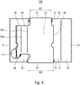
Fig. 4 is a left side view that shows the coil component according to the embodiments of the present application. -
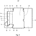
Fig. 5 is a right side view that shows the coil component according to the embodiments of the present application. -
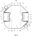
Fig. 6 is a plan (top) view that shows the coil component according to the embodiments of the present application. -
Fig. 7 is a bottom view that shows the coil component according to the embodiments of the present application. -
Fig. 8A is a plan (top) perspective view that shows the coil component according to the embodiments of the present application.Fig. 8B is a front perspective view that shows the coil component according to the embodiments of the present application. -
Fig. 9 is a cross-sectional view (a front cross-sectional view) along the line A - A shown inFig. 8A according to the embodiments of the present application. -
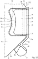
Fig. 10 is a partial enlarged plan (top) view that shows the coil component according to the embodiments of the present application. -
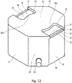
Fig. 11 is a perspective view that shows a core body (alternately, a core, a core molding, a core mold, or a molded core) and a protruding part (protrusion) of a coil of the coil component according to the embodiments of the present application. -
Fig. 12 is a plan (top) perspective view that shows the core body and the coil of the coil component according to the embodiments of the present application. -
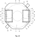
Fig. 13 is a bottom perspective view that shows the core body and the coil of the coil component according to the embodiments of the present application. -
Fig. 14 is a perspective view that shows a metal terminal of the coil component according to the embodiments of the present application. - Embodiments according to the present application are explained below with reference to
Figs. 1 - 14 . In regards to the embodiments, redundant explanations with respect to the same configurations are omitted but the same reference numerals are used for labeling in the drawings. - As shown in any drawing among
Figs. 1 - 14 , acoil component 100 according to the embodiments of the present application has a core body 10 (alternately, a core, a core molding, a core mold, or a molded core), acoil 60, and a metal terminal(s) 50. Specifically, thecore body 10 is formed of (made of or includes) a magnetic substance material (magnetic material). Thecoil 60 has an embeddedpart 61 that is embedded in the core body 10 (for instance, shown inFigs. 8A and9 ) and a protruding part(s) (a first protrudingpart 62 and a second protrudingpart 63, for instance, shown inFig. 8A ) that protrudes from thecore body 10. Further, themetal terminal 50 is electrically connected to the protruding part of thecoil 60. - The
core body 10 has a mounting surface 11 (for instance, shown inFig. 7 ), anupper surface 12, and a side surface(s). Specifically, theupper surface 12 faces an opposite side to the mountingsurface 11. In other words, the mountingsurface 11 and theupper surface 12 are outwardly opposite to each other. The side surfaces join (cross) (or are orthogonal to) the mountingsurface 11 and theupper surface 12. For instance, the side surfaces are afront surface 13, arear surface 14, aleft side surface 15, aright side surface 16, a frontleft surface 21, a rearleft surface 22, a rearright surface 23, and a frontright surface 24. - The
metal terminal 50 has a first planar part (first plate) 51, a second planar part (second plate) 52, and a third planar part (third plate) 53. Specifically, the firstplanar part 51 is arranged along the side surface of thecore body 10. The secondplanar part 52 is continuously connected to an upper end (edge) of the firstplanar part 51 and is arranged along theupper surface 12 of thecore body 10. Further, the thirdplanar part 53 is continuously connected to a lower end (edge) of the firstplanar part 51 and is arranged along the mountingsurface 11 of thecore body 10. The first, second, and thirdplanar parts planar parts - A leading edge (tip edge or forefront edge) of the second
planar part 52 is a first recess-shaped part (first arc-shaped part or first arc part) 52a (for instance, shown inFig. 8A ). Specifically, the first recess-shapedpart 52a is hollowed (recessed or depressed) toward an upper end (edge) side of the firstplanar part 51 and the leading edge of the first recess-shapedpart 52a is formed to be in a planar shape (arc-planar shape). The upper edge side of the firstplanar part 51 is a base end side of the secondplanar part 52. A recessedpart 30 is formed in theupper surface 12 of thecore body 10. The secondplanar part 52 is arranged in the recessedpart 30 of theupper surface 12. A second recess-shaped part (second arc-shaped part or second arc part) 30a (for instance, shown inFig. 8A ) of the recessedpart 30 corresponds to or is formed along the first recess-shapedpart 52a. The second recess-shapedpart 30a is formed to be in a planar shape (arc-planar shape) along the planar shape of the first recess-shapedpart 52a. In other words, the second recess-shapedpart 30a of the recessedpart 30 extends along a configuration (shape) of the first recess-shapedpart 52a as shown inFigs. 1 ,6 ,8A , and10 . - According to the embodiment of the present application, because the first recess-shaped
part 52a and the second recess-shapedpart 30a are provided, the area of a region that can be sucked (subject to a vacuum) by a suction nozzle of a mounter (not shown) can be sufficiently secured and ensured on theupper surface 12. Note that because a suction nozzle (a suction area of the suction nozzle) is generally in a circular shape (such as "R2" shown inFig. 8A ), the sucked region is efficiently secured on theupper surface 12 of thecore body 10. As a result, the suction of thecoil component 100 by the mounter can be performed more stably. - The
coil component 100 according to the embodiments of the present application is explained in detail below. Thecore body 10 is formed by a compression molding of powders including a magnetic substance material. During the process of the compression molding, the embeddedpart 61 of thecoil 60 is embedded into thecore body 10. - The shape of the
core body 10 is not particularly limited. However, for instance, thecore body 10 has the mountingsurface 11, theupper surface 12, and a plurality of side surfaces that are respectively orthogonal to the mountingsurface 11 and theupper surface 12. The mountingsurface 11 is formed to be flat except for, for instance, a pair of second recessedparts 40 described below. Theupper surface 12 is formed to be flat except for, for instance, a pair of (first) recessedparts 30. Further, theupper surface 12 is arranged in parallel to the mountingsurface 11. - For instance, the side surfaces of the
core body 10 has thefront surface 13, therear surface 14, theleft side surface 15, and theright side surface 16. Specifically, therear surface 14 is arranged in parallel to thefront surface 13 and faces the opposite side to thefront surface 13. Theleft side surface 15 is orthogonal to thefront surface 13 and therear surface 14. Further, theright side surface 16 is arranged in parallel to theleft side surface 15 and faces the opposite side to theleft side surface 15. - The
core body 10 has, for instance, the frontleft surface 21, the rearleft surface 22, the rearright surface 23, and the frontright surface 24 as the side surfaces. Specifically, the frontleft surface 21 is arranged between thefront surface 13 and theleft side surface 15 and connects thefront surface 13 with theleft side surface 15. The rearleft surface 22 is arranged between theleft side surface 15 and therear surface 14 and connects theleft side surface 15 with therear surface 14. The rearright surface 23 is arranged between therear surface 14 and theright side surface 16 and connects therear surface 14 with theright side surface 16. Further, the frontright surface 24 is arranged between theright side surface 16 and thefront surface 13 and connects theright side surface 16 with thefront surface 13. The frontleft surface 21 is, for instance, tilted relative to each of thefront surface 13 and theleft side surface 15 at an angle of 135 degrees. The rearleft surface 22 is, for instance, tilted relative to each of theleft side surface 15 and therear surface 14 at an angle of 135 degrees. The rearright surface 23 is, for instance, tilted relative to each of therear surface 14 and theright side surface 16 at an angle of 135 degrees. Further, the frontright surface 24 is, for instance, tilted relative to each of theright side surface 16 and thefront surface 13 at an angle of 135 degrees. For instance, all of the rearleft surface 22, the rearright surface 23, and the frontright surface 24 have the same shapes and the same sizes (the same areas). However, with respect to a width dimension, the frontleft surface 21 is smaller than the rearleft surface 22, the rearright surface 23, and the frontright surface 24 as shown inFig. 8A . With respect to an area, the frontleft surface 21 is smaller than the rearleft surface 22, the rearright surface 23, and the frontright surface 24. - Each of the
front surface 13, therear surface 14, theleft side surface 15, theright side surface 16, the frontleft surface 21, the rearleft surface 22, the rearright surface 23, and the frontright surface 24 is, for instance, formed to be flat. - In the present embodiment, a pair of left and right (first) recessed
parts 30 is formed on theupper surface 12. A pair of left and right second recessedparts 40 is formed on the mountingsurface 11. - As an example, the
coil 60 is configured by a single round wire. In this case, thecoil 60 has the embeddedpart 61 that is configured by winding the (single) round wire and a pair of protruding parts (the first protrudingpart 62 and the second protruding part 63) that protrude toward an outside in the radial direction from the embeddedpart 61. An axis direction of thecoil 60 is in the vertical direction. The first protrudingpart 62 is configured by one end of the (single) round wire. The second protrudingpart 63 is configured by the other end of the (single) round wire. The first protrudingpart 62 and the second protrudingpart 63 horizontally protrude from the embeddedpart 61. For instance, the first protrudingpart 62 and the second protrudingpart 63 mutually protrude in the opposite directions from the embeddedpart 61. The first protrudingpart 62 horizontally protrudes from, for instance, the lower part of the rearleft surface 22 of thecore body 10. The second protrudingpart 63 horizontally protrudes from, for instance, the lower part of the frontright surface 24 of thecore body 10. For instance, the protruding direction of the first protrudingpart 62 protruded from the rearleft surface 22 is orthogonal to the rearleft surface 22. The protruding direction of the second protrudingpart 63 protruded from the frontright surface 24 is orthogonal to the frontright surface 24. - Further, the
coil 60 is not limited to be configured by the single round wire according to the embodiments of the present application. However, thecoil 60 may be, for instance, an edgewise coil that is configured by winding a flat wire. - As shown in
Fig. 14 , themetal terminal 50 is, for instance, configured by a folding process of a single metal plate. - The
metal terminal 50 has the first planar part (first plate) 51, the second planar part (second plate) 52, and the third planar part (third plate) 53 that are respectively formed to be a flat-shaped plate. The secondplanar part 52 is continuously connected to the upper end of the firstplanar part 51 and is substantially orthogonal to the firstplanar part 51. The thirdplanar part 53 is continuously connected to the lower end of the firstplanar part 51 and is substantially orthogonal to the firstplanar part 51. The secondplanar part 52 and the thirdplanar part 53 are located at opposite positions to each other and are substantially parallel to each other (refer toFig. 9 ). - As shown in
Figs. 4 and5 , the first planar part(s) 51 is, for instance, formed to be in a rectangular shape that is vertically long. - As shown in
Fig. 6 , the second planar part(s) 52 is, for instance, formed to be in a rectangular shape that is longer in a front-rear direction than in a right-left direction in the plan view. However, the leading edge(s) of the second planar part(s) 52 is the first recess-shaped part(s) (first arc-shaped part or first arc part) 52a as explained above. Further, it is preferred that a lateral width dimension (in the sight-left direction) of the second planar part(s) 52 is, for instance, more than two times of a plate thickness of themetal terminal 50. It is also preferred that the lateral width dimension (in the sight-left direction) of the second planar part(s) 52 is, for instance, more than three times of the plate thickness of themetal terminal 50. As a result of setting the dimensions of the secondplanar part 52 as explained above, the bending (folding) process of themetal terminal 50 to form the secondplanar part 52 can be stably performed. - As shown in
Fig. 7 , the third planar part(s) 53 is, for instance, formed to be in a rectangular shape that is longer in the front-rear direction than in the right-left direction in the plan view. - Further, as shown in
Figs. 4 ,5 , and14 , themetal terminal 50 has a fourth planar part (fourth plate) 54 and a fifth planar part (fifth plate) 55. Specifically, the fourthplanar part 54 is continuously connected to aside edge 51a of the firstplanar part 51 and joins (crosses) the firstplanar part 51. The fifthplanar part 55 is continuously connected to a leading edge (tip edge or forefront edge) 54a of the fourthplanar part 54 and joins (crosses) the fourthplanar part 54. Because the fourthplanar part 54 and the fifthplanar part 55 are formed by the bending (folding) process of themetal terminal 50, theside edge 51a and theleasing edge 54a are folds or ridges of themetal terminal 50. The fourthplanar part 54 and the fifthplanar part 55 are also respectively formed to be a flat-shaped plate. As shown in such asFigs. 1 - 5 , each of the fourthplanar part 54 and the fifthplanar part 55 is, for instance, formed to be in a rectangular shape that is vertically long. - In the plan view, an angle between the first
planar part 51 and the fourthplanar part 54 is, for instance, set to be 135 degrees (refer to such asFig. 8A ). In the plan view, an angle between the fourthplanar part 54 and the fifthplanar part 55 is, for instance, set to be 90 degrees (refer to such asFig. 8A ). - The first
planar part 51, the fourthplanar part 54, and the fifthplanar part 55 are respectively vertically arranged or extend in the vertical (up and down) direction. The secondplanar part 52 and the thirdplanar part 53 are respectively substantially horizontally arranged or substantially extend in the horizontal direction. - A welded piece (welded strip) 56 is formed at a lower end part of the fifth
planar part 55. The welded piece(s) 56 is welded to the protruding part(s) (the first protrudingpart 62 and the second protruding part 63) of the coil 60 (refer to such asFig. 7 ). - In the present embodiment, the
coil component 100 has a pair of left and right metal terminals (first and second metal terminals) 50. For instance, the pair ofmetal terminals 50 are mutually formed to be in the same shapes and the same sizes. - The first
planar part 51 of one (the left side) of themetal terminals 50 is arranged along theleft side surface 15. The secondplanar part 52 of thismetal terminal 50 is arranged at or in the recessedpart 30 on the left side. The thirdplanar part 53 of thismetal terminal 50 is arranged at or in the second recessedpart 40 on the left side. The fourthplanar part 54 of thismetal terminal 50 on the left side is, for instance, arranged along the rearleft surface 22. Further, the fifthplanar part 55 of thismetal terminal 50 substantially vertically raises relative to (substantially uprises with respect to or substantially stands from) the rearleft surface 22. - The first
planar part 51 of the other (the right side) of themetal terminals 50 is arranged along theright side surface 16. The secondplanar part 52 of thismetal terminal 50 is arranged at or in the recessedpart 30 on the right side. The thirdplanar part 53 of thismetal terminal 50 is arranged at or in the second recessedpart 40 on the right side. The fourthplanar part 54 of thismetal terminal 50 on the right side is, for instance, arranged along the frontright surface 24.
Further, the fifthplanar part 55 of thismetal terminal 50 substantially vertically raises relative to (substantially uprises with respect to or substantially stands from) the frontright surface 24. - As explained above, the second recessed
parts 40 at or in which the thirdplanar parts 53 are arranged are formed on the mountingsurface 11. - Further, the fourth
planar parts 54 are arranged along the side surfaces of thecore body 10. The fifthplanar parts 55 raise relative to the side surfaces of thecore body 10. - Further, because the fifth
planar parts 55 raise from the side surfaces of thecore body 10, the satisfactory or excellent heat dissipation from the fifthplanar parts 55 can be realized. It is preferred that the vertical dimension (length) of each of the fifthplanar parts 55 is half or more of the vertical dimension (length or height) of thecore body 10. It is more preferred that the vertical dimension (length) of each of the fifthplanar parts 55 is two thirds or more of the vertical dimension (length or height) of thecore body 10. - For instance, the
metal terminal 50 is adhered and fixed to thecore body 10. For instance, as shown inFig. 9 , the firstplanar part 51 is in surface contact with the side surface of thecore body 10 and is surface-joined to thecore body 10 by an adhesive. - The welded
piece 56 of themetal terminal 50 on the left side is welded to one of the protruding parts (the first protruding part 62) of thecoil 60. Similarly, the weldedpiece 56 of themetal terminal 50 on the right side is welded to the other of the protruding parts (the second protruding part 63) of thecoil 60. - For instance, the welded
piece 56 and the first protrudingpart 62 of themetal terminal 50 on the left side are mutually welded at afirst welding part 71 that is in a spherical shape. Similarly, the weldedpiece 56 and the second protrudingpart 63 of themetal terminal 50 on the right side are mutually welded at asecond welding part 72 that is in a spherical shape. - As shown in
Figs. 11 and12 , the recessedpart 30 on the left side of the pair of left and right recessedparts 30 is arranged at the left end of theupper surface 12. The recessedpart 30 on the right side is arranged at the right end of theupper surface 12. - For instance, each of the recessed
parts 30 is configured with a first step 31 (a bottom surface), a first tilted (inclined) surface (wall) 32 (an upper tilted surface), asecond step 35, a second tiltedsurface 36, and a pair of vertical surfaces (walls) 37. Specifically, the first tiltedsurface 32 is arranged at the peripheral edge of the recessedpart 30. Thesecond step 35 is arranged at a lower step as compared with thefirst step 31. Further, the second tiltedsurface 36 is arranged between thefirst step 31 and thesecond step 35 and is tilted downward toward the side of thesecond step 35 from the side of thefirst step 31. - The
first step 31 occupies the most of the plane area of the recessedpart 30. A bottom surface of thefirst step 31 is substantially horizontally arranged. However, in the present embodiment, thefirst step 31 increases in depth as it becomes far from the side surface of thecore body 10. - The left edge of the
first step 31 of the recessedpart 30 on the left side linearly extends in the front-rear direction. Each of the front and rear edges of thefirst step 31 of the recessedpart 30 on the left side linearly extends in the right-left direction. Thesecond step 35 of the recessedpart 30 on the left side linearly extends in the front-rear direction along the left edge of thefirst step 31 of the recessedpart 30 on the left side, and at the same time, is substantially horizontally arranged. The left edge of thesecond step 35 of the recessedpart 30 on the left side serves as the upper edge of theleft side surface 15 at a position where the recessedpart 30 on the left side is formed. - Similarly, the right edge of the
first step 31 of the recessedpart 30 on the right side linearly extends in the front-rear direction. Each of the front and rear edges of thefirst step 31 of the recessedpart 30 on the right side linearly extends in the right-left direction. Thesecond step 35 of the recessedpart 30 on the right side linearly extends in the front-rear direction along the right edge of thefirst step 31 of the recessedpart 30 on the right side, and at the same time, is substantially horizontally arranged. The right edge of thesecond step 35 of the recessedpart 30 on the right side serves as the upper edge of theright side surface 16 at a position where the recessedpart 30 on the right side is formed. - In the plan view, the second tilted
surface 36 is arranged between thefirst step 31 and thesecond step 35. - The second tilted
surface 36 of the recessedpart 30 on the left side extends in the front-rear direction along the left edge of thefirst step 31 of the recessedpart 30 on the left side and is tilted downward toward the left side. - The first tilted
surface 32 of the recessedpart 30 on the left side is continuously arranged along the right edge, the front edge, and the rear edge of this recessedpart 30. - Similarly, the second tilted
surface 36 of the recessedpart 30 on the right side extends in the front-rear direction along the right edge of thefirst step 31 of the recessedpart 30 on the right side and is tilted downward toward the right side. - Similarly, the first tilted
surface 32 of the recessedpart 30 on the right side is continuously arranged along the left edge, the front edge, and the rear edge of this recessedpart 30. - Each of the first tilted
surfaces 32 is tilted to a direction in which the recessedpart 30 becomes smaller (narrow) toward the depth direction (downward) of each of the recessedparts 30. In other words, each of the first tiltedsurfaces 32 is tilted downward and inward with respect to the recessedpart 30. The first tiltedsurface 32 works as a draft angle when thecore body 10 is pulled (taken out) from a mold after being formed by a molding process. - At each of the recessed
parts 30, the lower end of the first tiltedsurface 32 is positioned at the same height position as the bottom surface of thefirst step 31. Thevertical surfaces 37, which are vertically arranged, are respectively arranged between both ends of thesecond step 35 and the second tiltedsurface 36 in the front-rear direction and the lower end of the first tiltedsurface 32. - The planar shape of the recessed
part 30 corresponds to the planar shape of the secondplanar part 52. Each of the secondplanar parts 52 enters into each of the recessedparts 30. - Further, as explained above, the leading edge of the second
planar part 52 of themetal terminal 50 is the first recess-shapedpart 52a. The first recess-shapedpart 52a is hollowed (recessed or depressed) toward the upper edge side of the firstplanar part 51 and is formed to be in the planar shape. - In other words, in the plan view, a right edge (the leading edge) of the second
planar part 52 of themetal terminal 50 on the left side is hollowed toward the left side. A left edge (the leading edge) of the secondplanar part 52 of themetal terminal 50 on the right side is hollowed toward the right side. More specifically, the right edge of the secondplanar part 52 of themetal terminal 50 on the left side is hollowed toward the left side in a circular arc shape (in an arc shape). The left edge of the secondplanar part 52 of themetal terminal 50 on the right side is hollowed toward the right side in the circular arc shape (in the arc shape). - Further, both ends of the leading edge of the second planar part 52 (in the present embodiment, the front and rear ends of the right edge of the second
planar part 52 on the left side and the front and rear ends of the left edge of the secondplanar part 52 on the right side) are respectively formed to be in a projecting circular arc shape toward the outside of the secondplanar part 52. - Further, with respect to the recessed
part 30, the portions that correspond to both ends of the leading edge of the secondplanar part 52 are respectively formed to be in the circular arc shape along both ends of the leading edge of the secondplanar part 52. As a result, in the configuration in which the second recess-shapedpart 30a is formed at the recessedpart 30 according to the present embodiment, such as a chipping of thecore body 10 can be suppressed, and at the same time, an interference of the secondplanar part 52 with thecore body 10 can also be suppressed. - Further, as explained above, with respect to each of the recessed
parts 30, the portion of the recessedparts 30 that corresponds to the first recess-shapedpart 52a is the second recess-shapedpart 30a that is formed to be in the planar shape along the first recess-shapedpart 52a. - In other words, the planar shape of the right edge of the
first step 31 of the recessedpart 30 on the left side and the planar shape of the portion that is arranged along the right edge of thefirst step 31 of the first tiltedsurface 32 of the recessedpart 30 on the left side are formed to be in the recessed shape that is hollowed toward the left side and is in a circular arc shape. - Similarly, the planar shape of the left edge of the
first step 31 of the recessedpart 30 on the right side and the planar shape of the portion that is arranged along the left edge of thefirst step 31 of the first tiltedsurface 32 of the recessedpart 30 on the right side are formed to be in the recessed shape that is hollowed toward the right side and is in a circular arc shape. - Further, the second recess-shaped
part 30a of the recessedpart 30 on the left side and the second recess-shapedpart 30a of the recessedpart 30 on the right side are mutually arranged on the same circumference in the plan view. In other words, these (two of) second recess-shapedparts 30a extend along the same circumference of a circle R1 (seeFig. 8A ) (are concentrically arranged) on theupper surface 12 of thecore body 10 in the plan view. - As explained above, the pair of recessed
parts 30 are formed in theupper surface 12. Thecoil 60 has the pair of protruding parts (the first protrudingpart 62 and the second protruding part 63). Thecoil component 100 has the pair ofmetal terminals 50. One of the pair ofmetal terminals 50 is electrically connected to one of the pair of protruding parts. The other of the pair ofmetal terminals 50 is electrically connected to the other of the pair of protruding parts. The secondplanar part 52 of one of the pair ofmetal terminals 50 is arranged at or in one of the pair of recessedparts 30. The secondplanar part 52 of the other of the pair ofmetal terminals 50 is arranged at or in the other of the pair of recessedparts 30. The second recess-shapedpart 30a of one of the pair of recessedparts 30 and the second recess-shapedpart 30a of the other of the pair of recessedparts 30 are mutually arranged on the same circumference in the plan view. In other words, these (two of) second recess-shapedparts 30a extend along the same circumference of a circle R1 (seeFig. 8A ) (are concentrically arranged) on theupper surface 12 of thecore body 10 in the plan view. - As a result, the circular region being surrounded by the second recess-shaped
parts 30a of the pair of recessedparts 30 on theupper surface 12 can be excellently sucked by a suction nozzle of a mounter. - Specifically, as shown in
Fig. 8A , the circular region being surrounded by two second recess-shapedparts 30a corresponds to the circle R1. Further, a circle R2 corresponds to, for example, a periphery of the suction nozzle of the mounter or the sucked region. - As shown in
Fig. 13 , the second recessedpart 40 on the left side of a pair of left and right second recessedparts 40 is arranged at the left end of the mountingsurface 11. The second recessedpart 40 on the right side is arranged at the right end of the mountingsurface 11. - For instance, each of the second recessed
parts 40 is configured with a first step 41 (a bottom surface), a first tilted surface (wall) 42 (a lower tilted surface), a pair of front and rear second tilted surfaces (walls) 43 (lower tilted surfaces), asecond step 45, a third tiltedsurface 46, and a pair of vertical surfaces (walls) 47. Specifically, the first tiltedsurface 42 and the pair of front and rear second tiltedsurfaces 43 are arranged at a peripheral edge of second recessedpart 40. Thesecond step 45 is arranged in the upward position (on the side of the upper surface 12) as compared with thefirst step 41. Further, the third tiltedsurface 46 is arranged between thefirst step 41 and thesecond step 45 and is tilted (tilted upward) toward the side of thesecond step 45 from the side of thefirst step 41. - The
first step 41 occupies the most of the plane area of the second recessedpart 40. A bottom surface of thefirst step 41 is substantially horizontally arranged. But, in the present embodiment, thefirst step 41 increases in depth as it becomes far from the side surface of thecore body 10. However, the bottom surface of thefirst step 41 is not limited to the above configuration and may be arranged horizontally (to be parallel to the mounting surface 11). - Each of the left and right edges of the
first step 41 of the second recessedpart 40 on the left side linearly extends in the front-rear direction. Each of the front and rear edges of thefirst step 41 of the second recessedpart 40 on the left side linearly extends in the right-left direction. Thesecond step 45 of the second recessedpart 40 on the left side linearly extends in the front-rear direction along the left edge of thefirst step 41 of the second recessedpart 40 on the left side, and at the same time, is substantially horizontally arranged. The left edge of thesecond step 45 of the second recessedpart 40 on the left side serves as the lower edge of theleft side surface 15 at a position where the second recessedpart 40 on the left side is formed. - Similarly, each of the left and right edges of the
first step 41 of the second recessedpart 40 on the right side linearly extends in the front-rear direction. Each of the front and rear edges of thefirst step 41 of the second recessedpart 40 on the right side linearly extends in the right-left direction. Thesecond step 45 of the second recessedpart 40 on the right side linearly extends in the front-rear direction along the right edge of thefirst step 41 of the second recessedpart 40 on the right side, and at the same time, is substantially horizontally arranged. The right edge of thesecond step 45 of the second recessedpart 40 on the right side serves as the lower edge of theright side surface 16 at a position where the second recessedpart 40 on the right side is formed. - In the plan view, the third tilted
surface 46 is arranged between thefirst step 41 and thesecond step 45. - The third tilted
surface 46 of the second recessedpart 40 on the left side extends in the front-rear direction along the left edge of thefirst step 41 of the second recessedpart 40 on the left side and is tilted upward toward the left side. The first tiltedsurface 42 of the second recessedpart 40 on the left side extends in the front-rear direction along the right edge of this second recessedpart 40. The second tiltedsurface 43 at the front side of the second recessedpart 40 on the left side extends in the right-left direction along the front edge of the second recessedpart 40 on the left side. The second tiltedsurface 43 at the rear side of the second recessedpart 40 on the left side extends in the right-left direction along the rear edge of the second recessedpart 40 on the left side. - Similarly, the third tilted
surface 46 of the second recessedpart 40 on the right side extends in the front-rear direction along the right edge of thefirst step 41 of the second recessedpart 40 on the right side and is tilted upward toward the right side. The first tiltedsurface 42 of the second recessedpart 40 on the right side extends in the front-rear direction along the left edge of this second recessedpart 40. The second tiltedsurface 43 at the front side of the second recessedpart 40 on the right side extends in the right-left direction along the front edge of the second recessedpart 40 on the right side. The second tiltedsurface 43 at the rear side of the second recessedpart 40 on the right side extends in the right-left direction along the rear edge of the second recessedpart 40 on the right side. - With respect to each of the second recessed
parts 40, the first tiltedsurface 42 and the pair of second tiltedsurfaces 43 are tilted to a direction in which the second recessedpart 40 becomes smaller toward the depth direction (upward) of each of the second recessedparts 40. The first tiltedsurface 42 and the pair of second tiltedsurfaces 43 work as draft angles when thecore body 10 is pulled (taken out) from a mold after being formed by s molding process. - At each of the second recessed
parts 40, the upper end of each of the second tilted surfaces 43 is positioned at the same height position as the bottom surface of thefirst step 41. Thevertical surfaces 47, which are vertically arranged, are respectively arranged between both ends of thesecond step 45 and the third tiltedsurface 46 in the front-rear direction and the upper ends of the second tilted surfaces 43. - The planar shape of the second recessed
part 40 corresponds to the planar shape of the thirdplanar part 53. Each of the thirdplanar parts 53 enters into each of the second recessedparts 40. - As shown in
Fig. 9 , for instance, the secondplanar part 52 is spaced apart from the bottom surface of the recessedpart 30. On the other hand, the thirdplanar part 53 comes in contact with the bottom surface of the second recessedpart 40, or alternatively, a distance between the thirdplanar part 53 and the bottom surface of the second recessedpart 40 is smaller than a distance between the secondplanar part 52 and the bottom surface of the recessedpart 30. - As a result, since the third
planar parts 53 work as mounting terminals, a position accuracy of the thirdplanar parts 53 can be improved. In addition, as mentioned above, the interferences between the secondplanar parts 52 and the recessed parts 30 (the core body 10) can be suppressed. - When the metal terminal(s) 50 is attached on (is assembled to) the
core body 10, for instance, the secondplanar part 52 is joined (caulked) by being pressed downward. Thesecond step 35 and the second tiltedsurface 36 are respectively arranged at the boundary part between theupper surface 12 and theleft side surface 15 and at the boundary part between theupper surface 12 and theright side surface 16. Therefore, when themetal terminal 50 is attached on (is assembled to) thecore body 10 and the secondplanar part 52 is joined (caulked) (by being pressed downward), the interferences between the secondplanar parts 52 and thecore body 10 can be suppressed. Further, as explained above, thefirst step 31 increases in depth as it becomes far from the side surface. Therefore, after the secondplanar part 52 is joined (caulked) to thecore body 10, it is possible to suppress a case in which the secondplanar part 52 is detached from the recessedpart 30 toward the outside. That is, it is possible to respectively suppress cases in which the secondplanar part 52 on the left side is detached from the recessedpart 30 on the left side in the left direction and the secondplanar part 52 on the right side is detached from the recessedpart 30 on the right side in the right direction. - Further, the
second step 45 and the third tiltedsurface 46 are respectively arranged at the boundary part between the mountingsurface 11 and theleft side surface 15 and at the boundary part between the mountingsurface 11 and theright side surface 16. Therefore, when the metal terminal(s) 50 is attached on (is assembled to) thecore body 10, the interferences between the thirdplanar parts 53 and thecore body 10 can be suppressed. - As explained above, the first tilted
surface 32 of the recessedpart 30 is tilted to the direction in which the recessedpart 30 becomes smaller toward the depth direction (downward) of the recessedpart 30. Similarly, the first tiltedsurface 42 and the pair of second tiltedsurfaces 43 of the second recessedpart 40 are tilted to the direction in which the second recessedpart 40 becomes smaller toward the depth direction (upward) of the second recessedpart 40. - However, in the present embodiment, the tilt angle of the first tilted
surface 32 is steeper (more acute) (closer to 90 degrees) than the tilt angle of each of the first tiltedsurface 42 and the second tilted surfaces 43. - As explained above, the upper tilted surface (the first tilted surface 32), which is tilted to the direction in which the recessed
part 30 becomes smaller toward the depth direction of the recessedpart 30, is formed on the peripheral edge of the recessedpart 30. The lower tilted surfaces (the first tiltedsurface 42 and the second tilted surfaces 43), which are tilted to the direction in which the second recessedpart 40 becomes smaller toward the depth direction of the second recessedpart 40, are formed on the peripheral edge of the second recessedpart 40. The tilt angle of the upper tilted surface is steeper (more acute) than the tilt angle of each of the lower tilted surfaces. - As a result, the area of the sucked region that can be sucked by a suction nozzle of a mounter can be secured more sufficiently on the
upper surface 12 of thecore body 10. - As shown in
Fig. 4 , a width dimension W1 (for instance, a width dimension in the front-rear direction) of the upper end of the firstplanar part 51 is smaller than a width dimension W2 (for instance, a width dimension in the front-rear direction) of the lower end of the firstplanar part 51. Therefore, the joining process (attaching process) (caulking process) of the secondplanar part 52 can be performed easily. - Further, the dimension of the second
planar part 52 is smaller than the dimension of the thirdplanar part 53 in the radial direction of thecoil component 100. Therefore, the area of the sucked region that can be sucked by the suction nozzle of the mounter can be secured more sufficiently on theupper surface 12 of thecore body 10. - Further, the first protruding
part 62 and the second protrudingpart 63 of thecoil 60 protrude from the lower part of thecore body 10. The first protrudingpart 62 and the second protrudingpart 63 are respectively electrically connected to each of themetal terminals 50 at the lower part of thecoil component 100. Therefore, the distance between each of the first protrudingpart 62 and the second protrudingpart 63 and each of the thirdplanar parts 53, which are mounting terminals, can be shorten. As a result, a direct current resistance (DCR) of thecoil component 100 is decreased. - In addition, the first protruding
part 62, the second protrudingpart 63, thefirst welding part 71, and thesecond welding part 72 are arranged at the lower part of thecoil component 100. Therefore, since a position of a center of gravity of thecoil component 100 can be more lowered, a vibration resistance of thecoil component 100 can be improved. - Further, applications or uses of the
coil component 100 are not particularly limited. However, for instance, thecoil component 100 according to the embodiments of the present application can be used as an inductor assembled in a vehicle. - The embodiments of the coil component are explained with reference to the drawings. However, these embodiments are examples of the present invention. Thus, it will be apparent that the same may be varied in many ways.
- The embodiments of the present application include the following technical ideas or technical concepts.
- <1> A coil component including:
- a core body formed of a magnetic material, the core body having:
- a mounting surface;
- an upper surface, the upper surface and the mounting surface being outwardly opposite to each other; and
- a first side surface joining the mounting surface and the upper surface;
- a coil having:
- an embedded part embedded in the core body; and
- a first protruding part protruding from the core body; and
- a first metal terminal electrically connected to the first protruding part of the coil, the first metal terminal having:
- a first plate arranged along the first side surface of the core body;
- a second plate continuously extending from an upper end of the first plate and arranged along the upper surface of the core body; and
- a third plate continuously extending from a lower end of the first plate and arranged along the mounting surface of the core body,
- wherein a leading edge of the second plate is recessed toward the upper end of the first plate to form a first arc-shaped part,
- the upper surface of the core body has a first recess in which the second plate is arranged, and
- the first recess has a second arc-shaped part at a portion facing the first arc-shaped part, and the second arc-shaped part extends along a contour of the first arc-shaped part.
- a core body formed of a magnetic material, the core body having:
- <2> The coil component according to <1>, further including:
- a second metal terminal having:
- a fourth plate arranged along a second side surface of the core body;
- a fifth plate continuously extending from an upper end of the fourth plate and arranged along the upper surface of the core body; and
- a sixth plate continuously extending from a lower end of the fourth plate and arranged along the mounting surface of the core body,
- wherein the second side surface of the core body joins the mounting surface and the upper surface,
- the coil has a second protruding part protruding from the core body, and the second metal terminal is electrically connected to the second protruding part,
- the upper surface of the core body has a second recess in which the fifth plate is arranged,
- a leading edge of the fifth plate is recessed toward the upper end of the fourth plate to form a third arc-shaped part,
- the second recess has a fourth arc-shaped part at a portion facing the third arc-shaped part, and the fourth arc-shaped part extends along a contour of the third arc-shaped part, and
the second arc-shaped part of the first recess and the fourth arc-shaped part of the second recess extend along a same circumference of a circle (are concentrically arranged) on the upper surface of the core body in a plan view.
- a second metal terminal having:
- <3> The coil component according to <1> or <2>, wherein the mounting surface has a third recess in which the third plate of the first metal terminal is arranged.
- <4> The coil component according to <3>,
wherein the second plate of the first metal terminal is spaced apart from a bottom of the first recess via a first distance,
the third plate of the first metal terminal contacts a bottom of the third recess or is spaced apart from the bottom of the third recess via a second distance, and the second distance is smaller than the first distance. - <5> The coil component according to <3> or <4>,
- wherein a first inner wall of the first recess is inwardly inclined by a first angle, and an area of a bottom of the first recess is smaller than an area of a top of the first recess,
- a second inner wall of the third recess is inwardly inclined by a second angle, and area of a bottom of the third recess is smaller than an area of a top of the third recess, and the first angle is more acute than the second angle.
- <6> The coil component according to any one of <1> - <5>,
- wherein the first metal terminal further has:
- a seventh plate continuously extending at an angle from a side edge of the first plate; and
- an eighth plate continuously extending at an angle from a leading edge of the seventh plate,
- the seventh plate extends along another side surface of the core body, and
- the eighth plate uprises with respect to the another side surface.
- wherein the first metal terminal further has:
- <7> The coil component according to <6>, further including:
- a welded piece provided at a lower end part of the eighth plate of the first metal terminal,
- wherein the welded piece is welded to the first protruding part of the coil.
- The coil component being thus described, it will be apparent that the same may be varied in many ways. Such variations are not to be regarded as a departure from the spirit and scope of the invention, and all such modifications as would be apparent to one of ordinary skill in the art are intended to be included within the scope of the following claims. Further, the above embodiments can be combined with each other and such combinations are not to be regarded as a departure from the spirit and scope of the invention.
Claims (7)
- A coil component comprising:a core body formed of a magnetic material, the core body having:a mounting surface;an upper surface, the upper surface and the mounting surface being outwardly opposite to each other; anda first side surface joining the mounting surface and the upper surface;a coil having:an embedded part embedded in the core body; anda first protruding part protruding from the core body; anda first metal terminal electrically connected to the first protruding part of the coil, the first metal terminal having:a first plate arranged along the first side surface of the core body;a second plate continuously extending from an upper end of the first plate and arranged along the upper surface of the core body; anda third plate continuously extending from a lower end of the first plate and arranged along the mounting surface of the core body,wherein a leading edge of the second plate is recessed toward the upper end of the first plate to form a first arc-shaped part,the upper surface of the core body has a first recess in which the second plate is arranged, andthe first recess has a second arc-shaped part facing the first arc-shaped part, and the second arc-shaped part extends along a contour of the first arc-shaped part.
- The coil component according to claim 1, further comprising:a second metal terminal having:a fourth plate arranged along a second side surface of the core body;a fifth plate continuously extending from an upper end of the fourth plate and arranged along the upper surface of the core body; anda sixth plate continuously extending from a lower end of the fourth plate and arranged along the mounting surface of the core body,wherein the second side surface of the core body joins the mounting surface and the upper surface,the coil has a second protruding part protruding from the core body, and the second metal terminal is electrically connected to the second protruding part,the upper surface of the core body has a second recess in which the fifth plate is arranged,a leading edge of the fifth plate is recessed toward the upper end of the fourth plate to form a third arc-shaped part,the second recess has a fourth arc-shaped part facing the third arc-shaped part, and the fourth arc-shaped part extends along a contour of the third arc-shaped part, and
the second arc-shaped part of the first recess and the fourth arc-shaped part of the second recess are concentrically arranged on the upper surface of the core body in a plan view. - The coil component according to claim 1 or 2,
wherein the mounting surface has a third recess in which the third plate of the first metal terminal is arranged. - The coil component according to claim 3,wherein the second plate of the first metal terminal is spaced apart from a bottom of the first recess via a first distance, andthe third plate of the first metal terminal contacts a bottom of the third recess or is spaced apart from the bottom of the third recess via a second distance, and the second distance is smaller than the first distance.
- The coil component according to claim 3 or 4,wherein a first inner wall of the first recess is inwardly inclined by a first angle, and an area of a bottom of the first recess is smaller than an area of a top of the first recess,a second inner wall of the third recess is inwardly inclined by a second angle, and area of a bottom of the third recess is smaller than an area of a top of the third recess, andthe first angle is more acute than the second angle.
- The coil component according to any one of claims 1 to 5, wherein the first metal terminal further has:a seventh plate continuously extending at an angle from a side edge of the first plate; andan eighth plate continuously extending at an angle from a leading edge of the seventh plate,the seventh plate extends along another side surface of the core body, and
the eighth plate uprises with respect to the another side surface. - The coil component according to claim 6, further comprising:a welded piece provided at a lower end part of the eighth plate of the first metal terminal,wherein the welded piece is welded to the first protruding part of the coil.
Applications Claiming Priority (1)
| Application Number | Priority Date | Filing Date | Title |
|---|---|---|---|
| JP2021011704A JP7643054B2 (en) | 2021-01-28 | 2021-01-28 | Coil parts |
Publications (2)
| Publication Number | Publication Date |
|---|---|
| EP4036942A1 true EP4036942A1 (en) | 2022-08-03 |
| EP4036942B1 EP4036942B1 (en) | 2025-03-05 |
Family
ID=79230907
Family Applications (1)
| Application Number | Title | Priority Date | Filing Date |
|---|---|---|---|
| EP22150166.1A Active EP4036942B1 (en) | 2021-01-28 | 2022-01-04 | Coil component |
Country Status (4)
| Country | Link |
|---|---|
| US (1) | US12230435B2 (en) |
| EP (1) | EP4036942B1 (en) |
| JP (1) | JP7643054B2 (en) |
| CN (1) | CN114823035A (en) |
Citations (5)
| Publication number | Priority date | Publication date | Assignee | Title |
|---|---|---|---|---|
| JP2005142459A (en) * | 2003-11-10 | 2005-06-02 | Toko Inc | Surface mount type inductor |
| JP2007273739A (en) | 2006-03-31 | 2007-10-18 | Tdk Corp | Coil parts |
| JP2017045758A (en) * | 2015-08-24 | 2017-03-02 | Tdk株式会社 | Coil device |
| US20180012699A1 (en) * | 2016-07-07 | 2018-01-11 | Tdk Corporation | Coil device |
| JP2021011704A (en) | 2019-07-04 | 2021-02-04 | 首都高メンテナンス西東京株式会社 | Guide display apparatus |
Family Cites Families (7)
| Publication number | Priority date | Publication date | Assignee | Title |
|---|---|---|---|---|
| JP2000151058A (en) * | 1998-11-09 | 2000-05-30 | Alps Electric Co Ltd | Surface mount electronic component |
| JP4823623B2 (en) * | 2005-09-15 | 2011-11-24 | Tdk株式会社 | Surface mount electronic component array |
| JP2008147349A (en) * | 2006-12-08 | 2008-06-26 | Murata Mfg Co Ltd | Electronic component |
| JP4636014B2 (en) * | 2006-12-26 | 2011-02-23 | Tdk株式会社 | Wire wound electronic components |
| JP4793663B2 (en) * | 2008-04-23 | 2011-10-12 | Tdk株式会社 | Coil parts |
| JP5935309B2 (en) * | 2011-12-15 | 2016-06-15 | スミダコーポレーション株式会社 | Coil parts |
| CN116348973A (en) * | 2020-10-30 | 2023-06-27 | 松下知识产权经营株式会社 | inductor |
-
2021
- 2021-01-28 JP JP2021011704A patent/JP7643054B2/en active Active
-
2022
- 2022-01-04 EP EP22150166.1A patent/EP4036942B1/en active Active
- 2022-01-04 US US17/567,948 patent/US12230435B2/en active Active
- 2022-01-21 CN CN202210073780.7A patent/CN114823035A/en active Pending
Patent Citations (5)
| Publication number | Priority date | Publication date | Assignee | Title |
|---|---|---|---|---|
| JP2005142459A (en) * | 2003-11-10 | 2005-06-02 | Toko Inc | Surface mount type inductor |
| JP2007273739A (en) | 2006-03-31 | 2007-10-18 | Tdk Corp | Coil parts |
| JP2017045758A (en) * | 2015-08-24 | 2017-03-02 | Tdk株式会社 | Coil device |
| US20180012699A1 (en) * | 2016-07-07 | 2018-01-11 | Tdk Corporation | Coil device |
| JP2021011704A (en) | 2019-07-04 | 2021-02-04 | 首都高メンテナンス西東京株式会社 | Guide display apparatus |
Also Published As
| Publication number | Publication date |
|---|---|
| JP7643054B2 (en) | 2025-03-11 |
| US20220238272A1 (en) | 2022-07-28 |
| JP2022115199A (en) | 2022-08-09 |
| CN114823035A (en) | 2022-07-29 |
| US12230435B2 (en) | 2025-02-18 |
| EP4036942B1 (en) | 2025-03-05 |
Similar Documents
| Publication | Publication Date | Title |
|---|---|---|
| JP6259222B2 (en) | Coil parts | |
| EP3671773B1 (en) | Coil component | |
| JP2011243703A (en) | Coil sealed dust core and method for manufacturing the same | |
| JP6288510B2 (en) | Reactor | |
| US12500025B2 (en) | Coil component | |
| CN107039769A (en) | A kind of manufacture method of antenna assembly and the antenna assembly | |
| EP4036942B1 (en) | Coil component | |
| JP3180254U (en) | Filter shell | |
| US20250246362A1 (en) | Coil component | |
| CN113140386B (en) | Coil device | |
| CN118522538A (en) | Transformer and method for manufacturing the same | |
| CN202352441U (en) | Filter shell | |
| JP4983389B2 (en) | Coil parts | |
| JP2022077899A (en) | Coil component | |
| US20240112850A1 (en) | Coil component | |
| JP2005285901A (en) | Electronic component and manufacturing method thereof | |
| JP2012235031A (en) | Manufacturing method of coil component | |
| JP4569533B2 (en) | Coil parts | |
| US11195662B2 (en) | Film capacitor with a film winding core having metallikon electrodes and busbars on its ends | |
| US20240134250A1 (en) | Base assembly of voice coil motor and voice coil motor | |
| JP2017135009A (en) | connector | |
| US20240021350A1 (en) | Inductor | |
| CN214177122U (en) | Base assembly of voice coil motor and voice coil motor | |
| CN219106568U (en) | Radio frequency switch assembly and radio frequency switch | |
| US20230368965A1 (en) | Coil component |
Legal Events
| Date | Code | Title | Description |
|---|---|---|---|
| PUAI | Public reference made under article 153(3) epc to a published international application that has entered the european phase |
Free format text: ORIGINAL CODE: 0009012 |
|
| STAA | Information on the status of an ep patent application or granted ep patent |
Free format text: STATUS: THE APPLICATION HAS BEEN PUBLISHED |
|
| AK | Designated contracting states |
Kind code of ref document: A1 Designated state(s): AL AT BE BG CH CY CZ DE DK EE ES FI FR GB GR HR HU IE IS IT LI LT LU LV MC MK MT NL NO PL PT RO RS SE SI SK SM TR |
|
| STAA | Information on the status of an ep patent application or granted ep patent |
Free format text: STATUS: REQUEST FOR EXAMINATION WAS MADE |
|
| 17P | Request for examination filed |
Effective date: 20230131 |
|
| RBV | Designated contracting states (corrected) |
Designated state(s): AL AT BE BG CH CY CZ DE DK EE ES FI FR GB GR HR HU IE IS IT LI LT LU LV MC MK MT NL NO PL PT RO RS SE SI SK SM TR |
|
| GRAP | Despatch of communication of intention to grant a patent |
Free format text: ORIGINAL CODE: EPIDOSNIGR1 |
|
| STAA | Information on the status of an ep patent application or granted ep patent |
Free format text: STATUS: GRANT OF PATENT IS INTENDED |
|
| INTG | Intention to grant announced |
Effective date: 20241031 |
|
| GRAS | Grant fee paid |
Free format text: ORIGINAL CODE: EPIDOSNIGR3 |
|
| GRAA | (expected) grant |
Free format text: ORIGINAL CODE: 0009210 |
|
| STAA | Information on the status of an ep patent application or granted ep patent |
Free format text: STATUS: THE PATENT HAS BEEN GRANTED |
|
| AK | Designated contracting states |
Kind code of ref document: B1 Designated state(s): AL AT BE BG CH CY CZ DE DK EE ES FI FR GB GR HR HU IE IS IT LI LT LU LV MC MK MT NL NO PL PT RO RS SE SI SK SM TR |
|
| REG | Reference to a national code |
Ref country code: GB Ref legal event code: FG4D |
|
| REG | Reference to a national code |
Ref country code: CH Ref legal event code: EP |
|
| REG | Reference to a national code |
Ref country code: IE Ref legal event code: FG4D |
|
| REG | Reference to a national code |
Ref country code: DE Ref legal event code: R096 Ref document number: 602022011266 Country of ref document: DE |
|
| PG25 | Lapsed in a contracting state [announced via postgrant information from national office to epo] |
Ref country code: RS Free format text: LAPSE BECAUSE OF FAILURE TO SUBMIT A TRANSLATION OF THE DESCRIPTION OR TO PAY THE FEE WITHIN THE PRESCRIBED TIME-LIMIT Effective date: 20250605 |
|
| PG25 | Lapsed in a contracting state [announced via postgrant information from national office to epo] |
Ref country code: FI Free format text: LAPSE BECAUSE OF FAILURE TO SUBMIT A TRANSLATION OF THE DESCRIPTION OR TO PAY THE FEE WITHIN THE PRESCRIBED TIME-LIMIT Effective date: 20250305 |
|
| REG | Reference to a national code |
Ref country code: NL Ref legal event code: MP Effective date: 20250305 |
|
| PG25 | Lapsed in a contracting state [announced via postgrant information from national office to epo] |
Ref country code: ES Free format text: LAPSE BECAUSE OF FAILURE TO SUBMIT A TRANSLATION OF THE DESCRIPTION OR TO PAY THE FEE WITHIN THE PRESCRIBED TIME-LIMIT Effective date: 20250305 |
|
| REG | Reference to a national code |
Ref country code: LT Ref legal event code: MG9D |
|
| PG25 | Lapsed in a contracting state [announced via postgrant information from national office to epo] |
Ref country code: NO Free format text: LAPSE BECAUSE OF FAILURE TO SUBMIT A TRANSLATION OF THE DESCRIPTION OR TO PAY THE FEE WITHIN THE PRESCRIBED TIME-LIMIT Effective date: 20250605 |
|
| PG25 | Lapsed in a contracting state [announced via postgrant information from national office to epo] |
Ref country code: HR Free format text: LAPSE BECAUSE OF FAILURE TO SUBMIT A TRANSLATION OF THE DESCRIPTION OR TO PAY THE FEE WITHIN THE PRESCRIBED TIME-LIMIT Effective date: 20250305 |
|
| PG25 | Lapsed in a contracting state [announced via postgrant information from national office to epo] |
Ref country code: LV Free format text: LAPSE BECAUSE OF FAILURE TO SUBMIT A TRANSLATION OF THE DESCRIPTION OR TO PAY THE FEE WITHIN THE PRESCRIBED TIME-LIMIT Effective date: 20250305 |
|
| PG25 | Lapsed in a contracting state [announced via postgrant information from national office to epo] |
Ref country code: BG Free format text: LAPSE BECAUSE OF FAILURE TO SUBMIT A TRANSLATION OF THE DESCRIPTION OR TO PAY THE FEE WITHIN THE PRESCRIBED TIME-LIMIT Effective date: 20250305 Ref country code: GR Free format text: LAPSE BECAUSE OF FAILURE TO SUBMIT A TRANSLATION OF THE DESCRIPTION OR TO PAY THE FEE WITHIN THE PRESCRIBED TIME-LIMIT Effective date: 20250606 |
|
| REG | Reference to a national code |
Ref country code: AT Ref legal event code: MK05 Ref document number: 1773743 Country of ref document: AT Kind code of ref document: T Effective date: 20250305 |
|
| PG25 | Lapsed in a contracting state [announced via postgrant information from national office to epo] |
Ref country code: NL Free format text: LAPSE BECAUSE OF FAILURE TO SUBMIT A TRANSLATION OF THE DESCRIPTION OR TO PAY THE FEE WITHIN THE PRESCRIBED TIME-LIMIT Effective date: 20250305 |
|
| PG25 | Lapsed in a contracting state [announced via postgrant information from national office to epo] |
Ref country code: SE Free format text: LAPSE BECAUSE OF FAILURE TO SUBMIT A TRANSLATION OF THE DESCRIPTION OR TO PAY THE FEE WITHIN THE PRESCRIBED TIME-LIMIT Effective date: 20250305 |
|
| PG25 | Lapsed in a contracting state [announced via postgrant information from national office to epo] |
Ref country code: SM Free format text: LAPSE BECAUSE OF FAILURE TO SUBMIT A TRANSLATION OF THE DESCRIPTION OR TO PAY THE FEE WITHIN THE PRESCRIBED TIME-LIMIT Effective date: 20250305 |
|
| PG25 | Lapsed in a contracting state [announced via postgrant information from national office to epo] |
Ref country code: PT Free format text: LAPSE BECAUSE OF FAILURE TO SUBMIT A TRANSLATION OF THE DESCRIPTION OR TO PAY THE FEE WITHIN THE PRESCRIBED TIME-LIMIT Effective date: 20250707 |
|
| PG25 | Lapsed in a contracting state [announced via postgrant information from national office to epo] |
Ref country code: PL Free format text: LAPSE BECAUSE OF FAILURE TO SUBMIT A TRANSLATION OF THE DESCRIPTION OR TO PAY THE FEE WITHIN THE PRESCRIBED TIME-LIMIT Effective date: 20250305 Ref country code: IT Free format text: LAPSE BECAUSE OF FAILURE TO SUBMIT A TRANSLATION OF THE DESCRIPTION OR TO PAY THE FEE WITHIN THE PRESCRIBED TIME-LIMIT Effective date: 20250305 |
|
| PG25 | Lapsed in a contracting state [announced via postgrant information from national office to epo] |
Ref country code: AT Free format text: LAPSE BECAUSE OF FAILURE TO SUBMIT A TRANSLATION OF THE DESCRIPTION OR TO PAY THE FEE WITHIN THE PRESCRIBED TIME-LIMIT Effective date: 20250305 |
|
| PG25 | Lapsed in a contracting state [announced via postgrant information from national office to epo] |
Ref country code: EE Free format text: LAPSE BECAUSE OF FAILURE TO SUBMIT A TRANSLATION OF THE DESCRIPTION OR TO PAY THE FEE WITHIN THE PRESCRIBED TIME-LIMIT Effective date: 20250305 Ref country code: CZ Free format text: LAPSE BECAUSE OF FAILURE TO SUBMIT A TRANSLATION OF THE DESCRIPTION OR TO PAY THE FEE WITHIN THE PRESCRIBED TIME-LIMIT Effective date: 20250305 |
|
| PG25 | Lapsed in a contracting state [announced via postgrant information from national office to epo] |
Ref country code: RO Free format text: LAPSE BECAUSE OF FAILURE TO SUBMIT A TRANSLATION OF THE DESCRIPTION OR TO PAY THE FEE WITHIN THE PRESCRIBED TIME-LIMIT Effective date: 20250305 |
|
| PG25 | Lapsed in a contracting state [announced via postgrant information from national office to epo] |
Ref country code: SK Free format text: LAPSE BECAUSE OF FAILURE TO SUBMIT A TRANSLATION OF THE DESCRIPTION OR TO PAY THE FEE WITHIN THE PRESCRIBED TIME-LIMIT Effective date: 20250305 |
|
| PG25 | Lapsed in a contracting state [announced via postgrant information from national office to epo] |
Ref country code: IS Free format text: LAPSE BECAUSE OF FAILURE TO SUBMIT A TRANSLATION OF THE DESCRIPTION OR TO PAY THE FEE WITHIN THE PRESCRIBED TIME-LIMIT Effective date: 20250705 |
|
| REG | Reference to a national code |
Ref country code: DE Ref legal event code: R097 Ref document number: 602022011266 Country of ref document: DE |
|
| PLBE | No opposition filed within time limit |
Free format text: ORIGINAL CODE: 0009261 |
|
| STAA | Information on the status of an ep patent application or granted ep patent |
Free format text: STATUS: NO OPPOSITION FILED WITHIN TIME LIMIT |
|
| PG25 | Lapsed in a contracting state [announced via postgrant information from national office to epo] |
Ref country code: DK Free format text: LAPSE BECAUSE OF FAILURE TO SUBMIT A TRANSLATION OF THE DESCRIPTION OR TO PAY THE FEE WITHIN THE PRESCRIBED TIME-LIMIT Effective date: 20250305 |
|
| REG | Reference to a national code |
Ref country code: CH Ref legal event code: L10 Free format text: ST27 STATUS EVENT CODE: U-0-0-L10-L00 (AS PROVIDED BY THE NATIONAL OFFICE) Effective date: 20260114 |
|
| 26N | No opposition filed |
Effective date: 20251208 |
|
| PGFP | Annual fee paid to national office [announced via postgrant information from national office to epo] |
Ref country code: GB Payment date: 20260123 Year of fee payment: 5 |
|
| PGFP | Annual fee paid to national office [announced via postgrant information from national office to epo] |
Ref country code: DE Payment date: 20260121 Year of fee payment: 5 |
|
| PGFP | Annual fee paid to national office [announced via postgrant information from national office to epo] |
Ref country code: FR Payment date: 20260123 Year of fee payment: 5 |