EP4036714B1 - Computerimplementiertes verfahren zur software-architekturanalyse und vorrichtung dafür - Google Patents
Computerimplementiertes verfahren zur software-architekturanalyse und vorrichtung dafür Download PDFInfo
- Publication number
- EP4036714B1 EP4036714B1 EP20877281.4A EP20877281A EP4036714B1 EP 4036714 B1 EP4036714 B1 EP 4036714B1 EP 20877281 A EP20877281 A EP 20877281A EP 4036714 B1 EP4036714 B1 EP 4036714B1
- Authority
- EP
- European Patent Office
- Prior art keywords
- call
- module
- architecture
- layer
- rule
- Prior art date
- Legal status (The legal status is an assumption and is not a legal conclusion. Google has not performed a legal analysis and makes no representation as to the accuracy of the status listed.)
- Active
Links
Images





Classifications
-
- G—PHYSICS
- G06—COMPUTING OR CALCULATING; COUNTING
- G06F—ELECTRIC DIGITAL DATA PROCESSING
- G06F8/00—Arrangements for software engineering
- G06F8/70—Software maintenance or management
- G06F8/75—Structural analysis for program understanding
-
- G—PHYSICS
- G06—COMPUTING OR CALCULATING; COUNTING
- G06F—ELECTRIC DIGITAL DATA PROCESSING
- G06F11/00—Error detection; Error correction; Monitoring
- G06F11/36—Prevention of errors by analysis, debugging or testing of software
- G06F11/3604—Analysis of software for verifying properties of programs
-
- G—PHYSICS
- G06—COMPUTING OR CALCULATING; COUNTING
- G06F—ELECTRIC DIGITAL DATA PROCESSING
- G06F8/00—Arrangements for software engineering
- G06F8/20—Software design
Definitions
- This application relates to the field of computer technologies, and in particular, to a computer implementation method for software architecture analysis, an apparatus for executing the method, and a computer system.
- US 2005/160411 A1 discloses a method and apparatus for managing, in a computer system, design of a software system.
- Various embodiments include receiving an input to the computer system specifying dependency relationships among subsystems of the software system and providing an output from the computer system responsive to the input.
- a rule is imposed on at least one of the dependency relationships and data for the rule is provided as part of the input.
- US 2012/054714 A1 discloses a system to generate an interactive layered visualization of a software system including a storage device to storage a model of the system that defines entities and relationships among entities.
- the system also includes a visualization tool to generate nodes representing the entities and assign nodes to layers in a set of ordered layers in accordance with rules associated with each layer.
- a layered layout of the software system is thereby generated and an interactive visualization of the layered layout is rendered for display to the user.
- US 2010/058288 A1 discloses a method for structuring a software implementation with a plurality of modules, for checking whether these modules fit a logical model.
- the logical model will be defined and consists of two independent dimensions comprising a technical dimension and a business-driven-dimension. Further, allowed dependencies between the elements of the logical model, namely layers and slices, will be defined.
- the modules of the software implementation will be assigned to the logical model while checking for any violations of the allowed dependencies. After assigning the modules to the logical model the logical model the logical model with the assigned modules will be visualised interactively and integrally and the allowed dependencies and any violations of the checked dependencies will be indicated.
- This application provides a computer implementation method for software architecture analysis, which improves efficiency of software architecture analysis and management.
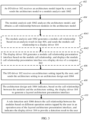
- a first aspect of this application provides a computer implementation method for software architecture analysis, where the method is implemented by using a computer, and the method includes the following steps:
- An architecture analysis module imports an architecture model, where the architecture model includes a each module is a software code set with a specific function, and plurality of modules, each module includes at least one file, and wherein the importing comprises receiving, by a communication interface of a computer, the architecture model and storing it in a memory of the computer.
- Each file may call a file of another module.
- a call between files is also referred to as a call between modules to which the files belong.
- the architecture analysis module analyzes files included in the plurality of modules to obtain module call information, where the module call information includes a call relationship between the plurality of modules.
- the architecture analysis module obtains an architecture setting by receiving an input by a user, wherein the architecture setting includes a layering rule and a call rule, the layering rule includes set information of a plurality of layers and a module included at each of the plurality of layers, and the call rule includes a call rule between modules located at different layers (inter-layer call rule) and/or a call rule between modules included at each layer (intra-layer call rule).
- the architecture setting includes a layering rule and a call rule
- the layering rule includes set information of a plurality of layers and a module included at each of the plurality of layers
- the call rule includes a call rule between modules located at different layers (inter-layer call rule) and/or a call rule between modules included at each layer (intra-layer call rule).
- the architecture analysis module indicates a display driver to generate a layered architecture presentation interface based on the layering rule and the module call information, where in the layered architecture presentation interface, each module is allocated to an area corresponding to a layer including the module.
- the architecture analysis module detects the module call information based on the call rule, and displays a detection result by using the layered architecture presentation interface. That is, the architecture analysis module indicates the display driver to display the detection result in the layered architecture presentation interface.
- the architecture analysis module is used to analyze the call relationship between the modules, detect a matching degree between the call relationship and the call rule, and visually displays a detection result on an interface, so that efficiency of architecture analysis and architecture management is improved, and difficulty in architecture analysis and architecture management is reduced.
- the architecture analysis module further indicates the display driver to generate a module call relationship interface, and displays the call relationship between the modules on the module call relationship interface.
- the module call relationship interface is shown by using an interface, so that a user can visually obtain a call relationship between the modules in the architecture model, and operation difficulty of architecture analysis is reduced.
- the set information of the plurality of layers includes a sequence number of each layer; and in the layered architecture presentation interface, a location of each layer is set based on the sequence number of the layer. For example, a layer with a smaller sequence number is lower in the layered architecture presentation interface, or a layer with a larger sequence number is lower in the layered architecture presentation interface.
- the set information of the plurality of layers further includes an identity ID of each layer, and in the layered architecture presentation interface, the ID of each layer is set in a corresponding area of the layer.
- the analyzing files included in the plurality of modules to obtain module call information includes: counting a quantity of times that a file included in each module calls a file included in another module, to obtain a quantity of times of calls between the plurality of modules. Counting the quantity of times of calls between the plurality of modules helps effectively manage calls between the modules.
- the quantity of times of calls between the plurality of modules is displayed in the layered architecture presentation interface.
- the quantity of times of calls between the plurality of modules is displayed in a visual manner, thereby implementing better management of calls between the modules.
- the quantity of times of calls between the modules is also displayed in the interface, so that a user can obtain an analysis result of the architecture more intuitively and quickly, thereby improving efficiency of subsequent architecture management.
- the call relationship between the modules is shown by using a visual graph, so that readability of an architecture analysis result is further improved, and complexity in architecture analysis and management is reduced.
- the call rule between modules located at different layers includes any one or more of the following: an adjacent-layer call rule, a cross-layer call rule, and a reverse call rule.
- the adjacent-layer call rule indicates whether a call between modules at layers with adjacent layer sequence numbers is allowed.
- the cross-layer call rule indicates whether a call between modules at layers with non-adjacent layer sequence numbers is allowed.
- the reverse call rule indicates whether a module at a lower layer in the software architecture calls a module at an upper layer in the software architecture is allowed.
- the intra-layer call rule indicates whether a call between modules at a same layer is allowed.
- a call rule is generally formulated by a user based on a requirement of a software architecture design.
- the user may see, in a detection result, a degree of compliance between the architecture model and the design requirement, so as to subsequently improve the architecture model.
- the architecture analysis module may further detect a loop call, and display a detection result of the loop call by using the layered architecture presentation interface.
- An inter-module loop call indicates that one module is called by another module called by the module.
- colors of areas corresponding to adjacent layers are different.
- textures of areas corresponding to adjacent layers are different.
- Different presentation manners are used for areas corresponding to adjacent layers, so that the user can distinguish between different areas in the interface more conveniently, and efficiency of architecture management is improved.
- a second aspect of this application provides a software architecture analysis apparatus, including: a module analysis unit, an architecture design unit, and a rule detection unit.
- the module analysis unit is configured to import an architecture model, where the architecture model each module is a software code set with a specific function, and includes a plurality of modules, each module includes at least one file, and wherein the importing comprises receiving, by a communication interface of a computer, the architecture model and storing it in a memory of the computer; and analyze files included in the plurality of modules to obtain module call information, where the module call information includes a call relationship between the plurality of modules.
- the architecture design unit is configured to obtain an architecture setting by receiving an input by a user, wherein the architecture setting includes a layering rule and a call rule, the layering rule includes set information of a plurality of layers and a module included at each of the plurality of layers, and the call rule includes a call rule between modules located at different layers and/or a call rule between modules included at each layer; and indicate a display driver to generate a layered architecture presentation interface based on the layering rule and the module call information, where in the layered architecture presentation interface, each module is allocated to an area corresponding to a layer including the module.
- the rule detection unit is configured to detect the module call information based on the call rule, and display a detection result by using the layered architecture presentation interface.
- the rule detection unit indicates, based on the detection result, a display driver to display the detection result in the layered architecture presentation interface.
- the set information of the plurality of layers includes a sequence number of each layer; and in the layered architecture presentation interface, a location of each layer is set based on the sequence number of the layer.
- the module analysis unit is configured to count a quantity of times that a file included in each module calls a file included in another module, to obtain a quantity of times of calls between the plurality of modules.
- the quantity of times of calls between the plurality of modules is displayed in the layered architecture presentation interface.
- the module analysis unit is configured to count a quantity of times that a file included in each module calls a file included in another module, to obtain a quantity of times of calls between the plurality of modules.
- the call relationship between the plurality of modules is displayed by using an arrow in the layered architecture presentation interface.
- the rule detection unit is further configured to indicate the display driver to change, in the layered architecture presentation interface, a color and/or a format of an arrow corresponding to a call that is between modules and that violates the call rule.
- the call rule between modules located at different layers includes any one or more of the following: an adjacent-layer call rule, a cross-layer call rule, and a reverse call rule.
- colors of areas corresponding to adjacent layers are different.
- textures of areas corresponding to adjacent layers are different.
- the second aspect and the possible implementations of the second aspect correspond to the first aspect and the possible implementations of the first aspect. Therefore, technical effects of the second aspect and the possible implementations of the second aspect are not described herein again.
- a third aspect of this application provides a computer system, including at least one computer, where each computer includes a processor and a memory.
- the processor of the at least one computer is configured to access instructions in the memory of the at least one computer to perform the method provided in the first aspect and the possible implementations of the first aspect.
- a fourth aspect of this application provides a non-transient computer-readable storage medium.
- the storage medium stores program instructions.
- the storage medium includes but is not limited to a volatile memory, for example, a random access memory, and a nonvolatile memory, for example, a flash memory, a hard disk drive (hard disk drive, HDD), and a solid-state drive (solid-state drive, SSD).
- a fifth aspect of this application provides a computer program product.
- the computer system When instructions included in the computer program product are executed by a computer system, the computer system performs the method provided in the first aspect and the possible implementations of the first aspect.
- the computer program product may be a software installation package.
- the computer program product may be downloaded, and instructions included in the computer program product may be executed on the computer system.
- a software architecture analysis system 100 includes an input/output (input output, IO) driver 102, a display driver 104, and an architecture analysis apparatus 106.
- the architecture analysis apparatus 106 includes a module analysis unit 1062, an architecture design unit 1064, a rule detection unit 1066, and a report generation unit 1068.
- the foregoing apparatuses and units may be software apparatuses/units, and functions of the apparatuses and units are implemented by using software instructions.
- the I/O driver 102 is configured to manage an I/O device of a computer, and receive, by using the I/O device, various types of information input by a user.
- the display driver 104 has a capability of rendering an interface based on various types of information and controlling a display device to display a rendering result.
- each apparatus in the software architecture analysis system 100 has two deployment manners.
- the I/O driver 102, the display driver 104, and the architecture analysis apparatus 106 are all deployed on a same computer.
- the software analysis system 100 is generally provided as a software analysis tool for a user, and the user deploys the entire software architecture analysis system 100 on a local computer.
- an I/O driver 102 and a display driver 104 are deployed in each computer 202, and an architecture analysis apparatus 106 is deployed in a cluster of computers 204.
- the computer 202 is connected to the cluster of computers 204 by using a communication network.
- the computer 202 is a user-side computer, and the cluster of computers 204 is a remote computer.
- the computer may be, for example, a smartphone (smart phone), a personal digital assistant (personal digital assistant, PDA), a tablet computer, a laptop computer (laptop computer), a personal computer (personal computer, PC), or a server.
- the communication network may be a wired communication network, or a wireless communication network, for example, a 5 th generation (5 th Generation, 5G) mobile communication technology system, a long term evolution (long term evolution, LTE) system, or wireless fidelity (wireless fidelity, Wi-Fi).
- 5G 5 th generation
- LTE long term evolution
- Wi-Fi wireless fidelity
- each computer 204 may be deployed with the module analysis unit 1062, the architecture design unit 1064, the rule detection unit 1066, and the report generation unit 1068.
- some of the module analysis unit 1062, the architecture design unit 1064, the rule detection unit 1066, and the report generation unit 1068 are deployed in each computer 204, and all units of the architecture analysis apparatus 106 are deployed in the cluster of computers 204.
- the cluster of computers 204 as a whole provides a function of the architecture analysis apparatus 106 for the user-side computer 202.
- the architecture analysis apparatus 106 runs on a plurality of computers 204 in a distributed mode, providing an architecture analysis service with higher performance.
- an architecture analysis service is generally provided as a remote service, for example, a cloud service, for a user to use.
- the user can obtain the architecture analysis service by only deploying the I/O driver 102 and the display driver 104 on a local computer.
- the I/O driver 102 and the display driver 104 are parts of a client of the architecture analysis service.
- a software architecture analysis method is described below with reference to FIG. 3 to FIG. 8 .
- Step 402 An I/O driver 102 receives an architecture model input by a user, and sends the architecture model to a module analysis unit 1062.
- the architecture model includes software architecture-related information generated in a software development process.
- the architecture model includes a plurality of modules of a software architecture, where a file included in each module records a call by the file to a file in another module.
- a module is a software code set with a specific function, such as a component (component)/a service (service).
- the component may be an independent entity that is logically divided in the C/C++ language, and a file included in the component may be a .h file, a .so file, a .dll file, or the like.
- the service refers to a module that can be independently deployed and run in a service-oriented scenario. Services coordinate and cooperate with each other to provide a logical service function for a user. Each service runs in its own independent process, and services collaborate with each other by using a lightweight communication mechanism (usually a RESTful API based on an HTTP protocol).
- Each module includes at least one file.
- a file included in one module may call a file in another module.
- a module A includes header files, such as math.h and stdio.h, and a file of a module B calls both of the header files.
- the files stdio.h and math.h are called by the file of the module B by using instructions "#include ⁇ stdio.h>" and "#include ⁇ math.h>". In this case, it is considered that the file in the module B calls the file in the module A two times, and it is also considered that the module B calls the module A two times.
- a call by the module B to the module A is indicated by an arrow from the module B to the module A.
- One module may include one or more files, and each file may call one or more files in another module. Therefore, one module may call another module once or more times.
- a module analysis unit 1062 counts a quantity of times that a file included in each module calls a file included in another module, to obtain a quantity of times of calls between a plurality of modules. For example, if the module B includes 10 files, and each of the 10 files calls the files math.h and stdio.h, the module B calls the module A for 20 times.
- a number above an arrow that presents a call by the module B to the module A indicates a quantity of times that the module B calls the module A.
- Step 404 The module analysis unit 1062 imports the architecture model, analyzes the architecture model, and obtains module call information in the architecture model, where the module call information includes a call relationship between modules.
- the module call information further includes a quantity of times of calls between modules.
- step 4041 and step 4042 may be performed.
- Step 4041 The module analysis unit 1062 generates the module call information based on an analysis result in step 404, and sends the module call information to a display driver 104.
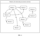
- Step 4042 The display driver 104 generates a module call information presentation interface based on the module call information, and displays the module call information presentation interface on a display device of a computer 202.
- the call relationship between modules is displayed by using an arrow.
- a call relationship between a module 1 and a module 3 in the figure is used as an example.
- An arrow (an arrow points from the module 1 to the module 3) is provided between the module 1 and the module 3, and a quantity of times of calls is marked as 78. This indicates that the module 1 calls the module 3 for 78 times in total.
- the analysis result obtained by the module analysis unit 1062 in step 404 further includes the quantity of times of calls between modules
- the quantity of times of calls between the modules is further displayed by using a number above an arrow in the module call information presentation interface.
- the module call information is obtained by using the module analysis unit 1062, the module call information is displayed to the user through the interface, thereby improving understanding of the architecture model by the user and reducing costs of analyzing a software architecture for the user.
- Step 406 The I/O driver 102 receives an architecture setting input by the user, and sends the architecture setting to an architecture design unit 1064.
- modules included in the architecture model To further manage modules, the user needs to perform layered management on the modules included in the architecture model. Generally, functions of modules included at each layer are similar, and a set of modules at each layer implements a logical function for the user.
- a common layering method includes a four-layer architecture, including a representation layer, an application layer, a business logic layer, and a persistence layer.
- the representation (user interface, UI) layer is used to receive a request of the user, return data to the user, and provide an interactive operation interface for the user.
- the application layer also referred to as a service layer
- the business logic (business logic, BL) layer (also referred to as a domain layer) is used to embody a user request, that is, parse the user request into a specific operation at a data access layer.
- the data access (data access, DA) layer also referred to as a persistence layer
- the data access layer generally includes modules such as a database and a file system.
- Another common layering method includes a three-layer architecture, including a data access layer, a business logic layer, and a representation layer.
- a three-layer architecture is used for presentation.
- the business logic layer in the three-layer architecture may be formed by combining the application layer and the business logic layer in the four-layer architecture.
- a total quantity of layers, a layer sequence number, a layer identity (identity, ID), and a function of each layer can be changed based on different service requirements and user design habits.
- the architecture setting includes a layering rule and a call rule that are included in the architecture model imported to the architecture analysis apparatus 106 in step 402.
- the layering rule includes set information of a plurality of layers, for example, a layer sequence number, a layer ID, and a module included at each of the plurality of layers.
- a layer sequence number of a layer is used to indicate a location of the layer in the software architecture.
- the architecture analysis apparatus 106 sets a location of each layer in the layered architecture presentation interface based on the layer sequence number. For example, a sequence number of the UI layer is 3, a sequence number of the BL layer is 2, and a sequence number of the DA layer is 1. Under this numbering rule, a layer with a larger layer sequence number is closer to the user, and a layer with a smaller layer sequence number is farther away from the user and closer to the bottom layer. For another example, a sequence number of the UI layer is 1, a sequence number of the BL layer is 2, and a sequence number of the DA layer is 3.
- a layer with a smaller layer sequence number is closer to the user, and a layer with a larger layer sequence number is farther away from the user and closer to the bottom layer.
- the former numbering rule is used below.
- the modules included at each layer are used to allocate the modules included in the architecture model obtained in step 402 to the layers.
- a layer ID and modules included at each layer are correspondingly recorded in an architecture setting, for example, layer ID 1: module 1/ module 2/ module 3, which indicates that a layer whose ID is 1 includes the module 1, the module 2, and the module 3.
- the call rule includes a call rule between modules located at different layers and/or a call rule between modules included at each layer.
- the call rule between modules included at each layer is also referred to as an intra-layer call rule.
- the call rule between modules of different layers can be any or more of the following: an adjacent-layer call rule, a cross-layer call rule, and a reverse call rule.
- the call rule may further include another rule that indicates a call between modules at a same layer/different layers.
- the intra-layer call rule indicates whether a call between modules at a same layer is allowed.
- the adjacent-layer call rule indicates whether a call between modules at layers with adjacent layer sequence numbers is allowed.
- the cross-layer call rule indicates whether a call between modules at layers with non-adjacent layer sequence numbers is allowed.
- the reverse call rule indicates whether a module at a lower layer in the software architecture calls a module at an upper layer in the software architecture is allowed. Under the foregoing former numbering rule, a sequence number of a lower layer in the software architecture is smaller.
- the user may use the I/O driver 102 to send an instruction that carries the architecture setting to the architecture design unit 1064, for example, an application programming interface (application programming interface, API) instruction.
- an application programming interface application programming interface, API
- the architecture design unit 1064 indicates the display driver 104 to generate an architecture setting interface.
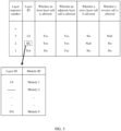
- the user can enter an architecture setting by editing a visual interface, so that the user can quickly set a layer sequence number, a layer ID, a module included at each layer, and a call rule. For example, if the user taps the "+" symbol in a layer sequence number column of the architecture setting interface, the architecture setting interface will automatically generate a row of configuration corresponding to a next layer sequence number. In a row corresponding to each layer sequence number, the customer can enter a layer ID and a call rule. Further, after the user taps a layer ID, a module configuration sub-interface will pop up in the architecture setting interface. In the module configuration sub-interface, the user may map each module imported in step 402 to a layer ID. Therefore, the user can configure the module included at each layer by using the module configuration sub-interface.
- the user has set the DA layer, the BL layer, and the UI layer, and their layer sequence numbers are respectively 1, 2, and 3.
- Call rules of the DA layer are as follows: an intra-layer call is not allowed, an adjacent-layer call is allowed, a cross-layer call is not allowed, and a reverse call is not allowed.
- Call rules of the BL layer are as follows: an intra-layer call is allowed, an adjacent-layer call is allowed, and a reverse call is not allowed. Because the software architecture has only three layers, there is no possibility of a cross-layer call at the BL layer. Therefore, the cross-layer call column corresponding to the BL layer is Null (null).
- Call rules of the UI layer are as follows: an intra-layer call is allowed, an adjacent-layer call is allowed, and a cross-layer call is not allowed. Because the UI layer is the top layer in the software architecture, there is no possibility of a reverse call to a higher layer. Therefore, the reverse call column corresponding to the UI layer is Null.
- the module configuration sub-interface of the BL layer is entered.
- the module configuration sub-interface it can be seen that some modules have been allocated to the UI layer and the DA layer. Therefore, the user can allocate the remaining modules to the BL layer.
- a specific allocation method may be filling BL in a layer ID corresponding to a module ID.
- architecture modules include modules 1 to 9, where the UI layer includes the module 1, the module 4, and the module 6, the BL layer includes the module 2, the module 8, and the module 7, and the DA layer includes the module 5, the module 3, and the module 9.
- Step 408 The architecture design unit 1064 indicates, based on the module call information and a layering rule, the display driver 104 to generate a layered architecture presentation interface.
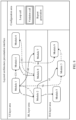
- a layered architecture presentation interface In the layered architecture presentation interface, areas corresponding to different layers are divided based on the layer sequence number and the layer ID.
- the module included at each layer is set in an area of the layer. Generally, a location of an area corresponding to a layer that is closer to the user is higher in the layered architecture presentation interface.
- a layered architecture presentation interface includes a UI layer area, a BL layer area, and a DA layer area. Deployment locations of the modules in FIG. 4 are re-deployed based on modules included at each layer in an architecture setting, and a call relationship between modules and a quantity of times of calls between the modules in FIG. 4 are inherited in FIG. 6 .
- different colors may be used to represent adjacent layer areas (not shown in the figure).
- a same color may be used to represent non-adjacent layer areas (not shown in the figure).
- Different colors are used to represent areas corresponding to adjacent layers, so as to improve user experience and help the user to distinguish between different layer areas.
- different background textures may be used to represent adjacent layer areas (not shown in the figure).
- a same background texture may be used to represent non-adjacent layer areas (not shown in the figure).
- Different background textures are used to represent adjacent layer areas, so as to improve user experience and help the user to distinguish between different layer areas.
- a blank area may be included between the adjacent layer areas, so as to help the user to distinguish between different layer areas.
- the layered architecture presentation interface further includes an operation area, and the operation area includes at least one operation entry.
- the operation entry includes one or more of the following: "violation call” and "report generation”.
- a loop call operation entry may be provided in the operation area.
- the loop call between modules indicates that one module is called by another module that is called by the module, that is, each of the two modules includes a file that is called by the other module, so that a loop is formed.
- the module call relationship presentation interface in FIG. 4 is used as an example.
- the module 1 and the module 2 call each other, that is, each of the module 1 and the module 2 includes a file called by the other module, so that a loop call is formed between the module 1 and the module 2.
- Step 410 The rule detection unit 1066 detects the module call information based on different operation entries tapped by the user in the operation area of the layered architecture presentation interface, and indicates the display driver 104 to provide a detection result to the user.
- the rule detection unit 1066 detects, based on the module call information, whether a loop call exists between two modules. If a loop call exists between two modules, the display driver 104 is indicated to display the detection result in the layered architecture presentation interface. For example, a dialog box pops up in the layered architecture presentation interface, and IDs of modules that have a loop call are displayed in the dialog box. For another example, colors of modules that have a loop call are changed in the layered architecture presentation interface. For another example, a color of an arrow between modules that have a loop call is changed in the layered architecture presentation interface.
- a format of an arrow between modules that have a loop call is changed in the layered architecture presentation interface, for example, changed from a solid line to a dashed line.
- a loop call exists between the module 1 and the module 2
- an arrow between the module 1 and the module 2 changes from a solid line to a dashed line.
- the rule detection unit 1066 detects, based on the module call information, whether a call that does not comply with a call rule exists between two modules. If a call that does not comply with a call rule exists between two modules, the display driver 104 is indicated to display the detection result in the layered architecture presentation interface. For example, a dialog box pops up in the layered architecture presentation interface, and IDs of modules that have a call that does not comply with a call rule and a specific call rule that is not complied with are displayed in the dialog box. For another example, colors of modules that have a call that does not comply with a call rule are changed in the layered architecture presentation interface.
- a color of an arrow between modules that have a call that does not comply with a call rule is changed in the layered architecture presentation interface.
- a format of an arrow between modules that have a call that does not comply with a call rule is changed in the layered architecture presentation interface, for example, changed from a solid line to a dashed line.
- a call by the module 2 to the module 1 does not comply with the call rule of the BL layer that a reverse call is not allowed. Therefore, after the user taps "violation call", an arrow of the call by the module 2 to the module 1 is changed from a solid line to a dashed line.
- a call by the module 8 to the module 6 does not comply with the call rule of the BL layer that a reverse call is not allowed. Therefore, after the user taps "violation call”, an arrow of the call by the module 8 to the module 6 is changed from a solid line to a dashed line.
- a call by the module 1 to the module 3 does not comply with the call rule of the UI layer that a cross-layer call is not allowed.
- the foregoing manner of displaying the detection result in the layered architecture presentation interface is merely an example.
- the detection result may be provided to the user in another manner.
- the rule detection unit 1066 indicates, based on the module call information and the call rule, the display driver 104 to generate a detection report and provides the detection report to the user.
- the detection report may include any one or more of the following: module call information, a detection result of a loop call, a detection result of a violation call, and a modification suggestion for a call relationship between modules.
- step 4041 and step 4012 may be first performed, and then step 406 to step 410 are performed. That is, the module call information presentation interface is first displayed to the user, and then the layered architecture presentation interface is displayed to the user.
- step 406 to step 410 may be directly performed without performing step 4041 and step 4012. That is, the module call information presentation interface does not need to be displayed to the user; and the architecture setting is directly obtained, and then the layered architecture presentation interface is displayed to the user based on the architecture setting.
- the modules are layered and displayed in different layer areas by using the layered architecture presentation interface, and the detection result of the call rule is also displayed to a user through the interface, so that the user can intuitively obtain a difference between the architecture model and the architecture setting, costs for the user to analyze a software architecture are reduced and an updating speed for an architecture module is improved.
- the user may clearly learn of, by using the detection result, a conflict between the architecture model developed by the user and both of the call rule and module layering designed by the user, and may further modify the architecture model based on the detection result. Further, the user may re-input a modified architecture model into the module analysis unit 1062 by using the I/O driver 102, so as to re-perform the software architecture analysis method provided in FIG. 3 on the modified architecture model, to further determine whether the modified architecture module conforms to the user design.
- an architecture analysis apparatus 106 may simultaneously provide the user with a module call information presentation interface and an analysis architecture presentation interface that are corresponding to the architecture model before being modified and a module call information presentation interface and an analysis architecture presentation interface that are corresponding to the architecture model after being modified.
- FIG. 9 provides a computer 202. At least one computer 202 provided in FIG. 9 is deployed in the computer system. The computer 202 is applied to the first deployment manner described above.
- the computer 202 includes a bus 2023, a processor 2021, a communication interface 2022, a display device 2025, and a memory 2024.
- the processor 2021, the memory 2024, the display device 2025, and the communication interface 2022 communicate with each other by using the bus 2023.
- the communication interface 2022 is configured to communicate with the outside, for example, receive an architecture model and an architecture setting, and store the architecture model in the memory 2024.
- the processor 2021 may be implemented by using a general-purpose central processing unit (English: central processing unit, CPU for short), a field programmable gate array (Field Programmable Gate Array, FPGA), or another programmable logic device.
- the memory 2024 may include a volatile memory (English: volatile memory), for example, a random access memory (English: random access memory, RAM for short).
- the memory 2024 may further include a non-volatile memory (English: non-volatile memory), for example, a read-only memory (English: read-only memory, ROM for short), a flash memory, an HDD, or an SSD.
- the memory 2024 stores executable instructions, and the processor 2021 executes the executable instructions to perform the software architecture analysis method provided in FIG. 3 described above. Specifically, the memory 2024 stores executable instructions to run the I/O driver 102, the display driver 104, the architecture analysis apparatus 106, and the units thereof. The memory 2024 may further include executable instructions required to run an operating system of the computer 202.
- the operating system may be Linux TM , Unix TM , Windows TM , or the like.
- the display device 2025 may be a display, configured to provide various interfaces to a user.
- the computer 202 may further include various I/O devices for receiving architecture settings.
- the I/O driver 102 is a driver of the I/O device.
- the display driver 104 is a driver of the display device 2025.
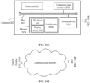
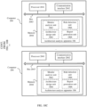
- FIG. 10A, FIG. 10B , and FIG. 10C provide a computer system.
- the computer system is used in the foregoing second deployment manner described above.
- the computer system includes at least one computer 202 and at least one computer 204.
- the computer 204 and the computer 202 are connected through a communication network.
- a hardware structure of the computer 202 in FIG. 10A is similar to that in FIG. 9 .
- a difference is that only an I/O driver 102 and a display driver 104 are run in the computer 202 in FIG. 10A .
- a memory 2024 in FIG. 10A stores executable instructions.
- a processor 2021 executes the executable instructions to execute a part executed by the I/O driver 102 and the display driver 104 in the software architecture analysis method provided in FIG. 3 described above.
- the memory 2024 stores executable instructions to run the I/O driver 102 and the display driver 104.
- a display device 2025 of the computer 202 in FIG. 10A may be a display, configured to provide various interfaces to the user.
- the computer 202 may further include various I/O devices for receiving architecture settings.
- a communication interface 2022 of the computer 202 in FIG. 10A is configured to communicate with the computer 204.
- the computer 204 includes a bus 2043, a processor 2041, a communication interface 2042, and a memory 2024.
- the processor 2041, the memory 2044, and the communication interface 2042 communicate with each other by using the bus 2043.
- the communication interface 2042 is configured to communicate with the computer 202, for example, receive an architecture model and an architecture setting that are sent by the I/O driver 102, and send module call information, the architecture setting, and a detection result to the display driver 104 of the computer 202, so that the display driver 104 generates various interfaces and detection results.
- the processor 2041 may be implemented by using a general-purpose CPU, an FPGA, or another programmable logic device.
- the memory 2044 may include a volatile memory or a non-volatile memory.
- the memory 2044 stores executable instructions, and the processor 2041 executes the executable instructions to execute a part executed by the architecture analysis apparatus 106 and the unit thereof in the software architecture analysis method provided in FIG. 3 described above.
- the memory 2044 stores executable instructions to run the architecture analysis apparatus 106 and the unit thereof described above.
- the memory 2044 may further include executable instructions required to run an operating system of the computer 204.
- the operating system may be Linux TM , Unix TM , Windows TM , or the like.
- the computer system in FIG. 10A, FIG. 10B , and FIG. 10C may include one or more computers 204.
- the computer 204 runs all units of the architecture analysis apparatus 106.
- each of the computers 204 runs all the units of the architecture analysis apparatus 106. In this deployment manner, each computer 204 has all functions of the architecture analysis apparatus 106.
- numerous software architecture analysis tasks may be load-balanced to any computer 204, thereby improving an analysis capacity and analysis efficiency of a software architecture analysis system.
- each computer 204 runs some units of the architecture analysis apparatus 106, and the plurality of computers 204 run all the units of the architecture analysis apparatus 106.
- this deployment manner some units are deployed on each computer 204, and there are fewer types of units running on each computer 204, thereby avoiding conflicts between units of different types, and improving an analysis capacity and analysis efficiency of the software architecture analysis system.
- All or some of the foregoing embodiments may be implemented by using software, hardware, firmware, or any combination thereof.
- software is used to implement embodiments, all or some of the embodiments may be implemented in a form of a computer program product.
- the computer program product includes one or more computer instructions. When the computer instructions are loaded and executed on a computer, the procedures or functions according to embodiments of the present invention are all or partially generated.
- the computer may be a general-purpose computer, a dedicated computer, a computer network, or another programmable apparatus.
- the computer instructions may be stored in a computer-readable storage medium or may be transmitted from a computer-readable storage medium to another computer-readable storage medium.
- the computer instructions may be transmitted from a website, computer, server, or data center to another website, computer, server, or data center in a wired (for example, a coaxial cable, an optical fiber, or a digital tenant line) or wireless (for example, infrared, radio, or microwave) manner.
- the computer-readable storage medium may be any usable medium accessible by a computer, or a data storage device, such as a server or a data center, integrating one or more usable media.
- the usable medium may be a magnetic medium (for example, a floppy disk, a hard disk, or a magnetic tape), an optical medium (for example, a DVD), or a semiconductor medium (for example, an SSD).
Landscapes
- Engineering & Computer Science (AREA)
- Theoretical Computer Science (AREA)
- Software Systems (AREA)
- General Engineering & Computer Science (AREA)
- Physics & Mathematics (AREA)
- General Physics & Mathematics (AREA)
- Computer Hardware Design (AREA)
- Quality & Reliability (AREA)
- Stored Programmes (AREA)
Claims (15)
- Computerimplementiertes Verfahren zur Software-Architekturanalyse, umfassend:Importieren (Schritt 402) eines Architekturmodells, wobei das Architekturmodell eine Vielzahl von Modulen umfasst, jedes Modul ein Softwarecode ist, der mit einer bestimmten Funktion eingestellt ist, und jedes Modul mindestens eine Datei umfasst und wobei das Importieren Empfangen, durch eine Kommunikationsschnittstelle eines Computers, des Architekturmodells und Speichern desselben in einem Speicher des Computers umfasst;Analysieren (Schritt 404) von Dateien, die in der Vielzahl von Modulen umfasst sind, um Modulaufrufinformationen zu erlangen, wobei die Modulaufrufinformationen eine Aufrufbeziehung zwischen der Vielzahl von Modulen umfassen;Erlangen einer Architektureinstellung durch Empfangen einer Eingabe durch einen Benutzer, wobei die Architektureinstellung eine Schichtungsregel und eine Aufrufregel umfasst, die Schichtungsregel eingestellte Informationen einer Vielzahl von Schichten und ein Modul, das an jeder der Vielzahl von Schichten umfasst ist, umfasst und die Aufrufregel eine Aufrufregel zwischen Modulen, die sich an unterschiedlichen Schichten befinden, und/oder eine Aufrufregel zwischen Modulen, die an jeder Schicht umfasst sind, umfasst;Angeben (Schritt 408), eine geschichtete Architekturdarstellungsschnittstelle basierend auf der Schichtungsregel und den Modulaufrufinformationen zu erzeugen, wobei in der geschichteten Architekturdarstellungsschnittstelle jedes Modul einem Bereich zugeordnet ist, der einer Schicht, die das Modul umfasst, entspricht; undDetektieren (Schritt 410) der Modulaufrufinformationen basierend auf der Aufrufregel und Anzeigen eines Detektionsergebnisses unter Verwendung der geschichteten Architekturdarstellungsschnittstelle.
- Verfahren nach Anspruch 1, wobei die eingestellten Informationen der Vielzahl von Schichten eine Sequenznummer jeder Schicht umfassen; und in der geschichteten Architekturdarstellungsschnittstelle ein Ort jeder Schicht basierend auf der Sequenznummer der Schicht eingestellt wird.
- Verfahren nach Anspruch 1 oder 2, wobei das Analysieren von Dateien, die in der Vielzahl von Modulen umfasst sind, um Modulaufrufinformationen zu erlangen, Folgendes umfasst:
Zählen einer Anzahl von Malen, dass eine Datei, die in jedem Modul umfasst ist, eine Datei, die in einem anderen Modul umfasst ist, aufruft, um eine Anzahl von Malen von Aufrufen zwischen der Vielzahl von Modulen zu erlangen. - Verfahren nach Anspruch 3, wobei die Anzahl von Malen von Aufrufen zwischen der Vielzahl von Modulen in der geschichteten Architekturdarstellungsschnittstelle angezeigt wird.
- Verfahren nach einem der Ansprüche 1 bis 4, wobei die Aufrufbeziehung zwischen der Vielzahl von Modulen unter Verwendung eines Pfeiles in der geschichteten Architekturdarstellungsschnittstelle angezeigt wird.
- Verfahren nach Anspruch 5, wobei das Anzeigen eines Detektionsergebnisses unter Verwendung der geschichteten Architekturdarstellungsschnittstelle Folgendes umfasst:
Ändern, in der geschichteten Architekturdarstellungsschnittstelle, einer Farbe und/oder eines Formats eines Pfeiles, der einem Aufruf entspricht, der zwischen Modulen ist und der gegen die Aufrufregel verstößt. - Verfahren nach einem der Ansprüche 1 bis 6, wobei die Aufrufregel zwischen Modulen, die sich an verschiedenen Schichten befinden, eine oder mehrere von Folgendem umfasst:
einer Aufrufregel benachbarter Schichten, einer schichtübergreifenden Aufrufregel und einer Rückrufregel. - Verfahren nach einem der Ansprüche 1 bis 7, wobei in der geschichteten Architekturdarstellungsschnittstelle Farben und/oder Texturen von Bereichen, die benachbarten Schichten entsprechen, unterschiedlich sind.
- Software-Architekturanalysevorrichtung (106), umfassend:eine Modulanalyseeinheit (1062), die dazu konfiguriert ist, ein Architekturmodell zu importieren, wobei das Architekturmodell eine Vielzahl von Modulen umfasst, jedes Modul ein Softwarecode ist, der mit einer bestimmten Funktion eingestellt ist, und jedes Modul mindestens eine Datei umfasst und wobei das Importieren Empfangen, durch eine Kommunikationsschnittstelle der Vorrichtung, des Architekturmodells und Speichern desselben in einem Speicher der Vorrichtung umfasst; Dateien, die in der Vielzahl von Modulen umfasst sind, zu analysieren, um Modulaufrufinformationen zu erlangen, wobei die Modulaufrufinformationen eine Aufrufbeziehung zwischen der Vielzahl von Modulen umfassen;eine Architekturentwurfseinheit (1064), die dazu konfiguriert ist, eine Architektureinstellung durch Empfangen einer Eingabe durch einen Benutzer zu erlangen, wobei die Architektureinstellung eine Schichtungsregel und eine Aufrufregel umfasst, die Schichtungsregel eingestellte Informationen einer Vielzahl von Schichten und ein Modul, das an jeder der Vielzahl von Schichten umfasst ist, umfasst und die Aufrufregel eine Aufrufregel zwischen Modulen, die sich an verschiedenen Schichten befinden, und/oder eine Aufrufregel zwischen Modulen, die an jeder Schicht umfasst sind, umfasst;und anzugeben, eine geschichtete Architekturdarstellungsschnittstelle basierend auf der Schichtungsregel und den Modulaufrufinformationen zu erzeugen, wobei in der geschichteten Architekturdarstellungsschnittstelle jedes Modul einem Bereich zugeordnet ist, der einer Schicht, die das Modul umfasst, entspricht; undeine Regeldetektionseinheit (1066), die dazu konfiguriert ist, die Modulaufrufinformationen basierend auf der Aufrufregel zu detektieren und ein Detektionsergebnis unter Verwendung der geschichteten Architekturdarstellungsschnittstelle anzuzeigen.
- Vorrichtung nach Anspruch 9, wobei die eingestellten Informationen der Vielzahl von Schichten eine Sequenznummer jeder Schicht umfassen; und in der geschichteten Architekturdarstellungsschnittstelle ein Ort jeder Schicht basierend auf der Sequenznummer der Schicht eingestellt wird.
- Vorrichtung nach Anspruch 9 oder 10, wobei die Modulanalyseeinheit (1062) ferner dazu konfiguriert ist, eine Anzahl von Malen zu zählen, dass eine Datei, die in jedem Modul umfasst ist, eine Datei, die in einem anderen Modul umfasst ist, aufruft, um eine Anzahl von Malen von Aufrufen zwischen der Vielzahl von Modulen zu erlangen.
- Vorrichtung nach Anspruch 11, wobei die Architekturentwurfseinheit (1064) ferner dazu konfiguriert ist, einem Anzeigetreiber anzugeben, die Anzahl von Malen von Aufrufen zwischen der Vielzahl von Modulen in der geschichteten Architekturdarstellungsschnittstelle anzuzeigen.
- Vorrichtung nach einem der Ansprüche 9 bis 12, wobei die Aufrufbeziehung zwischen der Vielzahl von Modulen unter Verwendung eines Pfeiles in der geschichteten Architekturdarstellungsschnittstelle angezeigt wird.
- Vorrichtung nach Anspruch 13, wobei die Regeldetektionseinheit (1066) ferner dazu konfiguriert ist, dem Anzeigetreiber anzugeben, in der geschichteten Architekturdarstellungsschnittstelle eine Farbe und/oder ein Format eines Pfeiles zu ändern, der einem Aufruf entspricht, der zwischen Modulen ist und der gegen die Aufrufregel verstößt.
- Vorrichtung nach einem der Ansprüche 9 bis 14, wobei die Aufrufregel zwischen Modulen, die sich an verschiedenen Schichten befinden, eine oder mehrere von Folgendem umfasst:
einer Aufrufregel benachbarter Schichten, einer schichtübergreifenden Aufrufregel und einer Rückrufregel.
Applications Claiming Priority (3)
| Application Number | Priority Date | Filing Date | Title |
|---|---|---|---|
| CN201910994945 | 2019-10-18 | ||
| CN201911399723.2A CN111176724B (zh) | 2019-10-18 | 2019-12-30 | 一种软件架构分析的计算机实现方法及其装置 |
| PCT/CN2020/121893 WO2021073637A1 (zh) | 2019-10-18 | 2020-10-19 | 一种软件架构分析的计算机实现方法及其装置 |
Publications (3)
| Publication Number | Publication Date |
|---|---|
| EP4036714A1 EP4036714A1 (de) | 2022-08-03 |
| EP4036714A4 EP4036714A4 (de) | 2022-11-09 |
| EP4036714B1 true EP4036714B1 (de) | 2025-03-26 |
Family
ID=70658468
Family Applications (1)
| Application Number | Title | Priority Date | Filing Date |
|---|---|---|---|
| EP20877281.4A Active EP4036714B1 (de) | 2019-10-18 | 2020-10-19 | Computerimplementiertes verfahren zur software-architekturanalyse und vorrichtung dafür |
Country Status (4)
| Country | Link |
|---|---|
| US (1) | US12190107B2 (de) |
| EP (1) | EP4036714B1 (de) |
| CN (1) | CN111176724B (de) |
| WO (1) | WO2021073637A1 (de) |
Families Citing this family (2)
| Publication number | Priority date | Publication date | Assignee | Title |
|---|---|---|---|---|
| CN111176724B (zh) * | 2019-10-18 | 2022-06-28 | 华为云计算技术有限公司 | 一种软件架构分析的计算机实现方法及其装置 |
| CN114872645B (zh) * | 2022-05-10 | 2023-03-17 | 中国第一汽车股份有限公司 | 一种车载系统应用管理方法、架构、车辆及介质 |
Family Cites Families (19)
| Publication number | Priority date | Publication date | Assignee | Title |
|---|---|---|---|---|
| WO2005029382A2 (en) * | 2003-09-19 | 2005-03-31 | Lattix, Inc. | Apparatus and method for managing design of a software system using dependency structure |
| CN101281466A (zh) * | 2008-05-27 | 2008-10-08 | 北京中企开源信息技术有限公司 | 基于业务本体特征的业务对象建模方法 |
| US20100058288A1 (en) * | 2008-09-03 | 2010-03-04 | Alexander Von Zitzewitz | Method And System for Structuring a Software Implementation |
| US9716632B2 (en) * | 2010-08-24 | 2017-07-25 | Hewlett Packard Enterprise Development Lp | Interactive layered visualization of a layered software architecture |
| CN102722362B (zh) * | 2011-03-31 | 2016-08-17 | 新奥特(北京)视频技术有限公司 | 一种结构化与saam方法结合的软件架构分析设计方法 |
| US20130060824A1 (en) * | 2011-09-01 | 2013-03-07 | Computer Associates Think, Inc. | System for embedded knowledge management |
| US8832662B2 (en) * | 2012-05-08 | 2014-09-09 | Siemens Aktiengesellschaft | Rules engine for architectural governance |
| CN105745620B (zh) * | 2013-12-31 | 2019-04-30 | 北京新媒传信科技有限公司 | 软件架构的实现方法和实现平台 |
| US10503907B2 (en) * | 2015-12-14 | 2019-12-10 | Fmr Llc | Intelligent threat modeling and visualization |
| CN107103244B (zh) * | 2017-05-12 | 2020-04-17 | 天津大学 | 基于AADL的Web应用架构安全性的评估方法 |
| EP3493051A1 (de) * | 2017-11-30 | 2019-06-05 | The MathWorks, Inc. | System und verfahren zur beurteilung der einhaltung des implementierungscodes mit einer softwarearchitekturspezifikation |
| WO2020023476A1 (en) * | 2018-07-23 | 2020-01-30 | Jpmorgan Chase Bank, N.A. | Dynamic visualization of application and infrastructure components with layers |
| CN110858141B (zh) * | 2018-08-23 | 2023-07-28 | 西门子股份公司 | 分层架构软件中代码评估方法、装置及存储介质 |
| CN109492144B (zh) * | 2018-09-26 | 2023-09-15 | 平安科技(深圳)有限公司 | 软件系统的关联关系分析方法、装置和存储介质 |
| CN109491728A (zh) * | 2018-10-25 | 2019-03-19 | 基石酷联微电子技术(北京)有限公司 | 基于有限状态机的软件架构系统 |
| US11194688B1 (en) * | 2019-05-08 | 2021-12-07 | Amazon Technologies, Inc. | Application architecture optimization and visualization |
| CN110221929A (zh) * | 2019-06-19 | 2019-09-10 | 上海缤游网络科技有限公司 | 一种服务化软件系统架构及其应用方法 |
| CN111176724B (zh) | 2019-10-18 | 2022-06-28 | 华为云计算技术有限公司 | 一种软件架构分析的计算机实现方法及其装置 |
| US12328582B2 (en) * | 2021-12-22 | 2025-06-10 | Pra Audio Systems, Inc. | Wireless audio distribution systems and methods |
-
2019
- 2019-12-30 CN CN201911399723.2A patent/CN111176724B/zh active Active
-
2020
- 2020-10-19 WO PCT/CN2020/121893 patent/WO2021073637A1/zh not_active Ceased
- 2020-10-19 EP EP20877281.4A patent/EP4036714B1/de active Active
-
2022
- 2022-04-14 US US17/720,797 patent/US12190107B2/en active Active
Also Published As
| Publication number | Publication date |
|---|---|
| CN111176724A (zh) | 2020-05-19 |
| CN111176724B (zh) | 2022-06-28 |
| EP4036714A1 (de) | 2022-08-03 |
| WO2021073637A1 (zh) | 2021-04-22 |
| US20220236983A1 (en) | 2022-07-28 |
| US12190107B2 (en) | 2025-01-07 |
| EP4036714A4 (de) | 2022-11-09 |
Similar Documents
| Publication | Publication Date | Title |
|---|---|---|
| US11269905B2 (en) | Interaction between visualizations and other data controls in an information system by matching attributes in different datasets | |
| US10481875B2 (en) | Generation of an application from template | |
| US9696967B2 (en) | Generation of an application from data | |
| US8966440B2 (en) | Custom application creation in multi-tenant systems | |
| WO2020253059A1 (zh) | 多级联动下拉框的实现方法、装置和计算机设备 | |
| CN109308284B (zh) | 报表菜单生成方法、装置、计算机设备及存储介质 | |
| US9753700B2 (en) | Application building blocks for on demand and on premise usage | |
| KR20140041452A (ko) | 전자 문서를 검색하는 방법 및 전자 문서 검색을 그래픽적으로 나타내는 방법 | |
| US8566740B2 (en) | Interactive data forecasting features for a graphical user interface | |
| US9451033B2 (en) | Enhanced command selection in a networked computing environment | |
| US20120144313A1 (en) | Filtering objects in a multi-tenant environment | |
| US9225662B2 (en) | Command management in a networked computing environment | |
| US20130055118A1 (en) | Configuring database objects in multi-tenant systems | |
| EP4036714B1 (de) | Computerimplementiertes verfahren zur software-architekturanalyse und vorrichtung dafür | |
| US8713152B2 (en) | Managing distributed applications using structural diagrams | |
| EP4348467B1 (de) | Standardisierung und rationalisierung der bereitstellung von sicherheitsinformationen | |
| CN112579664A (zh) | 图表联动的处理方法和装置 | |
| US9189544B2 (en) | Graphically representing tags in a networked computing environment | |
| US12373497B1 (en) | Dynamic generation of performance state tree | |
| US20240220237A1 (en) | Smart grouping of code packages | |
| US20190391902A1 (en) | Visualizing a user-centric stack frame graph | |
| US11120058B2 (en) | Generating and providing stacked attribution breakdowns within a stacked attribution interface by applying attribution models to dimensions of a digital content campaign | |
| US20260086696A1 (en) | System and method for generating dynamic layouts in a complex computing network | |
| US20260023788A1 (en) | Dynamic generation of performance state tree | |
| US20230177090A1 (en) | Systems, methods, and devices for dynamic record filter criteria for data objects of computing platforms |
Legal Events
| Date | Code | Title | Description |
|---|---|---|---|
| STAA | Information on the status of an ep patent application or granted ep patent |
Free format text: STATUS: THE INTERNATIONAL PUBLICATION HAS BEEN MADE |
|
| PUAI | Public reference made under article 153(3) epc to a published international application that has entered the european phase |
Free format text: ORIGINAL CODE: 0009012 |
|
| STAA | Information on the status of an ep patent application or granted ep patent |
Free format text: STATUS: REQUEST FOR EXAMINATION WAS MADE |
|
| 17P | Request for examination filed |
Effective date: 20220428 |
|
| AK | Designated contracting states |
Kind code of ref document: A1 Designated state(s): AL AT BE BG CH CY CZ DE DK EE ES FI FR GB GR HR HU IE IS IT LI LT LU LV MC MK MT NL NO PL PT RO RS SE SI SK SM TR |
|
| A4 | Supplementary search report drawn up and despatched |
Effective date: 20221007 |
|
| RIC1 | Information provided on ipc code assigned before grant |
Ipc: G06F 11/36 20060101ALN20220930BHEP Ipc: G06F 11/32 20060101ALN20220930BHEP Ipc: G06F 8/20 20180101ALI20220930BHEP Ipc: G06F 8/75 20180101AFI20220930BHEP |
|
| DAV | Request for validation of the european patent (deleted) | ||
| DAX | Request for extension of the european patent (deleted) | ||
| STAA | Information on the status of an ep patent application or granted ep patent |
Free format text: STATUS: EXAMINATION IS IN PROGRESS |
|
| 17Q | First examination report despatched |
Effective date: 20240603 |
|
| GRAP | Despatch of communication of intention to grant a patent |
Free format text: ORIGINAL CODE: EPIDOSNIGR1 |
|
| STAA | Information on the status of an ep patent application or granted ep patent |
Free format text: STATUS: GRANT OF PATENT IS INTENDED |
|
| RIC1 | Information provided on ipc code assigned before grant |
Ipc: G06F 11/36 20060101ALI20241028BHEP Ipc: G06F 8/20 20180101ALI20241028BHEP Ipc: G06F 8/75 20180101AFI20241028BHEP |
|
| INTG | Intention to grant announced |
Effective date: 20241107 |
|
| GRAS | Grant fee paid |
Free format text: ORIGINAL CODE: EPIDOSNIGR3 |
|
| GRAA | (expected) grant |
Free format text: ORIGINAL CODE: 0009210 |
|
| STAA | Information on the status of an ep patent application or granted ep patent |
Free format text: STATUS: THE PATENT HAS BEEN GRANTED |
|
| P01 | Opt-out of the competence of the unified patent court (upc) registered |
Free format text: CASE NUMBER: APP_4433/2025 Effective date: 20250127 |
|
| AK | Designated contracting states |
Kind code of ref document: B1 Designated state(s): AL AT BE BG CH CY CZ DE DK EE ES FI FR GB GR HR HU IE IS IT LI LT LU LV MC MK MT NL NO PL PT RO RS SE SI SK SM TR |
|
| REG | Reference to a national code |
Ref country code: GB Ref legal event code: FG4D |
|
| REG | Reference to a national code |
Ref country code: CH Ref legal event code: EP |
|
| REG | Reference to a national code |
Ref country code: DE Ref legal event code: R096 Ref document number: 602020048503 Country of ref document: DE |
|
| REG | Reference to a national code |
Ref country code: IE Ref legal event code: FG4D |
|
| PG25 | Lapsed in a contracting state [announced via postgrant information from national office to epo] |
Ref country code: RS Free format text: LAPSE BECAUSE OF FAILURE TO SUBMIT A TRANSLATION OF THE DESCRIPTION OR TO PAY THE FEE WITHIN THE PRESCRIBED TIME-LIMIT Effective date: 20250626 |
|
| PG25 | Lapsed in a contracting state [announced via postgrant information from national office to epo] |
Ref country code: FI Free format text: LAPSE BECAUSE OF FAILURE TO SUBMIT A TRANSLATION OF THE DESCRIPTION OR TO PAY THE FEE WITHIN THE PRESCRIBED TIME-LIMIT Effective date: 20250326 |
|
| REG | Reference to a national code |
Ref country code: LT Ref legal event code: MG9D |
|
| PG25 | Lapsed in a contracting state [announced via postgrant information from national office to epo] |
Ref country code: NO Free format text: LAPSE BECAUSE OF FAILURE TO SUBMIT A TRANSLATION OF THE DESCRIPTION OR TO PAY THE FEE WITHIN THE PRESCRIBED TIME-LIMIT Effective date: 20250626 |
|
| PG25 | Lapsed in a contracting state [announced via postgrant information from national office to epo] |
Ref country code: HR Free format text: LAPSE BECAUSE OF FAILURE TO SUBMIT A TRANSLATION OF THE DESCRIPTION OR TO PAY THE FEE WITHIN THE PRESCRIBED TIME-LIMIT Effective date: 20250326 |
|
| PG25 | Lapsed in a contracting state [announced via postgrant information from national office to epo] |
Ref country code: LV Free format text: LAPSE BECAUSE OF FAILURE TO SUBMIT A TRANSLATION OF THE DESCRIPTION OR TO PAY THE FEE WITHIN THE PRESCRIBED TIME-LIMIT Effective date: 20250326 |
|
| PG25 | Lapsed in a contracting state [announced via postgrant information from national office to epo] |
Ref country code: BG Free format text: LAPSE BECAUSE OF FAILURE TO SUBMIT A TRANSLATION OF THE DESCRIPTION OR TO PAY THE FEE WITHIN THE PRESCRIBED TIME-LIMIT Effective date: 20250326 Ref country code: GR Free format text: LAPSE BECAUSE OF FAILURE TO SUBMIT A TRANSLATION OF THE DESCRIPTION OR TO PAY THE FEE WITHIN THE PRESCRIBED TIME-LIMIT Effective date: 20250627 |
|
| REG | Reference to a national code |
Ref country code: NL Ref legal event code: MP Effective date: 20250326 |
|
| PG25 | Lapsed in a contracting state [announced via postgrant information from national office to epo] |
Ref country code: NL Free format text: LAPSE BECAUSE OF FAILURE TO SUBMIT A TRANSLATION OF THE DESCRIPTION OR TO PAY THE FEE WITHIN THE PRESCRIBED TIME-LIMIT Effective date: 20250326 |
|
| PG25 | Lapsed in a contracting state [announced via postgrant information from national office to epo] |
Ref country code: SE Free format text: LAPSE BECAUSE OF FAILURE TO SUBMIT A TRANSLATION OF THE DESCRIPTION OR TO PAY THE FEE WITHIN THE PRESCRIBED TIME-LIMIT Effective date: 20250326 |
|
| REG | Reference to a national code |
Ref country code: AT Ref legal event code: MK05 Ref document number: 1779591 Country of ref document: AT Kind code of ref document: T Effective date: 20250326 |
|
| PG25 | Lapsed in a contracting state [announced via postgrant information from national office to epo] |
Ref country code: SM Free format text: LAPSE BECAUSE OF FAILURE TO SUBMIT A TRANSLATION OF THE DESCRIPTION OR TO PAY THE FEE WITHIN THE PRESCRIBED TIME-LIMIT Effective date: 20250326 |
|
| PG25 | Lapsed in a contracting state [announced via postgrant information from national office to epo] |
Ref country code: PT Free format text: LAPSE BECAUSE OF FAILURE TO SUBMIT A TRANSLATION OF THE DESCRIPTION OR TO PAY THE FEE WITHIN THE PRESCRIBED TIME-LIMIT Effective date: 20250728 Ref country code: ES Free format text: LAPSE BECAUSE OF FAILURE TO SUBMIT A TRANSLATION OF THE DESCRIPTION OR TO PAY THE FEE WITHIN THE PRESCRIBED TIME-LIMIT Effective date: 20250326 |
|
| PG25 | Lapsed in a contracting state [announced via postgrant information from national office to epo] |
Ref country code: IT Free format text: LAPSE BECAUSE OF FAILURE TO SUBMIT A TRANSLATION OF THE DESCRIPTION OR TO PAY THE FEE WITHIN THE PRESCRIBED TIME-LIMIT Effective date: 20250326 Ref country code: PL Free format text: LAPSE BECAUSE OF FAILURE TO SUBMIT A TRANSLATION OF THE DESCRIPTION OR TO PAY THE FEE WITHIN THE PRESCRIBED TIME-LIMIT Effective date: 20250326 |
|
| PG25 | Lapsed in a contracting state [announced via postgrant information from national office to epo] |
Ref country code: AT Free format text: LAPSE BECAUSE OF FAILURE TO SUBMIT A TRANSLATION OF THE DESCRIPTION OR TO PAY THE FEE WITHIN THE PRESCRIBED TIME-LIMIT Effective date: 20250326 |
|
| PGFP | Annual fee paid to national office [announced via postgrant information from national office to epo] |
Ref country code: FR Payment date: 20250908 Year of fee payment: 6 |
|
| PG25 | Lapsed in a contracting state [announced via postgrant information from national office to epo] |
Ref country code: EE Free format text: LAPSE BECAUSE OF FAILURE TO SUBMIT A TRANSLATION OF THE DESCRIPTION OR TO PAY THE FEE WITHIN THE PRESCRIBED TIME-LIMIT Effective date: 20250326 |
|
| PGFP | Annual fee paid to national office [announced via postgrant information from national office to epo] |
Ref country code: IE Payment date: 20250909 Year of fee payment: 6 |
|
| PG25 | Lapsed in a contracting state [announced via postgrant information from national office to epo] |
Ref country code: RO Free format text: LAPSE BECAUSE OF FAILURE TO SUBMIT A TRANSLATION OF THE DESCRIPTION OR TO PAY THE FEE WITHIN THE PRESCRIBED TIME-LIMIT Effective date: 20250326 |
|
| PG25 | Lapsed in a contracting state [announced via postgrant information from national office to epo] |
Ref country code: SK Free format text: LAPSE BECAUSE OF FAILURE TO SUBMIT A TRANSLATION OF THE DESCRIPTION OR TO PAY THE FEE WITHIN THE PRESCRIBED TIME-LIMIT Effective date: 20250326 |
|
| PG25 | Lapsed in a contracting state [announced via postgrant information from national office to epo] |
Ref country code: IS Free format text: LAPSE BECAUSE OF FAILURE TO SUBMIT A TRANSLATION OF THE DESCRIPTION OR TO PAY THE FEE WITHIN THE PRESCRIBED TIME-LIMIT Effective date: 20250726 |
|
| REG | Reference to a national code |
Ref country code: DE Ref legal event code: R097 Ref document number: 602020048503 Country of ref document: DE |
|
| PGFP | Annual fee paid to national office [announced via postgrant information from national office to epo] |
Ref country code: DE Payment date: 20250902 Year of fee payment: 6 |
|
| PG25 | Lapsed in a contracting state [announced via postgrant information from national office to epo] |
Ref country code: DK Free format text: LAPSE BECAUSE OF FAILURE TO SUBMIT A TRANSLATION OF THE DESCRIPTION OR TO PAY THE FEE WITHIN THE PRESCRIBED TIME-LIMIT Effective date: 20250326 |
|
| PG25 | Lapsed in a contracting state [announced via postgrant information from national office to epo] |
Ref country code: CZ Free format text: LAPSE BECAUSE OF FAILURE TO SUBMIT A TRANSLATION OF THE DESCRIPTION OR TO PAY THE FEE WITHIN THE PRESCRIBED TIME-LIMIT Effective date: 20250326 |
|
| PLBE | No opposition filed within time limit |
Free format text: ORIGINAL CODE: 0009261 |
|
| STAA | Information on the status of an ep patent application or granted ep patent |
Free format text: STATUS: NO OPPOSITION FILED WITHIN TIME LIMIT |
|
| REG | Reference to a national code |
Ref country code: CH Ref legal event code: L10 Free format text: ST27 STATUS EVENT CODE: U-0-0-L10-L00 (AS PROVIDED BY THE NATIONAL OFFICE) Effective date: 20260211 |
|
| 26N | No opposition filed |
Effective date: 20260105 |