EP4036640B1 - Pdlc film electrode manufacturing method - Google Patents
Pdlc film electrode manufacturing method Download PDFInfo
- Publication number
- EP4036640B1 EP4036640B1 EP21865359.0A EP21865359A EP4036640B1 EP 4036640 B1 EP4036640 B1 EP 4036640B1 EP 21865359 A EP21865359 A EP 21865359A EP 4036640 B1 EP4036640 B1 EP 4036640B1
- Authority
- EP
- European Patent Office
- Prior art keywords
- liquid crystal
- area
- membrane
- pdlc
- negative pressure
- Prior art date
- Legal status (The legal status is an assumption and is not a legal conclusion. Google has not performed a legal analysis and makes no representation as to the accuracy of the status listed.)
- Active
Links
Images
Classifications
-
- G—PHYSICS
- G02—OPTICS
- G02F—OPTICAL DEVICES OR ARRANGEMENTS FOR THE CONTROL OF LIGHT BY MODIFICATION OF THE OPTICAL PROPERTIES OF THE MEDIA OF THE ELEMENTS INVOLVED THEREIN; NON-LINEAR OPTICS; FREQUENCY-CHANGING OF LIGHT; OPTICAL LOGIC ELEMENTS; OPTICAL ANALOGUE/DIGITAL CONVERTERS
- G02F1/00—Devices or arrangements for the control of the intensity, colour, phase, polarisation or direction of light arriving from an independent light source, e.g. switching, gating or modulating; Non-linear optics
- G02F1/01—Devices or arrangements for the control of the intensity, colour, phase, polarisation or direction of light arriving from an independent light source, e.g. switching, gating or modulating; Non-linear optics for the control of the intensity, phase, polarisation or colour
- G02F1/13—Devices or arrangements for the control of the intensity, colour, phase, polarisation or direction of light arriving from an independent light source, e.g. switching, gating or modulating; Non-linear optics for the control of the intensity, phase, polarisation or colour based on liquid crystals, e.g. single liquid crystal display cells
- G02F1/133—Constructional arrangements; Operation of liquid crystal cells; Circuit arrangements
- G02F1/1333—Constructional arrangements; Manufacturing methods
- G02F1/1343—Electrodes
- G02F1/13439—Electrodes characterised by their electrical, optical, physical properties; materials therefor; method of making
-
- B—PERFORMING OPERATIONS; TRANSPORTING
- B23—MACHINE TOOLS; METAL-WORKING NOT OTHERWISE PROVIDED FOR
- B23K—SOLDERING OR UNSOLDERING; WELDING; CLADDING OR PLATING BY SOLDERING OR WELDING; CUTTING BY APPLYING HEAT LOCALLY, e.g. FLAME CUTTING; WORKING BY LASER BEAM
- B23K26/00—Working by laser beam, e.g. welding, cutting or boring
- B23K26/50—Working by transmitting the laser beam through or within the workpiece
-
- G—PHYSICS
- G02—OPTICS
- G02F—OPTICAL DEVICES OR ARRANGEMENTS FOR THE CONTROL OF LIGHT BY MODIFICATION OF THE OPTICAL PROPERTIES OF THE MEDIA OF THE ELEMENTS INVOLVED THEREIN; NON-LINEAR OPTICS; FREQUENCY-CHANGING OF LIGHT; OPTICAL LOGIC ELEMENTS; OPTICAL ANALOGUE/DIGITAL CONVERTERS
- G02F1/00—Devices or arrangements for the control of the intensity, colour, phase, polarisation or direction of light arriving from an independent light source, e.g. switching, gating or modulating; Non-linear optics
- G02F1/01—Devices or arrangements for the control of the intensity, colour, phase, polarisation or direction of light arriving from an independent light source, e.g. switching, gating or modulating; Non-linear optics for the control of the intensity, phase, polarisation or colour
- G02F1/13—Devices or arrangements for the control of the intensity, colour, phase, polarisation or direction of light arriving from an independent light source, e.g. switching, gating or modulating; Non-linear optics for the control of the intensity, phase, polarisation or colour based on liquid crystals, e.g. single liquid crystal display cells
- G02F1/1303—Apparatus specially adapted to the manufacture of LCDs
-
- G—PHYSICS
- G02—OPTICS
- G02F—OPTICAL DEVICES OR ARRANGEMENTS FOR THE CONTROL OF LIGHT BY MODIFICATION OF THE OPTICAL PROPERTIES OF THE MEDIA OF THE ELEMENTS INVOLVED THEREIN; NON-LINEAR OPTICS; FREQUENCY-CHANGING OF LIGHT; OPTICAL LOGIC ELEMENTS; OPTICAL ANALOGUE/DIGITAL CONVERTERS
- G02F1/00—Devices or arrangements for the control of the intensity, colour, phase, polarisation or direction of light arriving from an independent light source, e.g. switching, gating or modulating; Non-linear optics
- G02F1/01—Devices or arrangements for the control of the intensity, colour, phase, polarisation or direction of light arriving from an independent light source, e.g. switching, gating or modulating; Non-linear optics for the control of the intensity, phase, polarisation or colour
- G02F1/13—Devices or arrangements for the control of the intensity, colour, phase, polarisation or direction of light arriving from an independent light source, e.g. switching, gating or modulating; Non-linear optics for the control of the intensity, phase, polarisation or colour based on liquid crystals, e.g. single liquid crystal display cells
- G02F1/133—Constructional arrangements; Operation of liquid crystal cells; Circuit arrangements
- G02F1/1333—Constructional arrangements; Manufacturing methods
-
- G—PHYSICS
- G02—OPTICS
- G02F—OPTICAL DEVICES OR ARRANGEMENTS FOR THE CONTROL OF LIGHT BY MODIFICATION OF THE OPTICAL PROPERTIES OF THE MEDIA OF THE ELEMENTS INVOLVED THEREIN; NON-LINEAR OPTICS; FREQUENCY-CHANGING OF LIGHT; OPTICAL LOGIC ELEMENTS; OPTICAL ANALOGUE/DIGITAL CONVERTERS
- G02F1/00—Devices or arrangements for the control of the intensity, colour, phase, polarisation or direction of light arriving from an independent light source, e.g. switching, gating or modulating; Non-linear optics
- G02F1/01—Devices or arrangements for the control of the intensity, colour, phase, polarisation or direction of light arriving from an independent light source, e.g. switching, gating or modulating; Non-linear optics for the control of the intensity, phase, polarisation or colour
- G02F1/13—Devices or arrangements for the control of the intensity, colour, phase, polarisation or direction of light arriving from an independent light source, e.g. switching, gating or modulating; Non-linear optics for the control of the intensity, phase, polarisation or colour based on liquid crystals, e.g. single liquid crystal display cells
- G02F1/133—Constructional arrangements; Operation of liquid crystal cells; Circuit arrangements
- G02F1/1333—Constructional arrangements; Manufacturing methods
- G02F1/1334—Constructional arrangements; Manufacturing methods based on polymer dispersed liquid crystals, e.g. microencapsulated liquid crystals
-
- G—PHYSICS
- G02—OPTICS
- G02F—OPTICAL DEVICES OR ARRANGEMENTS FOR THE CONTROL OF LIGHT BY MODIFICATION OF THE OPTICAL PROPERTIES OF THE MEDIA OF THE ELEMENTS INVOLVED THEREIN; NON-LINEAR OPTICS; FREQUENCY-CHANGING OF LIGHT; OPTICAL LOGIC ELEMENTS; OPTICAL ANALOGUE/DIGITAL CONVERTERS
- G02F1/00—Devices or arrangements for the control of the intensity, colour, phase, polarisation or direction of light arriving from an independent light source, e.g. switching, gating or modulating; Non-linear optics
- G02F1/01—Devices or arrangements for the control of the intensity, colour, phase, polarisation or direction of light arriving from an independent light source, e.g. switching, gating or modulating; Non-linear optics for the control of the intensity, phase, polarisation or colour
- G02F1/13—Devices or arrangements for the control of the intensity, colour, phase, polarisation or direction of light arriving from an independent light source, e.g. switching, gating or modulating; Non-linear optics for the control of the intensity, phase, polarisation or colour based on liquid crystals, e.g. single liquid crystal display cells
- G02F1/133—Constructional arrangements; Operation of liquid crystal cells; Circuit arrangements
- G02F1/1333—Constructional arrangements; Manufacturing methods
- G02F1/1343—Electrodes
-
- G—PHYSICS
- G02—OPTICS
- G02F—OPTICAL DEVICES OR ARRANGEMENTS FOR THE CONTROL OF LIGHT BY MODIFICATION OF THE OPTICAL PROPERTIES OF THE MEDIA OF THE ELEMENTS INVOLVED THEREIN; NON-LINEAR OPTICS; FREQUENCY-CHANGING OF LIGHT; OPTICAL LOGIC ELEMENTS; OPTICAL ANALOGUE/DIGITAL CONVERTERS
- G02F1/00—Devices or arrangements for the control of the intensity, colour, phase, polarisation or direction of light arriving from an independent light source, e.g. switching, gating or modulating; Non-linear optics
- G02F1/01—Devices or arrangements for the control of the intensity, colour, phase, polarisation or direction of light arriving from an independent light source, e.g. switching, gating or modulating; Non-linear optics for the control of the intensity, phase, polarisation or colour
- G02F1/13—Devices or arrangements for the control of the intensity, colour, phase, polarisation or direction of light arriving from an independent light source, e.g. switching, gating or modulating; Non-linear optics for the control of the intensity, phase, polarisation or colour based on liquid crystals, e.g. single liquid crystal display cells
- G02F1/133—Constructional arrangements; Operation of liquid crystal cells; Circuit arrangements
- G02F1/1333—Constructional arrangements; Manufacturing methods
- G02F1/1345—Conductors connecting electrodes to cell terminals
- G02F1/13452—Conductors connecting driver circuitry and terminals of panels
-
- G—PHYSICS
- G02—OPTICS
- G02F—OPTICAL DEVICES OR ARRANGEMENTS FOR THE CONTROL OF LIGHT BY MODIFICATION OF THE OPTICAL PROPERTIES OF THE MEDIA OF THE ELEMENTS INVOLVED THEREIN; NON-LINEAR OPTICS; FREQUENCY-CHANGING OF LIGHT; OPTICAL LOGIC ELEMENTS; OPTICAL ANALOGUE/DIGITAL CONVERTERS
- G02F1/00—Devices or arrangements for the control of the intensity, colour, phase, polarisation or direction of light arriving from an independent light source, e.g. switching, gating or modulating; Non-linear optics
- G02F1/01—Devices or arrangements for the control of the intensity, colour, phase, polarisation or direction of light arriving from an independent light source, e.g. switching, gating or modulating; Non-linear optics for the control of the intensity, phase, polarisation or colour
- G02F1/13—Devices or arrangements for the control of the intensity, colour, phase, polarisation or direction of light arriving from an independent light source, e.g. switching, gating or modulating; Non-linear optics for the control of the intensity, phase, polarisation or colour based on liquid crystals, e.g. single liquid crystal display cells
- G02F1/133—Constructional arrangements; Operation of liquid crystal cells; Circuit arrangements
- G02F1/1333—Constructional arrangements; Manufacturing methods
- G02F1/1345—Conductors connecting electrodes to cell terminals
- G02F1/13458—Terminal pads
Definitions
- the present invention relates to the technical field of electrode processing, and in particular, to a method for manufacturing a PDLC membrane electrode, a negative pressure platform and a PDLC membrane.
- PDLC Polymer Dispersed Liquid Crystal
- PDLC Polymer Dispersed Liquid Crystal
- PDLC is a new type of optoelectronic film material, that is, liquid crystal is dispersed in a polymer, and the formed liquid crystal droplets, under certain conditions, are uniformly dispersed in a continuous polymer matrix through polymerization reaction. Due to the optical anisotropy and dielectric anisotropy of liquid crystal molecules, PDLC becomes a composite material with electro-optical response characteristics.
- the production of a PDLC membrane electrode is one of the core processes, and its main function is to connect and energize the conductive films on both sides of the PDLC membrane, so as to deflect the liquid crystal.
- the quality of electrode production directly lead to whether the membrane can be driven normally, whether it is fully driven, and whether there is breakdown or short circuit near the electrode.
- the electrode production process of PDLC membranes on the market comprises: manually cutting into sheets, dividing PDLC membrane electrodes, and erasing PDLC adhesive layer with alcohol, etc., which are basically manual operations.
- one sheet with a size of 5000mm ⁇ 1500mm ⁇ 500mm requires the workload of one worker working for five hours, resulting in low work efficiency and low precision; alternatively, it is processed by semiautomatic equipment and then spliced manually, leading to the relatively low yield of the electrode production and the relatively low efficiency.
- WO2020071110A1 provides a method of manufacturing a dimming element which is capable of forming an extraction electrode part without damaging a transparent electrode layer or causing problems in the work environment.
- This method of manufacturing a dimming element includes: removing, from a predetermined portion of a dimming film that has a first substrate with a transparent electrode layer and a second substrate with a transparent electrode layer, which are arranged so that the transparent electrode layers face one another, and a liquid crystal dimming layer that is sandwiched between the substrates with the transparent electrode layers, one of the substrates with the transparent electrode layers; using an organic solvent to cause the liquid crystal dimming layer that remains in the predetermined portion after the one of the substrates with the transparent electrode layers is removed to swell; attaching an adhesive tape to a surface of the swollen liquid crystal dimming layer; and peeling the adhesive tape together with the swollen liquid crystal dimming layer away from the dimming film.
- WO2020054445A1 provides a method for obtaining a dimming element that has a lead-out electrode without breaking a transparent electrode layer that is the transparent electrode layer used as a lead-out electrode.
- This method for manufacturing a dimming element that has a lead-out electrode comprises: a step of obtaining a dimming film (100) that includes a first transparent electrode layer-attached base material (10) and a second transparent electrode layer-attached base material (20) which are arranged so that the transparent electrode layers face each other and a liquid crystal dimming layer (30) interposed between the transparent electrode layer-attached base materials, the dimming film further including an extended section that extends in a direction perpendicular to the thickness direction; a step of peeling one transparent electrode layer-attached base material (20) from the dimming film (100) by inserting a peeling means (200) between the transparent electrode layer-attached base materials at the extended section; and a step of bending the peeled portion of the one transparent electrode
- JP4655406B2 provides a suction plate of the upper surface of the suction table is so constituted that multiple transparent columns having the parallel upper surfaces and lower surfaces are aligned into a plate shape and a light is irradiated from a plane emitting body provided in the lower part of the suction plate.
- the display element is peeled off from the UV-transmitting film as adhesive strength of the adhesive applied to the UV-transmitting film is dissipated by ultraviolet rays irradiated by the UV lamp, and simultaneously, the display element is bonded as a soldering print is instantly melted by the laser irradiated by the laser irradiator, so that a transfer operation is performed in a very simple, rapid, and stable way.
- the present invention provides a method for manufacturing a PDLC membrane electrode, in which the contents of the method is the same as the pending claims.
- orientation or positional relationship indicated by the terms such as “center”, “upper”, “lower”, “left”, “right”, “vertical”, “horizontal”, “inner”, “outer”, “front side”, “back side”, is based on the orientation or positional relationship shown in the drawings, or the orientation or positional relationship when the product of the invention is usually placed in use, and it is only for the convenience of describing the present invention and simplifying the description, rather than indicating or implying that the indicated device or element must be of the specific orientation, or be configured and operated in the specific orientation, and therefore cannot be understood as a limitation to the present invention.
- the terms “first”, “second”, “third”, etc. are only used for describing the distinguishing, and cannot be understood as indicating or implying the importance of the relativity.
- Negative pressure refers to any suitable negative pressure that allows the PDLC membrane to be processed to be adsorbed onto the platform so that it remains flat and does not warp.
- the size and shape of the negative pressure platform can be set according to the PDLC membrane to be processed and the desired product.
- the negative pressure platform can be of various possible shapes.
- the negative pressure platform in the present invention comprises a transparent area.
- transparent area refers to an area made of transparent material.
- the transparent material can allow laser light to transmit therethrough, thereby minimizing the absorption and reflection for laser light.
- the main body area of the negative pressure platform is usually a metal material area, taking into account the characteristics of low wear and long service life of the metal material, but any other suitable material may also be used, and for example, it is a transparent material as well.
- the negative pressure platform in the present invention comprises a negative pressure bonding area.
- liquid crystal activation area refers to the area of the PDLC membrane where the liquid crystal layer needs to be activated.
- the transparent area of the negative pressure platform is adapted to the "liquid crystal activation area”.
- other area refers to the area of the PDLC membrane other than the “liquid crystal activation area”.
- the “other area” is adapted to the main body area of the negative pressure platform (for example, the metal material area).
- the “other area” may also be referred to as "non-liquid crystal activation area”.
- half-cut area refers to an area on the negative pressure platform, used to guide where to cut and tear off the PDLC membrane.
- the half-cut area on the negative pressure platform may be located more inwardly than the transparent area, or may coincide with the inner-side boundary of the transparent area.
- the sizes and shapes of the half-cut area and the transparent area on the negative pressure platform can all be changed in any appropriate way, as needed.
- This embodiment provides a method for manufacturing a PDLC membrane electrode.
- the method for manufacturing a PDLC membrane electrode comprises the following steps:
- the PDLC membrane is placed on the negative pressure platform 600 with the back side facing upwards, and the back side liquid crystal activation area of the PDLC membrane is made to coincide with the second transparent area 620 of the negative pressure platform 600, and other areas coincide with the metal material area of the negative pressure platform 600.
- the liquid crystal layer 300 of the PDLC membrane (the back side liquid crystal activation area) is activated.
- the second PET layer 500 and the second electric conduction layer 400 located on the liquid crystal layer 300 are cut and torn off.
- the activated liquid crystal layer 300 is swept off to expose the first electric conduction layer 200 to form a second electrode.
- an infrared laser is used for activation.
- the infrared laser when used for activation, can use the following parameters, wherein
- a carbon dioxide laser is used for cutting.
- the carbon dioxide laser when a carbon dioxide laser is used for cutting, can use the following parameters, wherein
- FIGS. 2 and 3 only exemplarily show the negative pressure platform in the case of activating the side part of the PDLC membrane, where the first transparent area and the second transparent area can be arranged in different ways, such as having different sizes and shapes.
- the front and back sides of the PDLC membrane can be processed in different sizes and shapes, and the processing parameters can also be set differently.
- the terms "front side” and "back side” are only used to distinguish two opposite surfaces of the PDLC membrane, and do not indicate a specific order, structure or the like.
- the activated liquid crystal layer 300 has basically separated from the first electric conduction layer 200 and the second electric conduction layer 400. After the first PET layer 100 and the first electric conduction layer 200 are torn off, a part of the liquid crystal layer 300 can be taken away, and a part of the liquid crystal layer 300 remains in the second electric conduction layer 400. It is possible to use a brush, dust-free cloth or technical foam, etc., to sweep off the remaining part of liquid crystal layer 300, exposing the second electric conduction layer 400, to form the first electrode. Similarly, the same operation can be used for the back side processing steps, which will not be repeated here. However, if the liquid crystal is not activated, the manual wiping, using e.g. alcohol, is required to wipe off the liquid crystal layer 300, which is not only inefficient, but also possible of having the problems, such as incomplete wiping or excessive wiping, which affects the performance of the electrode.
- the manual wiping using e.g. alcohol
- the liquid crystal activation area of the side to be processed of the PDLC membrane coincides with the transparent area 630 of the negative pressure platform 600, and other areas coincide with the metal material area of the negative pressure platform 600.
- the laser light can be made to only penetrate to the transparent area of the negative pressure platform, and not touch the main body area of the negative pressure platform (for example, the metal material area). Since laser light absorbed and reflected by the transparent area is relatively small, a better liquid crystal activation effect is achieved, which is beneficial to the removal of the liquid crystal layer.
- the method for manufacturing a PDLC membrane electrode can reduce the participation by human, increasing the production output, and improving the production efficiency.
- the electrode can be made according to any pattern.
- This embodiment also provides a method for manufacturing a PDLC membrane electrode.
- the method for manufacturing a PDLC membrane electrode comprises the following steps:
- the method for manufacturing a PDLC membrane electrode includes a front side processing step and a back side processing step.
- the PDLC membrane is placed on the negative pressure platform 600 with the front side facing upwards, and the front side liquid crystal activation area of the PDLC membrane is made to coincide with the first transparent area 610 of the negative pressure platform 600, and the other areas coincide with the main body area 640 of the negative pressure platform 600; the liquid crystal layer 300 of the front side liquid crystal activation area of the PDLC membrane is activated; the first PET layer 100 and the first electric conduction layer 200 located on the liquid crystal layer 300 are cut according to the front side half-cut area 10, and the first PET layer 100, the first electric conduction layer 200, and the activated liquid crystal layer 300 are together torn off to expose the second electric conduction layer 400 to form a first electrode.
- the PDLC membrane is placed on the negative pressure platform 600 with the back side facing upwards, and the back side liquid crystal activation area of the PDLC membrane is made to coincide with the second transparent area 620 of the negative pressure platform 600, and other areas coincide with the main body area 640 of the negative pressure platform 600; the liquid crystal layer 300 in the back side liquid crystal activation area of the PDLC membrane is activated; according to the back side half-cut area 20, the second PET layer 500 and the second electric conduction layer 400 located on the liquid crystal layer 300 are cut, and the second PET layer 500, the second electric conduction layer 400 and the activated liquid crystal layer 300 are torn off together to expose the first electric conduction layer 200 to form a second electrode.
- the main body area 640 of the negative pressure platform 600 is a metal material area.
- the negative pressure platform 600 may include a plurality of vent holes 650.
- the main body area 640 of the negative pressure platform comprises a plurality of vent holes 650.
- the transparent area 630 of the negative pressure platform comprises a plurality of vent holes 650.
- both the main body area 640 and the transparent area 630 of the negative pressure platform include a plurality of vent holes 650.
- Each vent hole 650 is in fluid communication with a vacuum device (for example, a vacuum pump) 700.
- the vent hole 650 has a diameter of 0.5 to 3.0 mm, 0.8 to 2.5 mm, or 1 to 2 mm.
- the hole spacing between adjacent vent holes 650 is 10-50 mm, 15-40 mm, or 20-30 mm.
- a valve 710 (such as a solenoid valve) is provided between the vent hole 650 and the vacuum device (such as a vacuum pump) 700.
- the valve 710 can control the fluid communication between the vent hole 650 and the vacuum device 700, for example, opening or cut off the fluid communication between the two.
- the vacuum device 700 provides negative pressure, so that the PDLC membrane to be processed can be smoothly adsorbed on the negative pressure platform 600 without warping, and the start and stop of the vacuum adsorption can be controlled through the PLC control terminal.
- an infrared laser is used for activation.
- the infrared laser when an infrared laser is used for activation, uses the following parameters, wherein
- a carbon dioxide laser is used for cutting.
- the carbon dioxide laser when a carbon dioxide laser is used for cutting, can use the following parameters, wherein
- the PET layer and the electric conduction layer located on the liquid crystal layer are torn off manually or mechanically according to the half-cut area.
- the aforementioned "main body area” is the part of the negative pressure platform 600, which remains after removing the first transparent area 610 and the second transparent area 620.
- the activated liquid crystal layer 300 has been separated from the second electric conduction layer 400. After the first PET layer 100 and the first electric conduction layer 200 are torn off, all of the liquid crystal layer 300 can be taken away, with no liquid crystal layer 300 leaving on the second electric conduction layer 400, therefore there is no need for a sweeping step; and similarly, the same operation can be used for the back side processing step, which will not be repeated here.
- the liquid crystal is not activated or the activation effect is not enough to take away all of the liquid crystal layer 300, it is necessary to manually wipe, with e.g. alcohol, to wipe off the liquid crystal layer 300, or use other methods to clean the remaining liquid crystal layer 300, which is not only inefficient, but also possible of having the problem of incomplete wiping or excessive wiping, which affects the performance of the electrode.
- the PDLC membrane which is obtained by the above processing method, will obtain a resistance value in a stable range when measured by resistance gauge. Especially, when there is no need to sweep the liquid crystal layer, it is possible to eliminate the shortcomings caused by manual wiping of the liquid crystal layer so that the obtained PDLC membrane has a resistance value in a stable range.
- the measured resistance value is 250 ⁇ 50 ohm after the electrode is fabricated by the above method, and the customer standard is usually below 300 ohm.
- the resistance value of the electrode obtained by wiping the liquid crystal layer may be as high as 500 ohm.
- the method for manufacturing a PDLC membrane electrode can have the following advantages.
- the disclosure provides a negative pressure platform 600 that implements the aforementioned method for manufacturing a PDLC membrane electrode.
- the negative pressure platform 600 comprises a transparent area 630 that matches the liquid crystal activation area of the PDLC membrane.
- the main body area 640 of the negative pressure platform 600 may be a metal material area or area made of any other suitable material.
- the negative pressure platform 600 comprises a first transparent area 610 (coinciding with the front side liquid crystal activation area), a second transparent area 620 (coinciding with the back side liquid crystal activation area), and a main body area 640 (for example, a metal material area).
- the material of the metal material region is steel or aluminum.
- the material of the transparent region 630 is transparent organic glass or inorganic glass. In some embodiments, the material of the transparent region 630 is a transparent polyacrylic resin, such as polymethyl methacrylate (acrylic). In some embodiments, the material of the transparent region 630 is transparent polymethyl methacrylate (acrylic) or crystal glass.
- the negative pressure platform 600 may be of a plate-shaped structure.
- the thickness of the negative pressure platform 600 is greater than 15 mm.
- the thickness of the negative pressure platform 600 may be 15 mm, 16 mm, 17 mm, or the like.
- the thickness of the negative pressure platform 600 is generally less than 20 mm.
- the negative pressure platform provided in this example can be applied to the aforementioned method for manufacturing a PDLC membrane electrode.
- the technical advantages and effects achieved by the method for manufacturing a PDLC membrane electrode also include the technical advantages and effects achieved by the negative pressure platform, which is not repeated again here.
- this disclosure also provides a PDLC membrane produced by the aforementioned method for manufacturing a PDLC membrane electrode.
- the PDLC membrane comprises a membrane body, a first electrode (not shown in the drawings), and a second electrode (not shown in the drawings).
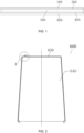
- the membrane body comprises a first PET layer 100, a first electric conduction layer 200, a liquid crystal layer 300, a second electric conduction layer 400, and a second PET layer 500, which are included sequentially from top to bottom.
- the first electrode is provided on the second electric conduction layer 400; and the second electrode is provided on the first electric conduction layer 200.
- the PDLC membrane can be manufactured by the aforementioned method for manufacturing a PDLC membrane electrode, wherein the technical advantages and effects achieved by the PDLC membrane also include the technical advantages and effects achieved by the method for manufacturing a PDLC membrane electrode, which will not be repeated again here.
- the present invention provides a method for manufacturing a PDLC membrane electrode, which can reduce participation by human, improve production efficiency, and produce a PDLC membrane with improved electrode performance.
- the electrode can be made according to any patterns.
Landscapes
- Physics & Mathematics (AREA)
- Nonlinear Science (AREA)
- Chemical & Material Sciences (AREA)
- Optics & Photonics (AREA)
- Crystallography & Structural Chemistry (AREA)
- General Physics & Mathematics (AREA)
- Mathematical Physics (AREA)
- Engineering & Computer Science (AREA)
- Dispersion Chemistry (AREA)
- Chemical Kinetics & Catalysis (AREA)
- General Chemical & Material Sciences (AREA)
- Oil, Petroleum & Natural Gas (AREA)
- Plasma & Fusion (AREA)
- Mechanical Engineering (AREA)
- Manufacturing & Machinery (AREA)
- Liquid Crystal (AREA)
- Devices For Indicating Variable Information By Combining Individual Elements (AREA)
- Laminated Bodies (AREA)
Description
- This invention claims the priority of a Chinese patent application filed with the
Chinese Patent Office on December 14, 2020, with the application number 2020114707719 - The present invention relates to the technical field of electrode processing, and in particular, to a method for manufacturing a PDLC membrane electrode, a negative pressure platform and a PDLC membrane.
- Polymer Dispersed Liquid Crystal (referred to as PDLC) is a new type of optoelectronic film material, that is, liquid crystal is dispersed in a polymer, and the formed liquid crystal droplets, under certain conditions, are uniformly dispersed in a continuous polymer matrix through polymerization reaction. Due to the optical anisotropy and dielectric anisotropy of liquid crystal molecules, PDLC becomes a composite material with electro-optical response characteristics.
- Generally, the production of a PDLC membrane electrode is one of the core processes, and its main function is to connect and energize the conductive films on both sides of the PDLC membrane, so as to deflect the liquid crystal. Herein, the quality of electrode production directly lead to whether the membrane can be driven normally, whether it is fully driven, and whether there is breakdown or short circuit near the electrode.
- At present, the electrode production process of PDLC membranes on the market comprises: manually cutting into sheets, dividing PDLC membrane electrodes, and erasing PDLC adhesive layer with alcohol, etc., which are basically manual operations. For example, one sheet with a size of 5000mm×1500mm×500mm requires the workload of one worker working for five hours, resulting in low work efficiency and low precision; alternatively, it is processed by semiautomatic equipment and then spliced manually, leading to the relatively low yield of the electrode production and the relatively low efficiency.
-
WO2020071110A1 provides a method of manufacturing a dimming element which is capable of forming an extraction electrode part without damaging a transparent electrode layer or causing problems in the work environment. This method of manufacturing a dimming element includes: removing, from a predetermined portion of a dimming film that has a first substrate with a transparent electrode layer and a second substrate with a transparent electrode layer, which are arranged so that the transparent electrode layers face one another, and a liquid crystal dimming layer that is sandwiched between the substrates with the transparent electrode layers, one of the substrates with the transparent electrode layers; using an organic solvent to cause the liquid crystal dimming layer that remains in the predetermined portion after the one of the substrates with the transparent electrode layers is removed to swell; attaching an adhesive tape to a surface of the swollen liquid crystal dimming layer; and peeling the adhesive tape together with the swollen liquid crystal dimming layer away from the dimming film. -
WO2020054445A1 provides a method for obtaining a dimming element that has a lead-out electrode without breaking a transparent electrode layer that is the transparent electrode layer used as a lead-out electrode. This method for manufacturing a dimming element that has a lead-out electrode comprises: a step of obtaining a dimming film (100) that includes a first transparent electrode layer-attached base material (10) and a second transparent electrode layer-attached base material (20) which are arranged so that the transparent electrode layers face each other and a liquid crystal dimming layer (30) interposed between the transparent electrode layer-attached base materials, the dimming film further including an extended section that extends in a direction perpendicular to the thickness direction; a step of peeling one transparent electrode layer-attached base material (20) from the dimming film (100) by inserting a peeling means (200) between the transparent electrode layer-attached base materials at the extended section; and a step of bending the peeled portion of the one transparent electrode layer-attached base material (20) outward and breaking the peeled portion. The breakage diameter of the one transparent electrode layer-attached base material (20) is 0.1 - 5 mm. -
JP4655406B2 -
KR102176615B1 - The present invention provides a method for manufacturing a PDLC membrane electrode, in which the contents of the method is the same as the pending claims.
- In order to more clearly describe the technical solutions in the embodiments of the present invention, the drawings that need to be used in the description of the embodiments will be briefly introduced as follows. It should be understood that the drawings in the following description are some embodiments of the present invention. For those ordinarily skilled in the art, without inventive effort, other related drawings can also be obtained based on these drawings.
-
FIG. 1 is a schematic sectional view of a PDLC membrane provided by an embodiment of the invention; -
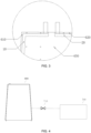
FIG. 2 is a schematic top view of a negative pressure platform provided by an embodiment of the invention; -
FIG. 3 is a partial enlarged schematic diagram of A part shown inFIG. 2 ; and -
FIG. 4 is a schematic view showing the negative pressure platform provided by an embodiment of the invention and the vacuum device in the fluid communication. -
- 10-front side half-cut area; 20-back side half-cut area;
- 100-first PET layer (first base membrane); 200-first electric conduction layer;
- 300-liquid crystal layer; 400-second electric conduction layer; 500-second PET layer (second base membrane);
- 600-negative pressure platform; 610-first transparent area; 620-second transparent area; 630-transparent area; 640-main body area; 650-vent hole;
- 700-vacuum device; and 710-valve.
- In order to make the objectives, technical solutions and advantages of the present invention clearer, the technical solutions in the embodiments of the present invention will be described clearly and completely with reference to the drawings. Obviously, the described embodiments are part of the embodiments of the present invention, not all of them. The components of the embodiments of the present invention described and illustrated in the drawings herein may be generally arranged and designed in a variety of different configurations.
- Therefore, the following detailed description of the embodiments of the present invention, provided in the drawings, is not intended to limit the scope of the claimed present invention, but merely represents selected embodiments of the present invention. Based on the embodiments in the present invention, all other embodiments obtained by those ordinarily skilled in the art without creative work shall fall within the protection scope of the present invention.
- It should be noted that similar reference numbers and letters indicate similar items in the following drawings. Therefore, once a certain item is defined in one drawing, it does not need to be further defined and explained in the subsequent drawings.
- In the description of the present invention, it should be noted that the orientation or positional relationship indicated by the terms such as "center", "upper", "lower", "left", "right", "vertical", "horizontal", "inner", "outer", "front side", "back side", is based on the orientation or positional relationship shown in the drawings, or the orientation or positional relationship when the product of the invention is usually placed in use, and it is only for the convenience of describing the present invention and simplifying the description, rather than indicating or implying that the indicated device or element must be of the specific orientation, or be configured and operated in the specific orientation, and therefore cannot be understood as a limitation to the present invention. In addition, the terms "first", "second", "third", etc. are only used for describing the distinguishing, and cannot be understood as indicating or implying the importance of the relativity.
- In addition, terms, such as "horizontal" and "vertical", do not mean that the component is required to be absolutely horizontal or overhanging, but may be slightly inclined. For example, "horizontal" only means that its direction is more horizontal than "vertical", which does not mean that the structure must be completely horizontal, but can be slightly inclined.
- In the description of the present invention, it should also be noted that, unless otherwise clearly stipulated and defined, the terms such as "provide", "mount", "link", "connect", should be understood in a broad sense, and for example, they may be fixedly connected and can also be detachably connected or integrally connected; or they can be mechanically connected or electrically connected; or they can be directly connected or indirectly connected through an intermediate medium, and the two components can be the internally communicated. For those ordinarily skilled in the art, the specific meanings of the above-mentioned terms in the present invention can be understood in specific situations.
- The term "negative pressure platform" as used herein has the meaning commonly understood by those skilled in the art. "Negative pressure" refers to any suitable negative pressure that allows the PDLC membrane to be processed to be adsorbed onto the platform so that it remains flat and does not warp. The size and shape of the negative pressure platform can be set according to the PDLC membrane to be processed and the desired product. The negative pressure platform can be of various possible shapes.
- The negative pressure platform in the present invention comprises a transparent area. The term "transparent area" as used herein refers to an area made of transparent material. The transparent material can allow laser light to transmit therethrough, thereby minimizing the absorption and reflection for laser light. In the present invention, the main body area of the negative pressure platform is usually a metal material area, taking into account the characteristics of low wear and long service life of the metal material, but any other suitable material may also be used, and for example, it is a transparent material as well.
- The negative pressure platform in the present invention comprises a negative pressure bonding area.
- The term "liquid crystal activation area" as used herein refers to the area of the PDLC membrane where the liquid crystal layer needs to be activated. The transparent area of the negative pressure platform is adapted to the "liquid crystal activation area".
- The term "other area" as used herein refers to the area of the PDLC membrane other than the "liquid crystal activation area". The "other area" is adapted to the main body area of the negative pressure platform (for example, the metal material area). The "other area" may also be referred to as "non-liquid crystal activation area".
- The term "half-cut area" as used herein refers to an area on the negative pressure platform, used to guide where to cut and tear off the PDLC membrane. The half-cut area on the negative pressure platform may be located more inwardly than the transparent area, or may coincide with the inner-side boundary of the transparent area. The sizes and shapes of the half-cut area and the transparent area on the negative pressure platform can all be changed in any appropriate way, as needed.
- Hereinafter, some embodiments of the present invention will be described in detail with reference to the drawings. In the case of no conflict, the following embodiments and features in the embodiments can be combined with each other.
- This embodiment provides a method for manufacturing a PDLC membrane electrode. Referring to
FIGS. 1 to 3 , the method for manufacturing a PDLC membrane electrode comprises the following steps: - placing the PDLC membrane on the
negative pressure platform 600 with the side to be processed facing upwards, and making the liquid crystal activation area of the side to be processed of the PDLC membrane coincide with thetransparent area 630 of thenegative pressure platform 600, and the other areas coincide with the metal material area of thenegative pressure platform 600; - activating the liquid crystal layer of the PDLC membrane (the liquid crystal activation area of the side to be processed); and
- cutting and tearing off, according to the half-cut area, the PET layer and the electric conduction layer located on the
liquid crystal layer 300, and sweeping off the activatedliquid crystal layer 300 to expose the electric conduction layer located under theliquid crystal layer 300 to form a corresponding electrode. In this embodiment, the method for manufacturing a PDLC membrane electrode may include a front side processing step and a back side processing step. - Specifically, referring to
FIGS. 2 and3 , the PDLC membrane is placed on thenegative pressure platform 600 with the front side facing upwards, and the front side liquid crystal activation area of the PDLC membrane coincides with the firsttransparent area 610 of thenegative pressure platform 600, and the other areas coincides with the metal material area of thenegative pressure platform 600. Theliquid crystal layer 300 of the PDLC membrane (the front side liquid crystal activation area) is activated. According to the front side half-cutarea 10, thefirst PET layer 100 and the firstelectric conduction layer 200 located on theliquid crystal layer 300 are cut and torn off. The activatedliquid crystal layer 300 is swept off to expose the secondelectric conduction layer 400 to form a first electrode. - The PDLC membrane is placed on the
negative pressure platform 600 with the back side facing upwards, and the back side liquid crystal activation area of the PDLC membrane is made to coincide with the secondtransparent area 620 of thenegative pressure platform 600, and other areas coincide with the metal material area of thenegative pressure platform 600. Theliquid crystal layer 300 of the PDLC membrane (the back side liquid crystal activation area) is activated. According to the back side half-cutarea 20, thesecond PET layer 500 and the secondelectric conduction layer 400 located on theliquid crystal layer 300 are cut and torn off. The activatedliquid crystal layer 300 is swept off to expose the firstelectric conduction layer 200 to form a second electrode. Optionally, in the activation step, an infrared laser is used for activation. - In some embodiments, when an infrared laser is used for activation, the infrared laser can use the following parameters, wherein
- the wavelength range is 955~1068nm;
- the frequency range is 20~80khz;
- the energy range is 1~5J/sec;
- the filling density range is 0.002~0.05mm;
- the processing speed range is 500~8000mm/sec;
- the processing thickness range is 0.05-0.3 mm;
- the processing width range is 1-20 mm; and
- the processing time range is 2hr.
- In some embodiments, when cutting according to the half-cut area, a carbon dioxide laser is used for cutting.
- In some embodiments, when a carbon dioxide laser is used for cutting, the carbon dioxide laser can use the following parameters, wherein
- the wavelength is 9.3~10.6µm;
- the power is 60~120W;
- the frequency range is 30~100khz; and
- the cutting speed range is 80~200mm/sec. Optionally, the PET layer and the electric conduction layer located on the liquid crystal layer are manually or mechanically torn off according to the half-cut area.
- It should be noted that
FIGS. 2 and3 only exemplarily show the negative pressure platform in the case of activating the side part of the PDLC membrane, where the first transparent area and the second transparent area can be arranged in different ways, such as having different sizes and shapes. In other words, the front and back sides of the PDLC membrane can be processed in different sizes and shapes, and the processing parameters can also be set differently. In the present invention, the terms "front side" and "back side" are only used to distinguish two opposite surfaces of the PDLC membrane, and do not indicate a specific order, structure or the like. - It should also be noted that, in the front side processing step, the activated
liquid crystal layer 300 has basically separated from the firstelectric conduction layer 200 and the secondelectric conduction layer 400. After thefirst PET layer 100 and the firstelectric conduction layer 200 are torn off, a part of theliquid crystal layer 300 can be taken away, and a part of theliquid crystal layer 300 remains in the secondelectric conduction layer 400. It is possible to use a brush, dust-free cloth or technical foam, etc., to sweep off the remaining part ofliquid crystal layer 300, exposing the secondelectric conduction layer 400, to form the first electrode. Similarly, the same operation can be used for the back side processing steps, which will not be repeated here. However, if the liquid crystal is not activated, the manual wiping, using e.g. alcohol, is required to wipe off theliquid crystal layer 300, which is not only inefficient, but also possible of having the problems, such as incomplete wiping or excessive wiping, which affects the performance of the electrode. - In the method for manufacturing the PDLC membrane electrode provided by this embodiment, the liquid crystal activation area of the side to be processed of the PDLC membrane coincides with the
transparent area 630 of thenegative pressure platform 600, and other areas coincide with the metal material area of thenegative pressure platform 600. With this arrangement, during performing the activation, the laser light can be made to only penetrate to the transparent area of the negative pressure platform, and not touch the main body area of the negative pressure platform (for example, the metal material area). Since laser light absorbed and reflected by the transparent area is relatively small, a better liquid crystal activation effect is achieved, which is beneficial to the removal of the liquid crystal layer. In addition, it is possible to prevent the laser from passing through the transparent area and acting on, for example, the metal material area to generate heat, causing the PDLC membrane to be burned out, thereby improving the pass rate of the PDLC membrane. In addition, the method for manufacturing a PDLC membrane electrode can reduce the participation by human, increasing the production output, and improving the production efficiency. In addition, according to the different cutting areas, the electrode can be made according to any pattern. - This embodiment also provides a method for manufacturing a PDLC membrane electrode. Referring to
FIGS. 1 to 3 , the method for manufacturing a PDLC membrane electrode comprises the following steps: - placing the PDLC membrane on the
negative pressure platform 600 with the side to be processed facing upwards, wherein thenegative pressure platform 600 comprises atransparent area 630 and amain body area 640, and the liquid crystal activation area of the side to be processed of the PDLC membrane and thetransparent area 630 of thenegative pressure platform 600 are made to coincide with each other, and other areas coincide with themain body area 640 of thenegative pressure platform 600; - activating the liquid crystal layer of the liquid crystal activation area on the side to be processed of the PDLC membrane; and
- cutting, according to the half-cut area, the PET layer and the electric conduction layer located on the
liquid crystal layer 300, and tearing off the PET layer, the electric conduction layer and the activatedliquid crystal layer 300 together to expose the electric conduction layer below theliquid crystal layer 300 to form the corresponding electrode. - According to the claimed invention, the method for manufacturing a PDLC membrane electrode includes a front side processing step and a back side processing step.
- Specifically, referring to
FIGS. 2 and3 , the PDLC membrane is placed on thenegative pressure platform 600 with the front side facing upwards, and the front side liquid crystal activation area of the PDLC membrane is made to coincide with the firsttransparent area 610 of thenegative pressure platform 600, and the other areas coincide with themain body area 640 of thenegative pressure platform 600; theliquid crystal layer 300 of the front side liquid crystal activation area of the PDLC membrane is activated; thefirst PET layer 100 and the firstelectric conduction layer 200 located on theliquid crystal layer 300 are cut according to the front side half-cutarea 10, and thefirst PET layer 100, the firstelectric conduction layer 200, and the activatedliquid crystal layer 300 are together torn off to expose the secondelectric conduction layer 400 to form a first electrode. - The PDLC membrane is placed on the
negative pressure platform 600 with the back side facing upwards, and the back side liquid crystal activation area of the PDLC membrane is made to coincide with the secondtransparent area 620 of thenegative pressure platform 600, and other areas coincide with themain body area 640 of thenegative pressure platform 600; theliquid crystal layer 300 in the back side liquid crystal activation area of the PDLC membrane is activated; according to the back side half-cutarea 20, thesecond PET layer 500 and the secondelectric conduction layer 400 located on theliquid crystal layer 300 are cut, and thesecond PET layer 500, the secondelectric conduction layer 400 and the activatedliquid crystal layer 300 are torn off together to expose the firstelectric conduction layer 200 to form a second electrode. - In some embodiments, the
main body area 640 of thenegative pressure platform 600 is a metal material area. - Referring to
FIGS. 3 and 4 , thenegative pressure platform 600 may include a plurality of vent holes 650. In some embodiments, themain body area 640 of the negative pressure platform comprises a plurality of vent holes 650. In some embodiments, thetransparent area 630 of the negative pressure platform comprises a plurality of vent holes 650. In some embodiments, both themain body area 640 and thetransparent area 630 of the negative pressure platform include a plurality of vent holes 650. Eachvent hole 650 is in fluid communication with a vacuum device (for example, a vacuum pump) 700. In some embodiments, thevent hole 650 has a diameter of 0.5 to 3.0 mm, 0.8 to 2.5 mm, or 1 to 2 mm. In some embodiments, the hole spacing between adjacent vent holes 650 is 10-50 mm, 15-40 mm, or 20-30 mm. In some embodiments, a valve 710 (such as a solenoid valve) is provided between thevent hole 650 and the vacuum device (such as a vacuum pump) 700. Thevalve 710 can control the fluid communication between thevent hole 650 and thevacuum device 700, for example, opening or cut off the fluid communication between the two. Thevacuum device 700 provides negative pressure, so that the PDLC membrane to be processed can be smoothly adsorbed on thenegative pressure platform 600 without warping, and the start and stop of the vacuum adsorption can be controlled through the PLC control terminal. - In some embodiments, in the activation step, an infrared laser is used for activation.
- In some embodiments, when an infrared laser is used for activation, the infrared laser uses the following parameters, wherein
- the wavelength range is 955~1068nm;
- the frequency range is 20~80khz;
- the energy range is 1~5J/sec;
- the filling density range is 0.002~0.05mm;
- the processing speed range is 500~8000mm/sec;
- the processing thickness range is 0.05-0.3 mm;
- the processing width range is 1-20 mm; and
- the processing time range is 2hr.
- In some embodiments, when cutting according to the half-cut area, a carbon dioxide laser is used for cutting.
- In some embodiments, when a carbon dioxide laser is used for cutting, the carbon dioxide laser can use the following parameters, wherein
- the wavelength is 9.3∼10.6µm;
- the power is 60~120W;
- the frequency range is 30~100khz; and
- the cutting speed range is 80∼200mm/sec.
- In some embodiments, the PET layer and the electric conduction layer located on the liquid crystal layer are torn off manually or mechanically according to the half-cut area.
- It should be noted that, as shown in
FIG. 2 andFIG. 3 , the aforementioned "main body area" is the part of thenegative pressure platform 600, which remains after removing the firsttransparent area 610 and the secondtransparent area 620. - It should also be noted that in the above-mentioned front side processing step, the activated
liquid crystal layer 300 has been separated from the secondelectric conduction layer 400. After thefirst PET layer 100 and the firstelectric conduction layer 200 are torn off, all of theliquid crystal layer 300 can be taken away, with noliquid crystal layer 300 leaving on the secondelectric conduction layer 400, therefore there is no need for a sweeping step; and similarly, the same operation can be used for the back side processing step, which will not be repeated here. However, if the liquid crystal is not activated or the activation effect is not enough to take away all of theliquid crystal layer 300, it is necessary to manually wipe, with e.g. alcohol, to wipe off theliquid crystal layer 300, or use other methods to clean the remainingliquid crystal layer 300, which is not only inefficient, but also possible of having the problem of incomplete wiping or excessive wiping, which affects the performance of the electrode. - In addition, due to the reasons, such as, the liquid crystal activation effect is better in the method of this embodiment and better liquid crystal layer removal is achieved, the PDLC membrane, which is obtained by the above processing method, will obtain a resistance value in a stable range when measured by resistance gauge. Especially, when there is no need to sweep the liquid crystal layer, it is possible to eliminate the shortcomings caused by manual wiping of the liquid crystal layer so that the obtained PDLC membrane has a resistance value in a stable range. For example, as for a PDLC membrane with an electric conduction layer being of 160 ohm before processing, the measured resistance value is 250 ± 50 ohm after the electrode is fabricated by the above method, and the customer standard is usually below 300 ohm. However, if the liquid crystal layer is not activated or the activation effect is not good, manual wiping is required. Because manual wiping has differences caused by human and the uncertainty of the wiping effect, it is usually time-consuming and difficult to obtain a resistance value in a stable range. The resistance value of the electrode obtained by wiping the liquid crystal layer may be as high as 500 ohm.
- In summary, the method for manufacturing a PDLC membrane electrode can have the following advantages.
- (1) The activation of the liquid crystal layer is performed in combination with the transparent area of the negative pressure platform, to achieve a better liquid crystal activation effect, which can make part or all of the liquid crystal layer and the electric conduction layer torn off together, simplifying or avoiding the steps of sweeping the liquid crystal layer.
- (2) The resistance value after the production is in a stable range.
- (3) The laser cutting is adopted with the laser being used for the non-contact cutting, which will not cause the double-layer membrane to be separated due to an external force.
- (4) It can be cut according to any patterns without masking.
- (5) The participation by human is reduced and the production efficiency is improved.
- The disclosure provides a
negative pressure platform 600 that implements the aforementioned method for manufacturing a PDLC membrane electrode. Thenegative pressure platform 600 comprises atransparent area 630 that matches the liquid crystal activation area of the PDLC membrane. Themain body area 640 of thenegative pressure platform 600 may be a metal material area or area made of any other suitable material. - In some examples, the
negative pressure platform 600 comprises a first transparent area 610 (coinciding with the front side liquid crystal activation area), a second transparent area 620 (coinciding with the back side liquid crystal activation area), and a main body area 640 (for example, a metal material area). - In some examples, , the material of the metal material region is steel or aluminum.
- In some examples, the material of the
transparent region 630 is transparent organic glass or inorganic glass. In some embodiments, the material of thetransparent region 630 is a transparent polyacrylic resin, such as polymethyl methacrylate (acrylic). In some embodiments, the material of thetransparent region 630 is transparent polymethyl methacrylate (acrylic) or crystal glass. - In this example, the
negative pressure platform 600 may be of a plate-shaped structure. - In some examples, the thickness of the
negative pressure platform 600 is greater than 15 mm. Exemplarily, the thickness of thenegative pressure platform 600 may be 15 mm, 16 mm, 17 mm, or the like. In addition, the thickness of thenegative pressure platform 600 is generally less than 20 mm. - The negative pressure platform provided in this example can be applied to the aforementioned method for manufacturing a PDLC membrane electrode. Here, the technical advantages and effects achieved by the method for manufacturing a PDLC membrane electrode also include the technical advantages and effects achieved by the negative pressure platform, which is not repeated again here.
- As shown in
FIG. 1 , this disclosure also provides a PDLC membrane produced by the aforementioned method for manufacturing a PDLC membrane electrode. The PDLC membrane comprises a membrane body, a first electrode (not shown in the drawings), and a second electrode (not shown in the drawings). The membrane body comprises afirst PET layer 100, a firstelectric conduction layer 200, aliquid crystal layer 300, a secondelectric conduction layer 400, and asecond PET layer 500, which are included sequentially from top to bottom. The first electrode is provided on the secondelectric conduction layer 400; and the second electrode is provided on the firstelectric conduction layer 200. - The PDLC membrane can be manufactured by the aforementioned method for manufacturing a PDLC membrane electrode, wherein the technical advantages and effects achieved by the PDLC membrane also include the technical advantages and effects achieved by the method for manufacturing a PDLC membrane electrode, which will not be repeated again here.
- Finally, it should be noted that the above individual embodiments are only used to illustrate the technical solutions of the present invention, not to limit it. Although the present invention has been described in detail with reference to the foregoing individual embodiments, those ordinarily skilled in the art should understand that the technical solutions recorded in the foregoing individual embodiments can still be modified, or some or all of the technical features thereof can be equivalently replaced and these modifications or replacements do not make the essence of the corresponding technical solutions deviate from the scope of the technical solutions of the embodiments of the present invention.
- In summary, the present invention provides a method for manufacturing a PDLC membrane electrode, which can reduce participation by human, improve production efficiency, and produce a PDLC membrane with improved electrode performance. In addition, depending on different cutting areas, the electrode can be made according to any patterns.
Claims (8)
- A method for manufacturing a PDLC membrane electrode,wherein the polymer dispersed liquid crystal, PDLC, membrane comprises: a liquid crystal layer (300); electric conduction layers (200, 400), respectively arranged on both sides of the liquid crystal layer (300); and base membranes (100, 500), respectively arranged on outer sides of the electric conduction layers (200, 400); andthe method comprises following steps:placing the PDLC membrane on a negative pressure platform (600) with a side to be processed facing upwards, wherein the negative pressure platform (600) comprises a transparent area (630) and a main body area (640), and making a liquid crystal activation area of the PDLC membrane coincide with the transparent area (630) of the negative pressure platform (600), and area other than the liquid crystal activation area of the PDLC membrane fit to the main body area (640) of the negative pressure platform (600);activating the liquid crystal layer (300) of the liquid crystal activation area of the side to be processed of the PDLC membrane; andcutting, according to a half-cut area, a base membrane and an electric conduction layer located on the liquid crystal layer (300), and tearing off the base membrane, the electric conduction layer and an activated liquid crystal layer (300) together to expose an electric conduction layer located under the liquid crystal layer (300) to form a corresponding electrode; wherein a half-cut area is an area on the negative pressure platform, used to guide where to cut and tear off the PDLC membrane;the method comprising a front side processing step and a back side processing step, wherein , during the front side processing step, the PDLC membrane is placed on the negative pressure platform (600) with a front side facing upwards, and a front side liquid crystal activation area of the PDLC membrane is made to coincide with a first transparent area (610) of the negative pressure platform (600) and area other than the liquid crystal activation area of the PDLC membrane is attached to the main body area (640) of the negative pressure platform (600); the liquid crystal layer (300) of the front side liquid crystal activation area of the PDLC membrane is activated such that the activated liquid crystal layer (300) is separated from the second electric conduction layer (400); according to a front side half-cut area (10), a first base membrane (100) and a first electric conduction layer (200) located on the liquid crystal layer (300) are cut, and the first base membrane (100), the first electric conduction layer (200) and the activated liquid crystal layer (300) are together torn off to expose a second electric conduction layer (400) to form a first electrode; andwherein, during the back side processing step, the PDLC membrane is placed on the negative pressure platform (600) with a back side facing upwards, and a back side liquid crystal activation area of the PDLC membrane is made to coincide with a second transparent area (620) of the negative pressure platform (600) and area other than the liquid crystal activation area of the PDLC membrane is attached to the main body area (640) of the negative pressure platform (600); the liquid crystal layer (300) of the back side liquid crystal activation area of the PDLC membrane is activated such that the activated liquid crystal layer (300) is separated from the first electric conduction layer (200); according to a back side half-cut area (20), a second base membrane (500) and the second electric conduction layer (400) located on the liquid crystal layer (300) are cut, and the second base membrane (500), the second electric conduction layer (400) and the activated liquid crystal layer (300) are together torn off to expose the first electric conduction layer (200) to form a second electrode;wherein in an activation step, an infrared laser is used for activation.
- The method for manufacturing a PDLC membrane electrode according to claim 1, wherein the base membrane is a PET layer.
- The method for manufacturing a PDLC membrane electrode according to claim 1, wherein the infrared laser uses following parameters, whereina wavelength range is 955~1068nm;a frequency range is 20~80khz;an energy range is 1~5J/sec;a filling density range is 0.002~0.05mm;a processing speed range is 500~8000mm/sec;a processing thickness range is 0.05-0.3 mm;a processing width range is 1-20 mm; anda processing time range is 2hr.
- The method for manufacturing a PDLC membrane electrode according to any one of claims 1-3, wherein material of the transparent region (630) is selected from transparent organic glass or inorganic glass.
- The method for manufacturing a PDLC membrane electrode according to claim 4, wherein the material of the transparent region (630) is selected from transparent polymethyl methacrylate or crystal glass.
- The method for manufacturing a PDLC membrane electrode according to any one of claims 1-5, wherein the main body area (640) of the negative pressure platform (600) is a metal material area.
- The method for manufacturing a PDLC membrane electrode according to any one of claims 1-6, wherein the negative pressure platform (600) comprises a plurality of vent holes (650) in fluid communication with a vacuum device (700), so that a PDLC membrane to be processed is adsorbed on the platform.
- The method for manufacturing a PDLC membrane electrode according to any one of claims 1-6, wherein when cutting according to the half-cut area, a carbon dioxide laser is used for cutting.
Applications Claiming Priority (2)
| Application Number | Priority Date | Filing Date | Title |
|---|---|---|---|
| CN202011470771.9A CN112596291B (en) | 2020-12-14 | 2020-12-14 | PDLC membrane electrode manufacturing method, negative pressure platform and PDLC membrane |
| PCT/CN2021/075325 WO2022126847A1 (en) | 2020-12-14 | 2021-02-04 | Pdlc film electrode manufacturing method, negative pressure platform, and pdlc film |
Publications (4)
| Publication Number | Publication Date |
|---|---|
| EP4036640A1 EP4036640A1 (en) | 2022-08-03 |
| EP4036640A4 EP4036640A4 (en) | 2022-12-07 |
| EP4036640C0 EP4036640C0 (en) | 2025-05-14 |
| EP4036640B1 true EP4036640B1 (en) | 2025-05-14 |
Family
ID=75196486
Family Applications (1)
| Application Number | Title | Priority Date | Filing Date |
|---|---|---|---|
| EP21865359.0A Active EP4036640B1 (en) | 2020-12-14 | 2021-02-04 | Pdlc film electrode manufacturing method |
Country Status (6)
| Country | Link |
|---|---|
| US (1) | US12253767B2 (en) |
| EP (1) | EP4036640B1 (en) |
| JP (1) | JP7301174B2 (en) |
| KR (1) | KR102769768B1 (en) |
| CN (1) | CN112596291B (en) |
| WO (1) | WO2022126847A1 (en) |
Families Citing this family (2)
| Publication number | Priority date | Publication date | Assignee | Title |
|---|---|---|---|---|
| CN115291444B (en) * | 2022-09-02 | 2024-03-15 | 上海隆昇光电新材料有限公司 | Partition dimming film, electrode manufacturing method and laser cutting device |
| CN118417270A (en) * | 2023-07-31 | 2024-08-02 | 昆山阿利曼自动化激光设备有限公司 | A cleaning device and method for liquid crystal on the electrode side of a dimming film |
Citations (2)
| Publication number | Priority date | Publication date | Assignee | Title |
|---|---|---|---|---|
| JP4655406B2 (en) * | 2001-05-11 | 2011-03-23 | 株式会社東京精密 | Surface emitting suction table |
| KR102176615B1 (en) * | 2020-07-03 | 2020-11-09 | (주)디바이스이엔지 | Apparatus and Method for Transferring Disply Element |
Family Cites Families (16)
| Publication number | Priority date | Publication date | Assignee | Title |
|---|---|---|---|---|
| JP2001059954A (en) * | 1999-08-23 | 2001-03-06 | Minolta Co Ltd | Method for recording picture on thermally reversible recording medium |
| JP2003294950A (en) * | 2002-02-01 | 2003-10-15 | Dainippon Printing Co Ltd | Liquid crystal film patterning method |
| JP2004050797A (en) * | 2002-07-24 | 2004-02-19 | Dainippon Printing Co Ltd | Method for producing master for optical element and master for optical element |
| KR100856151B1 (en) * | 2006-11-06 | 2008-09-03 | 아이디 리써치 피티와이 리미티드 | Manufacturing method of electrode terminal part of polymer dispersed liquid crystal display |
| ES2748829T3 (en) * | 2010-03-29 | 2020-03-18 | Ravenbrick Llc | Polymer stabilized thermotropic liquid crystal device |
| US20190255812A1 (en) * | 2016-02-01 | 2019-08-22 | Central Glass Company, Limited | Polymer dispersed liquid crystal glass construction |
| JP2019184909A (en) * | 2018-04-13 | 2019-10-24 | 凸版印刷株式会社 | Connecting equipment |
| CN108445667A (en) * | 2018-05-15 | 2018-08-24 | 高志超 | A kind of electronics blinds film, glass and control system based on PDLC liquid crystal light modulation films |
| CN108957801A (en) * | 2018-07-19 | 2018-12-07 | 张家港康得新光电材料有限公司 | A kind of online production method of the electrode of pdlc film and equipment |
| KR102721282B1 (en) | 2018-09-10 | 2024-10-23 | 닛토덴코 가부시키가이샤 | Method for manufacturing a light emitting element |
| JP7332616B2 (en) | 2018-10-04 | 2023-08-23 | 日東電工株式会社 | Method for manufacturing light modulating element |
| JP7310247B2 (en) * | 2019-04-12 | 2023-07-19 | 凸版印刷株式会社 | Light control sheet and method for manufacturing light control sheet |
| CN109976062B (en) * | 2019-04-12 | 2025-01-17 | 深圳市宝立创科技有限公司 | Liquid crystal film cutting method and cholesteric liquid crystal film |
| CN110471206A (en) * | 2019-07-23 | 2019-11-19 | 珠海兴业新材料科技有限公司 | A kind of method that laser direct etching is prepared with the PDLC liquid crystal light modulation film of pattern and/or text |
| CN111308756B (en) * | 2019-12-20 | 2024-03-22 | 章思 | Half-cut liquid crystal film and processing method |
| CN111381395B (en) * | 2020-01-21 | 2023-11-28 | 奥提赞光晶(山东)显示科技有限公司 | Electric control continuous zoom lens, preparation method and exposure system |
-
2020
- 2020-12-14 CN CN202011470771.9A patent/CN112596291B/en active Active
-
2021
- 2021-02-04 WO PCT/CN2021/075325 patent/WO2022126847A1/en not_active Ceased
- 2021-02-04 EP EP21865359.0A patent/EP4036640B1/en active Active
- 2021-02-04 KR KR1020227006720A patent/KR102769768B1/en active Active
- 2021-02-04 US US17/766,700 patent/US12253767B2/en active Active
- 2021-02-04 JP JP2021572841A patent/JP7301174B2/en active Active
Patent Citations (2)
| Publication number | Priority date | Publication date | Assignee | Title |
|---|---|---|---|---|
| JP4655406B2 (en) * | 2001-05-11 | 2011-03-23 | 株式会社東京精密 | Surface emitting suction table |
| KR102176615B1 (en) * | 2020-07-03 | 2020-11-09 | (주)디바이스이엔지 | Apparatus and Method for Transferring Disply Element |
Also Published As
| Publication number | Publication date |
|---|---|
| KR20220088676A (en) | 2022-06-28 |
| CN112596291B (en) | 2022-03-18 |
| JP7301174B2 (en) | 2023-06-30 |
| EP4036640C0 (en) | 2025-05-14 |
| EP4036640A1 (en) | 2022-08-03 |
| JP2023510064A (en) | 2023-03-13 |
| WO2022126847A1 (en) | 2022-06-23 |
| EP4036640A4 (en) | 2022-12-07 |
| KR102769768B1 (en) | 2025-02-17 |
| CN112596291A (en) | 2021-04-02 |
| US12253767B2 (en) | 2025-03-18 |
| US20230194936A1 (en) | 2023-06-22 |
Similar Documents
| Publication | Publication Date | Title |
|---|---|---|
| US7202923B2 (en) | Liquid crystal display with polarizer with inclined edge portion | |
| KR100563896B1 (en) | Liquid crystal panel, method and device for manufacturing liquid crystal panel, and polarizing plate stamping device | |
| US8419896B2 (en) | Semi-automated reworkability process for de-bonding a display | |
| KR102721282B1 (en) | Method for manufacturing a light emitting element | |
| JP2008201629A (en) | Manufacturing method of electrooptical device, separating method of substrate, and substrate separating device | |
| CN205793713U (en) | The attaching device of conducting resinl and rework system | |
| KR102059126B1 (en) | Backlight unit manufacturing method by using mini LED | |
| CN101505908A (en) | Laser separation of thin laminated glass substrates for flexible display applications | |
| CN111290174B (en) | Lamp panel, backlight module and display device | |
| US12253767B2 (en) | Method for manufacturing PDLC membrane electrode, negative pressure platform and PDLC membrane | |
| JP2010224422A (en) | Display device and manufacturing method thereof | |
| KR20100056037A (en) | Bonding system for liquid crystal display | |
| CN104166271A (en) | Optical film, manufacturing method thereof, backlight module and display device | |
| CN101344654B (en) | Conductive adhesive film cutting tool | |
| JPH11191341A (en) | High strength touch panel and manufacture thereof | |
| KR102829628B1 (en) | Manufacturing Method of Electrode Terminal Part of Polymer Dispersed Liquid Crystal Display | |
| KR102633196B1 (en) | Scribing apparatus and scribing method | |
| JP2009282107A (en) | Display panel and method for manufacturing the same | |
| CN221940594U (en) | Fixing device of mask plate and processing equipment of mask plate | |
| RU2358305C2 (en) | Device and method (versions) of changing size of electronic displays | |
| CN207521900U (en) | A kind of light guide plate side adhesive tape jig | |
| CN110884157A (en) | Method for cutting reflecting sheet of backlight module | |
| JP2018137403A (en) | Display device manufacturing method and light irradiation device | |
| JP2023076199A (en) | Semiconductor device manufacturing method | |
| JP2019039983A (en) | Intermediate for forming display device, display device, and method for manufacturing display device |
Legal Events
| Date | Code | Title | Description |
|---|---|---|---|
| STAA | Information on the status of an ep patent application or granted ep patent |
Free format text: STATUS: UNKNOWN |
|
| STAA | Information on the status of an ep patent application or granted ep patent |
Free format text: STATUS: THE INTERNATIONAL PUBLICATION HAS BEEN MADE |
|
| PUAI | Public reference made under article 153(3) epc to a published international application that has entered the european phase |
Free format text: ORIGINAL CODE: 0009012 |
|
| STAA | Information on the status of an ep patent application or granted ep patent |
Free format text: STATUS: REQUEST FOR EXAMINATION WAS MADE |
|
| 17P | Request for examination filed |
Effective date: 20220318 |
|
| AK | Designated contracting states |
Kind code of ref document: A1 Designated state(s): AL AT BE BG CH CY CZ DE DK EE ES FI FR GB GR HR HU IE IS IT LI LT LU LV MC MK MT NL NO PL PT RO RS SE SI SK SM TR |
|
| REG | Reference to a national code |
Free format text: PREVIOUS MAIN CLASS: G02F0001130000 Ipc: G02F0001133400 Ref country code: DE Ref legal event code: R079 Ref document number: 602021030919 Country of ref document: DE |
|
| STAA | Information on the status of an ep patent application or granted ep patent |
Free format text: STATUS: EXAMINATION IS IN PROGRESS |
|
| A4 | Supplementary search report drawn up and despatched |
Effective date: 20221108 |
|
| RIC1 | Information provided on ipc code assigned before grant |
Ipc: G02F 1/1345 20060101ALI20221102BHEP Ipc: G02F 1/1333 20060101ALI20221102BHEP Ipc: G02F 1/1334 20060101AFI20221102BHEP |
|
| 17Q | First examination report despatched |
Effective date: 20221122 |
|
| GRAP | Despatch of communication of intention to grant a patent |
Free format text: ORIGINAL CODE: EPIDOSNIGR1 |
|
| STAA | Information on the status of an ep patent application or granted ep patent |
Free format text: STATUS: GRANT OF PATENT IS INTENDED |
|
| INTG | Intention to grant announced |
Effective date: 20241205 |
|
| GRAS | Grant fee paid |
Free format text: ORIGINAL CODE: EPIDOSNIGR3 |
|
| GRAA | (expected) grant |
Free format text: ORIGINAL CODE: 0009210 |
|
| STAA | Information on the status of an ep patent application or granted ep patent |
Free format text: STATUS: THE PATENT HAS BEEN GRANTED |
|
| AK | Designated contracting states |
Kind code of ref document: B1 Designated state(s): AL AT BE BG CH CY CZ DE DK EE ES FI FR GB GR HR HU IE IS IT LI LT LU LV MC MK MT NL NO PL PT RO RS SE SI SK SM TR |
|
| REG | Reference to a national code |
Ref country code: GB Ref legal event code: FG4D |
|
| REG | Reference to a national code |
Ref country code: CH Ref legal event code: EP |
|
| REG | Reference to a national code |
Ref country code: IE Ref legal event code: FG4D |
|
| REG | Reference to a national code |
Ref country code: DE Ref legal event code: R096 Ref document number: 602021030919 Country of ref document: DE |
|
| U01 | Request for unitary effect filed |
Effective date: 20250606 |
|
| U07 | Unitary effect registered |
Designated state(s): AT BE BG DE DK EE FI FR IT LT LU LV MT NL PT RO SE SI Effective date: 20250616 |
|
| PG25 | Lapsed in a contracting state [announced via postgrant information from national office to epo] |
Ref country code: ES Free format text: LAPSE BECAUSE OF FAILURE TO SUBMIT A TRANSLATION OF THE DESCRIPTION OR TO PAY THE FEE WITHIN THE PRESCRIBED TIME-LIMIT Effective date: 20250514 |
|
| PG25 | Lapsed in a contracting state [announced via postgrant information from national office to epo] |
Ref country code: GR Free format text: LAPSE BECAUSE OF FAILURE TO SUBMIT A TRANSLATION OF THE DESCRIPTION OR TO PAY THE FEE WITHIN THE PRESCRIBED TIME-LIMIT Effective date: 20250815 Ref country code: NO Free format text: LAPSE BECAUSE OF FAILURE TO SUBMIT A TRANSLATION OF THE DESCRIPTION OR TO PAY THE FEE WITHIN THE PRESCRIBED TIME-LIMIT Effective date: 20250814 |
|
| PG25 | Lapsed in a contracting state [announced via postgrant information from national office to epo] |
Ref country code: PL Free format text: LAPSE BECAUSE OF FAILURE TO SUBMIT A TRANSLATION OF THE DESCRIPTION OR TO PAY THE FEE WITHIN THE PRESCRIBED TIME-LIMIT Effective date: 20250514 |
|
| PG25 | Lapsed in a contracting state [announced via postgrant information from national office to epo] |
Ref country code: HR Free format text: LAPSE BECAUSE OF FAILURE TO SUBMIT A TRANSLATION OF THE DESCRIPTION OR TO PAY THE FEE WITHIN THE PRESCRIBED TIME-LIMIT Effective date: 20250514 |
|
| PG25 | Lapsed in a contracting state [announced via postgrant information from national office to epo] |
Ref country code: RS Free format text: LAPSE BECAUSE OF FAILURE TO SUBMIT A TRANSLATION OF THE DESCRIPTION OR TO PAY THE FEE WITHIN THE PRESCRIBED TIME-LIMIT Effective date: 20250814 |
|
| PG25 | Lapsed in a contracting state [announced via postgrant information from national office to epo] |
Ref country code: IS Free format text: LAPSE BECAUSE OF FAILURE TO SUBMIT A TRANSLATION OF THE DESCRIPTION OR TO PAY THE FEE WITHIN THE PRESCRIBED TIME-LIMIT Effective date: 20250914 |
|
| PG25 | Lapsed in a contracting state [announced via postgrant information from national office to epo] |
Ref country code: SM Free format text: LAPSE BECAUSE OF FAILURE TO SUBMIT A TRANSLATION OF THE DESCRIPTION OR TO PAY THE FEE WITHIN THE PRESCRIBED TIME-LIMIT Effective date: 20250514 |
|
| PG25 | Lapsed in a contracting state [announced via postgrant information from national office to epo] |
Ref country code: CZ Free format text: LAPSE BECAUSE OF FAILURE TO SUBMIT A TRANSLATION OF THE DESCRIPTION OR TO PAY THE FEE WITHIN THE PRESCRIBED TIME-LIMIT Effective date: 20250514 |
|
| PG25 | Lapsed in a contracting state [announced via postgrant information from national office to epo] |
Ref country code: SK Free format text: LAPSE BECAUSE OF FAILURE TO SUBMIT A TRANSLATION OF THE DESCRIPTION OR TO PAY THE FEE WITHIN THE PRESCRIBED TIME-LIMIT Effective date: 20250514 |
|
| PLBE | No opposition filed within time limit |
Free format text: ORIGINAL CODE: 0009261 |
|
| STAA | Information on the status of an ep patent application or granted ep patent |
Free format text: STATUS: NO OPPOSITION FILED WITHIN TIME LIMIT |
|
| REG | Reference to a national code |
Ref country code: CH Ref legal event code: L10 Free format text: ST27 STATUS EVENT CODE: U-0-0-L10-L00 (AS PROVIDED BY THE NATIONAL OFFICE) Effective date: 20260325 |
|
| U20 | Renewal fee for the european patent with unitary effect paid |
Year of fee payment: 6 Effective date: 20260225 |
|
| 26N | No opposition filed |
Effective date: 20260217 |