EP4036595A1 - Objektdetektion mit mehreren bereichen und auflösungen - Google Patents
Objektdetektion mit mehreren bereichen und auflösungen Download PDFInfo
- Publication number
- EP4036595A1 EP4036595A1 EP22154478.6A EP22154478A EP4036595A1 EP 4036595 A1 EP4036595 A1 EP 4036595A1 EP 22154478 A EP22154478 A EP 22154478A EP 4036595 A1 EP4036595 A1 EP 4036595A1
- Authority
- EP
- European Patent Office
- Prior art keywords
- neural network
- deep neural
- output
- branch
- spatial
- Prior art date
- Legal status (The legal status is an assumption and is not a legal conclusion. Google has not performed a legal analysis and makes no representation as to the accuracy of the status listed.)
- Pending
Links
Images


Classifications
-
- G—PHYSICS
- G01—MEASURING; TESTING
- G01S—RADIO DIRECTION-FINDING; RADIO NAVIGATION; DETERMINING DISTANCE OR VELOCITY BY USE OF RADIO WAVES; LOCATING OR PRESENCE-DETECTING BY USE OF THE REFLECTION OR RERADIATION OF RADIO WAVES; ANALOGOUS ARRANGEMENTS USING OTHER WAVES
- G01S17/00—Systems using the reflection or reradiation of electromagnetic waves other than radio waves, e.g. lidar systems
- G01S17/02—Systems using the reflection of electromagnetic waves other than radio waves
- G01S17/06—Systems determining position data of a target
- G01S17/42—Simultaneous measurement of distance and other co-ordinates
-
- G—PHYSICS
- G01—MEASURING; TESTING
- G01S—RADIO DIRECTION-FINDING; RADIO NAVIGATION; DETERMINING DISTANCE OR VELOCITY BY USE OF RADIO WAVES; LOCATING OR PRESENCE-DETECTING BY USE OF THE REFLECTION OR RERADIATION OF RADIO WAVES; ANALOGOUS ARRANGEMENTS USING OTHER WAVES
- G01S13/00—Systems using the reflection or reradiation of radio waves, e.g. radar systems; Analogous systems using reflection or reradiation of waves whose nature or wavelength is irrelevant or unspecified
- G01S13/86—Combinations of radar systems with non-radar systems, e.g. sonar, direction finder
- G01S13/865—Combination of radar systems with lidar systems
-
- G—PHYSICS
- G01—MEASURING; TESTING
- G01S—RADIO DIRECTION-FINDING; RADIO NAVIGATION; DETERMINING DISTANCE OR VELOCITY BY USE OF RADIO WAVES; LOCATING OR PRESENCE-DETECTING BY USE OF THE REFLECTION OR RERADIATION OF RADIO WAVES; ANALOGOUS ARRANGEMENTS USING OTHER WAVES
- G01S7/00—Details of systems according to groups G01S13/00, G01S15/00, G01S17/00
- G01S7/48—Details of systems according to groups G01S13/00, G01S15/00, G01S17/00 of systems according to group G01S17/00
- G01S7/4802—Details of systems according to groups G01S13/00, G01S15/00, G01S17/00 of systems according to group G01S17/00 using analysis of echo signal for target characterisation; Target signature; Target cross-section
-
- G—PHYSICS
- G01—MEASURING; TESTING
- G01S—RADIO DIRECTION-FINDING; RADIO NAVIGATION; DETERMINING DISTANCE OR VELOCITY BY USE OF RADIO WAVES; LOCATING OR PRESENCE-DETECTING BY USE OF THE REFLECTION OR RERADIATION OF RADIO WAVES; ANALOGOUS ARRANGEMENTS USING OTHER WAVES
- G01S13/00—Systems using the reflection or reradiation of radio waves, e.g. radar systems; Analogous systems using reflection or reradiation of waves whose nature or wavelength is irrelevant or unspecified
- G01S13/87—Combinations of radar systems, e.g. primary radar and secondary radar
-
- G—PHYSICS
- G01—MEASURING; TESTING
- G01S—RADIO DIRECTION-FINDING; RADIO NAVIGATION; DETERMINING DISTANCE OR VELOCITY BY USE OF RADIO WAVES; LOCATING OR PRESENCE-DETECTING BY USE OF THE REFLECTION OR RERADIATION OF RADIO WAVES; ANALOGOUS ARRANGEMENTS USING OTHER WAVES
- G01S13/00—Systems using the reflection or reradiation of radio waves, e.g. radar systems; Analogous systems using reflection or reradiation of waves whose nature or wavelength is irrelevant or unspecified
- G01S13/88—Radar or analogous systems specially adapted for specific applications
- G01S13/93—Radar or analogous systems specially adapted for specific applications for anti-collision purposes
- G01S13/931—Radar or analogous systems specially adapted for specific applications for anti-collision purposes of land vehicles
-
- G—PHYSICS
- G01—MEASURING; TESTING
- G01S—RADIO DIRECTION-FINDING; RADIO NAVIGATION; DETERMINING DISTANCE OR VELOCITY BY USE OF RADIO WAVES; LOCATING OR PRESENCE-DETECTING BY USE OF THE REFLECTION OR RERADIATION OF RADIO WAVES; ANALOGOUS ARRANGEMENTS USING OTHER WAVES
- G01S17/00—Systems using the reflection or reradiation of electromagnetic waves other than radio waves, e.g. lidar systems
- G01S17/86—Combinations of lidar systems with systems other than lidar, radar or sonar, e.g. with direction finders
-
- G—PHYSICS
- G01—MEASURING; TESTING
- G01S—RADIO DIRECTION-FINDING; RADIO NAVIGATION; DETERMINING DISTANCE OR VELOCITY BY USE OF RADIO WAVES; LOCATING OR PRESENCE-DETECTING BY USE OF THE REFLECTION OR RERADIATION OF RADIO WAVES; ANALOGOUS ARRANGEMENTS USING OTHER WAVES
- G01S17/00—Systems using the reflection or reradiation of electromagnetic waves other than radio waves, e.g. lidar systems
- G01S17/87—Combinations of systems using electromagnetic waves other than radio waves
-
- G—PHYSICS
- G01—MEASURING; TESTING
- G01S—RADIO DIRECTION-FINDING; RADIO NAVIGATION; DETERMINING DISTANCE OR VELOCITY BY USE OF RADIO WAVES; LOCATING OR PRESENCE-DETECTING BY USE OF THE REFLECTION OR RERADIATION OF RADIO WAVES; ANALOGOUS ARRANGEMENTS USING OTHER WAVES
- G01S17/00—Systems using the reflection or reradiation of electromagnetic waves other than radio waves, e.g. lidar systems
- G01S17/88—Lidar systems specially adapted for specific applications
- G01S17/89—Lidar systems specially adapted for specific applications for mapping or imaging
-
- G—PHYSICS
- G01—MEASURING; TESTING
- G01S—RADIO DIRECTION-FINDING; RADIO NAVIGATION; DETERMINING DISTANCE OR VELOCITY BY USE OF RADIO WAVES; LOCATING OR PRESENCE-DETECTING BY USE OF THE REFLECTION OR RERADIATION OF RADIO WAVES; ANALOGOUS ARRANGEMENTS USING OTHER WAVES
- G01S17/00—Systems using the reflection or reradiation of electromagnetic waves other than radio waves, e.g. lidar systems
- G01S17/88—Lidar systems specially adapted for specific applications
- G01S17/93—Lidar systems specially adapted for specific applications for anti-collision purposes
- G01S17/931—Lidar systems specially adapted for specific applications for anti-collision purposes of land vehicles
-
- G—PHYSICS
- G01—MEASURING; TESTING
- G01S—RADIO DIRECTION-FINDING; RADIO NAVIGATION; DETERMINING DISTANCE OR VELOCITY BY USE OF RADIO WAVES; LOCATING OR PRESENCE-DETECTING BY USE OF THE REFLECTION OR RERADIATION OF RADIO WAVES; ANALOGOUS ARRANGEMENTS USING OTHER WAVES
- G01S7/00—Details of systems according to groups G01S13/00, G01S15/00, G01S17/00
- G01S7/02—Details of systems according to groups G01S13/00, G01S15/00, G01S17/00 of systems according to group G01S13/00
- G01S7/28—Details of pulse systems
- G01S7/285—Receivers
- G01S7/295—Means for transforming co-ordinates or for evaluating data, e.g. using computers
-
- G—PHYSICS
- G01—MEASURING; TESTING
- G01S—RADIO DIRECTION-FINDING; RADIO NAVIGATION; DETERMINING DISTANCE OR VELOCITY BY USE OF RADIO WAVES; LOCATING OR PRESENCE-DETECTING BY USE OF THE REFLECTION OR RERADIATION OF RADIO WAVES; ANALOGOUS ARRANGEMENTS USING OTHER WAVES
- G01S7/00—Details of systems according to groups G01S13/00, G01S15/00, G01S17/00
- G01S7/02—Details of systems according to groups G01S13/00, G01S15/00, G01S17/00 of systems according to group G01S13/00
- G01S7/41—Details of systems according to groups G01S13/00, G01S15/00, G01S17/00 of systems according to group G01S13/00 using analysis of echo signal for target characterisation; Target signature; Target cross-section
- G01S7/417—Details of systems according to groups G01S13/00, G01S15/00, G01S17/00 of systems according to group G01S13/00 using analysis of echo signal for target characterisation; Target signature; Target cross-section involving the use of neural networks
-
- G—PHYSICS
- G01—MEASURING; TESTING
- G01S—RADIO DIRECTION-FINDING; RADIO NAVIGATION; DETERMINING DISTANCE OR VELOCITY BY USE OF RADIO WAVES; LOCATING OR PRESENCE-DETECTING BY USE OF THE REFLECTION OR RERADIATION OF RADIO WAVES; ANALOGOUS ARRANGEMENTS USING OTHER WAVES
- G01S7/00—Details of systems according to groups G01S13/00, G01S15/00, G01S17/00
- G01S7/48—Details of systems according to groups G01S13/00, G01S15/00, G01S17/00 of systems according to group G01S17/00
-
- G—PHYSICS
- G06—COMPUTING OR CALCULATING; COUNTING
- G06F—ELECTRIC DIGITAL DATA PROCESSING
- G06F18/00—Pattern recognition
-
- G—PHYSICS
- G06—COMPUTING OR CALCULATING; COUNTING
- G06F—ELECTRIC DIGITAL DATA PROCESSING
- G06F18/00—Pattern recognition
- G06F18/20—Analysing
- G06F18/25—Fusion techniques
- G06F18/253—Fusion techniques of extracted features
-
- G—PHYSICS
- G06—COMPUTING OR CALCULATING; COUNTING
- G06N—COMPUTING ARRANGEMENTS BASED ON SPECIFIC COMPUTATIONAL MODELS
- G06N3/00—Computing arrangements based on biological models
- G06N3/02—Neural networks
- G06N3/04—Architecture, e.g. interconnection topology
- G06N3/045—Combinations of networks
-
- G—PHYSICS
- G06—COMPUTING OR CALCULATING; COUNTING
- G06N—COMPUTING ARRANGEMENTS BASED ON SPECIFIC COMPUTATIONAL MODELS
- G06N3/00—Computing arrangements based on biological models
- G06N3/02—Neural networks
- G06N3/08—Learning methods
-
- G—PHYSICS
- G06—COMPUTING OR CALCULATING; COUNTING
- G06N—COMPUTING ARRANGEMENTS BASED ON SPECIFIC COMPUTATIONAL MODELS
- G06N3/00—Computing arrangements based on biological models
- G06N3/02—Neural networks
- G06N3/08—Learning methods
- G06N3/084—Backpropagation, e.g. using gradient descent
-
- G—PHYSICS
- G06—COMPUTING OR CALCULATING; COUNTING
- G06V—IMAGE OR VIDEO RECOGNITION OR UNDERSTANDING
- G06V10/00—Arrangements for image or video recognition or understanding
- G06V10/20—Image preprocessing
- G06V10/25—Determination of region of interest [ROI] or a volume of interest [VOI]
-
- G—PHYSICS
- G06—COMPUTING OR CALCULATING; COUNTING
- G06V—IMAGE OR VIDEO RECOGNITION OR UNDERSTANDING
- G06V10/00—Arrangements for image or video recognition or understanding
- G06V10/40—Extraction of image or video features
- G06V10/50—Extraction of image or video features by performing operations within image blocks; by using histograms, e.g. histogram of oriented gradients [HoG]; by summing image-intensity values; Projection analysis
-
- G—PHYSICS
- G06—COMPUTING OR CALCULATING; COUNTING
- G06V—IMAGE OR VIDEO RECOGNITION OR UNDERSTANDING
- G06V10/00—Arrangements for image or video recognition or understanding
- G06V10/70—Arrangements for image or video recognition or understanding using pattern recognition or machine learning
- G06V10/762—Arrangements for image or video recognition or understanding using pattern recognition or machine learning using clustering, e.g. of similar faces in social networks
-
- G—PHYSICS
- G06—COMPUTING OR CALCULATING; COUNTING
- G06V—IMAGE OR VIDEO RECOGNITION OR UNDERSTANDING
- G06V10/00—Arrangements for image or video recognition or understanding
- G06V10/70—Arrangements for image or video recognition or understanding using pattern recognition or machine learning
- G06V10/82—Arrangements for image or video recognition or understanding using pattern recognition or machine learning using neural networks
-
- G—PHYSICS
- G06—COMPUTING OR CALCULATING; COUNTING
- G06V—IMAGE OR VIDEO RECOGNITION OR UNDERSTANDING
- G06V20/00—Scenes; Scene-specific elements
- G06V20/50—Context or environment of the image
- G06V20/56—Context or environment of the image exterior to a vehicle by using sensors mounted on the vehicle
- G06V20/58—Recognition of moving objects or obstacles, e.g. vehicles or pedestrians; Recognition of traffic objects, e.g. traffic signs, traffic lights or roads
-
- G—PHYSICS
- G01—MEASURING; TESTING
- G01S—RADIO DIRECTION-FINDING; RADIO NAVIGATION; DETERMINING DISTANCE OR VELOCITY BY USE OF RADIO WAVES; LOCATING OR PRESENCE-DETECTING BY USE OF THE REFLECTION OR RERADIATION OF RADIO WAVES; ANALOGOUS ARRANGEMENTS USING OTHER WAVES
- G01S13/00—Systems using the reflection or reradiation of radio waves, e.g. radar systems; Analogous systems using reflection or reradiation of waves whose nature or wavelength is irrelevant or unspecified
- G01S13/02—Systems using reflection of radio waves, e.g. primary radar systems; Analogous systems
- G01S13/06—Systems determining position data of a target
- G01S13/08—Systems for measuring distance only
- G01S13/32—Systems for measuring distance only using transmission of continuous waves, whether amplitude-, frequency-, or phase-modulated, or unmodulated
- G01S13/34—Systems for measuring distance only using transmission of continuous waves, whether amplitude-, frequency-, or phase-modulated, or unmodulated using transmission of continuous, frequency-modulated waves while heterodyning the received signal, or a signal derived therefrom, with a locally-generated signal related to the contemporaneously transmitted signal
- G01S13/343—Systems for measuring distance only using transmission of continuous waves, whether amplitude-, frequency-, or phase-modulated, or unmodulated using transmission of continuous, frequency-modulated waves while heterodyning the received signal, or a signal derived therefrom, with a locally-generated signal related to the contemporaneously transmitted signal using sawtooth modulation
-
- G—PHYSICS
- G01—MEASURING; TESTING
- G01S—RADIO DIRECTION-FINDING; RADIO NAVIGATION; DETERMINING DISTANCE OR VELOCITY BY USE OF RADIO WAVES; LOCATING OR PRESENCE-DETECTING BY USE OF THE REFLECTION OR RERADIATION OF RADIO WAVES; ANALOGOUS ARRANGEMENTS USING OTHER WAVES
- G01S13/00—Systems using the reflection or reradiation of radio waves, e.g. radar systems; Analogous systems using reflection or reradiation of waves whose nature or wavelength is irrelevant or unspecified
- G01S13/86—Combinations of radar systems with non-radar systems, e.g. sonar, direction finder
- G01S13/867—Combination of radar systems with cameras
-
- G—PHYSICS
- G01—MEASURING; TESTING
- G01S—RADIO DIRECTION-FINDING; RADIO NAVIGATION; DETERMINING DISTANCE OR VELOCITY BY USE OF RADIO WAVES; LOCATING OR PRESENCE-DETECTING BY USE OF THE REFLECTION OR RERADIATION OF RADIO WAVES; ANALOGOUS ARRANGEMENTS USING OTHER WAVES
- G01S13/00—Systems using the reflection or reradiation of radio waves, e.g. radar systems; Analogous systems using reflection or reradiation of waves whose nature or wavelength is irrelevant or unspecified
- G01S13/88—Radar or analogous systems specially adapted for specific applications
- G01S13/93—Radar or analogous systems specially adapted for specific applications for anti-collision purposes
- G01S13/931—Radar or analogous systems specially adapted for specific applications for anti-collision purposes of land vehicles
- G01S2013/9323—Alternative operation using light waves
-
- G—PHYSICS
- G01—MEASURING; TESTING
- G01S—RADIO DIRECTION-FINDING; RADIO NAVIGATION; DETERMINING DISTANCE OR VELOCITY BY USE OF RADIO WAVES; LOCATING OR PRESENCE-DETECTING BY USE OF THE REFLECTION OR RERADIATION OF RADIO WAVES; ANALOGOUS ARRANGEMENTS USING OTHER WAVES
- G01S13/00—Systems using the reflection or reradiation of radio waves, e.g. radar systems; Analogous systems using reflection or reradiation of waves whose nature or wavelength is irrelevant or unspecified
- G01S13/88—Radar or analogous systems specially adapted for specific applications
- G01S13/93—Radar or analogous systems specially adapted for specific applications for anti-collision purposes
- G01S13/931—Radar or analogous systems specially adapted for specific applications for anti-collision purposes of land vehicles
- G01S2013/9327—Sensor installation details
- G01S2013/93271—Sensor installation details in the front of the vehicles
-
- G—PHYSICS
- G01—MEASURING; TESTING
- G01S—RADIO DIRECTION-FINDING; RADIO NAVIGATION; DETERMINING DISTANCE OR VELOCITY BY USE OF RADIO WAVES; LOCATING OR PRESENCE-DETECTING BY USE OF THE REFLECTION OR RERADIATION OF RADIO WAVES; ANALOGOUS ARRANGEMENTS USING OTHER WAVES
- G01S13/00—Systems using the reflection or reradiation of radio waves, e.g. radar systems; Analogous systems using reflection or reradiation of waves whose nature or wavelength is irrelevant or unspecified
- G01S13/88—Radar or analogous systems specially adapted for specific applications
- G01S13/93—Radar or analogous systems specially adapted for specific applications for anti-collision purposes
- G01S13/931—Radar or analogous systems specially adapted for specific applications for anti-collision purposes of land vehicles
- G01S2013/9327—Sensor installation details
- G01S2013/93274—Sensor installation details on the side of the vehicles
Definitions
- the present disclosure relates to a device, a method and a computer program for object detection in a surrounding of a vehicle using a deep neural network.
- the device may be provided in a vehicle so that the object is detected for the vehicle.
- Automotive perception systems are often equipped with multiple sensors, e.g. a combination of one or more of a camera-based sensor, a RADAR-based sensor, a LiDAR-based sensor.
- the data produced by these sensors usually also have significant differences.
- the data from a camera-based sensor is normally formatted as image sequences in perspective view
- data from a RADAR-based sensor and a LiDAR-based sensor is usually formatted as a point cloud or the like and a grid in bird's eye view (BEV), i.e. an elevated view of an object from above.
- BEV bird's eye view
- RADAR-based sensors and LiDAR-based sensors become more necessary components in an autonomous driving system, since they are superior in perception of a target's shape and/or distance of the target and are less affected by weather or other environmental conditions.
- perception systems with a RADAR-based sensor and/or a LiDAR-based sensor have achieved great success.
- the data is usually represented as a point cloud or grid.
- point cloud processing is receiving more and more attention, grid-based systems still dominate available products due to its simplicity in design and similarity to image processing which has been extensively studied.
- data is normally represented as a 2D or 3D grid in a world Cartesian coordinate system centred at an ego-vehicle (e.g. an autonomous vehicle or robot), i.e. in a BEV.
- ego-vehicle e.g. an autonomous vehicle or robot
- a disadvantage of this data structure is that its size (e.g. number of nodes of the grid) increases quadratically (2D) or threefold (3D) with spatial range or resolution. For example, for a 2D grid, if resolution is fixed, doubling the range (e.g. from 40m to 80m) makes the 2D grid 4 times bigger. Similarly, resolution increases if the spatial range is fixed. As such, memory requirements, memory consumption and computational costs are also quadratically increased which is often not affordable, e.g. because real-time driving decisions should be made for the ego-vehicle.
- the data of a RADAR-based sensor and/or a LiDAR-based sensor are usually in a Polar grid with fixed spatial range and angle resolution.
- the Polar grid is usually converted into a Cartesian grid for better compatibility of deep neural networks.
- the spatial resolution of a Cartesian grid is, however, not consistent with the spatial resolution of a Polar grid. For example, in the near range, a cell in the Cartesian grid corresponds to multiple cells in the Polar grid, while in the far range, multiple cells in the Cartesian grid correspond to one cell in the Polar grid.
- a computer-implemented method for object detection in a surrounding of a vehicle using a deep neural network, the method comprising: inputting a first set of sensor-based data for a first Cartesian grid having a first spatial dimension and a first spatial resolution into a first branch of the deep neural network; inputting a second set of sensor-based data for a second Cartesian grid having a second spatial dimension and a second spatial resolution into a second branch of the deep neural network; providing an interaction between the first branch of the deep neural network and the second branch of the deep neural network at an intermediate stage of the deep neural network to take into account, in processing of subsequent layers of the deep neural network, respectively identified features for an overlapping spatial region of the first and second spatial dimension; and fusing a first output of the first branch of the deep neural network and a second output of the second branch of the deep neural network to detect the object in the surrounding of the vehicle.
- the first spatial dimension is different from the second spatial dimension and the first spatial resolution is different from the second spatial resolution.
- the interaction further being provided by re-sampling a first intermediate output of the first branch at the intermediate stage and by re-sampling a second intermediate output of the second branch at the intermediate stage.
- the interaction further being provided by merging the first intermediate output with the re-sampled second intermediate output and by merging the second intermediate output with the re-sampled first intermediate output.
- the merging includes generating a first concatenation of the first intermediate output with the re-sampled second intermediate output and generating a second concatenation of the second intermediate output with the re-sampled first intermediate output.
- the merging further includes a reduction of the first concatenation to generate a first reduced output and a reduction of the second concatenation to generate a second reduced output, wherein the first reduced output and the second reduced output is used in the processing of the subsequent layers of the deep neural network.
- the first reduced output or the second reduced output is used to replace a corresponding part of the first intermediate output or the second intermediate output.
- the fusing includes a filtering out of overlapping one or more bounding boxes.
- the fusing includes a prioritizing of information from the first output or the second output by using range information.
- the first output and the second output include information related to one or more of a target class, a bounding box, a position of the object, a size of the object, an orientation of the object and a speed of the object.
- a computer program comprises instructions which, when the program is executed by a computer, causes the computer to carry out the method of any of the first to tenth aspect.
- a device for object detection in a surrounding of a vehicle using a deep neural network, wherein the device comprises: an acquisitioning unit configured to acquire sensor-based data regarding each of one or more radar antennas or lasers; a determining unit configured to: input a first set of sensor-based data for a first Cartesian grid having a first spatial dimension and a first spatial resolution into a first branch of the deep neural network; input a second set of sensor-based data for a second Cartesian grid having a second spatial dimension and a second spatial resolution into a second branch of the deep neural network; provide an interaction between the first branch of the deep neural network and the second branch of the deep neural network at an intermediate stage of the deep neural network to take into account, in processing of subsequent layers of the deep neural network, respectively identified features for an overlapping spatial region of the first and second spatial dimension; and fuse a first output of the first branch of the deep neural network and a second output of the second branch of the deep neural network to detect the object in the surrounding of the
- the device further comprising the one or more radar antennas and/or lasers.
- the one or more radar antennas and/or lasers is/are configured to emit a signal and detect a return signal; and the acquisitioning unit is configured to acquire the acquired sensor data based on the return signal.
- a vehicle has one or more devices according to any one of the twelfth to fourteenth aspect.
- a unified neural network structure is proposed to process sensor-based data in BEV. It represents sensor-based data with different spatial resolutions which are processed by different branches (or also referred to as heads in terminology of deep neural networks). These branches interact with each other at intermediate stages of the deep neural network. The final detection output is the fusion of output of all branches.
- Fig. 1 shows a device 100 according to an embodiment of the present disclosure for object detection in a surrounding of a vehicle using a deep neural network.
- the device 100 may be provided to a vehicle 200 as shown in Fig. 2 and, preferably, may be mounted on the vehicle 200 facing a driving direction of the vehicle.
- the skilled person understands that it is not required that the device 100 faces the driving direction; the device 100 can also face to a side direction or to a rear direction.
- the device 100 may be a radar sensor, a radar module, part of a radar system or the like.
- the device 100 may also be a Light Detection and Ranging (LiDAR) type sensor, LiDAR type module or part of a LiDAR type system which uses laser pulses (in particular, infrared laser pulses) instead of radio waves.
- LiDAR Light Detection and Ranging
- a vehicle 200 may be any land vehicle that is moved by machine power. Such a vehicle 200 may also be tied to railroad tracks, floating, diving or airborne. The figures exemplify this vehicle 200 as a car, with which the device 100 is provided. The present disclosure is, however, not limited thereto. Hence, the device 100 may also be mounted to e.g. a lorry, a truck, a farming vehicle, a motorbike, a train, a bus, an aircraft, a drone, a boat, a ship, a robot or the like.
- the device 100 may have a plurality of detection areas, for example be orientated such that it has a forward detection area 111, a left detection area 111L and/or a right detection area 111R as shown in Fig. 2 .
- an extension of the detection areas (such as a near field detection area, far field detection area) may differ.
- the device 100 includes an acquisitioning unit 120 and a determining unit 130, and may additionally include one or more antennas or lasers 110, but the one or more antennas or lasers may also be provided separate to the device 100.
- the one or more antennas 110 may be radar antennas.
- the one or more antennas 110 may be configured to emit radar signals, preferably modulated radar signals, e.g. a Chirp-Signal.
- a signal may be acquired or detected at the one or more antennas 110 and is generally referred to as return signal below.
- the return signal(s) may result from a reflection of the emitted radar signal(s) on an obstacle or object (such as a pedestrian, another vehicle such as a bus or car) in the surrounding of the vehicle but may also include a noise signal resulting from noise which may be caused by other electronic devices, other sources of electromagnetic interference, thermal noise, and the like.
- the one or more antennas may be provided individually or as an array of antennas, wherein at least one antenna of the one or more antennas 110 emits the radar signal(s), and at least one antenna of the one or more antennas 110 detects the return signal(s).
- the detected or acquired return signal(s) represents a variation of an amplitude/energy of an electromagnetic field over time.
- the acquisitioning unit 120 is configured to acquire radar data regarding each of the one or more radar antennas 110, the acquired radar data include range data and range rate data.
- the acquisitioning unit 120 may acquire the return signal, detected at the one or more antennas, and may apply an analogue-to-digital (A/D) conversion thereto.
- the acquisitioning unit 120 may convert a delay between emitting the radar signal(s) and detecting the return signal(s) into the range data. The delay, and thereby the range data, may be acquired by correlating the return signal(s) with the emitted radar signal(s).
- the acquisitioning unit 120 may compute, from a frequency shift or a phase shift of the detected return signal (s) compared to the emitted radar signal(s), a doppler shift or a range-rate shift as the range rate data.
- the frequency shift or the phase shift, and thereby the range rate-data may be acquired by frequency-transforming the return signal(s) and comparing its frequency spectrum with the frequency of the emitted radar signal(s).
- the determination of range data and range-rate / Doppler data from the detected return signal(s) at the one or more antennas may, for example, be performed as described in US 7,639,171 or US 9,470,777 or EP 3 454 079 .
- the acquisition unit 120 may also acquire LiDAR-based sensor data.
- the acquisition unit 120 may acquire the sensor-based data in a data cube indicating, for example, range and angle values in a polar coordinate system, each for a plurality of range rate (Doppler) values.
- the acquisition unit 120 (or alternatively the determining unit 130 described below) may be further configured to performs a conversion of the (range, angle) data values from polar coordinates into Cartesian coordinates, i.e. a conversion of the (range, angle) data values into (X, Y) data values.
- the conversion is performed in such a way that multiple Cartesian grids with different spatial resolutions and spatial dimensions are generated, for example a near range (X, Y) grid having a spatial dimension of 80m by 80m and a spatial resolution of 0.5m/bin and a far range (X, Y) grid having a spatial dimension of 160m by 160m and a spatial resolution of 1m/bin.
- a near range (X, Y) grid having a spatial dimension of 80m by 80m and a spatial resolution of 0.5m/bin
- a far range (X, Y) grid having a spatial dimension of 160m by 160m and a spatial resolution of 1m/bin.
- this is a more efficient data representation (e.g. with regard to memory requirements) as compared to generating a single (X, Y) grid having a spatial dimension of 160m by 160m and a spatial resolution of 0.5m/bin.
- the point cloud may be converted into multiple grids in a world Cartesian coordinate system centred at the vehicle or ego-vehicle (e.g. an autonomous vehicle or robot).
- a world Cartesian coordinate system centred at the vehicle or ego-vehicle (e.g. an autonomous vehicle or robot).
- two parameters e.g. spatial range and resolution
- spatial range and resolution two parameters
- longer range and higher resolution are desired to detect more targets and better describe their shapes.
- longer range and higher resolution lead to higher memory requirements, memory consumption and higher computational costs.
- the present disclosure represents sensor-based data by multiple Cartesian grids with different spatial ranges and resolutions.
- acquired sensor data points may be converted into a short-range Cartesian grid and a far-range grid and corresponding different resolutions.
- the short-range grid has a higher spatial resolution while the far-range grid has a lower spatial resolution.
- the grid size may by 100 ⁇ 100 for both ranges.
- the spatial resolution for the far-range and the short-range are 1m/grid (1m/bin) and 0.5m/grid (0.5m/bin), respectively.
- the grid (bin) size for different ranges may be different.
- the data in the far-range is sparser than those in near-range, therefore high resolution is unnecessary.
- the determining unit 130 is configured to use the set of sensor-based data, e.g. radar-based data or LiDAR-based data, in the multiple Cartesian grids with different spatial resolutions and spatial dimensions in a deep neural network to detect an object in the surrounding of the vehicle 200.
- sensor-based data e.g. radar-based data or LiDAR-based data
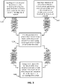
- Fig. 3 shows a flow chart according to a computer-implemented method of an embodiment of the present disclosure.
- Fig. 3 shows a flow chart of a computer-implemented method according to an embodiment of the present disclosure.
- a first set of sensor-based data e.g. radar-based data or LiDAR-based data
- a first Cartesian grid having a first spatial dimension and a first spatial resolution is input into a first branch (also referred to as head) of the deep neural network.
- a second set of sensor-based data for a second Cartesian grid having a second spatial dimension and a second spatial resolution is input into a second branch of the deep neural network.
- the first set of sensor-based data and the second set of sensor-based data are sensor-based data of the surrounding of the vehicle.
- the first spatial dimension is different from the second spatial dimension and the first spatial resolution is different from the second spatial resolution
- the first set of sensor-based data and the second set of sensor-based data are generated from a set of acquired sensor data regarding the surrounding of the vehicle for different spatial resolutions and dimensions.
- the first set of sensor-based data and the second set of sensor-based data are generated from the same acquired sensor data
- the first set of sensor-based data and the second set of sensor-based data include an overlapping region in Cartesian space.
- the deep neural network employs an artificial neural network architecture having multiple layers of respective network nodes to progressively extract higher-level features from the inputted sensor-base data.
- the deep neural network may be a convolutional neural network using convolution operations rather than general matrix multiplication in one or more layers and may be provided with self-determined (self-learned) kernel functions or filter functions.
- the deep neural network may be trained on the basis of publicly available datasets such as the Waymo dataset (https://waymo.com/open/data/), the KITTI dataset (http://www.cvlibs.net/datasets/kitti/), the NuScenes dataset (https://www.nuscenes.org/), the PeRL dataset (http://robots.engin.umich.edu/SoftwareData/Ford), the Oxford RobotCar dataset (https://robotcar-dataset.robots.ox.ac.uk/datasets/) and the like, see also https://www.ingedata.net/blog/lidar-datasets which are available for both LiDAR-based data sets as well as radar-based data sets.
- the point clouds are converted into Cartesian grids with different spatial ranges and resolutions.
- the training data may be multiple sequences of data cubes recorded from road scenarios, as well as the manually labeled targets (also known as ground truth).
- the sequences may be cut into small chunks with a fixed length.
- the training data may be formatted as a tensor of size N ⁇ T ⁇ S ⁇ R ⁇ A ⁇ D, where N is the number of training samples (e.g. 50k) in which each training sample may include a set of bounding boxes, T is the length of chunk (e.g. 12 time stamps), S is the number of sensors (e.g. 4), R is number of range bins (e.g. 108), A is number of angle bins (e.g. 150), D is number of Doppler bins (e.g. 20).
- the neural network may take a certain number of training samples (also referred to as batch size, e.g. 1 or 4 or 16, dependent GPU memory availability of the like), calculate the outputs and the loss with respect to ground truth labels (i.e. a difference between the ground truth and the detection result), update network parameters by backpropagation of the loss, and iterate this process until all the N samples are used. This process is called an epoch (i.e. one cycle through the full training dataset).
- the neural network may be trained with multiple epochs, e.g. 10, to get a result that minimizes errors and maximizes accuracy.
- the above specific numerical values are examples for performing a training process of the neural network.
- step S130 in Fig. 3 an interaction is provided between the first branch of the deep neural network and the second branch of the deep neural network at an intermediate stage of the deep neural network.
- the intermediate stage may be provided after a predetermined number of layers in the deep neural network.
- the intermediate stage may be provided after a predetermined number of layers in the deep neural network have independently or separately processed the first set of sensor-based data and the second set of sensor-based data in the first branch and the second branch, respectively.
- the interaction at the intermediate stage of the deep neural network is provided to take into account, in further processing of subsequently layers of the deep neural network (i.e. processing of the deep neural network after the intermediate stage), respectively identified features up until the intermediate stage for an overlapping spatial region of the first and second spatial dimension.
- the overlapping region is a common spatial region of the first Cartesian grid and the second Cartesian grid, and may be a central spatial region around a vehicle, e.g. a [-40m, 40m] range by [-40m, 40m] range spatial region around a vehicle, as explained above.
- first features which have been identified by the first branch of the deep neural network at the level of the intermediate stage with regard to the first set of sensor-based data are taken into account in the further processing in the second branch of the deep neural network
- second features which have been identified by the second branch of the deep neural network at the level of the intermediate stage with regard to the second set of sensor-based data are taken into account in the further processing in the first branch of the deep neural network.
- the respective branches of the deep neural network therefore interact to incorporate features identified for different spatial dimension and resolution in the further processing of the deep neural network.
- a first output of the first branch of the deep neural network and a second output of the second branch of the deep neural network is then fused (output fusion) to detect an object in the surrounding of the vehicle, in particular also a property of the object in the surrounding of the vehicle. That is, while the respective first and second branches of the deep neural network, which may be independently trained on the basis of the publicly available training data, generate independent outputs including identified features of objects in the surrounding of the vehicle, the fusion of the identified features of the first and second outputs gathers identified feature information of an object from multiple spatial scales or resolutions to improve the accuracy of the final object detection.
- two sets of sensor-based data for Cartesian grids of different spatial resolution and different spatial dimension are used.
- the present disclosure is, however, not limited in that regard.
- three or more sets of sensor-based data for Cartesian grids of different spatial resolution and different spatial dimension may be generated from the same acquired sensor data and may thus be input into three or more independent branches of the deep neural network.
- the above described interaction may be performed between each two of the three (i.e. between branch 1 and branch 2, between branch 1 and branch 3, and between branch 2 and branch 3) or more branches at one or more intermediate stages.
- branch 1 and branch 2 i.e. between branch 1 and branch 2
- branch 3 or more branches at one or more intermediate stages.
- the output of the respective branches is fused to detect an object or a plurality of objects in the surrounding of the vehicle.
- the sensor-based data are radar data which may be acquired in a data cube representing angle and range data in polar coordinates as well as Doppler (range rate) data.
- the data cube may have 150 angle values (bins) and 108 range values (bins) in polar coordinates for each of 20 Doppler (range rate) values (bins).
- the acquisition unit 120 may be further configured to perform a conversion of the (range, angle) data values from polar coordinates into Cartesian coordinates, i.e. a conversion of the (range, angle) data values into Cartesian (X, Y) data values (bins), in particular so that a near range Cartesian (X, Y) grid having a spatial dimension of 80m by 80m and a spatial resolution of 0.5m/bin and a far range Cartesian (X, Y) grid having a spatial dimension of 160m by 160m and a spatial resolution of 1m/bin is generated, each for a plurality Doppler (range rate) values (bins).
- range rate range rate
- the far range radar-based data values and the near range radar-based data values are input into respective independent branches of a convolutional neural network having a plurality of layers. Then, at an intermediate stage of the convolutional neural network, an interaction is provided between the first branch and the second branch of the convolutional neural network to provide, for the overlapping region of the near and far range grid, a fusion or combination of features identified by the respective branches of the convolutional neural network on the different spatial dimensions and resolutions.
- a feature may be considered as a feature value at every grid cell output at the intermediate stage. That is, each output of the convolutional neural network may be considered as a 2D feature map, here for each of the near range and the far range, and for each of a plurality of channels (for example, 64 channels in Fig. 4 ).
- feature maps refer to multiple 2-D grids, every grid encoding an aspect of data. For example, a color image with RGB channels can be considered as feature maps with 3 channels.
- the fusion of features means a concatenation of feature maps from different branches and a reduction of number of channels, so that the identified features of the first branch (with regard to the far range grid) are subsequently taken into account in the second branch (with regard to the near range grid) of the convolutional network and vice versa.
- the first and second output of the convolutional neural network may include detected object properties such as a target class, a bounding box, a size of an object, a position of the object, an orientation of an object, and/or a speed of an object (based on the Doppler data). It is noted that the position and the size of the object may be derived from the bounding box.
- the first output of the convolutional neural network may identify a bounding box for a car, a pedestrian, and a bus, while the second output of the convolutional neural network may identify the pedestrian and the bus (but not the car since the car is not located in the near range grid).
- a subsequent fusion of the first and second output of the convolutional neural network may be done, for example based on clustering bounding boxes, to verify whether the object(s) (such as the bus) is detected in both outputs and/or to use a statistical analysis for both the first and second output to provide a final output with regard to the detected object(s) while a statistical measure with regard to the differences of the first and second output may be optimized to improve the accuracy of object detection.
- object(s) such as the bus
- the interaction S130 may be further provided by re-sampling a first intermediate output (e.g. a first feature map) of the first branch at the intermediate stage and by re-sampling a second intermediate output (e.g. a second feature map) of the second branch at the intermediate stage.
- a first intermediate output e.g. a first feature map
- a second intermediate output e.g. a second feature map
- the respective intermediate outputs are outputs after the predetermined number of layers in the deep or convolutional neural network.
- Re-sampling may be performed by matching the spatial resolution of the first intermediate output to the second intermediate output. This re-sampling improved the interaction, as a more efficient and simple fusion of respective outputs is achieved.
- FIG. 5 An embodiment of the re-sampling of the first intermediate output is shown in Fig. 5 .
- the intermediate output of the first branch with regard to the far range grid, having 160 by 160 feature values in a spatial range of [-160m, 160m], for example, the overlapping spatial region of [-80m, 80m] may be cropped to 80 by 80 feature values in the overlapping spatial region and subsequently up-sampled to 160 by 160 feature values for the overlapping region.
- This up-sampled first intermediate output may be easily merged or fused (by concatenation and/or reduction, as will be explained below) with the second intermediate output of the second branch.
- FIG. 6 An embodiment of the re-sampling of the second intermediate output is shown in Fig. 6 .
- the intermediate output of the second branch with regard to the near range grid, having 160 by 160 feature values in a spatial range of [-80m,80m] is down-sampled to 80 by 80 feature values having a spatial resolution that matches the spatial resolution of the first intermediate output.
- the down-sampled second intermediate output may be easily merged or fused (by concatenation and/or reduction, as will be explained below) with the first intermediate output of the first branch, in particular the cropped intermediate output of the first branch corresponding to the overlapping region.
- the interaction at the intermediate stage of the neural network further can be performed by merging the first intermediate output with the re-sampled second intermediate output and by merging the second intermediate output with the re-sampled first intermediate output.
- the merging may generate a first concatenation of the first intermediate output with the re-sampled second intermediate output and generate a second concatenation of the second intermediate output with the re-sampled first intermediate output.
- the merging may further include a reduction of the first concatenation to generate a first reduced output (as further illustrated for example in Fig. 6 ) and a reduction of the second concatenation to generate a second reduced output, wherein the first reduced output and the second reduced output is used in the processing of the subsequent layers of the deep neural network.
- the reduction may employ a kernel (e.g. a 1x1 kernel) to reduce the channels to the number of channels as output at the intermediate stage.
- a 1x1 kernel of the convolutional neural network is used to reduce the number of channels back from 128 to 64.
- the first reduced output or the second reduced output may then be used to replace a corresponding part of the first intermediate output or the second intermediate output.
- the corresponding part preferably refers to the overlapping region.
- the overlapping region in the first intermediate output (with regard to the far range Cartesian grid) is replaced by the reduced output of the interaction with regard to the near range Cartesian grid.
- the interaction at the intermediate stage thus introduces features independently recognized by the first and second branches of the neural network into the corresponding other branch of the neural network, providing the capability to take into account feature detection at different spatial resolution in all subsequent layers of the neural network in both the first and second branch.
- the first and second branch also perform independent data processing after the intermediate stage to generate independent outputs, there is a mixing of feature detection for different spatial dimensions and resolutions ate the intermediate stage of the neural network. This not only provides a more efficient data representation (as explained above) but also an improved accuracy of object detection.
- the feature maps may also be referred to as feature fusion. That is, as multiple grids of different spatial dimension and resolution are processed separately by a convolutional or deep neural network, this produces some intermediate feature maps at the intermediate stage. Without loss of generality, the feature maps have the same spatial resolution as the input grids. As in Figs. 5 and 6 , the feature maps from different ranges have an overlapping region which may be the center region. In this overlapping region, multiple feature maps are available which may therefore be fused. For example, the center part of the far-range feature map may be up-sampled and merged with the short-range feature map. At the same time, the short-range feature map may be down-sampled to merge with the center part of the far-range feature map. The merge operation can be implemented by a concatenation and reduction which are common in deep neural networks.
- each grid after further independent processing of each branch of the neural network after the intermediate stage, each grid generates a set of final outputs, e.g. bounding box and class label of targets, segmentation mask of a scene and the like.
- the fusing S140 of the first output (final output) of the first branch of the deep neural network and the second output (final output) of the second branch of the deep neural network may further include a filtering out of overlapping one or more bounding boxes.
- a traditional non-maximum suppression (NMS) may be used to filter out overlapping ones.
- NMS non-maximum suppression
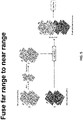
- the fusing S140 of the first output (final output) of the first branch of the deep neural network and the second output (final output) of the second branch of the deep neural network may also further include a prioritizing of information from the first output or the second output by using range information. For example, small objects such as pedestrians are detected more accurately from the short-range, therefore a higher confidence may be associated to a pedestrian bounding box. For a segmentation output, segmentation masks may be resampled into the same resolution and may then be added. Similarly, range prior can be used to perform a weighted sum.
- a statistical analysis may provide more statistical weight to the output information of the near range Cartesian grid as compared to the output information of the far range Cartesian grid.
- the computer-implemented method described above may be stored as a computer program in the memory 410 of a computer 400, which may be a board computer of the vehicle, a computer of a device, radar sensor, radar system, LiDAR sensor, LiDAR system or the like and may be executed by a processor 420 of the computer 400 as shown in Fig. 7 .
Landscapes
- Engineering & Computer Science (AREA)
- Physics & Mathematics (AREA)
- Remote Sensing (AREA)
- Radar, Positioning & Navigation (AREA)
- General Physics & Mathematics (AREA)
- Computer Networks & Wireless Communication (AREA)
- Theoretical Computer Science (AREA)
- Electromagnetism (AREA)
- Evolutionary Computation (AREA)
- Artificial Intelligence (AREA)
- Data Mining & Analysis (AREA)
- Computing Systems (AREA)
- General Engineering & Computer Science (AREA)
- Health & Medical Sciences (AREA)
- Life Sciences & Earth Sciences (AREA)
- General Health & Medical Sciences (AREA)
- Software Systems (AREA)
- Multimedia (AREA)
- Computer Vision & Pattern Recognition (AREA)
- Biophysics (AREA)
- Biomedical Technology (AREA)
- Molecular Biology (AREA)
- Mathematical Physics (AREA)
- Computational Linguistics (AREA)
- Bioinformatics & Computational Biology (AREA)
- Evolutionary Biology (AREA)
- Bioinformatics & Cheminformatics (AREA)
- Databases & Information Systems (AREA)
- Medical Informatics (AREA)
- Traffic Control Systems (AREA)
- Optical Radar Systems And Details Thereof (AREA)
- Image Analysis (AREA)
- Radar Systems Or Details Thereof (AREA)
Applications Claiming Priority (1)
| Application Number | Priority Date | Filing Date | Title |
|---|---|---|---|
| GB2101445.1A GB2603476A (en) | 2021-02-02 | 2021-02-02 | Object detection with multiple ranges and resolutions |
Publications (1)
| Publication Number | Publication Date |
|---|---|
| EP4036595A1 true EP4036595A1 (de) | 2022-08-03 |
Family
ID=74865417
Family Applications (1)
| Application Number | Title | Priority Date | Filing Date |
|---|---|---|---|
| EP22154478.6A Pending EP4036595A1 (de) | 2021-02-02 | 2022-02-01 | Objektdetektion mit mehreren bereichen und auflösungen |
Country Status (4)
| Country | Link |
|---|---|
| US (1) | US12535585B2 (de) |
| EP (1) | EP4036595A1 (de) |
| CN (1) | CN114839628A (de) |
| GB (1) | GB2603476A (de) |
Families Citing this family (3)
| Publication number | Priority date | Publication date | Assignee | Title |
|---|---|---|---|---|
| US12535573B2 (en) | 2022-01-04 | 2026-01-27 | Aptiv Technologies AG | Interleaving radar range and doppler processing |
| CN114708332B (zh) * | 2022-03-07 | 2025-07-08 | 北京鉴智科技有限公司 | 基于透视投影的图像处理方法、装置及电子设备 |
| DE102023201259A1 (de) * | 2023-02-15 | 2024-08-22 | Robert Bosch Gesellschaft mit beschränkter Haftung | Vorrichtung und Verfahren zur Verarbeitung von Sensordaten, Sensorsystem |
Citations (4)
| Publication number | Priority date | Publication date | Assignee | Title |
|---|---|---|---|---|
| US7639171B2 (en) | 2007-09-27 | 2009-12-29 | Delphi Technologies, Inc. | Radar system and method of digital beamforming |
| US9470777B2 (en) | 2014-09-19 | 2016-10-18 | Delphi Technologies, Inc. | Radar system for automated vehicle with phase change based target catagorization |
| EP3454079A1 (de) | 2017-09-12 | 2019-03-13 | Aptiv Technologies Limited | Verfahren zur bestimmung der angemessenheit eines radarziels als ein positionsorientierungspunkt |
| WO2020113160A2 (en) * | 2018-11-30 | 2020-06-04 | Qualcomm Incorporated | Radar deep learning |
Family Cites Families (11)
| Publication number | Priority date | Publication date | Assignee | Title |
|---|---|---|---|---|
| GB0912449D0 (en) | 2009-07-17 | 2009-08-26 | Rasmussen O B | Method of an apparatus for manufacture of a laminate comprising an oriented and fine-waved film, and resultant products |
| US10339421B2 (en) * | 2017-03-30 | 2019-07-02 | Toyota Motor Engineering & Manufacturing North America, Inc. | RGB-D scene labeling with multimodal recurrent neural networks |
| US10404261B1 (en) * | 2018-06-01 | 2019-09-03 | Yekutiel Josefsberg | Radar target detection system for autonomous vehicles with ultra low phase noise frequency synthesizer |
| CN109460737A (zh) * | 2018-11-13 | 2019-03-12 | 四川大学 | 一种基于增强式残差神经网络的多模态语音情感识别方法 |
| US11276189B2 (en) * | 2019-03-06 | 2022-03-15 | Qualcomm Incorporated | Radar-aided single image three-dimensional depth reconstruction |
| CN110210389B (zh) | 2019-05-31 | 2022-07-19 | 东南大学 | 一种面向道路交通场景的多目标识别跟踪方法 |
| US11214261B2 (en) * | 2019-06-11 | 2022-01-04 | GM Global Technology Operations LLC | Learn association for multi-object tracking with multi sensory data and missing modalities |
| CN110956094B (zh) * | 2019-11-09 | 2023-12-01 | 北京工业大学 | 一种基于非对称双流网络的rgb-d多模态融合人员检测方法 |
| CN111309906A (zh) | 2020-02-09 | 2020-06-19 | 北京工业大学 | 基于集成神经网络的长短混合型文本分类优化方法 |
| KR102270827B1 (ko) * | 2020-02-21 | 2021-06-29 | 한양대학교 산학협력단 | 360도 주변 물체 검출 및 인식 작업을 위한 다중 센서 데이터 기반의 융합 정보 생성 방법 및 장치 |
| WO2022139783A1 (en) * | 2020-12-21 | 2022-06-30 | Intel Corporation | High end imaging radar |
-
2021
- 2021-02-02 GB GB2101445.1A patent/GB2603476A/en not_active Withdrawn
-
2022
- 2022-01-30 CN CN202210114004.7A patent/CN114839628A/zh active Pending
- 2022-02-01 US US17/649,666 patent/US12535585B2/en active Active
- 2022-02-01 EP EP22154478.6A patent/EP4036595A1/de active Pending
Patent Citations (4)
| Publication number | Priority date | Publication date | Assignee | Title |
|---|---|---|---|---|
| US7639171B2 (en) | 2007-09-27 | 2009-12-29 | Delphi Technologies, Inc. | Radar system and method of digital beamforming |
| US9470777B2 (en) | 2014-09-19 | 2016-10-18 | Delphi Technologies, Inc. | Radar system for automated vehicle with phase change based target catagorization |
| EP3454079A1 (de) | 2017-09-12 | 2019-03-13 | Aptiv Technologies Limited | Verfahren zur bestimmung der angemessenheit eines radarziels als ein positionsorientierungspunkt |
| WO2020113160A2 (en) * | 2018-11-30 | 2020-06-04 | Qualcomm Incorporated | Radar deep learning |
Also Published As
| Publication number | Publication date |
|---|---|
| CN114839628A (zh) | 2022-08-02 |
| GB2603476A (en) | 2022-08-10 |
| GB202101445D0 (en) | 2021-03-17 |
| US20220244383A1 (en) | 2022-08-04 |
| US12535585B2 (en) | 2026-01-27 |
Similar Documents
| Publication | Publication Date | Title |
|---|---|---|
| Cong et al. | Underwater robot sensing technology: A survey | |
| US11315271B2 (en) | Point cloud intensity completion method and system based on semantic segmentation | |
| US11556745B2 (en) | System and method for ordered representation and feature extraction for point clouds obtained by detection and ranging sensor | |
| Major et al. | Vehicle detection with automotive radar using deep learning on range-azimuth-doppler tensors | |
| KR20220155559A (ko) | 이미지 세그멘테이션을 이용한 자율 운항 방법 | |
| EP4036595A1 (de) | Objektdetektion mit mehreren bereichen und auflösungen | |
| KR102466804B1 (ko) | 이미지 세그멘테이션을 이용한 자율 운항 방법 | |
| Cui et al. | 3D detection and tracking for on-road vehicles with a monovision camera and dual low-cost 4D mmWave radars | |
| CN112379674B (zh) | 一种自动驾驶设备及系统 | |
| CN108303988A (zh) | 一种无人船的目标识别追踪系统及其工作方法 | |
| US11827238B2 (en) | Computing architecture of an autonomous vehicle | |
| KR101628155B1 (ko) | Ccl을 이용한 실시간 미확인 다중 동적물체 탐지 및 추적 방법 | |
| CN117808689A (zh) | 基于毫米波雷达与摄像头融合的深度补全方法 | |
| GB2573635A (en) | Object detection system and method | |
| CN115965847B (zh) | 交叉视角下多模态特征融合的三维目标检测方法和系统 | |
| CN207908979U (zh) | 一种无人船的目标识别追踪系统 | |
| EP3764124A1 (de) | Entfernungsmessvorrichtung, verfahren zur messung einer entfernung, fahrzeugvorrichtung und mobiles objekt | |
| Chetan et al. | An overview of recent progress of lane detection for autonomous driving | |
| CN113988197B (zh) | 基于多相机、多激光雷达的联合标定及目标融合检测方法 | |
| CN112651405B (zh) | 目标检测方法及装置 | |
| CN113688738A (zh) | 一种基于激光雷达点云数据的目标识别系统及方法 | |
| WO2023009180A1 (en) | Lidar-based object tracking | |
| CN114384486A (zh) | 一种数据处理方法及装置 | |
| CN115421160A (zh) | 路沿检测方法、装置、设备、车辆及存储介质 | |
| US20220269921A1 (en) | Motion Compensation and Refinement in Recurrent Neural Networks |
Legal Events
| Date | Code | Title | Description |
|---|---|---|---|
| PUAI | Public reference made under article 153(3) epc to a published international application that has entered the european phase |
Free format text: ORIGINAL CODE: 0009012 |
|
| STAA | Information on the status of an ep patent application or granted ep patent |
Free format text: STATUS: THE APPLICATION HAS BEEN PUBLISHED |
|
| AK | Designated contracting states |
Kind code of ref document: A1 Designated state(s): AL AT BE BG CH CY CZ DE DK EE ES FI FR GB GR HR HU IE IS IT LI LT LU LV MC MK MT NL NO PL PT RO RS SE SI SK SM TR |
|
| STAA | Information on the status of an ep patent application or granted ep patent |
Free format text: STATUS: REQUEST FOR EXAMINATION WAS MADE |
|
| 17P | Request for examination filed |
Effective date: 20230113 |
|
| RBV | Designated contracting states (corrected) |
Designated state(s): AL AT BE BG CH CY CZ DE DK EE ES FI FR GB GR HR HU IE IS IT LI LT LU LV MC MK MT NL NO PL PT RO RS SE SI SK SM TR |
|
| RAP3 | Party data changed (applicant data changed or rights of an application transferred) |
Owner name: APTIV TECHNOLOGIES LIMITED |
|
| RAP1 | Party data changed (applicant data changed or rights of an application transferred) |
Owner name: APTIV TECHNOLOGIES AG |
|
| RAP3 | Party data changed (applicant data changed or rights of an application transferred) |
Owner name: APTIV TECHNOLOGIES AG |
|
| STAA | Information on the status of an ep patent application or granted ep patent |
Free format text: STATUS: EXAMINATION IS IN PROGRESS |
|
| 17Q | First examination report despatched |
Effective date: 20241211 |