EP4036507B1 - Plate-fin heat exchanger and refrigeration system using same - Google Patents
Plate-fin heat exchanger and refrigeration system using same Download PDFInfo
- Publication number
- EP4036507B1 EP4036507B1 EP21203587.7A EP21203587A EP4036507B1 EP 4036507 B1 EP4036507 B1 EP 4036507B1 EP 21203587 A EP21203587 A EP 21203587A EP 4036507 B1 EP4036507 B1 EP 4036507B1
- Authority
- EP
- European Patent Office
- Prior art keywords
- flow channel
- plate
- header
- fin
- region
- Prior art date
- Legal status (The legal status is an assumption and is not a legal conclusion. Google has not performed a legal analysis and makes no representation as to the accuracy of the status listed.)
- Active
Links
Images




Classifications
-
- F—MECHANICAL ENGINEERING; LIGHTING; HEATING; WEAPONS; BLASTING
- F28—HEAT EXCHANGE IN GENERAL
- F28D—HEAT-EXCHANGE APPARATUS, NOT PROVIDED FOR IN ANOTHER SUBCLASS, IN WHICH THE HEAT-EXCHANGE MEDIA DO NOT COME INTO DIRECT CONTACT
- F28D9/00—Heat-exchange apparatus having stationary plate-like or laminated conduit assemblies for both heat-exchange media, the media being in contact with different sides of a conduit wall
- F28D9/0031—Heat-exchange apparatus having stationary plate-like or laminated conduit assemblies for both heat-exchange media, the media being in contact with different sides of a conduit wall the conduits for one heat-exchange medium being formed by paired plates touching each other
- F28D9/0043—Heat-exchange apparatus having stationary plate-like or laminated conduit assemblies for both heat-exchange media, the media being in contact with different sides of a conduit wall the conduits for one heat-exchange medium being formed by paired plates touching each other the plates having openings therein for circulation of at least one heat-exchange medium from one conduit to another
- F28D9/005—Heat-exchange apparatus having stationary plate-like or laminated conduit assemblies for both heat-exchange media, the media being in contact with different sides of a conduit wall the conduits for one heat-exchange medium being formed by paired plates touching each other the plates having openings therein for circulation of at least one heat-exchange medium from one conduit to another the plates having openings therein for both heat-exchange media
-
- F—MECHANICAL ENGINEERING; LIGHTING; HEATING; WEAPONS; BLASTING
- F28—HEAT EXCHANGE IN GENERAL
- F28D—HEAT-EXCHANGE APPARATUS, NOT PROVIDED FOR IN ANOTHER SUBCLASS, IN WHICH THE HEAT-EXCHANGE MEDIA DO NOT COME INTO DIRECT CONTACT
- F28D1/00—Heat-exchange apparatus having stationary conduit assemblies for one heat-exchange medium only, the media being in contact with different sides of the conduit wall, in which the other heat-exchange medium is a large body of fluid, e.g. domestic or motor car radiators
- F28D1/02—Heat-exchange apparatus having stationary conduit assemblies for one heat-exchange medium only, the media being in contact with different sides of the conduit wall, in which the other heat-exchange medium is a large body of fluid, e.g. domestic or motor car radiators with heat-exchange conduits immersed in the body of fluid
- F28D1/03—Heat-exchange apparatus having stationary conduit assemblies for one heat-exchange medium only, the media being in contact with different sides of the conduit wall, in which the other heat-exchange medium is a large body of fluid, e.g. domestic or motor car radiators with heat-exchange conduits immersed in the body of fluid with plate-like or laminated conduits
- F28D1/0308—Heat-exchange apparatus having stationary conduit assemblies for one heat-exchange medium only, the media being in contact with different sides of the conduit wall, in which the other heat-exchange medium is a large body of fluid, e.g. domestic or motor car radiators with heat-exchange conduits immersed in the body of fluid with plate-like or laminated conduits the conduits being formed by paired plates touching each other
- F28D1/0325—Heat-exchange apparatus having stationary conduit assemblies for one heat-exchange medium only, the media being in contact with different sides of the conduit wall, in which the other heat-exchange medium is a large body of fluid, e.g. domestic or motor car radiators with heat-exchange conduits immersed in the body of fluid with plate-like or laminated conduits the conduits being formed by paired plates touching each other the plates having lateral openings therein for circulation of the heat-exchange medium from one conduit to another
- F28D1/0333—Heat-exchange apparatus having stationary conduit assemblies for one heat-exchange medium only, the media being in contact with different sides of the conduit wall, in which the other heat-exchange medium is a large body of fluid, e.g. domestic or motor car radiators with heat-exchange conduits immersed in the body of fluid with plate-like or laminated conduits the conduits being formed by paired plates touching each other the plates having lateral openings therein for circulation of the heat-exchange medium from one conduit to another the plates having integrated connecting members
- F28D1/0341—Heat-exchange apparatus having stationary conduit assemblies for one heat-exchange medium only, the media being in contact with different sides of the conduit wall, in which the other heat-exchange medium is a large body of fluid, e.g. domestic or motor car radiators with heat-exchange conduits immersed in the body of fluid with plate-like or laminated conduits the conduits being formed by paired plates touching each other the plates having lateral openings therein for circulation of the heat-exchange medium from one conduit to another the plates having integrated connecting members with U-flow or serpentine-flow inside the conduits
-
- F—MECHANICAL ENGINEERING; LIGHTING; HEATING; WEAPONS; BLASTING
- F25—REFRIGERATION OR COOLING; COMBINED HEATING AND REFRIGERATION SYSTEMS; HEAT PUMP SYSTEMS; MANUFACTURE OR STORAGE OF ICE; LIQUEFACTION SOLIDIFICATION OF GASES
- F25B—REFRIGERATION MACHINES, PLANTS OR SYSTEMS; COMBINED HEATING AND REFRIGERATION SYSTEMS; HEAT PUMP SYSTEMS
- F25B39/00—Evaporators; Condensers
-
- F—MECHANICAL ENGINEERING; LIGHTING; HEATING; WEAPONS; BLASTING
- F28—HEAT EXCHANGE IN GENERAL
- F28D—HEAT-EXCHANGE APPARATUS, NOT PROVIDED FOR IN ANOTHER SUBCLASS, IN WHICH THE HEAT-EXCHANGE MEDIA DO NOT COME INTO DIRECT CONTACT
- F28D1/00—Heat-exchange apparatus having stationary conduit assemblies for one heat-exchange medium only, the media being in contact with different sides of the conduit wall, in which the other heat-exchange medium is a large body of fluid, e.g. domestic or motor car radiators
- F28D1/02—Heat-exchange apparatus having stationary conduit assemblies for one heat-exchange medium only, the media being in contact with different sides of the conduit wall, in which the other heat-exchange medium is a large body of fluid, e.g. domestic or motor car radiators with heat-exchange conduits immersed in the body of fluid
- F28D1/04—Heat-exchange apparatus having stationary conduit assemblies for one heat-exchange medium only, the media being in contact with different sides of the conduit wall, in which the other heat-exchange medium is a large body of fluid, e.g. domestic or motor car radiators with heat-exchange conduits immersed in the body of fluid with tubular conduits
- F28D1/053—Heat-exchange apparatus having stationary conduit assemblies for one heat-exchange medium only, the media being in contact with different sides of the conduit wall, in which the other heat-exchange medium is a large body of fluid, e.g. domestic or motor car radiators with heat-exchange conduits immersed in the body of fluid with tubular conduits the conduits being straight
- F28D1/0535—Heat-exchange apparatus having stationary conduit assemblies for one heat-exchange medium only, the media being in contact with different sides of the conduit wall, in which the other heat-exchange medium is a large body of fluid, e.g. domestic or motor car radiators with heat-exchange conduits immersed in the body of fluid with tubular conduits the conduits being straight the conduits having a non-circular cross-section
- F28D1/05358—Assemblies of conduits connected side by side or with individual headers, e.g. section type radiators
-
- F—MECHANICAL ENGINEERING; LIGHTING; HEATING; WEAPONS; BLASTING
- F28—HEAT EXCHANGE IN GENERAL
- F28F—DETAILS OF HEAT-EXCHANGE AND HEAT-TRANSFER APPARATUS, OF GENERAL APPLICATION
- F28F1/00—Tubular elements; Assemblies of tubular elements
- F28F1/02—Tubular elements of cross-section which is non-circular
- F28F1/025—Tubular elements of cross-section which is non-circular with variable shape, e.g. with modified tube ends, with different geometrical features
-
- F—MECHANICAL ENGINEERING; LIGHTING; HEATING; WEAPONS; BLASTING
- F28—HEAT EXCHANGE IN GENERAL
- F28F—DETAILS OF HEAT-EXCHANGE AND HEAT-TRANSFER APPARATUS, OF GENERAL APPLICATION
- F28F21/00—Constructions of heat-exchange apparatus characterised by the selection of particular materials
- F28F21/08—Constructions of heat-exchange apparatus characterised by the selection of particular materials of metal
- F28F21/081—Heat exchange elements made from metals or metal alloys
- F28F21/084—Heat exchange elements made from metals or metal alloys from aluminium or aluminium alloys
-
- F—MECHANICAL ENGINEERING; LIGHTING; HEATING; WEAPONS; BLASTING
- F28—HEAT EXCHANGE IN GENERAL
- F28F—DETAILS OF HEAT-EXCHANGE AND HEAT-TRANSFER APPARATUS, OF GENERAL APPLICATION
- F28F3/00—Plate-like or laminated elements; Assemblies of plate-like or laminated elements
- F28F3/02—Elements or assemblies thereof with means for increasing heat-transfer area, e.g. with fins, with recesses, with corrugations
- F28F3/04—Elements or assemblies thereof with means for increasing heat-transfer area, e.g. with fins, with recesses, with corrugations the means being integral with the element
- F28F3/048—Elements or assemblies thereof with means for increasing heat-transfer area, e.g. with fins, with recesses, with corrugations the means being integral with the element in the form of ribs integral with the element or local variations in thickness of the element, e.g. grooves, microchannels
-
- F—MECHANICAL ENGINEERING; LIGHTING; HEATING; WEAPONS; BLASTING
- F28—HEAT EXCHANGE IN GENERAL
- F28F—DETAILS OF HEAT-EXCHANGE AND HEAT-TRANSFER APPARATUS, OF GENERAL APPLICATION
- F28F9/00—Casings; Header boxes; Auxiliary supports for elements; Auxiliary members within casings
- F28F9/02—Header boxes; End plates
- F28F9/0219—Arrangements for sealing end plates into casing or header box; Header box sub-elements
- F28F9/0221—Header boxes or end plates formed by stacked elements
-
- F—MECHANICAL ENGINEERING; LIGHTING; HEATING; WEAPONS; BLASTING
- F28—HEAT EXCHANGE IN GENERAL
- F28F—DETAILS OF HEAT-EXCHANGE AND HEAT-TRANSFER APPARATUS, OF GENERAL APPLICATION
- F28F9/00—Casings; Header boxes; Auxiliary supports for elements; Auxiliary members within casings
- F28F9/02—Header boxes; End plates
- F28F9/04—Arrangements for sealing elements into header boxes or end plates
- F28F9/16—Arrangements for sealing elements into header boxes or end plates by permanent joints, e.g. by rolling
- F28F9/18—Arrangements for sealing elements into header boxes or end plates by permanent joints, e.g. by rolling by welding
- F28F9/182—Arrangements for sealing elements into header boxes or end plates by permanent joints, e.g. by rolling by welding the heat-exchange conduits having ends with a particular shape, e.g. deformed; the heat-exchange conduits or end plates having supplementary joining means, e.g. abutments
-
- F—MECHANICAL ENGINEERING; LIGHTING; HEATING; WEAPONS; BLASTING
- F28—HEAT EXCHANGE IN GENERAL
- F28D—HEAT-EXCHANGE APPARATUS, NOT PROVIDED FOR IN ANOTHER SUBCLASS, IN WHICH THE HEAT-EXCHANGE MEDIA DO NOT COME INTO DIRECT CONTACT
- F28D21/00—Heat-exchange apparatus not covered by any of the groups F28D1/00 - F28D20/00
- F28D2021/0019—Other heat exchangers for particular applications; Heat exchange systems not otherwise provided for
- F28D2021/0068—Other heat exchangers for particular applications; Heat exchange systems not otherwise provided for for refrigerant cycles
-
- F—MECHANICAL ENGINEERING; LIGHTING; HEATING; WEAPONS; BLASTING
- F28—HEAT EXCHANGE IN GENERAL
- F28F—DETAILS OF HEAT-EXCHANGE AND HEAT-TRANSFER APPARATUS, OF GENERAL APPLICATION
- F28F2255/00—Heat exchanger elements made of materials having special features or resulting from particular manufacturing processes
- F28F2255/16—Heat exchanger elements made of materials having special features or resulting from particular manufacturing processes extruded
Definitions
- the present disclosure relates to a plate-fin heat exchanger and a refrigeration system using the plate-fin heat exchanger.
- the plate-fin heat exchanger includes a plurality of plate fins layered with a gap therebetween.
- Each of the plate fins includes a first header flow channel, a second header flow channel, and a heat transfer flow channel.
- the plate fin includes a pair of plates which are brazed to face each other.
- the plate fin allows a first fluid such as a refrigerant to flow from the first header flow channel to the second header flow channel via the heat transfer flow channel, and promotes heat exchange between the first fluid flowing through the heat transfer flow channel and a second fluid such as air flowing through a gap between the plate fins.
- US 4 846 268 A discloses a plate-fin heat exchanger according to the preamble of claim 1 and describes a heat exchanger comprising a multiplicity of longitudinally extending flattened tube structures disposed in a longitudinal coextensive array with fin structures bonded in abutting relation between adjacent pairs of tube structures.
- First and second header assemblies are connected with first and second end portions respectively of each tube structure and provide a fluid inlet for receiving a first fluid for passage through the tube structures during the passage of a second fluid through the fin structures. The first fluid passes from the second header assembly through a fluid outlet.
- Each header assembly is formed of a series of interconnected header structures, each of which comprises a pair of sheet metal plates formed to provide first marginal edge portions sealingly fixed in abutting relation with the exterior periphery of the associated tube structure end portion and wall portions spaced in a direction perpendicular to the longitudinal direction of extent of the tube structures having aligned openings therein.
- the remainder of the marginal edge portions of the plates are sealingly fixed in abutting engagement which together with the first marginal edge portions surround the openings and define with the spaced portions an enclosed first fluid containing volume communicating the interior of the associated tube structure end portion with the openings.
- Each spaced portion of each pair of sheet metal plates is sealingly fixed to a spaced portion of an adjacent pair of sheet metal plates along peripheries defining the openings therein.
- the present disclosure solves the problems caused by the conventional plate fin configuration, and provides a plate-fin heat exchanger that is lightweight and highly reliable and has high performance, and a refrigeration system using the plate-fin heat exchanger.
- a plate-fin heat exchanger is defined in appended claim 1. Among others, it includes a plate fin including a first header flow channel, a second header flow channel, and a heat transfer flow channel connected between the first and second header flow channels, the plate fin including a first header region having the first header flow channel, a second header region having the second header flow channel, and a flow channel region having the heat transfer flow channel, wherein the first and second header regions are each constituted by two joined plates each having a header flow channel opening, the flow channel region is constituted by a single flow channel plate in which the heat transfer flow channel is integrally formed, and the first and second header regions are integrally joined to the flow channel region.
- the flow channel region is constituted by a single plate in which the heat transfer flow channel is integrally formed due to the above configuration.
- the joining portions are located only in the first and second header regions, and thus, can be minimized. Therefore, the reliability of the heat exchanger is improved.
- the flow channel region constituted by a single plate has reduced weight and reduced thickness as compared with a flow channel region constituted by two joined plates. The reduction in thickness enables reduction in flow resistance of the second fluid flowing between the plate fins.
- a plate-fin heat exchanger which is highly reliable, is lightweight, and has high performance and a refrigeration system using the plate-fin heat exchanger are provided.
- each of plate fins of a plate-fin heat exchanger includes two plates brazed to face each other.
- Each plate includes a header flow channel opening and a recessed groove for a heat transfer flow channel.
- Such a plate fin is likely to cause a joining defect due to a large number of joining portions and the complexity of the flow channel configuration. Therefore, there is a problem that it is necessary to improve reliability by reducing joining defects.
- the plate fin since the plate fin includes two joined plates, the plate fin is large in thickness, so that a gap between the plate fins decreases. Therefore, there is also a problem that the flow resistance of a fluid flowing through the gap between the plate fins is increased to deteriorate heat exchange performance, and the weight of the entire heat exchanger increases.
- the present disclosure provides a plate-fin heat exchanger which is highly reliable, is lightweight, and has high performance and a refrigeration system using the plate-fin heat exchanger.
- FIGS. 1 to 8 A first exemplary embodiment will now be described with reference to FIGS. 1 to 8 .
- heat exchanger 1 includes plate-fin layered body 2, end plate 3a joined to an upper surface of plate-fin layered body 2, and end plate 3b joined to a lower surface of plate-fin layered body 2.
- Plate-fin layered body 2 is joined to and integrated with end plates 3a and 3b.
- End plates 3a and 3b have substantially the same shape as plate-fin layered body 2 in planar view.
- Heat exchanger 1 has tube 4 and tube 5 that are connected to end plate 3a.
- Tube 4 serves as an inlet when heat exchanger 1 is used as a condenser and serves as an outlet when heat exchanger 1 is used as an evaporator.
- tube 5 serves as an outlet when heat exchanger 1 is used as a condenser and serves as an inlet when heat exchanger 1 is used as an evaporator.
- End plates 3a and 3b on both sides of plate-fin layered body 2 are joined to plate-fin layered body 2 by brazing while sandwiching plate-fin layered body 2.
- End plates 3a and 3b are connected to each other at both ends in the longitudinal direction of end plates 3a and 3b by fastening means 7 to maintain rigidity as a heat exchanger.
- plate fin 2a has heat transfer flow channels 8 through which a first fluid (hereinafter referred to as a refrigerant) such as a refrigerant flows.
- a first fluid hereinafter referred to as a refrigerant
- a second fluid hereinafter referred to as air
- plate-fin layered body 2 promotes heat exchange between the refrigerant flowing through heat transfer flow channels 8 provided in plate fins 2a and air flowing through a gap formed between layered plate fins 2a.
- plate fin 2a includes first header region 11a, second header region 11b, and flow channel region 12.
- First header region 11a has first header flow channel 9 connected to tube 4.
- Second header region 11b has second header flow channel 10 connected to tube 5.
- Flow channel region 12 has heat transfer flow channels 8 connecting first header flow channel 9 and second header flow channel 10.
- First and second header regions 11a and 11b are integrally joined to flow channel region 12.
- First and second header regions 11a and 11b have substantially the same shape. First header region 11a will be described below. In order to avoid redundant description, the description of second header region 11b may be omitted.
- first header region 11a includes first plate 16a and second plate 16b that are brazed to face each other.
- First plate 16a includes header flow channel opening 9a (10a), ring-shaped recessed groove 13 formed in an outer periphery of header flow channel opening 9a, communication-path recessed groove 14 extending from ring-shaped recessed groove 13, and flow channel cover 15 connected to communication-path recessed groove 14.
- Second plate 16b has header flow channel opening 9a (10a) and ring-shaped recessed groove 13 formed in an outer periphery of header flow channel opening 9a.
- first header region 11a includes connection member 17 that connects first plate 16a and second plate 16b. Connection member 17 is bent, so that first plate 16a faces second plate 16b.
- heat transfer flow channels 8 of flow channel region 12 are extruded as a pair of two rows in this example.
- flow channel region 12 has protrusions 12c for allowing the air flowing through the gap between layered plate fins to meander on the back surfaces of fin portions 12b between heat transfer flow channel formation portions 12a.
- auxiliary communication flow paths 19 recessed in first and second header regions 11a and 11b, respectively, and turn back between first header flow channel 9 and second header flow channel 10.
- End plates 3a and 3b and plate fins 2a are made of aluminum or an aluminum alloy.
- heat exchanger 1 When heat exchanger 1 according to the present exemplary embodiment is used, for example, under a condensation condition, a refrigerant in a gas phase state flows into first header flow channels 9 on an inlet side of plate-fin layered body 2 through tube 4.
- the gas-phase refrigerant flowing into first header flow channels 9 flows while turning back through heat transfer flow channels 8 of plate fins 2a, and flows out through tube 5 to a refrigerant circuit of a refrigeration system via second header flow channels 10 on the outlet side.
- the gas-phase refrigerant sequentially transitions into a liquid phase by heat exchange with air passing through the gaps between layered plate fins while flowing through heat transfer flow channels 8.
- first and second header regions 11a and 11b each include two plates which are first plate 16a and second plate 16b and which are joined by brazing.
- Flow channel region 12 includes single flow channel plate 18 having heat transfer flow channels 8 formed therein by extrusion process. Therefore, in heat exchanger 1, the joining portions by brazing are located only in first and second header regions 11a and 11b, and thus can be minimized. Accordingly, the reliability of heat exchanger 1 can be significantly enhanced.
- flow channel region 12 of plate fin 2a is composed of single flow channel plate 18 having heat transfer flow channels 8 formed therein by extrusion process.
- the thickness of each fin portion 12b of flow channel region 12 is smaller than the total thickness of brazed first and second plates 16a and 16b of header region 11.
- each of heat transfer flow channel formation portions 12a of flow channel region 12 has thickness t.
- First and second header regions 11a and 11b each are constituted by joined first and second plates 16a and 16b, and have thickness T in communication -path recessed groove 14. Thickness T corresponds to a thickness of a portion having a conventional heat transfer flow channel formed by joining two plates. Thickness t is smaller than thickness T.
- gap L which is an air passage, between flow channel regions 12 of layered plate fins illustrated in FIG. 8 can be made wider as compared with a prior art.
- the flow resistance of air can be reduced, and the performance of heat exchanger 1 can be enhanced.
- heat exchanger 1 enables air to meander as indicated by dashed arrow Y by protrusions 12c protruding to gap L between flow channel regions 12 of layered plate fins, whereby the performance of heat exchanger 1 can be further enhanced.
- plate fin 2a is reduced in weight due to reduction in thickness of flow channel region 12. Therefore, the weight of entire heat exchanger 1 can be significantly reduced, whereby weight saving can be achieved.
- first header region 11a is connected to flow channel region 12 such that first end parts 12ab of heat transfer flow channel formation portions 12a are sandwiched between flow channel cover 15 provided in first plate 16a of first header region 11a and the flat surface portion of second plate 16b.
- second header region 11b is connected to flow channel region 12.
- first plate 16a and second plate 16b are connected by connection member 17.
- First plate 16a and second plate 16b are managed as one component, and thus, a number of components can be reduced, and parts management can be facilitated.
- flow channel region 12 is constituted by single flow channel plate 18 in which heat transfer flow channel 8 is integrally formed.
- the joining portions are located only in first and second header regions 11a and 11b. That is, the joining portions by brazing or the like can be minimized. Therefore, the reliability of heat exchanger 1 can be enhanced.
- Flow channel region 12 constituted by single flow channel plate 18 can reduce the flow resistance of the second fluid due to reduced weight and reduced thickness as compared with a flow channel region constituted by two joined plates. As a result, it is possible to provide a plate-fin heat exchanger that is lightweight, has high performance, and is highly reliable.
- the plate-fin heat exchanger includes plate fin 2a including first header flow channel 9, second header flow channel 10, and a plurality of heat transfer flow channels 8 connected in series between first and second header flow channels 9 and 10, plate fin 2a including header region 11 having first and second header flow channels 9 and 10, flow channel region 12 having the plurality of heat transfer flow channels 8, and auxiliary flow channel region 21 having communication path 20 connecting the plurality of heat transfer flow channels 8, wherein header region 11 is integrally joined to a first end of flow channel region 12, and auxiliary flow channel region 21 is integrally joined to a second end opposite to the first end of flow channel region 12.
- first and second header flow channels 9 and 10 are gathered near the first end of plate fin 2a of heat exchanger 1.
- the weight of the heat exchanger can be reduced, reliability and performance can be improved, and the work of connecting tubes of a refrigeration system to first and second header flow channels 9 and 10 can be facilitated.
- flow channel region 12 may have heat transfer flow channel formation portion 12a for forming heat transfer flow channel 8
- heat transfer flow channel formation portion 12a may have first end part 12ab and second end part 12ac opposite to the first end part, first end part 12ab may be sandwiched between two plates 16a and 16b of first header region 11a, and second end part 12ac may be sandwiched between two plates 16a and 16b of second header region 11b.
- first and second header regions 11a and 11b can be easily connected to flow channel region 12 by brazing, and the brazing can be made robust and secure.
- Flow channel region 12 may have a plurality of heat transfer flow channel formation portions 12a for forming the plurality of heat transfer flow channels 8, each of the plurality of heat transfer flow channel formation portions 12a may have first end part 12ab and second end part 12ac opposite to first end part 12ab, header region 11 may be constituted by two joined plates 16a and 16b, first end part 12ab of each of the plurality of heat transfer flow channel formation portions 12a may be sandwiched between two joined plates 16a and 16b of header region 11, auxiliary flow channel region 21 may be constituted by two joined plates 16a and 16b, and second end part 12ac of each of the plurality of heat transfer flow channel formation portions 12a may be sandwiched between two joined plates 16a and 16b of auxiliary flow channel region 21.
- header region 11 can be easily connected to flow channel region 12 by brazing, and the brazing can be made robust and secure.
- auxiliary flow channel region 21 and flow channel region 12 can be easily connected by brazing, and the brazing can be made robust and secure.
- FIG. 10 is a diagram illustrating a refrigeration cycle of an air conditioner equipped with the plate-fin heat exchanger according to the first exemplary embodiment
- FIG. 11 is a schematic sectional view illustrating an indoor unit of the air conditioner.
- the air conditioner includes outdoor unit 51 and indoor unit 52 connected to outdoor unit 51.
- Outdoor unit 51 is provided with compressor 53 for compressing a refrigerant, four-way valve 54 for switching a refrigerant circuit during cooling and heating operations, outdoor heat exchanger 55 that exchanges heat between the refrigerant and outdoor air, decompressor 56 for decompressing the refrigerant, and outdoor blower 59.
- Indoor unit 52 is provided with indoor heat exchanger 57 for exchanging heat between the refrigerant and indoor air, and indoor blower 58.
- Indoor heat exchanger 57 is the plate-fin heat exchanger described in the first exemplary embodiment.
- Compressor 53, four-way valve 54, indoor heat exchanger 57, decompressor 56, and outdoor heat exchanger 55 are connected via the refrigerant circuit to define a heat-pump refrigeration cycle.
- four-way valve 54 is switched such that the discharge side of compressor 53 and outdoor heat exchanger 55 communicate with each other.
- the refrigerant compressed by compressor 53 transitions into a high-temperature high-pressure gas-phase refrigerant and is supplied to outdoor heat exchanger 55 through four-way valve 54.
- the refrigerant dissipates heat by heat exchange with outdoor air to transition into a high-pressure liquid-phase refrigerant, and is supplied to decompressor 56.
- the refrigerant is decompressed by decompressor 56 into low-temperature low-pressure two-phase refrigerant, and supplied to indoor unit 52.
- the refrigerant enters indoor heat exchanger 57, absorbs heat by heat exchange with indoor air, and evaporates to transition into a low-temperature gas refrigerant. During this cycle, the indoor air is cooled, so that an indoor space is cooled. The refrigerant then returns to outdoor unit 51, and is returned back to compressor 53 through four-way valve 54.
- four-way valve 54 is switched such that the discharge side of compressor 53 and indoor unit 52 communicate with each other.
- the refrigerant compressed by compressor 53 transitions into a high-temperature high-pressure refrigerant, and is supplied to indoor unit 52 through four-way valve 54.
- the high-temperature high-pressure refrigerant enters indoor heat exchanger 57 and dissipates heat by heat exchange with indoor air to transition into a high-pressure liquid refrigerant.
- the indoor air is heated, so that the indoor space is heated.
- the refrigerant is supplied to decompressor 56, is decompressed by decompressor 56 to transition into a low-temperature low-pressure two-phase refrigerant, is sent to outdoor heat exchanger 55, evaporates by heat exchange with outdoor air, and then, returns to compressor 53 through four-way valve 54.
- the refrigeration system according to the present disclosure uses the heat exchanger described in the first exemplary embodiment as indoor heat exchanger 57, the refrigeration system is lightweight, has high performance, and is highly reliable.
- the present disclosure is not limited thereto, and various modifications, replacements, additions, omissions, and the like are possible.
- the first fluid is a refrigerant and the second fluid is air
- the present disclosure is not limited thereto.
- the air conditioner has been described above as the refrigeration system
- the refrigeration system may be a refrigerator, a refrigeration case, or a heat pump water heater using water as the second fluid. That is, the exemplary embodiments disclosed herein are illustrative in all respects and are not restrictive, and the scope of the present disclosure is defined by the claims.
- the present disclosure can provide a plate-fin heat exchanger that is lightweight and highly reliable and has high performance, and a refrigeration system using the plate-fin heat exchanger. Accordingly, the present disclosure is widely applicable to heat exchangers used in domestic and industrial air-conditioners, and various refrigerating devices, and thus, is of great industrial value.
Landscapes
- Engineering & Computer Science (AREA)
- Physics & Mathematics (AREA)
- Thermal Sciences (AREA)
- Mechanical Engineering (AREA)
- General Engineering & Computer Science (AREA)
- Geometry (AREA)
- Heat-Exchange Devices With Radiators And Conduit Assemblies (AREA)
Description
- The present disclosure relates to a plate-fin heat exchanger and a refrigeration system using the plate-fin heat exchanger.
-
PTL 1 discloses a plate-fin heat exchanger. The plate-fin heat exchanger includes a plurality of plate fins layered with a gap therebetween. Each of the plate fins includes a first header flow channel, a second header flow channel, and a heat transfer flow channel. The plate fin includes a pair of plates which are brazed to face each other. The plate fin allows a first fluid such as a refrigerant to flow from the first header flow channel to the second header flow channel via the heat transfer flow channel, and promotes heat exchange between the first fluid flowing through the heat transfer flow channel and a second fluid such as air flowing through a gap between the plate fins. -
US 4 846 268 A discloses a plate-fin heat exchanger according to the preamble ofclaim 1 and describes a heat exchanger comprising a multiplicity of longitudinally extending flattened tube structures disposed in a longitudinal coextensive array with fin structures bonded in abutting relation between adjacent pairs of tube structures. First and second header assemblies are connected with first and second end portions respectively of each tube structure and provide a fluid inlet for receiving a first fluid for passage through the tube structures during the passage of a second fluid through the fin structures. The first fluid passes from the second header assembly through a fluid outlet. Each header assembly is formed of a series of interconnected header structures, each of which comprises a pair of sheet metal plates formed to provide first marginal edge portions sealingly fixed in abutting relation with the exterior periphery of the associated tube structure end portion and wall portions spaced in a direction perpendicular to the longitudinal direction of extent of the tube structures having aligned openings therein. The remainder of the marginal edge portions of the plates are sealingly fixed in abutting engagement which together with the first marginal edge portions surround the openings and define with the spaced portions an enclosed first fluid containing volume communicating the interior of the associated tube structure end portion with the openings. Each spaced portion of each pair of sheet metal plates is sealingly fixed to a spaced portion of an adjacent pair of sheet metal plates along peripheries defining the openings therein. - Other plate-fin heat exchangers are described in
US 5 634 519 A ,US 6 467 536 B1 ,US 4 969 512 A ,US 2020/158388 A1 ,FR 2 864 215 A1CN 110 285 603 A andJP 2019 095161 A - PTL 1: Unexamined
Japanese Patent Publication No. 2018-66532 - The present disclosure solves the problems caused by the conventional plate fin configuration, and provides a plate-fin heat exchanger that is lightweight and highly reliable and has high performance, and a refrigeration system using the plate-fin heat exchanger.
- A plate-fin heat exchanger according to the present invention is defined in appended
claim 1. Among others, it includes a plate fin including a first header flow channel, a second header flow channel, and a heat transfer flow channel connected between the first and second header flow channels, the plate fin including a first header region having the first header flow channel, a second header region having the second header flow channel, and a flow channel region having the heat transfer flow channel, wherein the first and second header regions are each constituted by two joined plates each having a header flow channel opening, the flow channel region is constituted by a single flow channel plate in which the heat transfer flow channel is integrally formed, and the first and second header regions are integrally joined to the flow channel region. - In the plate-fin heat exchanger according to the present invention, the flow channel region is constituted by a single plate in which the heat transfer flow channel is integrally formed due to the above configuration. The joining portions are located only in the first and second header regions, and thus, can be minimized. Therefore, the reliability of the heat exchanger is improved. In addition, the flow channel region constituted by a single plate has reduced weight and reduced thickness as compared with a flow channel region constituted by two joined plates. The reduction in thickness enables reduction in flow resistance of the second fluid flowing between the plate fins. As described above, a plate-fin heat exchanger which is highly reliable, is lightweight, and has high performance and a refrigeration system using the plate-fin heat exchanger are provided.
-
-
FIG. 1 is an exploded perspective view illustrating an appearance of a plate-fin heat exchanger according to a first exemplary embodiment; -
FIG. 2 is a perspective view illustrating a part of a plate-fin layered body of the plate-fin heat exchanger; -
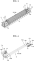
FIG. 3 is a perspective view illustrating an overall configuration of a plate fin of the plate-fin heat exchanger; -
FIG. 4 is a developed perspective view illustrating header regions of the plate fin of the plate-fin heat exchanger; -
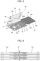
FIG. 5 is an enlarged perspective view of a main part of the plate fin of the plate-fin heat exchanger; -
FIG. 6 is a cross-sectional view taken along line A-A ofFIG. 2 ; -
FIG. 7 is an enlarged cross-sectional view of a main part ofFIG. 6 ; -
FIG. 8 is a cross-sectional view taken along line B-B ofFIG. 2 ; -
FIG. 9 is a perspective view illustrating a developed state, a completed state, and a layered state of plate fins in another exemplary embodiment not in accordance with the claimed invention; -
FIG. 10 is a diagram illustrating a refrigeration cycle of an air conditioner illustrated as an example of a refrigeration system using the plate-fin heat exchanger; and -
FIG. 11 is a cross-sectional view illustrating an indoor unit of the air conditioner. - As disclosed in
PTL 1, each of plate fins of a plate-fin heat exchanger includes two plates brazed to face each other. Each plate includes a header flow channel opening and a recessed groove for a heat transfer flow channel. Such a plate fin is likely to cause a joining defect due to a large number of joining portions and the complexity of the flow channel configuration. Therefore, there is a problem that it is necessary to improve reliability by reducing joining defects. Further, since the plate fin includes two joined plates, the plate fin is large in thickness, so that a gap between the plate fins decreases. Therefore, there is also a problem that the flow resistance of a fluid flowing through the gap between the plate fins is increased to deteriorate heat exchange performance, and the weight of the entire heat exchanger increases. - The inventors of the present disclosure have found that there are problems as described above, and arrived at the subject matter of the present disclosure in order to solve the problems.
- The present disclosure provides a plate-fin heat exchanger which is highly reliable, is lightweight, and has high performance and a refrigeration system using the plate-fin heat exchanger.
- Exemplary embodiments will be described in detail below with reference to the drawings. However, detailed descriptions more than necessary may be omitted. For example, a detailed description of well-known matters, and a duplicate description of substantially identical configurations may not be provided. This is to avoid an unnecessarily redundant description below and to facilitate understanding of a person skilled in the art.
- The accompanying drawings and the following description are provided to help those skilled in the art to fully understand the present disclosure and are not intended to limit the subject matter recited in the appended claims.
- A first exemplary embodiment will now be described with reference to
FIGS. 1 to 8 . - As illustrated in
FIG. 1 ,heat exchanger 1 according to the present exemplary embodiment includes plate-fin layeredbody 2, end plate 3a joined to an upper surface of plate-fin layeredbody 2, andend plate 3b joined to a lower surface of plate-fin layeredbody 2. Plate-fin layeredbody 2 is joined to and integrated withend plates 3a and 3b.End plates 3a and 3b have substantially the same shape as plate-fin layeredbody 2 in planar view.Heat exchanger 1 hastube 4 andtube 5 that are connected to end plate 3a. Tube 4 serves as an inlet whenheat exchanger 1 is used as a condenser and serves as an outlet whenheat exchanger 1 is used as an evaporator. Conversely,tube 5 serves as an outlet whenheat exchanger 1 is used as a condenser and serves as an inlet whenheat exchanger 1 is used as an evaporator. -
End plates 3a and 3b on both sides of plate-finlayered body 2 are joined to plate-finlayered body 2 by brazing while sandwiching plate-finlayered body 2.End plates 3a and 3b are connected to each other at both ends in the longitudinal direction ofend plates 3a and 3b by fastening means 7 to maintain rigidity as a heat exchanger. - As illustrated in
FIGS. 2 and3 ,plate fin 2a has heattransfer flow channels 8 through which a first fluid (hereinafter referred to as a refrigerant) such as a refrigerant flows. In plate-finlayered body 2, a gap through which a second fluid (hereinafter referred to as air) such as air flows is formed betweenlayered plate fins 2a. Plate-finlayered body 2 promotes heat exchange between the refrigerant flowing through heattransfer flow channels 8 provided inplate fins 2a and air flowing through a gap formed betweenlayered plate fins 2a. - As illustrated in
FIG. 4 ,plate fin 2a includesfirst header region 11a,second header region 11b, and flowchannel region 12.First header region 11a has firstheader flow channel 9 connected totube 4.Second header region 11b has secondheader flow channel 10 connected totube 5.Flow channel region 12 has heattransfer flow channels 8 connecting firstheader flow channel 9 and secondheader flow channel 10. First andsecond header regions channel region 12. - First and
second header regions First header region 11a will be described below. In order to avoid redundant description, the description ofsecond header region 11b may be omitted. As illustrated inFIG. 5 ,first header region 11a includesfirst plate 16a andsecond plate 16b that are brazed to face each other.First plate 16a includes headerflow channel opening 9a (10a), ring-shaped recessedgroove 13 formed in an outer periphery of headerflow channel opening 9a, communication-path recessedgroove 14 extending from ring-shaped recessedgroove 13, and flowchannel cover 15 connected to communication-path recessedgroove 14.Second plate 16b has headerflow channel opening 9a (10a) and ring-shaped recessedgroove 13 formed in an outer periphery of headerflow channel opening 9a. In this example,first header region 11a includesconnection member 17 that connectsfirst plate 16a andsecond plate 16b.Connection member 17 is bent, so thatfirst plate 16a facessecond plate 16b. - On the other hand,
flow channel region 12 is constituted by singleflow channel plate 18.Flow channel plate 18 is provided with heattransfer flow channels 8 that are formed integrally withflow channel plate 18 by extrusion process in this example. The left end offlow channel plate 18 is held betweenfirst plate 16a andsecond plate 16b offirst header region 11a, and is integrated withfirst header region 11a by brazing. Similarly, the right end offlow channel plate 18 is integrated withsecond header region 11b by brazing. - A connecting and joining configuration for connecting
first header region 11a and flowchannel region 12 will be described in more detail with reference toFIG. 5 as an example.Flow channel region 12 includes heat transfer flowchannel formation portions 12a andfin portions 12b. Heat transfer flowchannel formation portions 12a are seamless tubes or pipes, and heattransfer flow channels 8 are formed therein. Heat transfer flowchannel formation portions 12a each have first end part 12ab protruding further tofirst header region 11a fromfin portions 12b. First end part 12ab is sandwiched betweenflow channel cover 15 provided infirst plate 16a offirst header region 11a and a flat surface portion ofsecond plate 16b, and is connected tofirst header region 11a by brazing.Second header region 11b is also connected to flowchannel region 12 by basically the same connecting and joining configuration. As illustrated inFIG. 4 , heat transfer flowchannel formation portions 12a each have second end part 12ac opposite to first end part 12ab. Second end part 12ac is sandwiched betweenflow channel cover 15 provided infirst plate 16a ofsecond header region 11b and a flat surface portion ofsecond plate 16b, and is connected tosecond header region 11b by brazing. With this configuration, a series of paths connecting firstheader flow channel 9 and secondheader flow channel 10 are formed byflow channel cover 15 offirst plate 16a and first end parts 12ab of heat transfer flowchannel formation portions 12a offlow channel plate 18. - First and
second header regions ribs 22 on the flat surface portion. As illustrated inFIG. 7 , whenplate fins 2a are layered, protrudingribs 22 abut onflow channel cover 15 ofadjacent plate fin 2a and pressflow channel cover 15 against first end parts 12ab of heat transfer flowchannel formation portions 12a. - In addition, as illustrated in
FIG. 5 , heattransfer flow channels 8 offlow channel region 12 are extruded as a pair of two rows in this example. As shown inFIG. 8 , flowchannel region 12 hasprotrusions 12c for allowing the air flowing through the gap between layered plate fins to meander on the back surfaces offin portions 12b between heat transfer flowchannel formation portions 12a. - Further, the plurality of heat
transfer flow channels 8 arranged in parallel are connected by auxiliarycommunication flow paths 19 recessed in first andsecond header regions header flow channel 9 and secondheader flow channel 10. -
End plates 3a and 3b andplate fins 2a are made of aluminum or an aluminum alloy. - Next, the operation and effect of the plate-fin heat exchanger configured as described above will be described by taking, as an example, a case where the plate-fin heat exchanger is used as a heat exchanger of an air conditioner.
- When
heat exchanger 1 according to the present exemplary embodiment is used, for example, under a condensation condition, a refrigerant in a gas phase state flows into firstheader flow channels 9 on an inlet side of plate-finlayered body 2 throughtube 4. The gas-phase refrigerant flowing into firstheader flow channels 9 flows while turning back through heattransfer flow channels 8 ofplate fins 2a, and flows out throughtube 5 to a refrigerant circuit of a refrigeration system via secondheader flow channels 10 on the outlet side. The gas-phase refrigerant sequentially transitions into a liquid phase by heat exchange with air passing through the gaps between layered plate fins while flowing through heattransfer flow channels 8. - Here, first and
second header regions first plate 16a andsecond plate 16b and which are joined by brazing.Flow channel region 12 includes singleflow channel plate 18 having heattransfer flow channels 8 formed therein by extrusion process. Therefore, inheat exchanger 1, the joining portions by brazing are located only in first andsecond header regions heat exchanger 1 can be significantly enhanced. - On the other hand,
flow channel region 12 ofplate fin 2a is composed of singleflow channel plate 18 having heattransfer flow channels 8 formed therein by extrusion process. The thickness of eachfin portion 12b offlow channel region 12 is smaller than the total thickness of brazed first andsecond plates header region 11. As illustrated inFIG. 7 , each of heat transfer flowchannel formation portions 12a offlow channel region 12 has thickness t. First andsecond header regions second plates groove 14. Thickness T corresponds to a thickness of a portion having a conventional heat transfer flow channel formed by joining two plates. Thickness t is smaller than thickness T. - Therefore, gap L, which is an air passage, between
flow channel regions 12 of layered plate fins illustrated inFIG. 8 can be made wider as compared with a prior art. Thus, the flow resistance of air can be reduced, and the performance ofheat exchanger 1 can be enhanced. In addition,heat exchanger 1 enables air to meander as indicated by dashed arrow Y byprotrusions 12c protruding to gap L betweenflow channel regions 12 of layered plate fins, whereby the performance ofheat exchanger 1 can be further enhanced. - Further,
plate fin 2a is reduced in weight due to reduction in thickness offlow channel region 12. Therefore, the weight ofentire heat exchanger 1 can be significantly reduced, whereby weight saving can be achieved. - As illustrated in
FIG. 5 ,first header region 11a is connected to flowchannel region 12 such that first end parts 12ab of heat transfer flowchannel formation portions 12a are sandwiched betweenflow channel cover 15 provided infirst plate 16a offirst header region 11a and the flat surface portion ofsecond plate 16b. Similarly,second header region 11b is connected to flowchannel region 12. As a result, first andsecond header regions channel region 12, and connection by brazing can be ensured with joining defects being suppressed. - In the present exemplary embodiment, each of first and
second header regions ribs 22 on the flat surface portion ofsecond plate 16b. Whenplate fins 2a are layered, protrudingribs 22 pressflow channel cover 15 ofadjacent plate fin 2a. The first fluid applies pressure (plate releasing pressure) in a direction of releasingfirst plate 16a fromsecond plate 16b at the joint portion betweenflow channel cover 15 and first end parts 12ab of heat transfer flowchannel formation portions 12a. Protrudingribs 22 can apply pressure against the plate releasing pressure tofirst plate 16a, so that first andsecond plates flow channel cover 15 and first end parts 12ab of heat transfer flowchannel formation portions 12a, through which the first fluid flows. - Further, in each of first and
second header regions first plate 16a andsecond plate 16b are connected byconnection member 17.First plate 16a andsecond plate 16b are managed as one component, and thus, a number of components can be reduced, and parts management can be facilitated. - In the present exemplary embodiment,
first header region 11a includes firstheader flow channel 9.Second header region 11b has secondheader flow channel 10.First header region 11a andsecond header region 11b are located at opposite ends ofplate fin 2a, respectively. However, the configuration is not limited thereto, and as shown inFIG. 9 ,plate fin 2a may includeheader region 11, auxiliaryflow channel region 21, and flowchannel region 12 connected betweenheader region 11 and auxiliaryflow channel region 21.Header region 11 includes firstheader flow channel 9 and secondheader flow channel 10. Auxiliaryflow channel region 21 hascommunication path 20 connecting heattransfer flow channels 8. As described above, firstheader flow channel 9 and secondheader flow channel 10 may be provided at one end ofplate fin 2a. - The same effects as described above can also be obtained by the configuration described above in which first
header flow channel 9 and secondheader flow channel 10 are provided at one end ofplate fin 2a. In addition, firstheader flow channel 9 and secondheader flow channel 10 are disposed at one end ofplate fin 2a, so that tubes of a refrigeration system can be connected to firstheader flow channel 9 and secondheader flow channel 10 at one place. - As described above, the plate-fin heat exchanger according to the present disclosure includes
plate fin 2a including firstheader flow channel 9, secondheader flow channel 10, and heattransfer flow channel 8 connected between first and secondheader flow channels plate fin 2a includingfirst header region 11a having firstheader flow channel 9,second header region 11b having secondheader flow channel 10, and flowchannel region 12 having heattransfer flow channel 8, wherein first andsecond header regions plates flow channel region 12 is constituted by singleflow channel plate 18 in which heattransfer flow channel 8 is integrally formed, and first andsecond header regions channel region 12. - As a result,
flow channel region 12 is constituted by singleflow channel plate 18 in which heattransfer flow channel 8 is integrally formed. The joining portions are located only in first andsecond header regions heat exchanger 1 can be enhanced.Flow channel region 12 constituted by singleflow channel plate 18 can reduce the flow resistance of the second fluid due to reduced weight and reduced thickness as compared with a flow channel region constituted by two joined plates. As a result, it is possible to provide a plate-fin heat exchanger that is lightweight, has high performance, and is highly reliable. - Further, the plate-fin heat exchanger according to the present disclosure includes
plate fin 2a including firstheader flow channel 9, secondheader flow channel 10, and a plurality of heattransfer flow channels 8 connected in series between first and secondheader flow channels plate fin 2a includingheader region 11 having first and secondheader flow channels flow channel region 12 having the plurality of heattransfer flow channels 8, and auxiliaryflow channel region 21 havingcommunication path 20 connecting the plurality of heattransfer flow channels 8, whereinheader region 11 is integrally joined to a first end offlow channel region 12, and auxiliaryflow channel region 21 is integrally joined to a second end opposite to the first end offlow channel region 12. - With this configuration, first and second
header flow channels plate fin 2a ofheat exchanger 1. As described above, the weight of the heat exchanger can be reduced, reliability and performance can be improved, and the work of connecting tubes of a refrigeration system to first and secondheader flow channels - Further,
flow channel region 12 may have heat transfer flowchannel formation portion 12a for forming heattransfer flow channel 8, heat transfer flowchannel formation portion 12a may have first end part 12ab and second end part 12ac opposite to the first end part, first end part 12ab may be sandwiched between twoplates first header region 11a, and second end part 12ac may be sandwiched between twoplates second header region 11b. - As a result, first and
second header regions channel region 12 by brazing, and the brazing can be made robust and secure. -
Flow channel region 12 may have a plurality of heat transfer flowchannel formation portions 12a for forming the plurality of heattransfer flow channels 8, each of the plurality of heat transfer flowchannel formation portions 12a may have first end part 12ab and second end part 12ac opposite to first end part 12ab,header region 11 may be constituted by two joinedplates channel formation portions 12a may be sandwiched between two joinedplates header region 11, auxiliaryflow channel region 21 may be constituted by two joinedplates channel formation portions 12a may be sandwiched between two joinedplates flow channel region 21. - As a result,
header region 11 can be easily connected to flowchannel region 12 by brazing, and the brazing can be made robust and secure. In addition, auxiliaryflow channel region 21 andflow channel region 12 can be easily connected by brazing, and the brazing can be made robust and secure. - A second exemplary embodiment will be described below with reference to
FIGS. 10 and 11 . -
FIG. 10 is a diagram illustrating a refrigeration cycle of an air conditioner equipped with the plate-fin heat exchanger according to the first exemplary embodiment, andFIG. 11 is a schematic sectional view illustrating an indoor unit of the air conditioner. - In
FIGS. 10 and 11 , the air conditioner includesoutdoor unit 51 andindoor unit 52 connected tooutdoor unit 51.Outdoor unit 51 is provided withcompressor 53 for compressing a refrigerant, four-way valve 54 for switching a refrigerant circuit during cooling and heating operations,outdoor heat exchanger 55 that exchanges heat between the refrigerant and outdoor air,decompressor 56 for decompressing the refrigerant, andoutdoor blower 59.Indoor unit 52 is provided withindoor heat exchanger 57 for exchanging heat between the refrigerant and indoor air, andindoor blower 58.Indoor heat exchanger 57 is the plate-fin heat exchanger described in the first exemplary embodiment.Compressor 53, four-way valve 54,indoor heat exchanger 57,decompressor 56, andoutdoor heat exchanger 55 are connected via the refrigerant circuit to define a heat-pump refrigeration cycle. - In the air conditioner having the above configuration, during cooling operation, four-
way valve 54 is switched such that the discharge side ofcompressor 53 andoutdoor heat exchanger 55 communicate with each other. Thus, the refrigerant compressed bycompressor 53 transitions into a high-temperature high-pressure gas-phase refrigerant and is supplied tooutdoor heat exchanger 55 through four-way valve 54. Then, the refrigerant dissipates heat by heat exchange with outdoor air to transition into a high-pressure liquid-phase refrigerant, and is supplied todecompressor 56. The refrigerant is decompressed bydecompressor 56 into low-temperature low-pressure two-phase refrigerant, and supplied toindoor unit 52. Inindoor unit 52, the refrigerant entersindoor heat exchanger 57, absorbs heat by heat exchange with indoor air, and evaporates to transition into a low-temperature gas refrigerant. During this cycle, the indoor air is cooled, so that an indoor space is cooled. The refrigerant then returns tooutdoor unit 51, and is returned back tocompressor 53 through four-way valve 54. - During heating operation, four-
way valve 54 is switched such that the discharge side ofcompressor 53 andindoor unit 52 communicate with each other. Thus, the refrigerant compressed bycompressor 53 transitions into a high-temperature high-pressure refrigerant, and is supplied toindoor unit 52 through four-way valve 54. The high-temperature high-pressure refrigerant entersindoor heat exchanger 57 and dissipates heat by heat exchange with indoor air to transition into a high-pressure liquid refrigerant. During this cycle, the indoor air is heated, so that the indoor space is heated. Then, the refrigerant is supplied todecompressor 56, is decompressed bydecompressor 56 to transition into a low-temperature low-pressure two-phase refrigerant, is sent tooutdoor heat exchanger 55, evaporates by heat exchange with outdoor air, and then, returns tocompressor 53 through four-way valve 54. - Since the refrigeration system according to the present disclosure uses the heat exchanger described in the first exemplary embodiment as
indoor heat exchanger 57, the refrigeration system is lightweight, has high performance, and is highly reliable. - While the plate-fin heat exchanger and the refrigeration system using the plate-fin heat exchanger according to the present disclosure have been described with reference to the exemplary embodiments described above, the present disclosure is not limited thereto, and various modifications, replacements, additions, omissions, and the like are possible. For example, although the case where the first fluid is a refrigerant and the second fluid is air has been described above, the present disclosure is not limited thereto. Although the air conditioner has been described above as the refrigeration system, the refrigeration system may be a refrigerator, a refrigeration case, or a heat pump water heater using water as the second fluid. That is, the exemplary embodiments disclosed herein are illustrative in all respects and are not restrictive, and the scope of the present disclosure is defined by the claims.
- As described above, the present disclosure can provide a plate-fin heat exchanger that is lightweight and highly reliable and has high performance, and a refrigeration system using the plate-fin heat exchanger. Accordingly, the present disclosure is widely applicable to heat exchangers used in domestic and industrial air-conditioners, and various refrigerating devices, and thus, is of great industrial value.
Claims (2)
- A plate-fin heat exchanger (1) comprisinga plate fin (2a) including:a first header flow channel (9);a second header flow channel (10); anda heat transfer flow channel (8) connected between the first and second header flow channels (9, 10),the plate fin (2a) including:a first header region (11a) having the first header flow channel (9);a second header region (11b) having the second header flow channel (10); anda flow channel region (12) having the heat transfer flow channel (8),wherein the first and second header regions (11a, 11b) are each constituted by two joined plates (16a, 16b) each having a header flow channel opening (9a, 10a),the flow channel region (12) is constituted by a single plate in which the heat transfer flow channel (8) is integrally formed, andthe first and second header regions (11a, 11b) are integrally joined to the flow channel region (12), whereinthe flow channel region (12) has a heat transfer flow channel formation portion (12a) for forming the heat transfer flow channel (8), andthe heat transfer flow channel formation portion (12a) has a first end part (12ab) and a second end part (12ac) opposite to the first end part (12ab),characterized in thatthe first end part (12ab) is sandwiched between a flow channel cover (15) provided in the first plate (16a) of the first header region (11a) and a flat surface portion of the second plate (16b), and connected to the first header region (11a) by brazing; andthe second end part (12ac) is sandwiched between a flow channel cover (15) provided in the first plate (16a) of the second header region (11b) and a flat surface portion of the second plate (16b), and connected to the second header region (11b) by brazing.
- A refrigeration system comprising the plate-fin heat exchanger according to claim 1.
Applications Claiming Priority (1)
| Application Number | Priority Date | Filing Date | Title |
|---|---|---|---|
| JP2021014067A JP7599069B2 (en) | 2021-02-01 | 2021-02-01 | Plate-fin stacked heat exchanger and refrigeration system using same |
Publications (2)
| Publication Number | Publication Date |
|---|---|
| EP4036507A1 EP4036507A1 (en) | 2022-08-03 |
| EP4036507B1 true EP4036507B1 (en) | 2024-12-18 |
Family
ID=78332566
Family Applications (1)
| Application Number | Title | Priority Date | Filing Date |
|---|---|---|---|
| EP21203587.7A Active EP4036507B1 (en) | 2021-02-01 | 2021-10-20 | Plate-fin heat exchanger and refrigeration system using same |
Country Status (3)
| Country | Link |
|---|---|
| EP (1) | EP4036507B1 (en) |
| JP (1) | JP7599069B2 (en) |
| CN (1) | CN114838604A (en) |
Families Citing this family (2)
| Publication number | Priority date | Publication date | Assignee | Title |
|---|---|---|---|---|
| US20240178477A1 (en) * | 2022-11-28 | 2024-05-30 | Valeo Systemes Thermiques | Fluid distribution tank for a tubular element |
| FR3146342B1 (en) * | 2023-03-02 | 2026-01-23 | Valeo Systemes Thermiques | Thermal regulation device for cooling electrical energy storage components |
Citations (2)
| Publication number | Priority date | Publication date | Assignee | Title |
|---|---|---|---|---|
| JP2019095161A (en) * | 2017-11-28 | 2019-06-20 | パナソニックIpマネジメント株式会社 | Heat exchanger and refrigeration system using the same |
| CN110285603A (en) * | 2018-03-19 | 2019-09-27 | 松下知识产权经营株式会社 | Heat exchanger and the refrigeration system for using it |
Family Cites Families (17)
| Publication number | Priority date | Publication date | Assignee | Title |
|---|---|---|---|---|
| US4846268A (en) * | 1988-01-12 | 1989-07-11 | Thermag Industries Inc. | Heat exchanger with individual twinplate headers |
| JPH0619965Y2 (en) * | 1988-01-22 | 1994-05-25 | サンデン株式会社 | Heat exchanger |
| FR2721099B1 (en) * | 1994-06-08 | 1996-07-19 | Valeo Thermique Moteur Sa | Heat exchanger useful in particular for cooling an air flow at high temperature. |
| FR2737287B1 (en) * | 1995-07-25 | 1997-09-12 | Valeo Thermique Moteur Sa | STACKED HEAT EXCHANGER IN A STACK |
| JP3641949B2 (en) | 1998-10-15 | 2005-04-27 | 株式会社日立製作所 | Plate heat exchanger |
| JP2001027486A (en) | 1999-07-13 | 2001-01-30 | Showa Alum Corp | Stacked heat exchanger |
| US6467536B1 (en) * | 1999-12-22 | 2002-10-22 | Visteon Global Technologies, Inc. | Evaporator and method of making same |
| FR2834336B1 (en) | 2001-12-28 | 2006-12-01 | Valeo Thermique Moteur Sa | CIRCUIT ELEMENT FOR A HEAT EXCHANGER, IN PARTICULAR A MOTOR VEHICLE AND A HEAT EXCHANGER THUS OBTAINED |
| CN2605549Y (en) | 2003-03-31 | 2004-03-03 | 张新亚 | Internal-welded header steel-made column type radiator |
| FR2864215B1 (en) * | 2003-12-19 | 2011-07-15 | Valeo Climatisation | CIRCUIT ELEMENT FOR HEAT EXCHANGER |
| WO2010150879A1 (en) | 2009-06-26 | 2010-12-29 | 株式会社Cku | Heat exchanger |
| DE102009058069A1 (en) * | 2009-12-14 | 2011-06-16 | Behr Gmbh & Co. Kg | heat exchangers |
| JP2016118335A (en) | 2014-12-22 | 2016-06-30 | 株式会社ケーヒン・サーマル・テクノロジー | Heat exchanger |
| JP6504367B2 (en) * | 2016-03-28 | 2019-04-24 | パナソニックIpマネジメント株式会社 | Heat exchanger |
| JP6767621B2 (en) | 2016-10-21 | 2020-10-14 | パナソニックIpマネジメント株式会社 | Heat exchanger and freezing system using it |
| US20200158388A1 (en) | 2018-11-16 | 2020-05-21 | Mahle International Gmbh | Evaporator unit |
| JP6930557B2 (en) | 2019-06-28 | 2021-09-01 | ダイキン工業株式会社 | Heat exchanger and heat pump equipment |
-
2021
- 2021-02-01 JP JP2021014067A patent/JP7599069B2/en active Active
- 2021-08-17 CN CN202110943853.9A patent/CN114838604A/en active Pending
- 2021-10-20 EP EP21203587.7A patent/EP4036507B1/en active Active
Patent Citations (2)
| Publication number | Priority date | Publication date | Assignee | Title |
|---|---|---|---|---|
| JP2019095161A (en) * | 2017-11-28 | 2019-06-20 | パナソニックIpマネジメント株式会社 | Heat exchanger and refrigeration system using the same |
| CN110285603A (en) * | 2018-03-19 | 2019-09-27 | 松下知识产权经营株式会社 | Heat exchanger and the refrigeration system for using it |
Also Published As
| Publication number | Publication date |
|---|---|
| EP4036507A1 (en) | 2022-08-03 |
| CN114838604A (en) | 2022-08-02 |
| JP7599069B2 (en) | 2024-12-13 |
| JP2022117538A (en) | 2022-08-12 |
Similar Documents
| Publication | Publication Date | Title |
|---|---|---|
| US20040154331A1 (en) | Duplex-type heat exchanger and refrigeration system equipped with said heat exchanger | |
| US10359238B2 (en) | Heat exchanger and side plate | |
| JP6767637B2 (en) | Heat exchanger and freezing system using it | |
| CN109564067B (en) | Heat exchanger and refrigeration system using the same | |
| CN109844439B (en) | Heat exchanger and refrigeration system using the same | |
| US20110094257A1 (en) | Micro-channel heat exchanger suitable for bending | |
| JP2002340485A (en) | Heat exchanger for vehicle | |
| CN109328291B (en) | Heat exchangers and refrigeration units using them | |
| CN109416229B (en) | Heat exchangers and refrigeration units using them | |
| US6814135B2 (en) | Stacked-type evaporator | |
| EP4036507A1 (en) | Plate-fin heat exchanger and refrigeration system using same | |
| CN109312993B (en) | Heat exchangers and refrigeration units using them | |
| JP2020118369A (en) | Plate fin stacked heat exchanger and refrigeration system using the same | |
| CN109564075B (en) | Heat exchangers and refrigeration systems using them | |
| US20190024954A1 (en) | Heat Exchange System | |
| JP2004183960A (en) | Heat exchanger | |
| JP2022162572A (en) | Plate fin lamination type heat exchanger, and refrigeration system using the same | |
| JP6934609B2 (en) | Heat exchanger and freezing system using it | |
| JP2004177006A (en) | Internal heat exchanger | |
| WO2020217631A1 (en) | Plate fin stacking-type heat exchanger and refrigeration system using same | |
| JP7668433B2 (en) | Plate-fin stacked heat exchanger and refrigeration system using same | |
| JP7569757B2 (en) | Heat exchanger | |
| JP6934608B2 (en) | Plate fin laminated heat exchanger and freezing system using it | |
| JP6913858B2 (en) | Plate fin laminated heat exchanger and refrigeration system using it | |
| JP6827186B2 (en) | Plate fin laminated heat exchanger and refrigeration system using it |
Legal Events
| Date | Code | Title | Description |
|---|---|---|---|
| PUAI | Public reference made under article 153(3) epc to a published international application that has entered the european phase |
Free format text: ORIGINAL CODE: 0009012 |
|
| STAA | Information on the status of an ep patent application or granted ep patent |
Free format text: STATUS: THE APPLICATION HAS BEEN PUBLISHED |
|
| AK | Designated contracting states |
Kind code of ref document: A1 Designated state(s): AL AT BE BG CH CY CZ DE DK EE ES FI FR GB GR HR HU IE IS IT LI LT LU LV MC MK MT NL NO PL PT RO RS SE SI SK SM TR |
|
| STAA | Information on the status of an ep patent application or granted ep patent |
Free format text: STATUS: REQUEST FOR EXAMINATION WAS MADE |
|
| 17P | Request for examination filed |
Effective date: 20221122 |
|
| RBV | Designated contracting states (corrected) |
Designated state(s): AL AT BE BG CH CY CZ DE DK EE ES FI FR GB GR HR HU IE IS IT LI LT LU LV MC MK MT NL NO PL PT RO RS SE SI SK SM TR |
|
| STAA | Information on the status of an ep patent application or granted ep patent |
Free format text: STATUS: EXAMINATION IS IN PROGRESS |
|
| 17Q | First examination report despatched |
Effective date: 20240220 |
|
| GRAP | Despatch of communication of intention to grant a patent |
Free format text: ORIGINAL CODE: EPIDOSNIGR1 |
|
| STAA | Information on the status of an ep patent application or granted ep patent |
Free format text: STATUS: GRANT OF PATENT IS INTENDED |
|
| INTG | Intention to grant announced |
Effective date: 20240712 |
|
| GRAS | Grant fee paid |
Free format text: ORIGINAL CODE: EPIDOSNIGR3 |
|
| GRAA | (expected) grant |
Free format text: ORIGINAL CODE: 0009210 |
|
| STAA | Information on the status of an ep patent application or granted ep patent |
Free format text: STATUS: THE PATENT HAS BEEN GRANTED |
|
| AK | Designated contracting states |
Kind code of ref document: B1 Designated state(s): AL AT BE BG CH CY CZ DE DK EE ES FI FR GB GR HR HU IE IS IT LI LT LU LV MC MK MT NL NO PL PT RO RS SE SI SK SM TR |
|
| REG | Reference to a national code |
Ref country code: CH Ref legal event code: EP |
|
| REG | Reference to a national code |
Ref country code: DE Ref legal event code: R096 Ref document number: 602021023496 Country of ref document: DE |
|
| REG | Reference to a national code |
Ref country code: IE Ref legal event code: FG4D |
|
| REG | Reference to a national code |
Ref country code: LT Ref legal event code: MG9D |
|
| PG25 | Lapsed in a contracting state [announced via postgrant information from national office to epo] |
Ref country code: HR Free format text: LAPSE BECAUSE OF FAILURE TO SUBMIT A TRANSLATION OF THE DESCRIPTION OR TO PAY THE FEE WITHIN THE PRESCRIBED TIME-LIMIT Effective date: 20241218 |
|
| PG25 | Lapsed in a contracting state [announced via postgrant information from national office to epo] |
Ref country code: FI Free format text: LAPSE BECAUSE OF FAILURE TO SUBMIT A TRANSLATION OF THE DESCRIPTION OR TO PAY THE FEE WITHIN THE PRESCRIBED TIME-LIMIT Effective date: 20241218 |
|
| PG25 | Lapsed in a contracting state [announced via postgrant information from national office to epo] |
Ref country code: BG Free format text: LAPSE BECAUSE OF FAILURE TO SUBMIT A TRANSLATION OF THE DESCRIPTION OR TO PAY THE FEE WITHIN THE PRESCRIBED TIME-LIMIT Effective date: 20241218 |
|
| PG25 | Lapsed in a contracting state [announced via postgrant information from national office to epo] |
Ref country code: NO Free format text: LAPSE BECAUSE OF FAILURE TO SUBMIT A TRANSLATION OF THE DESCRIPTION OR TO PAY THE FEE WITHIN THE PRESCRIBED TIME-LIMIT Effective date: 20250318 |
|
| REG | Reference to a national code |
Ref country code: NL Ref legal event code: MP Effective date: 20241218 |
|
| PG25 | Lapsed in a contracting state [announced via postgrant information from national office to epo] |
Ref country code: LV Free format text: LAPSE BECAUSE OF FAILURE TO SUBMIT A TRANSLATION OF THE DESCRIPTION OR TO PAY THE FEE WITHIN THE PRESCRIBED TIME-LIMIT Effective date: 20241218 Ref country code: GR Free format text: LAPSE BECAUSE OF FAILURE TO SUBMIT A TRANSLATION OF THE DESCRIPTION OR TO PAY THE FEE WITHIN THE PRESCRIBED TIME-LIMIT Effective date: 20250319 |
|
| PG25 | Lapsed in a contracting state [announced via postgrant information from national office to epo] |
Ref country code: RS Free format text: LAPSE BECAUSE OF FAILURE TO SUBMIT A TRANSLATION OF THE DESCRIPTION OR TO PAY THE FEE WITHIN THE PRESCRIBED TIME-LIMIT Effective date: 20250318 |
|
| PG25 | Lapsed in a contracting state [announced via postgrant information from national office to epo] |
Ref country code: NL Free format text: LAPSE BECAUSE OF FAILURE TO SUBMIT A TRANSLATION OF THE DESCRIPTION OR TO PAY THE FEE WITHIN THE PRESCRIBED TIME-LIMIT Effective date: 20241218 |
|
| REG | Reference to a national code |
Ref country code: AT Ref legal event code: MK05 Ref document number: 1752529 Country of ref document: AT Kind code of ref document: T Effective date: 20241218 |
|
| PG25 | Lapsed in a contracting state [announced via postgrant information from national office to epo] |
Ref country code: SM Free format text: LAPSE BECAUSE OF FAILURE TO SUBMIT A TRANSLATION OF THE DESCRIPTION OR TO PAY THE FEE WITHIN THE PRESCRIBED TIME-LIMIT Effective date: 20241218 |
|
| PG25 | Lapsed in a contracting state [announced via postgrant information from national office to epo] |
Ref country code: PL Free format text: LAPSE BECAUSE OF FAILURE TO SUBMIT A TRANSLATION OF THE DESCRIPTION OR TO PAY THE FEE WITHIN THE PRESCRIBED TIME-LIMIT Effective date: 20241218 |
|
| PG25 | Lapsed in a contracting state [announced via postgrant information from national office to epo] |
Ref country code: ES Free format text: LAPSE BECAUSE OF FAILURE TO SUBMIT A TRANSLATION OF THE DESCRIPTION OR TO PAY THE FEE WITHIN THE PRESCRIBED TIME-LIMIT Effective date: 20241218 |
|
| PG25 | Lapsed in a contracting state [announced via postgrant information from national office to epo] |
Ref country code: IS Free format text: LAPSE BECAUSE OF FAILURE TO SUBMIT A TRANSLATION OF THE DESCRIPTION OR TO PAY THE FEE WITHIN THE PRESCRIBED TIME-LIMIT Effective date: 20250418 |
|
| PG25 | Lapsed in a contracting state [announced via postgrant information from national office to epo] |
Ref country code: PT Free format text: LAPSE BECAUSE OF FAILURE TO SUBMIT A TRANSLATION OF THE DESCRIPTION OR TO PAY THE FEE WITHIN THE PRESCRIBED TIME-LIMIT Effective date: 20250421 |
|
| PG25 | Lapsed in a contracting state [announced via postgrant information from national office to epo] |
Ref country code: EE Free format text: LAPSE BECAUSE OF FAILURE TO SUBMIT A TRANSLATION OF THE DESCRIPTION OR TO PAY THE FEE WITHIN THE PRESCRIBED TIME-LIMIT Effective date: 20241218 |
|
| PG25 | Lapsed in a contracting state [announced via postgrant information from national office to epo] |
Ref country code: RO Free format text: LAPSE BECAUSE OF FAILURE TO SUBMIT A TRANSLATION OF THE DESCRIPTION OR TO PAY THE FEE WITHIN THE PRESCRIBED TIME-LIMIT Effective date: 20241218 Ref country code: AT Free format text: LAPSE BECAUSE OF FAILURE TO SUBMIT A TRANSLATION OF THE DESCRIPTION OR TO PAY THE FEE WITHIN THE PRESCRIBED TIME-LIMIT Effective date: 20241218 |
|
| PG25 | Lapsed in a contracting state [announced via postgrant information from national office to epo] |
Ref country code: SK Free format text: LAPSE BECAUSE OF FAILURE TO SUBMIT A TRANSLATION OF THE DESCRIPTION OR TO PAY THE FEE WITHIN THE PRESCRIBED TIME-LIMIT Effective date: 20241218 |
|
| PG25 | Lapsed in a contracting state [announced via postgrant information from national office to epo] |
Ref country code: CZ Free format text: LAPSE BECAUSE OF FAILURE TO SUBMIT A TRANSLATION OF THE DESCRIPTION OR TO PAY THE FEE WITHIN THE PRESCRIBED TIME-LIMIT Effective date: 20241218 |
|
| PG25 | Lapsed in a contracting state [announced via postgrant information from national office to epo] |
Ref country code: IT Free format text: LAPSE BECAUSE OF FAILURE TO SUBMIT A TRANSLATION OF THE DESCRIPTION OR TO PAY THE FEE WITHIN THE PRESCRIBED TIME-LIMIT Effective date: 20241218 |
|
| PG25 | Lapsed in a contracting state [announced via postgrant information from national office to epo] |
Ref country code: SE Free format text: LAPSE BECAUSE OF FAILURE TO SUBMIT A TRANSLATION OF THE DESCRIPTION OR TO PAY THE FEE WITHIN THE PRESCRIBED TIME-LIMIT Effective date: 20241218 |
|
| REG | Reference to a national code |
Ref country code: DE Ref legal event code: R097 Ref document number: 602021023496 Country of ref document: DE |
|
| PG25 | Lapsed in a contracting state [announced via postgrant information from national office to epo] |
Ref country code: DK Free format text: LAPSE BECAUSE OF FAILURE TO SUBMIT A TRANSLATION OF THE DESCRIPTION OR TO PAY THE FEE WITHIN THE PRESCRIBED TIME-LIMIT Effective date: 20241218 |
|
| PLBE | No opposition filed within time limit |
Free format text: ORIGINAL CODE: 0009261 |
|
| STAA | Information on the status of an ep patent application or granted ep patent |
Free format text: STATUS: NO OPPOSITION FILED WITHIN TIME LIMIT |
|
| 26N | No opposition filed |
Effective date: 20250919 |
|
| PGFP | Annual fee paid to national office [announced via postgrant information from national office to epo] |
Ref country code: DE Payment date: 20251021 Year of fee payment: 5 |