EP4036502A1 - Refrigeration appliance with adjustable rack assembly - Google Patents
Refrigeration appliance with adjustable rack assembly Download PDFInfo
- Publication number
- EP4036502A1 EP4036502A1 EP20867363.2A EP20867363A EP4036502A1 EP 4036502 A1 EP4036502 A1 EP 4036502A1 EP 20867363 A EP20867363 A EP 20867363A EP 4036502 A1 EP4036502 A1 EP 4036502A1
- Authority
- EP
- European Patent Office
- Prior art keywords
- nut
- lead screw
- appliance
- locking plunger
- housing
- Prior art date
- Legal status (The legal status is an assumption and is not a legal conclusion. Google has not performed a legal analysis and makes no representation as to the accuracy of the status listed.)
- Granted
Links
Images



Classifications
-
- F—MECHANICAL ENGINEERING; LIGHTING; HEATING; WEAPONS; BLASTING
- F25—REFRIGERATION OR COOLING; COMBINED HEATING AND REFRIGERATION SYSTEMS; HEAT PUMP SYSTEMS; MANUFACTURE OR STORAGE OF ICE; LIQUEFACTION SOLIDIFICATION OF GASES
- F25D—REFRIGERATORS; COLD ROOMS; ICE-BOXES; COOLING OR FREEZING APPARATUS NOT OTHERWISE PROVIDED FOR
- F25D25/00—Charging, supporting, and discharging the articles to be cooled
- F25D25/02—Charging, supporting, and discharging the articles to be cooled by shelves
-
- F—MECHANICAL ENGINEERING; LIGHTING; HEATING; WEAPONS; BLASTING
- F25—REFRIGERATION OR COOLING; COMBINED HEATING AND REFRIGERATION SYSTEMS; HEAT PUMP SYSTEMS; MANUFACTURE OR STORAGE OF ICE; LIQUEFACTION SOLIDIFICATION OF GASES
- F25D—REFRIGERATORS; COLD ROOMS; ICE-BOXES; COOLING OR FREEZING APPARATUS NOT OTHERWISE PROVIDED FOR
- F25D25/00—Charging, supporting, and discharging the articles to be cooled
- F25D25/02—Charging, supporting, and discharging the articles to be cooled by shelves
- F25D25/024—Slidable shelves
-
- A—HUMAN NECESSITIES
- A47—FURNITURE; DOMESTIC ARTICLES OR APPLIANCES; COFFEE MILLS; SPICE MILLS; SUCTION CLEANERS IN GENERAL
- A47B—TABLES; DESKS; OFFICE FURNITURE; CABINETS; DRAWERS; GENERAL DETAILS OF FURNITURE
- A47B57/00—Cabinets, racks or shelf units, characterised by features for adjusting shelves or partitions
- A47B57/06—Cabinets, racks or shelf units, characterised by features for adjusting shelves or partitions with means for adjusting the height of the shelves
-
- F—MECHANICAL ENGINEERING; LIGHTING; HEATING; WEAPONS; BLASTING
- F25—REFRIGERATION OR COOLING; COMBINED HEATING AND REFRIGERATION SYSTEMS; HEAT PUMP SYSTEMS; MANUFACTURE OR STORAGE OF ICE; LIQUEFACTION SOLIDIFICATION OF GASES
- F25D—REFRIGERATORS; COLD ROOMS; ICE-BOXES; COOLING OR FREEZING APPARATUS NOT OTHERWISE PROVIDED FOR
- F25D25/00—Charging, supporting, and discharging the articles to be cooled
- F25D25/04—Charging, supporting, and discharging the articles to be cooled by conveyors
-
- A—HUMAN NECESSITIES
- A47—FURNITURE; DOMESTIC ARTICLES OR APPLIANCES; COFFEE MILLS; SPICE MILLS; SUCTION CLEANERS IN GENERAL
- A47B—TABLES; DESKS; OFFICE FURNITURE; CABINETS; DRAWERS; GENERAL DETAILS OF FURNITURE
- A47B51/00—Cabinets with means for moving compartments up and down
Definitions
- the present subject matter relates generally to appliances with adjustable shelves.
- Refrigerator appliances generally include a cabinet that defines a chilled chamber for receipt of food articles for storage. Refrigerator appliances can also include various internal storage components mounted within the chilled chamber and designed to facilitate storage of food items therein. Such storage components include racks, bins, shelves, and/or drawers that receive food items and assist with organizing and arranging of such food items within the chilled chamber. Certain conventional refrigerator appliances include adjustable shelves that can be moved from one shelf mounting position to another within the refrigerator appliance. In this manner, the configuration of shelves within the refrigerator can be selected to suit the user's needs.
- Known refrigerator appliances include slotted tracks mounted on a rear wall of the appliance. Shelves with mounting supports engage slots in the slotted tracks such that a user may manually remove and reposition the shelf.
- movement of such shelves is labor intensive and time consuming. In particular, the user must remove all items on the shelf, pop the shelf out of the slotted track, and reposition the shelf before returning the removed items.
- an appliance in an example embodiment, includes a cabinet and a shelf assembly.
- the shelf assembly includes a lead screw mounted to the cabinet such that the lead screw is rotatable.
- a shelf support is mounted to the cabinet such the shelf support is translatable relative to the lead screw.
- the shelf support has a housing.
- a nut is disposed within the housing of the shelf support and is threaded on the lead screw.
- the nut has a plurality of teeth at an outer surface of the nut.
- a locking plunger has at least one tooth.
- An actuator is coupled to the locking plunger. The actuator is operable to selectively mesh the at least one tooth of the locking plunger with the plurality of teeth of the nut.
- an appliance in another example embodiment, includes a cabinet and a shelf assembly.
- the shelf assembly includes a lead screw mounted to the cabinet such that the lead screw is rotatable.
- a first shelf support is mounted to the cabinet such the first shelf support is translatable relative to the lead screw.
- the first shelf support has a first housing.
- a first nut is disposed within the first housing and is threaded on the lead screw.
- the first nut has a plurality of teeth at an outer surface of the first nut.
- a first locking plunger has at least one tooth.
- a first actuator is coupled to the first locking plunger. The first actuator is operable to selectively mesh the at least one tooth of the first locking plunger with the plurality of teeth of the first nut.
- a second shelf support is mounted to the cabinet such the second shelf support is translatable relative to the lead screw.
- the second shelf support has a second housing.
- the second shelf support is separate from the first shelf support on the cabinet.
- a second nut is disposed within the second housing and is threaded on the lead screw.
- the second nut has a plurality of teeth at an outer surface of the second nut.
- a second locking plunger has at least one tooth.
- a second actuator is coupled to the second locking plunger. The second actuator is operable to selectively mesh the at least one tooth of the second locking plunger with the plurality of teeth of the second nut.
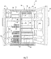
- FIG. 1 provides a front view of a representative refrigerator appliance 10 according to an example embodiment of the present disclosure. More specifically, for illustrative purposes, the present disclosure is described in the context of a refrigerator appliance 10 having a construction as shown and described further below.
- a refrigerator appliance includes appliances such as a refrigerator/freezer combination, side-by-side, bottom mount, compact, and any other style or model of refrigerator appliance. Accordingly, other configurations including multiple and different styled compartments may be used with refrigerator appliance 10, it being understood that the configuration shown in FIG. 1 is provided by way of example only.
- Refrigerator appliance 10 includes a fresh food storage compartment 12 and a freezer storage compartment 14.
- freezer compartment 14 and fresh food compartment 12 are arranged side-by-side within an outer case 16 and defined by inner liners 18 and 20 therein.
- a space between case 16 and liners 18, 20 and between liners 18, 20 may be filled with foamed-in-place insulation.
- Outer case 16 normally is formed by folding a sheet of a suitable material, such as pre-painted steel, into an inverted U-shape to form the top and side walls of case 16.
- a bottom wall of case 16 normally is formed separately and attached to the case side walls and to a bottom frame that provides support for refrigerator appliance 10.
- Inner liners 18 and 20 are molded from a suitable plastic material to form freezer compartment 14 and fresh food compartment 12, respectively.
- liners 18, 20 may be formed by bending and welding a sheet of a suitable metal, such as steel.
- Outer case 16 and liners 18, 20 may collectively form a housing or casing of refrigerator appliance 10.
- a breaker strip 22 extends between a case front flange and outer front edges of liners 18, 20.
- Breaker strip 22 is formed from a suitable resilient material, such as an extruded acrylo-butadiene-styrene based material (commonly referred to as ABS).
- ABS extruded acrylo-butadiene-styrene based material
- mullion 24 is formed of an extruded ABS material.
- Breaker strip 22 and mullion 24 form a front face, and extend completely around inner peripheral edges of case 16 and vertically between liners 18, 20.
- refrigerator appliance 10 includes shelves 28 and slide-out storage drawers 30, sometimes referred to as storage pans, which normally are provided in fresh food compartment 12 to support items being stored therein.
- Refrigerator appliance 10 can be operated by one or more controllers 11 or other processing devices according to programming or user preference via manipulation of a control interface 32 mounted (e.g., in an upper region of fresh food storage compartment 12 and connected with controller 11).
- Controller 11 may include one or more memory devices (e.g., non-transitive memory) and one or more microprocessors, such as a general or special purpose microprocessor operable to execute programming instructions or micro-control code associated with the operation of the refrigerator appliance 10.
- the memory may represent random access memory such as DRAM, or read only memory such as ROM or FLASH.
- the processor executes programming instructions stored in memory.
- the memory may be a separate component from the processor or may be included onboard within the processor.
- Controller 11 may include one or more proportional-integral (“PI") controllers programmed, equipped, or configured to operate the refrigerator appliance according to various control methods. Accordingly, as used herein, "controller” includes the singular and plural forms.
- PI proportional-integral
- Controller 11 may be positioned in a variety of locations throughout refrigerator appliance 10. In the illustrated embodiment, controller 11 may be located, for example, behind an interface panel 32 or doors 42 or 44. Input/output ("I/O") signals may be routed between the control system and various operational components of refrigerator appliance 10 along wiring harnesses that may be routed through, for example, the back, sides, or mullion 26. Typically, through user interface panel 32, a user may select various operational features and modes and monitor the operation of refrigerator appliance 10. In one embodiment, the user interface panel 32 may represent a general purpose I/O ("GPIO”) device or functional block.
- GPIO general purpose I/O
- the user interface panel 32 may include input components, such as one or more of a variety of electrical, mechanical or electro-mechanical input devices including rotary dials, push buttons, and touch pads.
- the user interface panel 32 may include a display component, such as a digital or analog display device designed to provide operational feedback to a user.
- User interface panel 32 may be in communication with controller 11 via one or more signal lines or shared communication busses.
- one or more temperature sensors are provided to measure the temperature in the fresh food compartment 12 and the temperature in the freezer compartment 14.
- first temperature sensor 52 may be disposed in the fresh food compartment 12 and may measure the temperature in the fresh food compartment 12.
- Second temperature sensor 54 may be disposed in the freezer compartment 14 and may measure the temperature in the freezer compartment 14. This temperature information can be provided (e.g., to controller 11 for use in operating refrigerator 10). These temperature measurements may be taken intermittently or continuously during operation of the appliance or execution of a control system.
- a shelf 34 and wire baskets 36 may be provided in freezer compartment 14. Additionally or alternatively, an ice maker 38 may be provided in freezer compartment 14.
- a freezer door 42 and a fresh food door 44 close access openings to freezer and fresh food compartments 14, 12, respectively. Each door 42, 44 is mounted to rotate about its outer vertical edge between an open position, as shown in FIG. 1 , and a closed position (not shown) closing the associated storage compartment. In alternative embodiments, one or both doors 42, 44 may be slidable or otherwise movable between open and closed positions. Freezer door 42 includes a plurality of storage shelves 46, and fresh food door 44 includes a plurality of storage shelves 48.
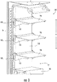
- FIGS. 2 and 3 are partial perspective views of a shelf assembly 100 of refrigerator appliance 10. While described in greater detail below in the context of refrigerator appliance 10, it will be understood that shelf assembly 100 may be used in any suitable appliance in alternative example embodiments. For example, shelf assembly 100 may be used in a top-mount refrigerator appliance, a bottom-mount refrigerator appliance, a stand-alone freezer appliance, etc. As discussed in greater detail below, shelf assembly 100 includes features for motorized movement of shelves 110, such as shelves 28. In particular, shelf assembly 100 may be operable to selectively move one or more of shelves 110 with a single motor.
- shelf assembly 100 is shown with a cover 102.
- Cover 102 may face fresh food storage compartment 12, e.g., and may form a portion of liner 18.
- Cover 102 may overlay various internal components of shelf assembly 100, as shown in FIG. 2 in which cover 102 is removed.
- the motorized components of shelf assembly 100 may be hidden behind cover 102 to improve a cosmetic appearance of shelf assembly 100.
- shelf assembly 100 includes a plurality of shelves 110. Shelves 110 are moveable along a vertical direction V within fresh food storage compartment 12.
- shelf assembly 100 also includes a lead screw 120.
- Lead screw 120 is mounted within fresh food storage compartment 12 such that lead screw 120 is rotatable.
- shelf assembly 100 may include a motor 130 (shown schematically in FIG. 2 ) coupled to lead screw 120, and motor 130 may be operable to rotate lead screw 120.
- Motor 130 may be positioned at a top or bottom of lead screw 120. By rotating lead screw 120, motor 130 may move one or more of shelves 110, e.g., along the vertical direction V, within fresh food storage compartment 12.
- Each shelf 110 may include a shelf support or bracket 112. Shelf support 112 may be mounted on a track 114, e.g., that restrains movement of shelf support 112 to along the vertical direction V. Thus, shelf support 112 may translate along the vertical direction V in fresh food storage compartment 12 (or freezer compartment 14 in alternative example embodiments). Each shelf 110 may also include a panel 116 positioned on shelf support 112. Panel 116 may be removable from shelf support 112, e.g., to facilitate cleaning of panel 116. Various food items may be stored on panels 116. In FIG. 2 , each shelf 110 includes two shelf supports 112. In alternative example embodiments, each shelf 110 may include one, three, or more shelf supports 112.
- Shelf assembly 100 also includes a plurality of clutches 140.
- Each clutch 140 may mounted to a respective shelf support 112.
- Each clutch 140 may also be selectively opened and closed to connect the respective shelf support 112 to lead screw 120.
- the clutch 140 is closed, the respective shelf support 112 is coupled to lead screw 120 such that rotation of lead screw 120 by motor 130 moves the respective shelf support 112 along the vertical direction V.
- the clutch 140 is opened, the respective shelf support 112 is disconnected from lead screw 120 such that rotation of lead screw 120 by motor 130 does not move the respective shelf support 112 along the vertical direction V.
- clutches 140 may regulate vertical movement of shelves 110.
- shelf assembly 100 includes three shelves 110. It will be understood that this is provided by way of example only. In alternative example embodiments, shelf assembly 100 may include one, two, four, or more shelves 110. One, two, or all three of clutches 140 in FIG. 2 may be closed to move the respective shelf support 112 along the vertical direction V by rotating lead screw 120 with motor 130. Conversely, one, two, or all three of clutches 140 in FIG. 2 may be opened to keep the respective shelf support 112 at a fixed position along the vertical direction V despite rotation of lead screw 120 with motor 130. As may be seen from the above, one, two, or all three of shelves 110 may be vertically moved with motor 130 by selectively closing the respective clutch 140. Thus, only one motor 130 may be used to move only one shelf 110 or to move two/three of shelves 110 simultaneously.
- FIG. 4 is a perspective view of clutch 140 and lead screw 120.
- FIG. 5 is an elevation view of clutch 140.
- FIG. 6 is a partial elevation view of clutch 140.
- shelf support 112 includes a housing 118. Housing 118 may be fixed relative to panel 116 when panel 116 is positioned on shelf support 112. Housing 118 contains various components of clutch 140, as discussed in greater detail below.
- clutch 140 includes a nut 150, a bearing assembly 160, a locking plunger 170 and an actuator 180.
- Nut 150 is disposed within housing 118 and is threaded on lead screw 120. Thus, e.g., an inner threaded surface of nut 150 may be engaged with an outer threaded surface of lead screw 120.
- Nut 150 has a plurality of teeth 152 at an outer surface 154 of nut 150. Teeth 152 may be circumferentially distributed on outer surface 154 of nut 150 and/or may extend axially along outer surface 154 of nut 150.
- Bearing assembly 160 is positioned between a top 156 of nut 150 and housing 118.
- bearing assembly 160 may be positioned within housing 118 and may extend between nut 150 and housing 118.
- lead screw 120 may extend through bearing assembly 160, e.g., within housing 118.
- Bearing assembly 160 assists with allowing nut 150 to rotate within housing 118.
- bearing assembly 160 may include a first washer 162, a second washer 164 and a plurality of bearings 166.
- First washer 162 is positioned on or against housing 118
- second washer 164 is positioned on or against nut 150.
- Bearings 166 are positioned between and ride on first and second washers 162, 164.
- bearings 166 may roll on first and second washers 162, 164 to facilitate rotation of nut 150 relative to housing 118.
- Bearings 166 may be roller bearings in certain example embodiments, and may be connected to on another with a race. Bearings 166 may also be circumferentially distributed about lead screw 120 between first and second washers 162, 164.
- Locking plunger 170 has at least one tooth 172, e.g., that is commentary to teeth 152 of nut 150, and actuator 180 is coupled to locking plunger 170.
- Actuator 180 is operable to selectively mesh the at least one tooth 172 of locking plunger 170 with teeth 152 of nut 150.
- locking plunger 170 may be pivotally mounted to housing 118, and actuator 180 may pivot locking plunger 170 on housing 118 to selectively mesh the at least one tooth 172 of locking plunger 170 with teeth 152 of nut 150.
- Locking plunger 170 may have a first end portion 174 and a second end portion 174, and locking plunger 170 may be pivotally mounted to housing 118 between first and second end portions 174, 176 of locking plunger 170.
- the at least one tooth 172 of locking plunger 170 may be positioned at first end portion 174 of locking plunger 170, and locking plunger 170 may be coupled to actuator 180 at second end portion 176 of locking plunger 170.
- Locking plunger 170 may be L-shaped between first and second end portions 174, 176 of locking plunger 170.
- Actuator 180 may be a solenoid, such as a direct current pull solenoid.
- actuator 180 may have a plunger 182 and a casing 184.
- One of plunger and casing 182, 184 of solenoid 180 may be positioned at and connected to second end portion 176 of locking plunger 170, and the other of plunger and casing 182, 184 of solenoid 180 may be positioned at and connected to housing 118.
- actuator 180 may be a shape-memory alloy, a linear actuator, etc.
- nut 150 By meshing the at least one tooth 172 of locking plunger 170 with teeth 152 of nut 150, rotation of nut 150 relative to lead screw 120 may be regulated.
- nut 150 may be fixed relative to lead screw 120 when actuator 180 does not mesh the at least one tooth 172 of locking plunger 170 with teeth 152 of nut 150.
- actuator 180 may rotate with lead screw 120 such that the position of shelf support 112 along the vertical direction V does not change (or insubstantially changes) despite rotation of lead screw 120 with motor 130.
- nut 150 is rotatable relative to lead screw 120 when actuator 180 meshes the at least one tooth 172 of locking plunger 170 with teeth 152 of nut 150.
- nut 150 may rotate relative to lead screw 120 such that the position of shelf support 112 along the vertical direction V changes due to the rotation of lead screw 120.
- clutches 140 may regulate vertical movement of shelves 110.
- shelf assembly 100 may advantageously provide fully adjustable, automatic height control for shelves 110 within refrigerator appliance 10.
- Shelf assembly 100 utilizes clutches 140 to engage a respective shelf 110 to lead screw 120.
- actuator 180 may mesh the at least one tooth 172 of locking plunger 170 with teeth 152 of nut 150 in order to prevent rotation of nut 150.
- Nut 150 is thus driven up or down on lead screw 120, which forces the engaged shelf 110 up or down, depending on the rotational direction of lead screw 120. All shelves 110 whose nuts 150 are not engaged during rotation of lead screw 120 are kept vertically in place.
- Clutches 140 may also include additional features for discouraging rotation of nut 150 on lead screw 120 when actuator 180 does not mesh the at least one tooth 172 of locking plunger 170 with teeth 152 of nut 150.
- nut 150 may include a direct interfering thread 158 on at least a portion of the thread coupling between nut 150 and lead screw 120. Direct interfering thread 158 forms a slight interference fit between nut 150 and lead screw 120, e.g., due to an oversized root diameter of lead screw 120 relative to nut 150, that discourages rotation of nut 150 on lead screw 120 when actuator 180 does not mesh the at least one tooth 172 of locking plunger 170 with teeth 152 of nut 150.
- nut 150 may include a nylon seal 159, such as a Nyloc-inspired ring, that contacts lead screw 120.
- nut 150 may include drag-inducing such as additional plastic threads, Nyloc-inspired rings, etc. to further bias a disengaged nut 150 to rotate with lead screw 120.
Landscapes
- Engineering & Computer Science (AREA)
- Chemical & Material Sciences (AREA)
- Combustion & Propulsion (AREA)
- Physics & Mathematics (AREA)
- Mechanical Engineering (AREA)
- Thermal Sciences (AREA)
- General Engineering & Computer Science (AREA)
- Refrigerator Housings (AREA)
- Transmission Devices (AREA)
Abstract
Description
- The present subject matter relates generally to appliances with adjustable shelves.
- Refrigerator appliances generally include a cabinet that defines a chilled chamber for receipt of food articles for storage. Refrigerator appliances can also include various internal storage components mounted within the chilled chamber and designed to facilitate storage of food items therein. Such storage components include racks, bins, shelves, and/or drawers that receive food items and assist with organizing and arranging of such food items within the chilled chamber. Certain conventional refrigerator appliances include adjustable shelves that can be moved from one shelf mounting position to another within the refrigerator appliance. In this manner, the configuration of shelves within the refrigerator can be selected to suit the user's needs.
- Known refrigerator appliances include slotted tracks mounted on a rear wall of the appliance. Shelves with mounting supports engage slots in the slotted tracks such that a user may manually remove and reposition the shelf. However, movement of such shelves is labor intensive and time consuming. In particular, the user must remove all items on the shelf, pop the shelf out of the slotted track, and reposition the shelf before returning the removed items.
- Aspects and advantages of the invention will be set forth in part in the following description, or may be apparent from the description, or may be learned through practice of the invention.
- In an example embodiment, an appliance includes a cabinet and a shelf assembly. The shelf assembly includes a lead screw mounted to the cabinet such that the lead screw is rotatable. A shelf support is mounted to the cabinet such the shelf support is translatable relative to the lead screw. The shelf support has a housing. A nut is disposed within the housing of the shelf support and is threaded on the lead screw. The nut has a plurality of teeth at an outer surface of the nut. A locking plunger has at least one tooth. An actuator is coupled to the locking plunger. The actuator is operable to selectively mesh the at least one tooth of the locking plunger with the plurality of teeth of the nut.
- In another example embodiment, an appliance includes a cabinet and a shelf assembly. The shelf assembly includes a lead screw mounted to the cabinet such that the lead screw is rotatable. A first shelf support is mounted to the cabinet such the first shelf support is translatable relative to the lead screw. The first shelf support has a first housing. A first nut is disposed within the first housing and is threaded on the lead screw. The first nut has a plurality of teeth at an outer surface of the first nut. A first locking plunger has at least one tooth. A first actuator is coupled to the first locking plunger. The first actuator is operable to selectively mesh the at least one tooth of the first locking plunger with the plurality of teeth of the first nut. A second shelf support is mounted to the cabinet such the second shelf support is translatable relative to the lead screw. The second shelf support has a second housing. The second shelf support is separate from the first shelf support on the cabinet. A second nut is disposed within the second housing and is threaded on the lead screw. The second nut has a plurality of teeth at an outer surface of the second nut. A second locking plunger has at least one tooth. A second actuator is coupled to the second locking plunger. The second actuator is operable to selectively mesh the at least one tooth of the second locking plunger with the plurality of teeth of the second nut.
- These and other features, aspects and advantages of the present invention will become better understood with reference to the following description and appended claims. The accompanying drawings, which are incorporated in and constitute a part of this specification, illustrate embodiments of the invention and, together with the description, serve to explain the principles of the invention.
- A full and enabling disclosure of the present invention, including the best mode thereof, directed to one of ordinary skill in the art, is set forth in the specification, which makes reference to the appended figures.
-
FIG. 1 is a front perspective view of a refrigerator appliance according to an example embodiment. -
FIGS. 2 and3 are partial perspective views of a shelf assembly of the example refrigerator appliance ofFIG. 1 . -
FIG. 4 is a perspective view of a clutch and lead screw of the shelf assembly ofFIG. 3 . -
FIG. 5 is an elevation view of the clutch ofFIG. 4 positioned within a housing of the shelf assembly. -
FIG. 6 is a partial elevation view of the clutch ofFIG. 5 . -
FIG. 7 is an elevation view of a nut of the clutch ofFIG. 5 with a direct interfering thread. -
FIG. 8 is an elevation view of a nut according to another example embodiment with a nylon seal. - Reference now will be made in detail to embodiments of the invention, one or more examples of which are illustrated in the drawings. Each example is provided by way of explanation of the invention, not limitation of the invention. In fact, it will be apparent to those skilled in the art that various modifications and variations can be made in the present invention without departing from the scope or spirit of the invention. For instance, features illustrated or described as part of one embodiment can be used with another embodiment to yield a still further embodiment. Thus, it is intended that the present invention covers such modifications and variations as come within the scope of the appended claims and their equivalents.
-
FIG. 1 provides a front view of arepresentative refrigerator appliance 10 according to an example embodiment of the present disclosure. More specifically, for illustrative purposes, the present disclosure is described in the context of arefrigerator appliance 10 having a construction as shown and described further below. As used herein, a refrigerator appliance includes appliances such as a refrigerator/freezer combination, side-by-side, bottom mount, compact, and any other style or model of refrigerator appliance. Accordingly, other configurations including multiple and different styled compartments may be used withrefrigerator appliance 10, it being understood that the configuration shown inFIG. 1 is provided by way of example only. -
Refrigerator appliance 10 includes a freshfood storage compartment 12 and afreezer storage compartment 14. In this embodiment,freezer compartment 14 andfresh food compartment 12 are arranged side-by-side within anouter case 16 and defined byinner liners case 16 andliners liners Outer case 16 normally is formed by folding a sheet of a suitable material, such as pre-painted steel, into an inverted U-shape to form the top and side walls ofcase 16. A bottom wall ofcase 16 normally is formed separately and attached to the case side walls and to a bottom frame that provides support forrefrigerator appliance 10.Inner liners freezer compartment 14 andfresh food compartment 12, respectively. Alternatively,liners Outer case 16 andliners refrigerator appliance 10. - A
breaker strip 22 extends between a case front flange and outer front edges ofliners Breaker strip 22 is formed from a suitable resilient material, such as an extruded acrylo-butadiene-styrene based material (commonly referred to as ABS). The insulation in the space betweenliners mullion 24. In one embodiment,mullion 24 is formed of an extruded ABS material.Breaker strip 22 andmullion 24 form a front face, and extend completely around inner peripheral edges ofcase 16 and vertically betweenliners Mullion 24, insulation between compartments, and a spaced wall of liners separating compartments, sometimes are collectively referred to herein as acenter mullion wall 26. In addition,refrigerator appliance 10 includesshelves 28 and slide-outstorage drawers 30, sometimes referred to as storage pans, which normally are provided infresh food compartment 12 to support items being stored therein. -
Refrigerator appliance 10 can be operated by one ormore controllers 11 or other processing devices according to programming or user preference via manipulation of acontrol interface 32 mounted (e.g., in an upper region of freshfood storage compartment 12 and connected with controller 11).Controller 11 may include one or more memory devices (e.g., non-transitive memory) and one or more microprocessors, such as a general or special purpose microprocessor operable to execute programming instructions or micro-control code associated with the operation of therefrigerator appliance 10. The memory may represent random access memory such as DRAM, or read only memory such as ROM or FLASH. In one embodiment, the processor executes programming instructions stored in memory. The memory may be a separate component from the processor or may be included onboard within the processor.Controller 11 may include one or more proportional-integral ("PI") controllers programmed, equipped, or configured to operate the refrigerator appliance according to various control methods. Accordingly, as used herein, "controller" includes the singular and plural forms. -
Controller 11 may be positioned in a variety of locations throughoutrefrigerator appliance 10. In the illustrated embodiment,controller 11 may be located, for example, behind aninterface panel 32 ordoors refrigerator appliance 10 along wiring harnesses that may be routed through, for example, the back, sides, ormullion 26. Typically, throughuser interface panel 32, a user may select various operational features and modes and monitor the operation ofrefrigerator appliance 10. In one embodiment, theuser interface panel 32 may represent a general purpose I/O ("GPIO") device or functional block. In one embodiment, theuser interface panel 32 may include input components, such as one or more of a variety of electrical, mechanical or electro-mechanical input devices including rotary dials, push buttons, and touch pads. Theuser interface panel 32 may include a display component, such as a digital or analog display device designed to provide operational feedback to a user.User interface panel 32 may be in communication withcontroller 11 via one or more signal lines or shared communication busses. - In some embodiments, one or more temperature sensors are provided to measure the temperature in the
fresh food compartment 12 and the temperature in thefreezer compartment 14. For example,first temperature sensor 52 may be disposed in thefresh food compartment 12 and may measure the temperature in thefresh food compartment 12.Second temperature sensor 54 may be disposed in thefreezer compartment 14 and may measure the temperature in thefreezer compartment 14. This temperature information can be provided (e.g., tocontroller 11 for use in operating refrigerator 10). These temperature measurements may be taken intermittently or continuously during operation of the appliance or execution of a control system. - Optionally, a
shelf 34 andwire baskets 36 may be provided infreezer compartment 14. Additionally or alternatively, anice maker 38 may be provided infreezer compartment 14. Afreezer door 42 and afresh food door 44 close access openings to freezer andfresh food compartments door FIG. 1 , and a closed position (not shown) closing the associated storage compartment. In alternative embodiments, one or bothdoors Freezer door 42 includes a plurality ofstorage shelves 46, andfresh food door 44 includes a plurality ofstorage shelves 48. -
FIGS. 2 and3 are partial perspective views of ashelf assembly 100 ofrefrigerator appliance 10. While described in greater detail below in the context ofrefrigerator appliance 10, it will be understood thatshelf assembly 100 may be used in any suitable appliance in alternative example embodiments. For example,shelf assembly 100 may be used in a top-mount refrigerator appliance, a bottom-mount refrigerator appliance, a stand-alone freezer appliance, etc. As discussed in greater detail below,shelf assembly 100 includes features for motorized movement ofshelves 110, such asshelves 28. In particular,shelf assembly 100 may be operable to selectively move one or more ofshelves 110 with a single motor. - In
FIG. 3 ,shelf assembly 100 is shown with acover 102. Cover 102 may face freshfood storage compartment 12, e.g., and may form a portion ofliner 18. Cover 102 may overlay various internal components ofshelf assembly 100, as shown inFIG. 2 in which cover 102 is removed. Thus, e.g., the motorized components ofshelf assembly 100 may be hidden behindcover 102 to improve a cosmetic appearance ofshelf assembly 100. With reference toFIG. 3 ,shelf assembly 100 includes a plurality ofshelves 110.Shelves 110 are moveable along a vertical direction V within freshfood storage compartment 12. - Turning to
FIG. 2 ,shelf assembly 100 also includes alead screw 120.Lead screw 120 is mounted within freshfood storage compartment 12 such thatlead screw 120 is rotatable. For example,shelf assembly 100 may include a motor 130 (shown schematically inFIG. 2 ) coupled to leadscrew 120, andmotor 130 may be operable to rotatelead screw 120.Motor 130 may be positioned at a top or bottom oflead screw 120. By rotatinglead screw 120,motor 130 may move one or more ofshelves 110, e.g., along the vertical direction V, within freshfood storage compartment 12. - Each
shelf 110 may include a shelf support orbracket 112.Shelf support 112 may be mounted on atrack 114, e.g., that restrains movement ofshelf support 112 to along the vertical direction V. Thus,shelf support 112 may translate along the vertical direction V in fresh food storage compartment 12 (orfreezer compartment 14 in alternative example embodiments). Eachshelf 110 may also include apanel 116 positioned onshelf support 112.Panel 116 may be removable fromshelf support 112, e.g., to facilitate cleaning ofpanel 116. Various food items may be stored onpanels 116. InFIG. 2 , eachshelf 110 includes two shelf supports 112. In alternative example embodiments, eachshelf 110 may include one, three, or more shelf supports 112. -
Shelf assembly 100 also includes a plurality ofclutches 140. Each clutch 140 may mounted to arespective shelf support 112. Each clutch 140 may also be selectively opened and closed to connect therespective shelf support 112 to leadscrew 120. When the clutch 140 is closed, therespective shelf support 112 is coupled to leadscrew 120 such that rotation oflead screw 120 bymotor 130 moves therespective shelf support 112 along the vertical direction V. Conversely, when the clutch 140 is opened, therespective shelf support 112 is disconnected fromlead screw 120 such that rotation oflead screw 120 bymotor 130 does not move therespective shelf support 112 along the vertical direction V. Thus,clutches 140 may regulate vertical movement ofshelves 110. - In
FIG. 2 ,shelf assembly 100 includes threeshelves 110. It will be understood that this is provided by way of example only. In alternative example embodiments,shelf assembly 100 may include one, two, four, ormore shelves 110. One, two, or all three ofclutches 140 inFIG. 2 may be closed to move therespective shelf support 112 along the vertical direction V by rotatinglead screw 120 withmotor 130. Conversely, one, two, or all three ofclutches 140 inFIG. 2 may be opened to keep therespective shelf support 112 at a fixed position along the vertical direction V despite rotation oflead screw 120 withmotor 130. As may be seen from the above, one, two, or all three ofshelves 110 may be vertically moved withmotor 130 by selectively closing therespective clutch 140. Thus, only onemotor 130 may be used to move only oneshelf 110 or to move two/three ofshelves 110 simultaneously. -
FIG. 4 is a perspective view ofclutch 140 andlead screw 120.FIG. 5 is an elevation view ofclutch 140.FIG. 6 is a partial elevation view ofclutch 140. With reference toFIGS. 2 and5 ,shelf support 112 includes ahousing 118.Housing 118 may be fixed relative topanel 116 whenpanel 116 is positioned onshelf support 112.Housing 118 contains various components ofclutch 140, as discussed in greater detail below. - With reference to
FIGS. 4 through 6 , clutch 140 includes anut 150, a bearingassembly 160, a lockingplunger 170 and anactuator 180.Nut 150 is disposed withinhousing 118 and is threaded onlead screw 120. Thus, e.g., an inner threaded surface ofnut 150 may be engaged with an outer threaded surface oflead screw 120.Nut 150 has a plurality ofteeth 152 at anouter surface 154 ofnut 150.Teeth 152 may be circumferentially distributed onouter surface 154 ofnut 150 and/or may extend axially alongouter surface 154 ofnut 150. -
Bearing assembly 160 is positioned between a top 156 ofnut 150 andhousing 118. Thus, e.g., bearingassembly 160 may be positioned withinhousing 118 and may extend betweennut 150 andhousing 118. In addition,lead screw 120 may extend through bearingassembly 160, e.g., withinhousing 118.Bearing assembly 160 assists with allowingnut 150 to rotate withinhousing 118. For example, bearingassembly 160 may include afirst washer 162, asecond washer 164 and a plurality ofbearings 166.First washer 162 is positioned on or againsthousing 118, andsecond washer 164 is positioned on or againstnut 150.Bearings 166 are positioned between and ride on first andsecond washers bearings 166 may roll on first andsecond washers nut 150 relative tohousing 118.Bearings 166 may be roller bearings in certain example embodiments, and may be connected to on another with a race.Bearings 166 may also be circumferentially distributed aboutlead screw 120 between first andsecond washers - Locking
plunger 170 has at least onetooth 172, e.g., that is commentary toteeth 152 ofnut 150, andactuator 180 is coupled to lockingplunger 170.Actuator 180 is operable to selectively mesh the at least onetooth 172 of lockingplunger 170 withteeth 152 ofnut 150. For example, lockingplunger 170 may be pivotally mounted tohousing 118, andactuator 180 may pivot lockingplunger 170 onhousing 118 to selectively mesh the at least onetooth 172 of lockingplunger 170 withteeth 152 ofnut 150. - Locking
plunger 170 may have afirst end portion 174 and asecond end portion 174, and lockingplunger 170 may be pivotally mounted tohousing 118 between first andsecond end portions plunger 170. The at least onetooth 172 of lockingplunger 170 may be positioned atfirst end portion 174 of lockingplunger 170, and lockingplunger 170 may be coupled toactuator 180 atsecond end portion 176 of lockingplunger 170. Lockingplunger 170 may be L-shaped between first andsecond end portions plunger 170. -
Actuator 180 may be a solenoid, such as a direct current pull solenoid. Thus, e.g.,actuator 180 may have aplunger 182 and acasing 184. One of plunger andcasing solenoid 180 may be positioned at and connected tosecond end portion 176 of lockingplunger 170, and the other of plunger andcasing solenoid 180 may be positioned at and connected tohousing 118. In alternative example embodiments,actuator 180 may be a shape-memory alloy, a linear actuator, etc. - By meshing the at least one
tooth 172 of lockingplunger 170 withteeth 152 ofnut 150, rotation ofnut 150 relative to leadscrew 120 may be regulated. For example,nut 150 may be fixed relative to leadscrew 120 whenactuator 180 does not mesh the at least onetooth 172 of lockingplunger 170 withteeth 152 ofnut 150. Thus, e.g., whenmotor 130 rotateslead screw 120,nut 150 may rotate withlead screw 120 such that the position ofshelf support 112 along the vertical direction V does not change (or insubstantially changes) despite rotation oflead screw 120 withmotor 130. In contrast,nut 150 is rotatable relative to leadscrew 120 whenactuator 180 meshes the at least onetooth 172 of lockingplunger 170 withteeth 152 ofnut 150. Thus, e.g., whenmotor 130 rotateslead screw 120,nut 150 may rotate relative to leadscrew 120 such that the position ofshelf support 112 along the vertical direction V changes due to the rotation oflead screw 120. In such a manner,clutches 140 may regulate vertical movement ofshelves 110. - As may be seen from the above,
shelf assembly 100 may advantageously provide fully adjustable, automatic height control forshelves 110 withinrefrigerator appliance 10.Shelf assembly 100 utilizesclutches 140 to engage arespective shelf 110 to leadscrew 120. For eachshelf 110,actuator 180 may mesh the at least onetooth 172 of lockingplunger 170 withteeth 152 ofnut 150 in order to prevent rotation ofnut 150.Nut 150 is thus driven up or down onlead screw 120, which forces the engagedshelf 110 up or down, depending on the rotational direction oflead screw 120. Allshelves 110 whosenuts 150 are not engaged during rotation oflead screw 120 are kept vertically in place. No vertical movement ofsuch shelves 110 occurs because the weight of theshelf 110 rests on bearingassembly 160 which transfers the weight tonut 150, thus allowingnut 150 to rotate in correspondence withlead screw 120 due to the greater friction within the thread coupling betweennut 150 andlead screw 120 than that within bearingassembly 160. -
Clutches 140 may also include additional features for discouraging rotation ofnut 150 onlead screw 120 whenactuator 180 does not mesh the at least onetooth 172 of lockingplunger 170 withteeth 152 ofnut 150. As shown inFIG. 7 ,nut 150 may include a direct interferingthread 158 on at least a portion of the thread coupling betweennut 150 andlead screw 120. Direct interferingthread 158 forms a slight interference fit betweennut 150 andlead screw 120, e.g., due to an oversized root diameter oflead screw 120 relative tonut 150, that discourages rotation ofnut 150 onlead screw 120 whenactuator 180 does not mesh the at least onetooth 172 of lockingplunger 170 withteeth 152 ofnut 150. As another example,nut 150 may include anylon seal 159, such as a Nyloc-inspired ring, that contacts leadscrew 120. As may be seen from the above,nut 150 may include drag-inducing such as additional plastic threads, Nyloc-inspired rings, etc. to further bias adisengaged nut 150 to rotate withlead screw 120. - This written description uses examples to disclose the invention, including the best mode, and also to enable any person skilled in the art to practice the invention, including making and using any devices or systems and performing any incorporated methods. The patentable scope of the invention is defined by the claims, and may include other examples that occur to those skilled in the art. Such other examples are intended to be within the scope of the claims if they include structural elements that do not differ from the literal language of the claims, or if they include equivalent structural elements with insubstantial differences from the literal languages of the claims.
Claims (20)
- An appliance, comprising:a cabinet; anda shelf assembly comprisinga lead screw mounted to the cabinet such that the lead screw is rotatable,a shelf support mounted to the cabinet such the shelf support is translatable relative to the lead screw, the shelf support having a housing,a nut disposed within the housing of the shelf support and threaded on the lead screw, the nut having a plurality of teeth at an outer surface of the nut,a locking plunger having at least one tooth, andan actuator coupled to the locking plunger, the actuator operable to selectively mesh the at least one tooth of the locking plunger with the plurality of teeth of the nut.
- The appliance of claim 1, wherein the shelf assembly further comprises a motor coupled to the lead screw, and the motor is operable to rotate the lead screw.
- The appliance of claim 2, wherein the nut is fixed relative to the lead screw when the motor operates to rotate the lead screw and the actuator does not mesh the at least one tooth of the locking plunger with the plurality of teeth of the nut, and the nut rotates relative to the lead screw when the motor operates to rotate the lead screw and the actuator meshes the at least one tooth of the locking plunger with the plurality of teeth of the nut.
- The appliance of claim 1, wherein the actuator is a solenoid.
- The appliance of claim 1, further comprising a bearing assembly positioned between a top of the nut and the housing of the shelf support, wherein the lead screw extends through the bearing assembly.
- The appliance of claim 5, wherein the bearing assembly comprises:a first washer positioned on the housing;a second washer positioned on the nut; anda plurality of bearings positioned between and riding on the first and second washers.
- The appliance of claim 6, wherein the plurality of bearings is a plurality of roller bearings.
- The appliance of claim 1, wherein the locking plunger is pivotally mounted to the housing.
- The appliance of claim 8, wherein the locking plunger had a first end portion and a second end portion, the locking plunger is pivotally mounted to the housing between the first and second end portions of the locking plunger, the at least one tooth of the locking plunger is positioned at the first end portion of the locking plunger, and the locking plunger is coupled to the actuator at the second end portion of the locking plunger.
- The appliance of claim 9, wherein the actuator is a solenoid having a plunger and a casing, one of the plunger and the casing of the solenoid is positioned at and connected to the second end portion of the locking plunger, and the other of the plunger and the casing of the solenoid is positioned at and connected to the housing.
- The appliance of claim 1, wherein the nut defines an internal threaded surface, at least a portion of the internal threaded surface of the nut forming a direct interfering thread with the lead screw.
- The appliance of claim 1, wherein the nut comprises at least one nylon seal that contacts the lead screw.
- The appliance of claim 1, wherein the shelf assembly further comprises a panel mounted on the shelf support.
- An appliance, comprising:a cabinet; anda shelf assembly comprisinga lead screw mounted to the cabinet such that the lead screw is rotatable,a first shelf support mounted to the cabinet such the first shelf support is translatable relative to the lead screw, the first shelf support having a first housing,a first nut disposed within the first housing and threaded on the lead screw, the first nut having a plurality of teeth at an outer surface of the first nut,a first locking plunger having at least one tooth,a first actuator coupled to the first locking plunger, the first actuator operable to selectively mesh the at least one tooth of the first locking plunger with the plurality of teeth of the first nut,a second shelf support mounted to the cabinet such the second shelf support is translatable relative to the lead screw, the second shelf support having a second housing, the second shelf support separate from the first shelf support on the cabinet,a second nut disposed within the second housing and threaded on the lead screw, the second nut having a plurality of teeth at an outer surface of the second nut,a second locking plunger having at least one tooth, anda second actuator coupled to the second locking plunger, the second actuator operable to selectively mesh the at least one tooth of the second locking plunger with the plurality of teeth of the second nut.
- The appliance of claim 14, wherein the shelf assembly further comprises a motor coupled to the lead screw, and the motor is operable to rotate the lead screw.
- The appliance of claim 15, wherein the first nut is fixed relative to the lead screw when the motor operates to rotate the lead screw and the first actuator does not mesh the at least one tooth of the first locking plunger with the plurality of teeth of the first nut, and the first nut rotates relative to the lead screw when the motor operates to rotate the lead screw and the first actuator meshes the at least one tooth of the first locking plunger with the plurality of teeth of the first nut.
- The appliance of claim 14, further comprising:a first bearing assembly positioned between a top of the first nut and the first housing; anda second bearing assembly positioned between a top of the second nut and the second housing,wherein the lead screw extends through the first and second bearing assemblies.
- The appliance of claim 17, wherein the first bearing assembly comprises:a first washer positioned on the first housing;a second washer positioned on the first nut; anda plurality of bearings positioned between and riding on the first and second washers.
- The appliance of claim 14, wherein the first nut defines an internal threaded surface, at least a portion of the internal threaded surface of the first nut forming a direct interfering thread with the lead screw.
- The appliance of claim 14, wherein the first nut comprises at least one nylon seal that contacts the lead screw.
Applications Claiming Priority (2)
| Application Number | Priority Date | Filing Date | Title |
|---|---|---|---|
| US16/578,680 US11125491B2 (en) | 2019-09-23 | 2019-09-23 | Adjustable shelf assembly for an appliance |
| PCT/CN2020/117034 WO2021057767A1 (en) | 2019-09-23 | 2020-09-23 | Refrigeration appliance with adjustable rack assembly |
Publications (3)
| Publication Number | Publication Date |
|---|---|
| EP4036502A1 true EP4036502A1 (en) | 2022-08-03 |
| EP4036502A4 EP4036502A4 (en) | 2022-11-02 |
| EP4036502B1 EP4036502B1 (en) | 2025-03-05 |
Family
ID=74880702
Family Applications (1)
| Application Number | Title | Priority Date | Filing Date |
|---|---|---|---|
| EP20867363.2A Active EP4036502B1 (en) | 2019-09-23 | 2020-09-23 | Refrigeration appliance with an adjustable shelf assembly |
Country Status (4)
| Country | Link |
|---|---|
| US (1) | US11125491B2 (en) |
| EP (1) | EP4036502B1 (en) |
| CN (1) | CN113574339B (en) |
| WO (1) | WO2021057767A1 (en) |
Families Citing this family (10)
| Publication number | Priority date | Publication date | Assignee | Title |
|---|---|---|---|---|
| KR102947562B1 (en) * | 2019-09-18 | 2026-04-02 | 엘지전자 주식회사 | Shelf Assembly Of Refrigerator |
| US11448457B2 (en) * | 2019-12-19 | 2022-09-20 | Midea Group Co., Ltd. | Refrigerator with an adjustable bin |
| US10962279B1 (en) | 2019-12-19 | 2021-03-30 | Midea Group Co., Ltd. | Refrigerator with an adjustable bin |
| CN111174524B (en) * | 2020-01-20 | 2021-08-31 | 合肥华凌股份有限公司 | Shelving Components and Storage Cabinets |
| US11519775B2 (en) * | 2020-12-04 | 2022-12-06 | Haier Us Appliance Solutions, Inc. | Appliance with sensing for load determination |
| US11732960B2 (en) * | 2021-02-11 | 2023-08-22 | Haier Us Appliance Solutions, Inc. | Refrigerator appliance having a weight-detecting shelf assembly |
| CN112902546B (en) * | 2021-03-29 | 2024-10-29 | 珠海格力电器股份有限公司 | Shelf assembly and refrigerator |
| US12038228B2 (en) * | 2022-07-28 | 2024-07-16 | Haier Us Appliance Solutions, Inc. | Smart adjustable shelves for refrigerator appliances |
| US12460854B2 (en) | 2023-09-26 | 2025-11-04 | Haier Us Appliance Solutions, Inc. | Sweep assembly for a refrigerator icemaker |
| US20260123746A1 (en) * | 2024-11-07 | 2026-05-07 | Helen Of Troy Limited | Locking mechanism for organizer |
Family Cites Families (20)
| Publication number | Priority date | Publication date | Assignee | Title |
|---|---|---|---|---|
| US399197A (en) * | 1889-03-05 | Lfcian berry | ||
| US2813635A (en) * | 1953-12-21 | 1957-11-19 | Gen Electric | Adjustable shelf structure |
| US2841459A (en) * | 1957-03-26 | 1958-07-01 | Gen Motors Corp | Vertically adjustable refrigerator shelves |
| US2978113A (en) * | 1958-07-03 | 1961-04-04 | Jervis Corp | Tray elevation adjustment |
| US3172715A (en) * | 1963-02-14 | 1965-03-09 | Gen Motors Corp | Adjustable refrigerator shelf |
| FR2625187B1 (en) * | 1987-12-23 | 1990-03-02 | Lohr Sa | TRANSLATION NUT FOR USE IN A LIFTING ASSEMBLY |
| FR2756267B1 (en) * | 1996-11-26 | 1999-01-08 | Lohr Ind | TRANSLATION BLOCK WITH RELEASABLE NUT FOR SCREW LIFT ASSEMBLIES |
| KR100828713B1 (en) | 2002-05-22 | 2008-05-09 | 엘지전자 주식회사 | Rack lifting device of the refrigerator |
| CN2570714Y (en) * | 2002-08-13 | 2003-09-03 | 海尔集团公司 | Liftable rack for refrigerator chamber |
| KR100619732B1 (en) * | 2004-07-29 | 2006-09-08 | 엘지전자 주식회사 | Refrigerator with basket lift |
| DE102005057148A1 (en) * | 2005-11-30 | 2007-06-06 | BSH Bosch und Siemens Hausgeräte GmbH | Kitchen appliance with height-adjustable shelf |
| CN101004316B (en) * | 2006-01-18 | 2011-02-02 | 海尔集团公司 | Adjustable rack with flexible parts for refrigerator |
| ITPN20060031A1 (en) * | 2006-05-03 | 2007-11-04 | Baron Ind S R L | "DEVICE REALIZING REMOVABLE, ADJUSTABLE AND POSITIONABLE VARIABLE SHELVES IN HEIGHT" |
| KR100854827B1 (en) * | 2006-11-20 | 2008-08-27 | 엘지전자 주식회사 | Height adjustment structure of the refrigerator shelf |
| ES2525321T3 (en) * | 2009-12-30 | 2014-12-22 | Arçelik Anonim Sirketi | Cooling device |
| US10314393B2 (en) * | 2017-03-07 | 2019-06-11 | Haier Us Appliance Solutions, Inc. | Refrigerator appliance and variable shelf assembly |
| US10694843B2 (en) * | 2017-09-12 | 2020-06-30 | Haier Us Appliance Solutions, Inc. | Adjustable shelving assembly for a refrigerator appliance |
| CN108088165A (en) * | 2017-12-06 | 2018-05-29 | 青岛彭大电器有限公司 | A kind of automatic lifting laminated frame device and a kind of refrigerator |
| EP4361543B1 (en) * | 2017-12-29 | 2025-10-29 | LG Electronics Inc. | Refrigerator |
| KR102464922B1 (en) * | 2018-03-26 | 2022-11-08 | 엘지전자 주식회사 | Refrigerator |
-
2019
- 2019-09-23 US US16/578,680 patent/US11125491B2/en active Active
-
2020
- 2020-09-23 EP EP20867363.2A patent/EP4036502B1/en active Active
- 2020-09-23 CN CN202080017033.0A patent/CN113574339B/en active Active
- 2020-09-23 WO PCT/CN2020/117034 patent/WO2021057767A1/en not_active Ceased
Also Published As
| Publication number | Publication date |
|---|---|
| EP4036502B1 (en) | 2025-03-05 |
| EP4036502A4 (en) | 2022-11-02 |
| CN113574339A (en) | 2021-10-29 |
| US11125491B2 (en) | 2021-09-21 |
| WO2021057767A1 (en) | 2021-04-01 |
| CN113574339B (en) | 2023-05-16 |
| US20210088270A1 (en) | 2021-03-25 |
Similar Documents
| Publication | Publication Date | Title |
|---|---|---|
| US11125491B2 (en) | Adjustable shelf assembly for an appliance | |
| EP3660429B1 (en) | Refrigerator | |
| US9927167B2 (en) | Refrigerator with easy access drawer | |
| US8931863B2 (en) | Consumer appliance drawer with improved anti-racking system | |
| US9033437B2 (en) | Slide assembly for refrigerator storage drawer | |
| US9021828B2 (en) | Ice box housing assembly and related refrigeration appliance | |
| AU2018410668B2 (en) | Variable climate zone wiring | |
| EP1832823A2 (en) | Ice level sensing for a bottom freezer refrigerator | |
| US7306303B2 (en) | Methods and apparatus for refrigerator compartment | |
| KR20140059938A (en) | Refrigerator | |
| CA2580069A1 (en) | Support assembly for an appliance storage bin or storage shelf | |
| US20070157638A1 (en) | Control for a refrigerator door dispenser light | |
| US9565937B1 (en) | Ball joint pinion for a drawer slide assembly | |
| US3033636A (en) | Refrigerator shelving | |
| US20120204592A1 (en) | Ice dispenser for dispensing cubed and crushed ice and related refrigeration appliance | |
| US20170167779A1 (en) | Hidden drawer glides for pantry drawers of a refrigerating appliance | |
| US9016812B2 (en) | Translatable support mechanism | |
| US20170276424A1 (en) | Storage Assembly for an Appliance | |
| CN213578311U (en) | Micro-warehouse with refrigeration and freezing functions | |
| CN203893560U (en) | Refrigerator | |
| KR200197472Y1 (en) | Refrigerator system for kimchi | |
| KR102620277B1 (en) | refrigerator | |
| KR102486263B1 (en) | A refrigerator | |
| KR101662317B1 (en) | Refrigerator | |
| KR20100064615A (en) | A refrigerator |
Legal Events
| Date | Code | Title | Description |
|---|---|---|---|
| STAA | Information on the status of an ep patent application or granted ep patent |
Free format text: STATUS: THE INTERNATIONAL PUBLICATION HAS BEEN MADE |
|
| PUAI | Public reference made under article 153(3) epc to a published international application that has entered the european phase |
Free format text: ORIGINAL CODE: 0009012 |
|
| STAA | Information on the status of an ep patent application or granted ep patent |
Free format text: STATUS: REQUEST FOR EXAMINATION WAS MADE |
|
| 17P | Request for examination filed |
Effective date: 20220103 |
|
| AK | Designated contracting states |
Kind code of ref document: A1 Designated state(s): AL AT BE BG CH CY CZ DE DK EE ES FI FR GB GR HR HU IE IS IT LI LT LU LV MC MK MT NL NO PL PT RO RS SE SI SK SM TR |
|
| A4 | Supplementary search report drawn up and despatched |
Effective date: 20220929 |
|
| RIC1 | Information provided on ipc code assigned before grant |
Ipc: F25D 25/02 20060101AFI20220923BHEP |
|
| DAV | Request for validation of the european patent (deleted) | ||
| DAX | Request for extension of the european patent (deleted) | ||
| GRAP | Despatch of communication of intention to grant a patent |
Free format text: ORIGINAL CODE: EPIDOSNIGR1 |
|
| STAA | Information on the status of an ep patent application or granted ep patent |
Free format text: STATUS: GRANT OF PATENT IS INTENDED |
|
| INTG | Intention to grant announced |
Effective date: 20240924 |
|
| GRAS | Grant fee paid |
Free format text: ORIGINAL CODE: EPIDOSNIGR3 |
|
| GRAA | (expected) grant |
Free format text: ORIGINAL CODE: 0009210 |
|
| STAA | Information on the status of an ep patent application or granted ep patent |
Free format text: STATUS: THE PATENT HAS BEEN GRANTED |
|
| AK | Designated contracting states |
Kind code of ref document: B1 Designated state(s): AL AT BE BG CH CY CZ DE DK EE ES FI FR GB GR HR HU IE IS IT LI LT LU LV MC MK MT NL NO PL PT RO RS SE SI SK SM TR |
|
| RAP3 | Party data changed (applicant data changed or rights of an application transferred) |
Owner name: HAIER US APPLIANCE SOLUTIONS, INC. Owner name: HAIER SMART HOME CO., LTD. Owner name: QINGDAO HAIER REFRIGERATOR CO., LTD |
|
| REG | Reference to a national code |
Ref country code: GB Ref legal event code: FG4D |
|
| REG | Reference to a national code |
Ref country code: CH Ref legal event code: EP |
|
| REG | Reference to a national code |
Ref country code: DE Ref legal event code: R096 Ref document number: 602020047396 Country of ref document: DE |
|
| REG | Reference to a national code |
Ref country code: IE Ref legal event code: FG4D |
|
| PG25 | Lapsed in a contracting state [announced via postgrant information from national office to epo] |
Ref country code: RS Free format text: LAPSE BECAUSE OF FAILURE TO SUBMIT A TRANSLATION OF THE DESCRIPTION OR TO PAY THE FEE WITHIN THE PRESCRIBED TIME-LIMIT Effective date: 20250605 |
|
| PG25 | Lapsed in a contracting state [announced via postgrant information from national office to epo] |
Ref country code: FI Free format text: LAPSE BECAUSE OF FAILURE TO SUBMIT A TRANSLATION OF THE DESCRIPTION OR TO PAY THE FEE WITHIN THE PRESCRIBED TIME-LIMIT Effective date: 20250305 |
|
| REG | Reference to a national code |
Ref country code: NL Ref legal event code: MP Effective date: 20250305 |
|
| PG25 | Lapsed in a contracting state [announced via postgrant information from national office to epo] |
Ref country code: ES Free format text: LAPSE BECAUSE OF FAILURE TO SUBMIT A TRANSLATION OF THE DESCRIPTION OR TO PAY THE FEE WITHIN THE PRESCRIBED TIME-LIMIT Effective date: 20250305 |
|
| REG | Reference to a national code |
Ref country code: LT Ref legal event code: MG9D |
|
| PG25 | Lapsed in a contracting state [announced via postgrant information from national office to epo] |
Ref country code: NO Free format text: LAPSE BECAUSE OF FAILURE TO SUBMIT A TRANSLATION OF THE DESCRIPTION OR TO PAY THE FEE WITHIN THE PRESCRIBED TIME-LIMIT Effective date: 20250605 |
|
| PG25 | Lapsed in a contracting state [announced via postgrant information from national office to epo] |
Ref country code: HR Free format text: LAPSE BECAUSE OF FAILURE TO SUBMIT A TRANSLATION OF THE DESCRIPTION OR TO PAY THE FEE WITHIN THE PRESCRIBED TIME-LIMIT Effective date: 20250305 |
|
| PG25 | Lapsed in a contracting state [announced via postgrant information from national office to epo] |
Ref country code: LV Free format text: LAPSE BECAUSE OF FAILURE TO SUBMIT A TRANSLATION OF THE DESCRIPTION OR TO PAY THE FEE WITHIN THE PRESCRIBED TIME-LIMIT Effective date: 20250305 |
|
| PG25 | Lapsed in a contracting state [announced via postgrant information from national office to epo] |
Ref country code: BG Free format text: LAPSE BECAUSE OF FAILURE TO SUBMIT A TRANSLATION OF THE DESCRIPTION OR TO PAY THE FEE WITHIN THE PRESCRIBED TIME-LIMIT Effective date: 20250305 Ref country code: GR Free format text: LAPSE BECAUSE OF FAILURE TO SUBMIT A TRANSLATION OF THE DESCRIPTION OR TO PAY THE FEE WITHIN THE PRESCRIBED TIME-LIMIT Effective date: 20250606 |
|
| REG | Reference to a national code |
Ref country code: AT Ref legal event code: MK05 Ref document number: 1773243 Country of ref document: AT Kind code of ref document: T Effective date: 20250305 |
|
| PG25 | Lapsed in a contracting state [announced via postgrant information from national office to epo] |
Ref country code: NL Free format text: LAPSE BECAUSE OF FAILURE TO SUBMIT A TRANSLATION OF THE DESCRIPTION OR TO PAY THE FEE WITHIN THE PRESCRIBED TIME-LIMIT Effective date: 20250305 |
|
| PG25 | Lapsed in a contracting state [announced via postgrant information from national office to epo] |
Ref country code: SE Free format text: LAPSE BECAUSE OF FAILURE TO SUBMIT A TRANSLATION OF THE DESCRIPTION OR TO PAY THE FEE WITHIN THE PRESCRIBED TIME-LIMIT Effective date: 20250305 |
|
| PG25 | Lapsed in a contracting state [announced via postgrant information from national office to epo] |
Ref country code: SM Free format text: LAPSE BECAUSE OF FAILURE TO SUBMIT A TRANSLATION OF THE DESCRIPTION OR TO PAY THE FEE WITHIN THE PRESCRIBED TIME-LIMIT Effective date: 20250305 |
|
| PG25 | Lapsed in a contracting state [announced via postgrant information from national office to epo] |
Ref country code: PT Free format text: LAPSE BECAUSE OF FAILURE TO SUBMIT A TRANSLATION OF THE DESCRIPTION OR TO PAY THE FEE WITHIN THE PRESCRIBED TIME-LIMIT Effective date: 20250707 |
|
| PGFP | Annual fee paid to national office [announced via postgrant information from national office to epo] |
Ref country code: DE Payment date: 20250916 Year of fee payment: 6 |
|
| PG25 | Lapsed in a contracting state [announced via postgrant information from national office to epo] |
Ref country code: IT Free format text: LAPSE BECAUSE OF FAILURE TO SUBMIT A TRANSLATION OF THE DESCRIPTION OR TO PAY THE FEE WITHIN THE PRESCRIBED TIME-LIMIT Effective date: 20250305 Ref country code: PL Free format text: LAPSE BECAUSE OF FAILURE TO SUBMIT A TRANSLATION OF THE DESCRIPTION OR TO PAY THE FEE WITHIN THE PRESCRIBED TIME-LIMIT Effective date: 20250305 |
|
| PG25 | Lapsed in a contracting state [announced via postgrant information from national office to epo] |
Ref country code: AT Free format text: LAPSE BECAUSE OF FAILURE TO SUBMIT A TRANSLATION OF THE DESCRIPTION OR TO PAY THE FEE WITHIN THE PRESCRIBED TIME-LIMIT Effective date: 20250305 |
|
| PG25 | Lapsed in a contracting state [announced via postgrant information from national office to epo] |
Ref country code: CZ Free format text: LAPSE BECAUSE OF FAILURE TO SUBMIT A TRANSLATION OF THE DESCRIPTION OR TO PAY THE FEE WITHIN THE PRESCRIBED TIME-LIMIT Effective date: 20250305 Ref country code: EE Free format text: LAPSE BECAUSE OF FAILURE TO SUBMIT A TRANSLATION OF THE DESCRIPTION OR TO PAY THE FEE WITHIN THE PRESCRIBED TIME-LIMIT Effective date: 20250305 |
|
| PGFP | Annual fee paid to national office [announced via postgrant information from national office to epo] |
Ref country code: RO Payment date: 20250901 Year of fee payment: 6 |
|
| PG25 | Lapsed in a contracting state [announced via postgrant information from national office to epo] |
Ref country code: SK Free format text: LAPSE BECAUSE OF FAILURE TO SUBMIT A TRANSLATION OF THE DESCRIPTION OR TO PAY THE FEE WITHIN THE PRESCRIBED TIME-LIMIT Effective date: 20250305 |
|
| PG25 | Lapsed in a contracting state [announced via postgrant information from national office to epo] |
Ref country code: IS Free format text: LAPSE BECAUSE OF FAILURE TO SUBMIT A TRANSLATION OF THE DESCRIPTION OR TO PAY THE FEE WITHIN THE PRESCRIBED TIME-LIMIT Effective date: 20250705 |
|
| REG | Reference to a national code |
Ref country code: DE Ref legal event code: R097 Ref document number: 602020047396 Country of ref document: DE |
|
| PLBE | No opposition filed within time limit |
Free format text: ORIGINAL CODE: 0009261 |
|
| STAA | Information on the status of an ep patent application or granted ep patent |
Free format text: STATUS: NO OPPOSITION FILED WITHIN TIME LIMIT |
|
| PG25 | Lapsed in a contracting state [announced via postgrant information from national office to epo] |
Ref country code: DK Free format text: LAPSE BECAUSE OF FAILURE TO SUBMIT A TRANSLATION OF THE DESCRIPTION OR TO PAY THE FEE WITHIN THE PRESCRIBED TIME-LIMIT Effective date: 20250305 |
|
| REG | Reference to a national code |
Ref country code: CH Ref legal event code: L10 Free format text: ST27 STATUS EVENT CODE: U-0-0-L10-L00 (AS PROVIDED BY THE NATIONAL OFFICE) Effective date: 20260114 |
|
| 26N | No opposition filed |
Effective date: 20251208 |
|
| REG | Reference to a national code |
Ref country code: CH Ref legal event code: H13 Free format text: ST27 STATUS EVENT CODE: U-0-0-H10-H13 (AS PROVIDED BY THE NATIONAL OFFICE) Effective date: 20260425 |