EP4036428B1 - Asymmetry in annular centering spring - Google Patents
Asymmetry in annular centering spring Download PDFInfo
- Publication number
- EP4036428B1 EP4036428B1 EP22153759.0A EP22153759A EP4036428B1 EP 4036428 B1 EP4036428 B1 EP 4036428B1 EP 22153759 A EP22153759 A EP 22153759A EP 4036428 B1 EP4036428 B1 EP 4036428B1
- Authority
- EP
- European Patent Office
- Prior art keywords
- annular spring
- assembly
- adjusting
- annular
- asymmetry
- Prior art date
- Legal status (The legal status is an assumption and is not a legal conclusion. Google has not performed a legal analysis and makes no representation as to the accuracy of the status listed.)
- Active
Links
- NJPPVKZQTLUDBO-UHFFFAOYSA-N novaluron Chemical compound C1=C(Cl)C(OC(F)(F)C(OC(F)(F)F)F)=CC=C1NC(=O)NC(=O)C1=C(F)C=CC=C1F NJPPVKZQTLUDBO-UHFFFAOYSA-N 0.000 claims description 57
- 238000013016 damping Methods 0.000 claims description 19
- 239000000463 material Substances 0.000 claims description 10
- 239000012530 fluid Substances 0.000 claims description 8
- 230000003321 amplification Effects 0.000 claims 2
- 238000003199 nucleic acid amplification method Methods 0.000 claims 2
- 230000008878 coupling Effects 0.000 description 17
- 238000010168 coupling process Methods 0.000 description 17
- 238000005859 coupling reaction Methods 0.000 description 17
- 238000000034 method Methods 0.000 description 10
- 230000008901 benefit Effects 0.000 description 7
- 230000000712 assembly Effects 0.000 description 5
- 238000000429 assembly Methods 0.000 description 5
- RTAQQCXQSZGOHL-UHFFFAOYSA-N Titanium Chemical compound [Ti] RTAQQCXQSZGOHL-UHFFFAOYSA-N 0.000 description 4
- 230000002000 scavenging effect Effects 0.000 description 4
- 239000010936 titanium Substances 0.000 description 4
- 229910052719 titanium Inorganic materials 0.000 description 4
- 230000008569 process Effects 0.000 description 3
- 238000000926 separation method Methods 0.000 description 3
- 241000555745 Sciuridae Species 0.000 description 2
- 229910000831 Steel Inorganic materials 0.000 description 2
- 238000004891 communication Methods 0.000 description 2
- 239000000446 fuel Substances 0.000 description 2
- 239000000314 lubricant Substances 0.000 description 2
- 230000014759 maintenance of location Effects 0.000 description 2
- 230000004044 response Effects 0.000 description 2
- 230000003068 static effect Effects 0.000 description 2
- 239000010959 steel Substances 0.000 description 2
- 229910001069 Ti alloy Inorganic materials 0.000 description 1
- 238000003491 array Methods 0.000 description 1
- 238000002485 combustion reaction Methods 0.000 description 1
- 230000006835 compression Effects 0.000 description 1
- 238000007906 compression Methods 0.000 description 1
- 125000004122 cyclic group Chemical group 0.000 description 1
- -1 however Substances 0.000 description 1
- 238000009434 installation Methods 0.000 description 1
- 238000004519 manufacturing process Methods 0.000 description 1
- 229910052751 metal Inorganic materials 0.000 description 1
- 239000002184 metal Substances 0.000 description 1
- 230000037361 pathway Effects 0.000 description 1
- 230000009467 reduction Effects 0.000 description 1
- 239000000126 substance Substances 0.000 description 1
- 230000001360 synchronised effect Effects 0.000 description 1
Images


Classifications
-
- F—MECHANICAL ENGINEERING; LIGHTING; HEATING; WEAPONS; BLASTING
- F01—MACHINES OR ENGINES IN GENERAL; ENGINE PLANTS IN GENERAL; STEAM ENGINES
- F01D—NON-POSITIVE DISPLACEMENT MACHINES OR ENGINES, e.g. STEAM TURBINES
- F01D25/00—Component parts, details, or accessories, not provided for in, or of interest apart from, other groups
- F01D25/16—Arrangement of bearings; Supporting or mounting bearings in casings
- F01D25/162—Bearing supports
- F01D25/164—Flexible supports; Vibration damping means associated with the bearing
-
- F—MECHANICAL ENGINEERING; LIGHTING; HEATING; WEAPONS; BLASTING
- F16—ENGINEERING ELEMENTS AND UNITS; GENERAL MEASURES FOR PRODUCING AND MAINTAINING EFFECTIVE FUNCTIONING OF MACHINES OR INSTALLATIONS; THERMAL INSULATION IN GENERAL
- F16C—SHAFTS; FLEXIBLE SHAFTS; ELEMENTS OR CRANKSHAFT MECHANISMS; ROTARY BODIES OTHER THAN GEARING ELEMENTS; BEARINGS
- F16C27/00—Elastic or yielding bearings or bearing supports, for exclusively rotary movement
- F16C27/04—Ball or roller bearings, e.g. with resilient rolling bodies
-
- F—MECHANICAL ENGINEERING; LIGHTING; HEATING; WEAPONS; BLASTING
- F01—MACHINES OR ENGINES IN GENERAL; ENGINE PLANTS IN GENERAL; STEAM ENGINES
- F01D—NON-POSITIVE DISPLACEMENT MACHINES OR ENGINES, e.g. STEAM TURBINES
- F01D25/00—Component parts, details, or accessories, not provided for in, or of interest apart from, other groups
- F01D25/16—Arrangement of bearings; Supporting or mounting bearings in casings
- F01D25/162—Bearing supports
-
- F—MECHANICAL ENGINEERING; LIGHTING; HEATING; WEAPONS; BLASTING
- F16—ENGINEERING ELEMENTS AND UNITS; GENERAL MEASURES FOR PRODUCING AND MAINTAINING EFFECTIVE FUNCTIONING OF MACHINES OR INSTALLATIONS; THERMAL INSULATION IN GENERAL
- F16C—SHAFTS; FLEXIBLE SHAFTS; ELEMENTS OR CRANKSHAFT MECHANISMS; ROTARY BODIES OTHER THAN GEARING ELEMENTS; BEARINGS
- F16C27/00—Elastic or yielding bearings or bearing supports, for exclusively rotary movement
- F16C27/04—Ball or roller bearings, e.g. with resilient rolling bodies
- F16C27/045—Ball or roller bearings, e.g. with resilient rolling bodies with a fluid film, e.g. squeeze film damping
-
- F—MECHANICAL ENGINEERING; LIGHTING; HEATING; WEAPONS; BLASTING
- F16—ENGINEERING ELEMENTS AND UNITS; GENERAL MEASURES FOR PRODUCING AND MAINTAINING EFFECTIVE FUNCTIONING OF MACHINES OR INSTALLATIONS; THERMAL INSULATION IN GENERAL
- F16F—SPRINGS; SHOCK-ABSORBERS; MEANS FOR DAMPING VIBRATION
- F16F1/00—Springs
- F16F1/02—Springs made of steel or other material having low internal friction; Wound, torsion, leaf, cup, ring or the like springs, the material of the spring not being relevant
- F16F1/025—Springs made of steel or other material having low internal friction; Wound, torsion, leaf, cup, ring or the like springs, the material of the spring not being relevant characterised by having a particular shape
-
- F—MECHANICAL ENGINEERING; LIGHTING; HEATING; WEAPONS; BLASTING
- F16—ENGINEERING ELEMENTS AND UNITS; GENERAL MEASURES FOR PRODUCING AND MAINTAINING EFFECTIVE FUNCTIONING OF MACHINES OR INSTALLATIONS; THERMAL INSULATION IN GENERAL
- F16F—SPRINGS; SHOCK-ABSORBERS; MEANS FOR DAMPING VIBRATION
- F16F15/00—Suppression of vibrations in systems; Means or arrangements for avoiding or reducing out-of-balance forces, e.g. due to motion
- F16F15/02—Suppression of vibrations of non-rotating, e.g. reciprocating systems; Suppression of vibrations of rotating systems by use of members not moving with the rotating systems
- F16F15/022—Suppression of vibrations of non-rotating, e.g. reciprocating systems; Suppression of vibrations of rotating systems by use of members not moving with the rotating systems using dampers and springs in combination
-
- F—MECHANICAL ENGINEERING; LIGHTING; HEATING; WEAPONS; BLASTING
- F05—INDEXING SCHEMES RELATING TO ENGINES OR PUMPS IN VARIOUS SUBCLASSES OF CLASSES F01-F04
- F05D—INDEXING SCHEME FOR ASPECTS RELATING TO NON-POSITIVE-DISPLACEMENT MACHINES OR ENGINES, GAS-TURBINES OR JET-PROPULSION PLANTS
- F05D2240/00—Components
- F05D2240/50—Bearings
-
- F—MECHANICAL ENGINEERING; LIGHTING; HEATING; WEAPONS; BLASTING
- F05—INDEXING SCHEMES RELATING TO ENGINES OR PUMPS IN VARIOUS SUBCLASSES OF CLASSES F01-F04
- F05D—INDEXING SCHEME FOR ASPECTS RELATING TO NON-POSITIVE-DISPLACEMENT MACHINES OR ENGINES, GAS-TURBINES OR JET-PROPULSION PLANTS
- F05D2250/00—Geometry
- F05D2250/70—Shape
- F05D2250/73—Shape asymmetric
-
- F—MECHANICAL ENGINEERING; LIGHTING; HEATING; WEAPONS; BLASTING
- F05—INDEXING SCHEMES RELATING TO ENGINES OR PUMPS IN VARIOUS SUBCLASSES OF CLASSES F01-F04
- F05D—INDEXING SCHEME FOR ASPECTS RELATING TO NON-POSITIVE-DISPLACEMENT MACHINES OR ENGINES, GAS-TURBINES OR JET-PROPULSION PLANTS
- F05D2260/00—Function
- F05D2260/96—Preventing, counteracting or reducing vibration or noise
-
- F—MECHANICAL ENGINEERING; LIGHTING; HEATING; WEAPONS; BLASTING
- F16—ENGINEERING ELEMENTS AND UNITS; GENERAL MEASURES FOR PRODUCING AND MAINTAINING EFFECTIVE FUNCTIONING OF MACHINES OR INSTALLATIONS; THERMAL INSULATION IN GENERAL
- F16C—SHAFTS; FLEXIBLE SHAFTS; ELEMENTS OR CRANKSHAFT MECHANISMS; ROTARY BODIES OTHER THAN GEARING ELEMENTS; BEARINGS
- F16C2360/00—Engines or pumps
- F16C2360/23—Gas turbine engines
Definitions
- the present disclosure relates generally to gas turbine engines and, more particularly, to centering springs and damper assemblies that are designed to reduce cyclic fatigue.
- Gas turbine engines include compressor sections to compress an airflow, combustor sections that combine the airflow with fuel for combustion and generate exhaust, and turbine sections that convert the exhaust into torque to drive the compressor sections.
- Gas turbine engines may include one or more shaft that transfers torque from the turbine section to the compressor section.
- Rotating shafts and other rotating turbomachinery in engines are supported by arrays of antifriction bearing assemblies connected to nonrotating structures.
- the rotating shafts and other rotating turbomachinery can vibrate about the engine centerline. If not dampened, these vibrations may cause excessive structural loads and result in damage.
- Dampers are used adjacent to the bearing assemblies to reduce the amplitudes of vibrations in the rotating shaft that are transmitted to the rest of the gas turbine engine.
- Coulomb and viscous dampers are two of a variety of dampers that can be utilized.
- One commonly used viscous damper is the squeeze film damper, which utilizes a small, fluid-filled annular gap between the bearing and a nonrotating housing.
- the nonrotating housing and the bearing assembly may be connected by a centering spring to support the rotating shaft and to move the bearing and shaft towards the centerline when they become off centered.
- a centering spring design known as the squirrel cage is often used to connect the housing to the bearing assembly and may include a plurality of circumferentially spaced beam springs, acting as the centering springs. Squirrel cages have several notable disadvantages.
- US 2006/204153 A1 discloses a bearing support comprising a resilient ring having unevenly spaced inner and outer bumpers.
- the unevenly spaced bumpers provide anisotropy to the rotor to preclude non-synchronous vibration.
- the inner bumpers can be ground to provide a vertical offset of the rotor centerline to accommodate the deflection due to the rotor weight.
- a tangential groove in the outer bumper allows oil passage during ring deflection so that oil can be squeezed out under dynamic load, providing additional viscous damping to the rotor.
- EP 3232072 A1 discloses an assembly having an annular shaped bearing, a bearing support radially outward from the bearing, a squeeze film damper having a first end adjacent the bearing and a second end adjacent the bearing support with the second end forming a squeeze film damping surface.
- a first spring is between the bearing and the bearing support and configured to resist bearing movement to center a shaft radially inward from the bearing.
- an assembly for use in a bearing compartment having an axis and the at least one annular spring is asymmetric in the axial direction and asymmetric in the circumferential direction, as claimed in claim 1, is disclosed.
- the first annular spring is configured for use as a centering spring.
- the at least one annular spring is formed to have the asymmetry by adjusting a material in at least a portion of the at least one annular spring.
- the at least one annular spring is formed to have the asymmetry by adjusting a thickness in at least a portion of the at least one annular spring.
- the at least one annular spring is formed to have the asymmetry by adjusting a quantity of turns per unit area in at least a portion of the at least one annular spring.
- the at least one annular spring is formed to have the asymmetry by adjusting a length of at least a portion of the at least one annular spring.
- the at least one annular spring is formed to have the asymmetry by adjusting a shape of at least a portion of the at least one annular spring.
- the at least one annular spring includes a first annular spring and a second annular spring, and the at least one annular spring is formed to have the asymmetry by adjusting an angular offset of the first annular spring relative to the second annular spring.
- the at least one annular spring includes a first annular spring and a second annular spring, and the at least one annular spring is formed to have the asymmetry by at least one of adjusting a material of the first annular spring relative to the second annular spring, adjusting a thickness of the of the first annular spring relative to the second annular spring, adjusting a quantity of turns per unit area of the first annular spring relative to the second annular spring, adjusting a length of the first annular spring relative to the second annular spring, or adjusting a shape of the first annular spring relative to the second annular spring.
- an assembly for use in a bearing compartment having an axis, as claimed in claim 10, is disclosed.
- the annular spring is formed to have the asymmetry by adjusting a thickness in at least a portion of the annular spring.
- the annular spring is formed to have the asymmetry by adjusting a quantity of turns per unit area in at least a portion of the annular spring.
- the annular spring is formed to have the asymmetry by adjusting a length of at least a portion of the annular spring.
- the annular spring is formed to have the asymmetry by adjusting a shape of at least a portion of the annular spring.
- any reference to attached, fixed, connected or the like may include permanent, removable, temporary, partial, full and/or any other possible attachment option. Additionally, any reference to without contact (or similar phrases) may also include reduced contact or minimal contact. Where used herein, the phrase "at least one of A or B" can include any of "A" only, “B” only, or "A and B.”
- a gas turbine engine 20 is provided.
- “aft” refers to the direction associated with the tail (e.g., the back end) of an aircraft, or generally, to the direction of exhaust of the gas turbine engine.
- “forward” refers to the direction associated with the nose (e.g., the front end) of an aircraft, or generally, to the direction of flight or motion.
- radially inward refers to the negative R direction and radially outward refers to the R direction.
- An A-R-C axis is shown throughout the drawings to illustrate the relative position of various components.
- the gas turbine engine 20 may be a two-spool turbofan that generally incorporates a fan section 22, a compressor section 24, a combustor section 26 and a turbine section 28.
- the fan section 22 drives air along a bypass flow-path B while the compressor section 24 drives air along a core flow-path C for compression and communication into the combustor section 26 then expansion through the turbine section 28.
- a turbofan gas turbine engine 20 depicted as a turbofan gas turbine engine 20 herein, it should be understood that the concepts described herein are not limited to use with turbofans as the teachings may be applied to other types of turbine engines including three-spool architectures, geared turbofan architectures, and turboshaft or industrial gas turbines with one or more spools.
- the gas turbine engine 20 generally comprises a low speed spool 30 and a high speed spool 32 mounted for rotation about an engine central longitudinal axis X-X' relative to an engine static structure 36 via several bearing systems 38, 38-1, and 38-2. It should be understood that various bearing systems 38 at various locations may alternatively or additionally be provided, including for example, the bearing system 38, the bearing system 38-1, and the bearing system 38-2.
- the low speed spool 30 generally includes an inner shaft 40 that interconnects a fan 42, a low pressure (or first) compressor section 44 and a low pressure (or second) turbine section 46.
- the inner shaft 40 is connected to the fan 42 through a geared architecture 48 that can drive the fan shaft 98, and thus the fan 42, at a lower speed than the low speed spool 30.
- the geared architecture 48 includes a gear assembly 60 enclosed within a gear diffuser case 62.
- the gear assembly 60 couples the inner shaft 40 to a rotating fan structure.
- the high speed spool 32 includes an outer shaft 50 that interconnects a high pressure (or second) compressor section 52 and the high pressure (or first) turbine section 54.
- a combustor 56 is located between the high pressure compressor 52 and the high pressure turbine 54.
- a mid-turbine frame 57 of the engine static structure 36 is located generally between the high pressure turbine 54 and the low pressure turbine 46.
- the mid-turbine frame 57 supports one or more bearing systems 38 in the turbine section 28.
- the inner shaft 40 and the outer shaft 50 are concentric and rotate via the bearing systems 38 about the engine central longitudinal axis X-X', which is collinear with their longitudinal axes.
- a "high pressure" compressor or turbine experiences a higher pressure than a corresponding "low pressure” compressor or turbine.
- the core airflow C is compressed by the low pressure compressor section 44 then the high pressure compressor 52, mixed and burned with fuel in the combustor 56, then expanded over the high pressure turbine 54 and the low pressure turbine 46.
- the mid-turbine frame 57 includes airfoils 59 which are in the core airflow path.
- the turbines 46, 54 rotationally drive the respective low speed spool 30 and high speed spool 32 in response to the expansion.
- the gas turbine engine 20 is a high-bypass ratio geared aircraft engine.
- the bypass ratio of the gas turbine engine 20 may be greater than about six (6).
- the bypass ratio of the gas turbine engine 20 may also be greater than ten (10:1).
- the geared architecture 48 may be an epicyclic gear train, such as a star gear system (sun gear in meshing engagement with a plurality of star gears supported by a carrier and in meshing engagement with a ring gear) or other gear system.
- the geared architecture 48 may have a gear reduction ratio of greater than about 2.3 and the low pressure turbine 46 may have a pressure ratio that is greater than about five (5).
- the diameter of the fan 42 may be significantly larger than that of the low pressure compressor section 44, and the low pressure turbine 46 may have a pressure ratio that is greater than about five (5:1).
- the pressure ratio of the low pressure turbine 46 is measured prior to an inlet of the low pressure turbine 46 as related to the pressure at the outlet of the low pressure turbine 46. It should be understood, however, that the above parameters are exemplary of various embodiments of a suitable geared architecture engine and that the present disclosure contemplates other turbine engines including direct drive turbofans.
- next generation turbofan engines are designed for higher efficiency and use higher pressure ratios and higher temperatures in the high pressure compressor 52 than are conventionally experienced. These higher operating temperatures and pressure ratios create operating environments that cause thermal loads that are higher than the thermal loads conventionally experienced, which may shorten the operational life of current components.
- a centering and damping assembly, or assembly 100 for use in a bearing compartment 102 of a gas turbine engine is shown.
- the assembly 100 may provide various advantages over conventional centering and damping assemblies.
- the assembly 100 may be more compact (i.e., utilize less volume) than conventional assemblies, and may include features that reduce an axial dimension of the assembly 100.
- the assembly 100 may provide improved scavenging of damping fluid.
- the assembly 100 may include various features that axially and circumferentially retain components of the assembly 100, thus reducing the likelihood of damage to any components.
- An oil nozzle may be included in the assembly 100 to further reduce space utilized in the bearing compartment 102.
- the assembly 100 may include features that reduce the likelihood of damages during a fan blade out (FBO) event, and may further include features to facilitate disassembly of the assembly 100.
- the assembly may be used in one or more of the bearing systems 38, 38-1, or 38-2 of FIG. 1 .
- the assembly 100 may further include features, as discussed further below, that reduce the likelihood of undesirable vibration. For example, particularly if a corresponding engine is vibrating at a harmonic frequency of a spring of the assembly 100, the spring may undesirably amplify such vibrations.
- the assembly 100 may include a pedestal 104, a damper 106 having a damper surface 108, a first annular spring 112, and a second annular spring 114.
- the bearing compartment 102 may include a bearing support 122, a bearing outer race 124, and rollers 126.
- a shaft may be located radially inward from the rollers 126 and may rotate relative to the assembly 100.
- a gap 110 may exist between the damper surface 108 and the pedestal 104 and may receive a damping fluid to form a damping assembly 116.
- force may be applied radially outward on the assembly 100.
- the force may be dampened by the damping assembly 116 and the annular springs 112, 114.
- the pedestal 104 may define one or more scavenging hole 128 in fluid communication with the damping fluid.
- the scavenging hole 128 may scavenge the damping fluid from the gap 110.
- the presence of the scavenging hole 128 may allow the annular springs 112, 114 to fully extend towards the bearing support 122, reducing a total size of the assembly 100.
- the bearing support 122 and the pedestal 104 may be formed monolithically.
- the embodiment illustrated in FIGS. 2A , 2B , and 2C may be utilized in a gas turbine engine in which the assembly 100 may be installed or assembled from the axially forward direction and the axially aft direction.
- Use of a monolithic component as the bearing support 122 and the pedestal 104 reduces a total part count, thus reducing a manufacturing cost and complexity of assembly.
- the damper 106 and the bearing outer race 124 may be separate and may be formed using different materials.
- the damper 106 may be or include a titanium, and the bearing outer race 124 may include a steel. It may be desirable for the bearing outer race 124 to include a steel, however, titanium and titanium alloys (e.g., grade 5 titanium, or another relatively light metal) used in the damper 106 may reduce a total mass of the assembly 100 as titanium has a lower density.
- various features may function as one or more of an anti-rotation feature or an axial retaining feature.
- the anti-rotation feature may resist rotation of the annular springs 112, 114 relative to at least one of the pedestal 104 or the damper 106.
- the anti-rotation feature may include a spring castellation 134 defined by the first annular spring 112 (or the second annular spring 114), and a damper castellation 136 defined by the damper 106.
- the castellations 134, 136 may engage with each other to resist rotation of the first spring 112 relative to the damper 106 or the pedestal 104.
- the spring castellation 134 may engage with a pedestal castellation instead of, or in addition to, the damper castellation 136.
- the anti-rotation feature may include a fastener 138 configured to extend through a portion of one or both annular springs 112, 114 and the pedestal 104 (and/or the damper 106).
- the fastener 138 may provide axial retention of the components and may also be referred to as an axial retention feature.
- the fastener 138 may include a rivet, a bolt, or the like.
- a helicoil 140 may be received by an annular spring (such as the first annular spring 112) such that the fastener 138 extends through the second annular spring 114 and the pedestal 104 and is received by the helicoil 140 in order to fasten the annular springs 112, 114 to the pedestal 104.
- an annular spring such as the first annular spring 112
- the anti-rotation feature may include one or more pins 144 configured to retain one or more of the annular springs 112, 114 to one or both of the pedestal 104 or the damper 106.
- the second annular spring 114 may define a boss 146 with a hole that receives the pin 144
- the pedestal 104 may include a matching boss with a hole that likewise receives the pin 144.
- the pin 144 may resist rotation of the second annular spring 114 relative to the pedestal 104.
- the annular springs 112, 114 may each include an inner ring 118, an outer ring 120 located radially outward from the inner ring 118, and a compressible portion 119 located radially between the inner ring 118 and the outer ring 120 and configured to be compressed. As will be discussed below, it may be desirable to resist rotation of the inner ring 118 relative to the outer ring 120 in order to reduce the likelihood of damage to the annular springs 112, 114.
- the annular springs 112, 114 may be designed to be asymmetric in order to reduce undesirable vibration of the springs 112, 114.
- the asymmetry may be introduced in the compressible portion 119 of the annular springs 112, 114, in the inner ring 118, in the outer ring 120, or in at least one of the compressible portion 119, the inner ring 118, or the outer ring 120.
- Such asymmetry may be introduced in any of a number of manners.
- the asymmetry may be introduced by making the first annular spring 112 (e.g., the compressible portion of the first annular spring 112) have different features from the second annular spring 114 (e.g., the compressible portion 119 of the second annular spring).
- the first annular spring 112 may be formed at least partially using a different material from the second annular spring 114 to make the mass of the first annular spring 112 different than the mass of the second annular spring 114.
- the first annual spring 112 may have a thickness 154 that is at least partially different from a thickness 156 of the second annular spring 114.
- the thickness 156 may correspond to each of the compressible portion 119, the inner ring 118, and the outer ring 120
- first annular spring 112 may have a different quantity of turns per unit area 158 than the second annular spring 114.
- the compressible portion of the first annular spring 112 may have three turns in the area 158 and the compressible portion 119 of the second annular spring 114 may have four turns in the area 170.
- first annular spring 112 may have a circumferential length that is different than a circumferential length of the second annular spring 114.
- first annular spring 112 may have a different shape relative to the second annular spring 114.
- the compressible portion of the first annular spring 112 may have angular turns whereas the compressible portion 119 of the second annular spring 114 may have more rounded turns.
- first annular spring 112 may be radially offset (e.g., radially inward or radially outward) relative to a centerline 130 of the second annular spring 114.
- both of the first annular spring 112 and the second annular spring 114 may be offset relative to the centerline 130.
- first annular spring 112 may be angularly offset relative to the second annular spring 114 to introduce the asymmetry of the first annular spring 112 relative to the second annular spring 114.
- the asymmetry may be introduced in only one of the first annular spring 112 or the second annular spring 114, or each of the first annular spring 112 and the second annular spring 114 may have asymmetry introduced in different manners.
- a first portion 172 of the first annular spring 112 may be formed from a different material than a second portion 174 of the first annular spring 112. The different materials may have different densities in order to introduce the asymmetry.
- first portion 172 of the first annular spring 112 may be formed to have a thickness 176 that is different than a thickness 178 of the second portion 174 of the first annular spring 112. Such difference in thickness may introduce asymmetry in the first annular spring 112.
- first portion 172 of the first annular spring 112 may have a different quantity of turns than the second portion 174 of the first annular spring 112. Such difference in quantity of turns per unit area may introduce asymmetry within the first annular spring 112.
- first portion 172 of the first annular spring 112 may be formed to have a different length than the second portion 174 of the first annular spring 112. This different length may introduce asymmetry within the first annular spring 112.
- a shape of the first portion 172 of the first annular spring may be different than a shape of the second portion 174 of the first annular spring.
- the turns within the first portion 172 may have a more angular shape relative to the turns of the second portion 174. Such difference in shape may introduce asymmetry within the first annular spring 112.
- first annular spring 112 and the second annular spring 114 may be asymmetrical and both the axial direction and in the circumferential direction.
- first annular spring 112 may be formed asymmetrically relative to the second annular spring 114 (causing axial asymmetry), and the first annular spring 112 may have a greater quantity of turns in the first portion 172 than in the second portion 174 (causing circumferential asymmetry).
- another assembly 200 may be used in a bearing compartment 202 and may provide centering and damping for a bearing assembly.
- the components of the assembly 200 may be similar to the components of the assembly 100 of FIG. 2A .
- the assembly 200 may include a pedestal 204, a damper 206, a first annular spring 212, a second annular spring 214, a bearing support 222 separate from the pedestal 204, a bearing outer race 224, and rollers 226.
- the assembly 200 may differ from the assembly 100 of FIG. 2A in that the assembly 100 is designed to be assembled from a single direction (i.e., from an axially forward direction or from an axially aft direction).
- a coupling feature 250 may be coupled to one or both of the annular springs 212, 214 and one or both of the pedestal 204 or the damper 206, and may resist rotation of the annular springs 212, 214 relative to the pedestal 204 or the damper 206.
- the coupling feature 250 may further resist axial separation of the annular springs 212, 214 from the pedestal 204 or the damper 206, such as by an interface between a bolt and nut.
- the coupling feature 250 may include one or more of a pin or castellations (similar to the castellations 134 shown in FIG. 2A ).
- the coupling feature 250 may be located radially outward from the damper 206.
- the coupling feature 250 may include a first feature to couple the bearing support 222 to the first annular spring 212, a second feature to couple the first annular spring 212 to the damper 206, and a third feature to couple the damper 206 to the second annular spring 214.
- a second coupling feature 252 may be coupled to one or both of the annular springs 212, 214 and one or both of the pedestal 204 or the damper 206, and may resist rotation of the annular springs 212, 214 relative to the pedestal 204 or the damper 206.
- the coupling feature 252 may further resist axial separation of the annular springs 212, 214 from the pedestal 204 or the damper 206.
- the coupling feature 252 may include one or more of a retaining ring, a nut, or castellations (similar to the castellations shown in FIG. 2A ).
- the coupling feature 252 may be located radially inward from the pedestal 204.
- the coupling feature 252 may be used to couple the annular springs 212, 214 to the damper 206 and the bearing outer race 224.
- a third coupling feature 254 may be coupled to one or both of the annular springs 212, 214 and one or both of the pedestal 204 or the damper 206, and may resist rotation of the annular springs 212, 214 relative to the pedestal 204 or the damper 206.
- the coupling feature 254 may further may resist axial separation of the annular springs 212, 214 from the pedestal 204 or the damper 206.
- the coupling feature 254 may include one or more of a nut or a retaining ring.
- the coupling feature 254 may be located radially outward from the damper 206.
- the third coupling feature 254 may be used to couple the annular springs 212, 214 to the pedestal 204.
- the bearing support 222, the bearing outer race 224, the damper 206, and the first annular spring 212 may be coupled together. These components, after being coupled together, may be positioned in place in the gas turbine engine. Afterwards, these components may be locked in place using one or more of pins, castellations, or nuts.
- the pedestal 204 may be inserted adjacent to the first annular spring 212, and the second annular spring 214 may be inserted adjacent to the pedestal 204.
- the second annular spring 214 may then be coupled to one or both of the damper 206 or the pedestal 204, and the coupling feature 254 may be fastened to couple the assembly 200 together.
- the first annular spring 212, the pedestal 204, and the second annular spring 214 may be coupled with a bore 230 of the bearing support 222 using an interference fit.
- the bore 230 of the bearing support 222 may have a "stepped" design. That is, the bore 230 may have a first portion 232 aligned with the second annular spring 214, a second portion 234 aligned with the pedestal 204, and a third portion 236 aligned with the first annular spring 212.
- the second portion 234 may extend farther outward in the radial direction than the third portion 236, and the first portion 232 may extend farther outward than the second portion 234.
- the difference in diameter of the portions of the bore 230 may be between 0.001 inches and .1 inches (0.0254 millimeters (mm) and 2.54 mm), between 0.003 inches and 0.07 inches (0.0762 mm and 1.78 mm), or between 0.004 inches and 0.05 inches (0.102 mm and 1.27 mm).
- the first annular spring 212, the pedestal 204, and the second annular spring 214 may each have a diameter that facilitates an interference fit within the corresponding portion of the bore 230.
- the second annular spring 214 may be inserted first, then the pedestal 204, and finally the first annular spring 212. This stepped design may reduce undesirable contact of components during the installation and disassembly.
- an oil nozzle 150 may be included in the assembly 100.
- the oil nozzle 150 may be coupled to the pedestal 104, such as by using the fastener 138 of FIG. 2C , or using a fastener 300, and may receive oil or another lubricant via a pathway defined by the pedestal 104.
- the fastener 138 may extend through the second annular spring 114, the oil nozzle 150, and the pedestal 104, or through the oil nozzle 150 and the pedestal 104 without extending through the second annular spring 114.
- the oil nozzle 150 may provide lubricant to the bearing compartment 102.
- the second annular spring 114 may include or define one or more window 152.
- the oil nozzle 150 may be positioned through the window 152 such that the oil nozzle 150 extends axially forward (or axially aft) of the second annular spring 114.
- the assembly 100 may include various features to resist this rotation.
- the pedestal 104 may include or define a pedestal lug 160, and the inner ring 118 of the second annular spring 114 may include or define a slot 162.
- the pedestal lug 160 may be received by the slot 162 in order to resist rotation of the inner ring 118 relative to the pedestal 104, which likewise resists rotation of the inner ring 118 relative to the outer ring 120.
- the bearing support 122 may include or define a support lug 164.
- the support lug 164 may be received by the slot 162, and the interface between the support lug 164 and the slot 162 may resist rotation of the inner ring 118 relative to the bearing support 122, which likewise reduces rotation of the inner ring 118 relative to the outer ring 120.
- only one of the pedestal lug 160 or the support lug 164 may be used in the assembly 100 as an anti-rotation feature.
- the second annular spring 114 may include an outer ring lug 166 extending from the outer ring 120 towards the inner ring 118.
- the inner ring 118 may define, include, or be coupled to a slot 168.
- the outer ring lug 166 may be received by the slot 168 such that the interface between the outer ring lug 166 and the slot 168 resists rotation of the inner ring 118 relative to the outer ring 120.
- FIGS. 4 , 5A, and 5B are shown included in the assembly 100 of FIG. 2A , they may likewise be included in the assembly 200 of FIG. 3 .
- the assembly 100 of FIG. 2A may include various features to facilitate disassembly.
- the pedestal 204 of the assembly 200 may include or define a pedestal boss 260 which defines a threaded hole 262.
- the second annular spring 214 may define or include a spring boss 264 which defines a threaded hole 266.
- the pedestal 204 may define or include a hole with a helicoil 268.
- a disassembly tool having a threaded tip may be received by any one or more of the threaded hole 262, the threaded hole 266, or the helicoil 268 and may be actuated away from the first annular spring 212 in order to remove the respective components from the assembly 200.
- one or more of the second annular spring 214 or the pedestal 204 may define or include a disassembly boss 270.
- a puller tool such as pliers, may engage the disassembly boss 270 and may be actuated in order to remove the respective components.
- references to "one embodiment”, “an embodiment”, “various embodiments”, etc. indicate that the embodiment described may include a particular feature, structure, or characteristic, but every embodiment may not necessarily include the particular feature, structure, or characteristic. Moreover, such phrases are not necessarily referring to the same embodiment. Further, when a particular feature, structure, or characteristic is described in connection with an embodiment, it is submitted that it is within the knowledge of one skilled in the art to affect such feature, structure, or characteristic in connection with other embodiments whether or not explicitly described. After reading the description, it will be apparent to one skilled in the relevant art(s) how to implement the disclosure in alternative embodiments.
- references to "one embodiment”, “an embodiment”, “various embodiments”, etc. indicate that the embodiment described may include a particular feature, structure, or characteristic, but every embodiment may not necessarily include the particular feature, structure, or characteristic. Moreover, such phrases are not necessarily referring to the same embodiment. Further, when a particular feature, structure, or characteristic is described in connection with an embodiment, it is submitted that it is within the knowledge of one skilled in the art to affect such feature, structure, or characteristic in connection with other embodiments whether or not explicitly described. After reading the description, it will be apparent to one skilled in the relevant art(s) how to implement the disclosure in alternative embodiments.
Landscapes
- Engineering & Computer Science (AREA)
- General Engineering & Computer Science (AREA)
- Mechanical Engineering (AREA)
- Physics & Mathematics (AREA)
- Acoustics & Sound (AREA)
- Aviation & Aerospace Engineering (AREA)
- Support Of The Bearing (AREA)
Description
- The present disclosure relates generally to gas turbine engines and, more particularly, to centering springs and damper assemblies that are designed to reduce cyclic fatigue.
- Gas turbine engines include compressor sections to compress an airflow, combustor sections that combine the airflow with fuel for combustion and generate exhaust, and turbine sections that convert the exhaust into torque to drive the compressor sections. Gas turbine engines may include one or more shaft that transfers torque from the turbine section to the compressor section.
- Rotating shafts and other rotating turbomachinery in engines are supported by arrays of antifriction bearing assemblies connected to nonrotating structures. During operation, the rotating shafts and other rotating turbomachinery can vibrate about the engine centerline. If not dampened, these vibrations may cause excessive structural loads and result in damage. Dampers are used adjacent to the bearing assemblies to reduce the amplitudes of vibrations in the rotating shaft that are transmitted to the rest of the gas turbine engine. Coulomb and viscous dampers are two of a variety of dampers that can be utilized. One commonly used viscous damper is the squeeze film damper, which utilizes a small, fluid-filled annular gap between the bearing and a nonrotating housing. Radial motion of the rotating shaft causes relative motion between the bearing and the nonrotating housing, which changes the gap to squeeze a damping fluid within the annulus, dampening the motion of the rotating shaft. The nonrotating housing and the bearing assembly may be connected by a centering spring to support the rotating shaft and to move the bearing and shaft towards the centerline when they become off centered. A centering spring design known as the squirrel cage is often used to connect the housing to the bearing assembly and may include a plurality of circumferentially spaced beam springs, acting as the centering springs. Squirrel cages have several notable disadvantages.
-
US 2006/204153 A1 discloses a bearing support comprising a resilient ring having unevenly spaced inner and outer bumpers. The unevenly spaced bumpers provide anisotropy to the rotor to preclude non-synchronous vibration. The inner bumpers can be ground to provide a vertical offset of the rotor centerline to accommodate the deflection due to the rotor weight. A tangential groove in the outer bumper allows oil passage during ring deflection so that oil can be squeezed out under dynamic load, providing additional viscous damping to the rotor. -
EP 3232072 A1 discloses an assembly having an annular shaped bearing, a bearing support radially outward from the bearing, a squeeze film damper having a first end adjacent the bearing and a second end adjacent the bearing support with the second end forming a squeeze film damping surface. A first spring is between the bearing and the bearing support and configured to resist bearing movement to center a shaft radially inward from the bearing. - In one aspect an assembly for use in a bearing compartment having an axis and the at least one annular spring is asymmetric in the axial direction and asymmetric in the circumferential direction, as claimed in claim 1, is disclosed.
- In any of the foregoing embodiments, the first annular spring is configured for use as a centering spring.
- In any of the foregoing embodiments, the at least one annular spring is formed to have the asymmetry by adjusting a material in at least a portion of the at least one annular spring.
- In any of the foregoing embodiments, the at least one annular spring is formed to have the asymmetry by adjusting a thickness in at least a portion of the at least one annular spring.
- In any of the foregoing embodiments, the at least one annular spring is formed to have the asymmetry by adjusting a quantity of turns per unit area in at least a portion of the at least one annular spring.
- In any of the foregoing embodiments, the at least one annular spring is formed to have the asymmetry by adjusting a length of at least a portion of the at least one annular spring.
- In any of the foregoing embodiments, the at least one annular spring is formed to have the asymmetry by adjusting a shape of at least a portion of the at least one annular spring.
- In any of the foregoing embodiments, the at least one annular spring includes a first annular spring and a second annular spring, and the at least one annular spring is formed to have the asymmetry by adjusting an angular offset of the first annular spring relative to the second annular spring.
- In any of the foregoing embodiments, the at least one annular spring includes a first annular spring and a second annular spring, and the at least one annular spring is formed to have the asymmetry by at least one of adjusting a material of the first annular spring relative to the second annular spring, adjusting a thickness of the of the first annular spring relative to the second annular spring, adjusting a quantity of turns per unit area of the first annular spring relative to the second annular spring, adjusting a length of the first annular spring relative to the second annular spring, or adjusting a shape of the first annular spring relative to the second annular spring.
- In a further aspect, an assembly for use in a bearing compartment having an axis, as claimed in claim 10, is disclosed.
- In any of the foregoing embodiments, the annular spring is formed to have the asymmetry by adjusting a thickness in at least a portion of the annular spring.
- In any of the foregoing embodiments, the annular spring is formed to have the asymmetry by adjusting a quantity of turns per unit area in at least a portion of the annular spring.
- In any of the foregoing embodiments, the annular spring is formed to have the asymmetry by adjusting a length of at least a portion of the annular spring.
- In any of the foregoing embodiments, the annular spring is formed to have the asymmetry by adjusting a shape of at least a portion of the annular spring.
- The foregoing features and elements are to be combined in various combinations without exclusivity, unless expressly indicated otherwise. These features and elements as well as the operation thereof will become more apparent in light of the following description and the accompanying drawings. It should be understood, however, the following description and drawings are intended to be exemplary in nature and non-limiting.
- The subject matter of the present disclosure is particularly pointed out and distinctly claimed in the concluding portion of the specification. A more complete understanding of the present disclosure, however, is best obtained by referring to the detailed description and claims when considered in connection with the drawing figures, wherein like numerals denote like elements.
-
FIG. 1 is a cross-sectional view of an exemplary gas turbine engine, in accordance with various embodiments; -
FIGS. 2A ,2B , and2C illustrate a centering and damping assembly for use in a bearing compartment of a gas turbine engine, in accordance with various embodiments; -
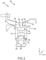
FIG. 3 illustrates a centering and damping assembly for use in a bearing compartment of a gas turbine engine, in accordance with various embodiments; -
FIG. 4 illustrates inclusion of an oil nozzle in a centering and damping assembly, in accordance with various embodiments; -
FIGS. 5A and 5B illustrate fan blade out features of a centering and damping assembly, in accordance with various embodiments; and -
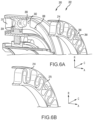
FIGS. 6A and 6B illustrate disassembly features of a centering and damping assembly, in accordance with various embodiments. - The detailed description of exemplary embodiments herein makes reference to the accompanying drawings, which show exemplary embodiments by way of illustration and their best mode. While these exemplary embodiments are described in sufficient detail to enable those skilled in the art to practice the inventions, it should be understood that other embodiments may be realized and that logical, chemical and mechanical changes may be made without departing from the scope of the inventions. Thus, the detailed description herein is presented for purposes of illustration only and not of limitation. For example, the steps recited in any of the method or process descriptions may be executed in any order and are not necessarily limited to the order presented. Furthermore, any reference to singular includes plural embodiments, and any reference to more than one component or step may include a singular embodiment or step. Also, any reference to attached, fixed, connected or the like may include permanent, removable, temporary, partial, full and/or any other possible attachment option. Additionally, any reference to without contact (or similar phrases) may also include reduced contact or minimal contact. Where used herein, the phrase "at least one of A or B" can include any of "A" only, "B" only, or "A and B."
- With reference to
FIG. 1 , agas turbine engine 20 is provided. As used herein, "aft" refers to the direction associated with the tail (e.g., the back end) of an aircraft, or generally, to the direction of exhaust of the gas turbine engine. As used herein, "forward" refers to the direction associated with the nose (e.g., the front end) of an aircraft, or generally, to the direction of flight or motion. As utilized herein, radially inward refers to the negative R direction and radially outward refers to the R direction. An A-R-C axis is shown throughout the drawings to illustrate the relative position of various components. - The
gas turbine engine 20 may be a two-spool turbofan that generally incorporates afan section 22, acompressor section 24, acombustor section 26 and aturbine section 28. In operation, thefan section 22 drives air along a bypass flow-path B while thecompressor section 24 drives air along a core flow-path C for compression and communication into thecombustor section 26 then expansion through theturbine section 28. Although depicted as a turbofangas turbine engine 20 herein, it should be understood that the concepts described herein are not limited to use with turbofans as the teachings may be applied to other types of turbine engines including three-spool architectures, geared turbofan architectures, and turboshaft or industrial gas turbines with one or more spools. - The
gas turbine engine 20 generally comprises alow speed spool 30 and ahigh speed spool 32 mounted for rotation about an engine central longitudinal axis X-X' relative to an enginestatic structure 36 via several bearing systems 38, 38-1, and 38-2. It should be understood that various bearing systems 38 at various locations may alternatively or additionally be provided, including for example, the bearing system 38, the bearing system 38-1, and the bearing system 38-2. - The
low speed spool 30 generally includes aninner shaft 40 that interconnects afan 42, a low pressure (or first)compressor section 44 and a low pressure (or second)turbine section 46. Theinner shaft 40 is connected to thefan 42 through a geared architecture 48 that can drive the fan shaft 98, and thus thefan 42, at a lower speed than thelow speed spool 30. The geared architecture 48 includes agear assembly 60 enclosed within a gear diffuser case 62. Thegear assembly 60 couples theinner shaft 40 to a rotating fan structure. - The
high speed spool 32 includes anouter shaft 50 that interconnects a high pressure (or second)compressor section 52 and the high pressure (or first) turbine section 54. Acombustor 56 is located between thehigh pressure compressor 52 and the high pressure turbine 54. A mid-turbine frame 57 of the enginestatic structure 36 is located generally between the high pressure turbine 54 and thelow pressure turbine 46. The mid-turbine frame 57 supports one or more bearing systems 38 in theturbine section 28. Theinner shaft 40 and theouter shaft 50 are concentric and rotate via the bearing systems 38 about the engine central longitudinal axis X-X', which is collinear with their longitudinal axes. As used herein, a "high pressure" compressor or turbine experiences a higher pressure than a corresponding "low pressure" compressor or turbine. - The core airflow C is compressed by the low
pressure compressor section 44 then thehigh pressure compressor 52, mixed and burned with fuel in thecombustor 56, then expanded over the high pressure turbine 54 and thelow pressure turbine 46. The mid-turbine frame 57 includes airfoils 59 which are in the core airflow path. Theturbines 46, 54 rotationally drive the respectivelow speed spool 30 andhigh speed spool 32 in response to the expansion. - The
gas turbine engine 20 is a high-bypass ratio geared aircraft engine. The bypass ratio of thegas turbine engine 20 may be greater than about six (6). The bypass ratio of thegas turbine engine 20 may also be greater than ten (10:1). The geared architecture 48 may be an epicyclic gear train, such as a star gear system (sun gear in meshing engagement with a plurality of star gears supported by a carrier and in meshing engagement with a ring gear) or other gear system. The geared architecture 48 may have a gear reduction ratio of greater than about 2.3 and thelow pressure turbine 46 may have a pressure ratio that is greater than about five (5). The diameter of thefan 42 may be significantly larger than that of the lowpressure compressor section 44, and thelow pressure turbine 46 may have a pressure ratio that is greater than about five (5:1). The pressure ratio of thelow pressure turbine 46 is measured prior to an inlet of thelow pressure turbine 46 as related to the pressure at the outlet of thelow pressure turbine 46. It should be understood, however, that the above parameters are exemplary of various embodiments of a suitable geared architecture engine and that the present disclosure contemplates other turbine engines including direct drive turbofans. - The next generation turbofan engines are designed for higher efficiency and use higher pressure ratios and higher temperatures in the
high pressure compressor 52 than are conventionally experienced. These higher operating temperatures and pressure ratios create operating environments that cause thermal loads that are higher than the thermal loads conventionally experienced, which may shorten the operational life of current components. - In various embodiments and referring to
FIGS. 2A ,2B , and2C , a centering and damping assembly, orassembly 100, for use in abearing compartment 102 of a gas turbine engine is shown. Theassembly 100 may provide various advantages over conventional centering and damping assemblies. For example, theassembly 100 may be more compact (i.e., utilize less volume) than conventional assemblies, and may include features that reduce an axial dimension of theassembly 100. Additionally, theassembly 100 may provide improved scavenging of damping fluid. Theassembly 100 may include various features that axially and circumferentially retain components of theassembly 100, thus reducing the likelihood of damage to any components. An oil nozzle may be included in theassembly 100 to further reduce space utilized in thebearing compartment 102. Theassembly 100 may include features that reduce the likelihood of damages during a fan blade out (FBO) event, and may further include features to facilitate disassembly of theassembly 100. For example, the assembly may be used in one or more of the bearing systems 38, 38-1, or 38-2 ofFIG. 1 . - The
assembly 100 may further include features, as discussed further below, that reduce the likelihood of undesirable vibration. For example, particularly if a corresponding engine is vibrating at a harmonic frequency of a spring of theassembly 100, the spring may undesirably amplify such vibrations. - The
assembly 100 may include apedestal 104, adamper 106 having adamper surface 108, a firstannular spring 112, and a secondannular spring 114. Thebearing compartment 102 may include abearing support 122, a bearingouter race 124, androllers 126. A shaft may be located radially inward from therollers 126 and may rotate relative to theassembly 100. - A
gap 110 may exist between thedamper surface 108 and thepedestal 104 and may receive a damping fluid to form a dampingassembly 116. In response to an increase in radial velocity of the shaft, force may be applied radially outward on theassembly 100. The force may be dampened by the dampingassembly 116 and theannular springs - The
pedestal 104 may define one ormore scavenging hole 128 in fluid communication with the damping fluid. In that regard, the scavenginghole 128 may scavenge the damping fluid from thegap 110. The presence of the scavenginghole 128 may allow theannular springs support 122, reducing a total size of theassembly 100. - In various embodiments, the
bearing support 122 and thepedestal 104 may be formed monolithically. The embodiment illustrated inFIGS. 2A ,2B , and2C may be utilized in a gas turbine engine in which theassembly 100 may be installed or assembled from the axially forward direction and the axially aft direction. Use of a monolithic component as thebearing support 122 and thepedestal 104 reduces a total part count, thus reducing a manufacturing cost and complexity of assembly. - In various embodiments, the
damper 106 and the bearingouter race 124 may be separate and may be formed using different materials. For example, thedamper 106 may be or include a titanium, and the bearingouter race 124 may include a steel. It may be desirable for the bearingouter race 124 to include a steel, however, titanium and titanium alloys (e.g., grade 5 titanium, or another relatively light metal) used in thedamper 106 may reduce a total mass of theassembly 100 as titanium has a lower density. - It may be desirable to axially and circumferentially retain the various components of the
assembly 100. In that regard, various features may function as one or more of an anti-rotation feature or an axial retaining feature. For example, the anti-rotation feature may resist rotation of theannular springs pedestal 104 or thedamper 106. - In various embodiments, the anti-rotation feature may include a
spring castellation 134 defined by the first annular spring 112 (or the second annular spring 114), and adamper castellation 136 defined by thedamper 106. Thecastellations first spring 112 relative to thedamper 106 or thepedestal 104. In various embodiments, thespring castellation 134 may engage with a pedestal castellation instead of, or in addition to, thedamper castellation 136. - In various embodiments, the anti-rotation feature may include a
fastener 138 configured to extend through a portion of one or bothannular springs fastener 138 may provide axial retention of the components and may also be referred to as an axial retention feature. In various embodiments, thefastener 138 may include a rivet, a bolt, or the like. In various embodiments, ahelicoil 140 may be received by an annular spring (such as the first annular spring 112) such that thefastener 138 extends through the secondannular spring 114 and thepedestal 104 and is received by thehelicoil 140 in order to fasten theannular springs pedestal 104. - In various embodiments, the anti-rotation feature may include one or
more pins 144 configured to retain one or more of theannular springs pedestal 104 or thedamper 106. For example, the secondannular spring 114 may define aboss 146 with a hole that receives thepin 144, and thepedestal 104 may include a matching boss with a hole that likewise receives thepin 144. In that regard, thepin 144 may resist rotation of the secondannular spring 114 relative to thepedestal 104. - In various embodiments, the
annular springs inner ring 118, anouter ring 120 located radially outward from theinner ring 118, and acompressible portion 119 located radially between theinner ring 118 and theouter ring 120 and configured to be compressed. As will be discussed below, it may be desirable to resist rotation of theinner ring 118 relative to theouter ring 120 in order to reduce the likelihood of damage to theannular springs - The annular springs 112, 114 may be designed to be asymmetric in order to reduce undesirable vibration of the
springs compressible portion 119 of theannular springs inner ring 118, in theouter ring 120, or in at least one of thecompressible portion 119, theinner ring 118, or theouter ring 120. Such asymmetry may be introduced in any of a number of manners. The asymmetry may be introduced by making the first annular spring 112 (e.g., the compressible portion of the first annular spring 112) have different features from the second annular spring 114 (e.g., thecompressible portion 119 of the second annular spring). For example, the firstannular spring 112 may be formed at least partially using a different material from the secondannular spring 114 to make the mass of the firstannular spring 112 different than the mass of the secondannular spring 114. - As yet another example, the first
annual spring 112 may have athickness 154 that is at least partially different from athickness 156 of the secondannular spring 114. For example, thethickness 156 may correspond to each of thecompressible portion 119, theinner ring 118, and theouter ring 120 - As another example, the first
annular spring 112 may have a different quantity of turns perunit area 158 than the secondannular spring 114. For example, the compressible portion of the firstannular spring 112 may have three turns in thearea 158 and thecompressible portion 119 of the secondannular spring 114 may have four turns in the area 170. - As another example, the first
annular spring 112 may have a circumferential length that is different than a circumferential length of the secondannular spring 114. - As yet another example, the first
annular spring 112 may have a different shape relative to the secondannular spring 114. For example, the compressible portion of the firstannular spring 112 may have angular turns whereas thecompressible portion 119 of the secondannular spring 114 may have more rounded turns. - As yet another example, the first
annular spring 112 may be radially offset (e.g., radially inward or radially outward) relative to acenterline 130 of the secondannular spring 114. In various embodiments, both of the firstannular spring 112 and the secondannular spring 114 may be offset relative to thecenterline 130. - As yet another example, the first
annular spring 112 may be angularly offset relative to the secondannular spring 114 to introduce the asymmetry of the firstannular spring 112 relative to the secondannular spring 114. - In various embodiments, the asymmetry may be introduced in only one of the first
annular spring 112 or the secondannular spring 114, or each of the firstannular spring 112 and the secondannular spring 114 may have asymmetry introduced in different manners. For example, a first portion 172 of the firstannular spring 112 may be formed from a different material than a second portion 174 of the firstannular spring 112. The different materials may have different densities in order to introduce the asymmetry. - As another example, the first portion 172 of the first
annular spring 112 may be formed to have a thickness 176 that is different than a thickness 178 of the second portion 174 of the firstannular spring 112. Such difference in thickness may introduce asymmetry in the firstannular spring 112. - As yet another example, the first portion 172 of the first
annular spring 112 may have a different quantity of turns than the second portion 174 of the firstannular spring 112. Such difference in quantity of turns per unit area may introduce asymmetry within the firstannular spring 112. - As yet another example, the first portion 172 of the first
annular spring 112 may be formed to have a different length than the second portion 174 of the firstannular spring 112. This different length may introduce asymmetry within the firstannular spring 112. - As yet another example, a shape of the first portion 172 of the first annular spring may be different than a shape of the second portion 174 of the first annular spring. For example, the turns within the first portion 172 may have a more angular shape relative to the turns of the second portion 174. Such difference in shape may introduce asymmetry within the first
annular spring 112. - In various embodiments, one or both of the first
annular spring 112 and the secondannular spring 114 may be asymmetrical and both the axial direction and in the circumferential direction. For example, the firstannular spring 112 may be formed asymmetrically relative to the second annular spring 114 (causing axial asymmetry), and the firstannular spring 112 may have a greater quantity of turns in the first portion 172 than in the second portion 174 (causing circumferential asymmetry). - Referring now to
FIG. 3 , anotherassembly 200 may be used in abearing compartment 202 and may provide centering and damping for a bearing assembly. The components of theassembly 200 may be similar to the components of theassembly 100 ofFIG. 2A . In particular, theassembly 200 may include apedestal 204, adamper 206, a firstannular spring 212, a secondannular spring 214, abearing support 222 separate from thepedestal 204, a bearing outer race 224, androllers 226. - The
assembly 200 may differ from theassembly 100 ofFIG. 2A in that theassembly 100 is designed to be assembled from a single direction (i.e., from an axially forward direction or from an axially aft direction). In that regard, acoupling feature 250 may be coupled to one or both of theannular springs pedestal 204 or thedamper 206, and may resist rotation of theannular springs pedestal 204 or thedamper 206. Thecoupling feature 250 may further resist axial separation of theannular springs pedestal 204 or thedamper 206, such as by an interface between a bolt and nut. Thecoupling feature 250 may include one or more of a pin or castellations (similar to thecastellations 134 shown inFIG. 2A ). Thecoupling feature 250 may be located radially outward from thedamper 206. For example, thecoupling feature 250 may include a first feature to couple thebearing support 222 to the firstannular spring 212, a second feature to couple the firstannular spring 212 to thedamper 206, and a third feature to couple thedamper 206 to the secondannular spring 214. - A
second coupling feature 252 may be coupled to one or both of theannular springs pedestal 204 or thedamper 206, and may resist rotation of theannular springs pedestal 204 or thedamper 206. Thecoupling feature 252 may further resist axial separation of theannular springs pedestal 204 or thedamper 206. Thecoupling feature 252 may include one or more of a retaining ring, a nut, or castellations (similar to the castellations shown inFIG. 2A ). Thecoupling feature 252 may be located radially inward from thepedestal 204. For example, thecoupling feature 252 may be used to couple theannular springs damper 206 and the bearing outer race 224. - A
third coupling feature 254 may be coupled to one or both of theannular springs pedestal 204 or thedamper 206, and may resist rotation of theannular springs pedestal 204 or thedamper 206. Thecoupling feature 254 may further may resist axial separation of theannular springs pedestal 204 or thedamper 206. Thecoupling feature 254 may include one or more of a nut or a retaining ring. Thecoupling feature 254 may be located radially outward from thedamper 206. For example, thethird coupling feature 254 may be used to couple theannular springs pedestal 204. - In order to assemble the
assembly 200, thebearing support 222, the bearing outer race 224, thedamper 206, and the firstannular spring 212 may be coupled together. These components, after being coupled together, may be positioned in place in the gas turbine engine. Afterwards, these components may be locked in place using one or more of pins, castellations, or nuts. Next, thepedestal 204 may be inserted adjacent to the firstannular spring 212, and the secondannular spring 214 may be inserted adjacent to thepedestal 204. The secondannular spring 214 may then be coupled to one or both of thedamper 206 or thepedestal 204, and thecoupling feature 254 may be fastened to couple theassembly 200 together. - In various embodiments, the first
annular spring 212, thepedestal 204, and the secondannular spring 214 may be coupled with abore 230 of thebearing support 222 using an interference fit. In that regard, thebore 230 of thebearing support 222 may have a "stepped" design. That is, thebore 230 may have afirst portion 232 aligned with the secondannular spring 214, asecond portion 234 aligned with thepedestal 204, and athird portion 236 aligned with the firstannular spring 212. Thesecond portion 234 may extend farther outward in the radial direction than thethird portion 236, and thefirst portion 232 may extend farther outward than thesecond portion 234. In various embodiments, the difference in diameter of the portions of thebore 230 may be between 0.001 inches and .1 inches (0.0254 millimeters (mm) and 2.54 mm), between 0.003 inches and 0.07 inches (0.0762 mm and 1.78 mm), or between 0.004 inches and 0.05 inches (0.102 mm and 1.27 mm). In that regard, the firstannular spring 212, thepedestal 204, and the secondannular spring 214 may each have a diameter that facilitates an interference fit within the corresponding portion of thebore 230. The secondannular spring 214 may be inserted first, then thepedestal 204, and finally the firstannular spring 212. This stepped design may reduce undesirable contact of components during the installation and disassembly. - Referring now to
FIG. 4 , anoil nozzle 150 may be included in theassembly 100. In particular, theoil nozzle 150 may be coupled to thepedestal 104, such as by using thefastener 138 ofFIG. 2C , or using afastener 300, and may receive oil or another lubricant via a pathway defined by thepedestal 104. In various embodiments, thefastener 138 may extend through the secondannular spring 114, theoil nozzle 150, and thepedestal 104, or through theoil nozzle 150 and thepedestal 104 without extending through the secondannular spring 114. Theoil nozzle 150 may provide lubricant to thebearing compartment 102. The secondannular spring 114 may include or define one ormore window 152. During assembly, theoil nozzle 150 may be positioned through thewindow 152 such that theoil nozzle 150 extends axially forward (or axially aft) of the secondannular spring 114. - In various embodiments and as mentioned above, it may be desirable to resist rotation of the
inner ring 118 relative to theouter ring 120 in order to reduce the likelihood of damage to the secondannular spring 114 during a fan blade out (FBO) event. In that regard, theassembly 100 may include various features to resist this rotation. - For example and referring to
FIG. 5A , thepedestal 104 may include or define apedestal lug 160, and theinner ring 118 of the secondannular spring 114 may include or define aslot 162. Thepedestal lug 160 may be received by theslot 162 in order to resist rotation of theinner ring 118 relative to thepedestal 104, which likewise resists rotation of theinner ring 118 relative to theouter ring 120. - As another example, the
bearing support 122 may include or define asupport lug 164. Thesupport lug 164 may be received by theslot 162, and the interface between thesupport lug 164 and theslot 162 may resist rotation of theinner ring 118 relative to thebearing support 122, which likewise reduces rotation of theinner ring 118 relative to theouter ring 120. - In various embodiments, only one of the
pedestal lug 160 or thesupport lug 164 may be used in theassembly 100 as an anti-rotation feature. - As yet another example and referring to
FIG. 5B , the secondannular spring 114 may include anouter ring lug 166 extending from theouter ring 120 towards theinner ring 118. Similarly, theinner ring 118 may define, include, or be coupled to aslot 168. Theouter ring lug 166 may be received by theslot 168 such that the interface between theouter ring lug 166 and theslot 168 resists rotation of theinner ring 118 relative to theouter ring 120. - Although the features illustrated in
FIGS. 4 ,5A, and 5B are shown included in theassembly 100 ofFIG. 2A , they may likewise be included in theassembly 200 ofFIG. 3 . - The
assembly 100 ofFIG. 2A (or theassembly 200 ofFIG. 3 ) may include various features to facilitate disassembly. For example and referring toFIGS. 6A and 6B , thepedestal 204 of theassembly 200 may include or define apedestal boss 260 which defines a threadedhole 262. Likewise, the secondannular spring 214 may define or include aspring boss 264 which defines a threadedhole 266. Additionally, thepedestal 204 may define or include a hole with ahelicoil 268. A disassembly tool having a threaded tip may be received by any one or more of the threadedhole 262, the threadedhole 266, or thehelicoil 268 and may be actuated away from the firstannular spring 212 in order to remove the respective components from theassembly 200. - As another example, one or more of the second
annular spring 214 or thepedestal 204 may define or include adisassembly boss 270. A puller tool, such as pliers, may engage thedisassembly boss 270 and may be actuated in order to remove the respective components. - Benefits, other advantages, and solutions to problems have been described herein with regard to specific embodiments. Furthermore, the connecting lines shown in the various figures contained herein are intended to represent exemplary functional relationships and/or physical couplings between the various elements. It should be noted that many alternative or additional functional relationships or physical connections may be present in a practical system. However, the benefits, advantages, solutions to problems, and any elements that may cause any benefit, advantage, or solution to occur or become more pronounced are not to be construed as critical, required, or essential features or elements of the inventions. The scope of the invention is accordingly to be limited by nothing other than the appended claims, in which reference to an element in the singular is not intended to mean "one and only one" unless explicitly so stated, but rather "one or more." Moreover, where a phrase similar to "at least one of A, B, or C" is used in the claims, it is intended that the phrase be interpreted to mean that A alone may be present in an embodiment, B alone may be present in an embodiment, C alone may be present in an embodiment, or that any combination of the elements A, B and C may be present in a single embodiment; for example, A and B, A and C, B and C, or A and B and C. Different cross-hatching is used throughout the figures to denote different parts but not necessarily to denote the same or different materials.
- Systems, methods and apparatus are provided herein. In the detailed description herein, references to "one embodiment", "an embodiment", "various embodiments", etc., indicate that the embodiment described may include a particular feature, structure, or characteristic, but every embodiment may not necessarily include the particular feature, structure, or characteristic. Moreover, such phrases are not necessarily referring to the same embodiment. Further, when a particular feature, structure, or characteristic is described in connection with an embodiment, it is submitted that it is within the knowledge of one skilled in the art to affect such feature, structure, or characteristic in connection with other embodiments whether or not explicitly described. After reading the description, it will be apparent to one skilled in the relevant art(s) how to implement the disclosure in alternative embodiments.
- Furthermore, no element, component, or method step in the present disclosure is intended to be dedicated to the public regardless of whether the element, component, or method step is explicitly recited in the claims. As used herein, the terms "comprises", "comprising", or any other variation thereof, are intended to cover a non-exclusive inclusion, such that a process, method, article, or apparatus that comprises a list of elements does not include only those elements but may include other elements not expressly listed or inherent to such process, method, article, or apparatus.
embodiment; for example, A and B, A and C, B and C, or A and B and C. Different cross-hatching is used throughout the figures to denote different parts but not necessarily to denote the same or different materials. - Systems, methods and apparatus are provided herein. In the detailed description herein, references to "one embodiment", "an embodiment", "various embodiments", etc., indicate that the embodiment described may include a particular feature, structure, or characteristic, but every embodiment may not necessarily include the particular feature, structure, or characteristic. Moreover, such phrases are not necessarily referring to the same embodiment. Further, when a particular feature, structure, or characteristic is described in connection with an embodiment, it is submitted that it is within the knowledge of one skilled in the art to affect such feature, structure, or characteristic in connection with other embodiments whether or not explicitly described. After reading the description, it will be apparent to one skilled in the relevant art(s) how to implement the disclosure in alternative embodiments.
Claims (11)
- An assembly (100) for use in a bearing compartment (102) having an axis (X-X'), the assembly (100) comprising:a bearing outer race (124) configured to be located in the bearing compartment (102); andat least one annular spring (112, 114) positioned in the bearing outer race (124) and being asymmetric in the axial direction and the circumferential direction relative to the axis (X-X') to reduce the likelihood of amplification of vibration experienced by the at least one annular spring (112, 114).
- The assembly (100) of claim 1, wherein the annular spring (112, 114) is configured for use as a centering spring.
- The assembly (100) of claim 1 or 2, wherein the at least one annular spring (112, 114) is formed to have the asymmetry by adjusting a material in at least a portion of the at least one annular spring (112, 114).
- The assembly (100) of any preceding claim, wherein the at least one annular spring (112, 114) is formed to have the asymmetry by adjusting a thickness (154) in at least a portion of the at least one annular spring (112, 114).
- The assembly (100) of any preceding claim, wherein the at least one annular spring (112, 114) is formed to have the asymmetry by adjusting a quantity of turns per unit area (158, 170) in at least a portion of the at least one annular spring (112, 114).
- The assembly (100) of any preceding claim, wherein the at least one annular spring (112, 114) is formed to have the asymmetry by adjusting a length of at least a portion of the at least one annular spring (112, 114).
- The assembly (100) of any preceding claim, wherein the at least one annular spring (112, 114) is formed to have the asymmetry by adjusting a shape of at least a portion of the at least one annular spring (112, 114).
- The assembly (100) of any preceding claim, wherein the at least one annular spring includes a first annular spring (112) and a second annular spring (114), and the at least one annular spring is formed to have the asymmetry by adjusting an angular offset of the first annular spring (112) relative to the second annular spring (114).
- The assembly (100) of any preceding claim, wherein the at least one annular spring includes a first annular spring (112) and a second annular spring (114), and the at least one annular spring is formed to have the asymmetry by at least one of adjusting a material of the first annular spring (112) relative to the second annular spring (114), adjusting a thickness of the of the first annular spring (112) relative to the second annular spring (114), adjusting a quantity of turns per unit area (158) of the first annular spring (112) relative to the second annular spring (114), adjusting a length of the first annular spring (112) relative to the second annular spring (114), or adjusting a shape of the first annular spring (112) relative to the second annular spring (114).
- An assembly (100) for use in a bearing compartment (102) having an axis, the assembly (100) comprising:a pedestal (104);a damper (106) having a damper surface (108) configured to be positioned adjacent to the pedestal (104) and separated from the pedestal (104) by a gap (110), the gap (110) receiving a damping fluid to form a damping assembly (116) between the damper (106) and the pedestal (104); andan annular spring (112) positioned axially forward or axially aft of the pedestal (104) and being at least one of radially offset relative to a second annular spring (114) or asymmetric in the axial direction and the circumferential direction relative to the axis (X-X') to reduce the likelihood of amplification of vibration experienced by the annular spring (112).
- The assembly (100) of claim 10, wherein the annular spring (112, 114) is formed to have the asymmetry by at least one of:adjusting a thickness in at least a portion of the annular spring (112, 114);adjusting a quantity of turns per unit area (158, 170) in at least a portion of the annular spring (112, 114);adjusting a length of at least a portion of the annular spring (112, 114); oradjusting a shape of at least a portion of the annular spring (112, 114).
Applications Claiming Priority (1)
| Application Number | Priority Date | Filing Date | Title |
|---|---|---|---|
| US17/162,875 US11542835B2 (en) | 2021-01-29 | 2021-01-29 | Asymmetry in annular centering spring |
Publications (2)
| Publication Number | Publication Date |
|---|---|
| EP4036428A1 EP4036428A1 (en) | 2022-08-03 |
| EP4036428B1 true EP4036428B1 (en) | 2023-12-06 |
Family
ID=80122147
Family Applications (1)
| Application Number | Title | Priority Date | Filing Date |
|---|---|---|---|
| EP22153759.0A Active EP4036428B1 (en) | 2021-01-29 | 2022-01-27 | Asymmetry in annular centering spring |
Country Status (2)
| Country | Link |
|---|---|
| US (1) | US11542835B2 (en) |
| EP (1) | EP4036428B1 (en) |
Families Citing this family (1)
| Publication number | Priority date | Publication date | Assignee | Title |
|---|---|---|---|---|
| US11971054B2 (en) * | 2020-10-19 | 2024-04-30 | General Electric Company | Damping device for damping shaft vibration |
Family Cites Families (13)
| Publication number | Priority date | Publication date | Assignee | Title |
|---|---|---|---|---|
| US5230787A (en) * | 1991-12-30 | 1993-07-27 | Xerox Corporation | Spring and process for making a spring for a fluid bearing by electroforming |
| US8834027B2 (en) | 2011-01-13 | 2014-09-16 | Fouad Y. Zeidan | Damper having modular flexible ligaments and variable gaps |
| US20060204153A1 (en) * | 2005-03-10 | 2006-09-14 | Honeywell International Inc. | Compact resilient anisotropic support for bearing |
| DE202007012052U1 (en) | 2007-08-29 | 2009-01-08 | Oerlikon Leybold Vacuum Gmbh | Turbo molecular pump |
| US8083413B2 (en) * | 2007-10-23 | 2011-12-27 | General Electric Company | Compliant hybrid gas journal bearing using integral wire mesh dampers |
| DE102013206101A1 (en) | 2013-04-08 | 2014-10-30 | Schaeffler Technologies Gmbh & Co. Kg | Bearing ring and damping sleeve |
| DE102013210215A1 (en) | 2013-06-03 | 2014-12-04 | Schaeffler Technologies Gmbh & Co. Kg | Bearing arrangement with a fishing camp |
| DE102013213172A1 (en) * | 2013-07-04 | 2015-01-08 | Bosch Mahle Turbo Systems Gmbh & Co. Kg | turbocharger |
| US9745992B2 (en) | 2015-08-30 | 2017-08-29 | Honeywell International Inc. | Turbocharger bearing damper assembly |
| US9926975B2 (en) * | 2016-03-22 | 2018-03-27 | United Technologies Corporation | Centering spring and damper assembly |
| US9879720B2 (en) | 2016-05-05 | 2018-01-30 | General Electric Company | Bearing damper with external support spring systems and methods |
| US10753391B1 (en) | 2019-04-05 | 2020-08-25 | Raytheon Technologies Corporation | Compact centering spring configuration, retention, and bladeout features |
| US10794222B1 (en) * | 2019-08-14 | 2020-10-06 | General Electric Company | Spring flower ring support assembly for a bearing |
-
2021
- 2021-01-29 US US17/162,875 patent/US11542835B2/en active Active
-
2022
- 2022-01-27 EP EP22153759.0A patent/EP4036428B1/en active Active
Also Published As
| Publication number | Publication date |
|---|---|
| US20220243616A1 (en) | 2022-08-04 |
| EP4036428A1 (en) | 2022-08-03 |
| US11542835B2 (en) | 2023-01-03 |
Similar Documents
| Publication | Publication Date | Title |
|---|---|---|
| EP3719266A1 (en) | Assembly for a bearing compartment of a gas turbine engine | |
| US8262353B2 (en) | Decoupler system for rotor assemblies | |
| US8747054B2 (en) | Bearing system for gas turbine engine | |
| US7739866B2 (en) | Turbofan case and method of making | |
| EP3036417B1 (en) | Bearing system for gas turbine engine | |
| US9869205B2 (en) | Bearing outer race retention during high load events | |
| US6325546B1 (en) | Fan assembly support system | |
| US7793488B2 (en) | Turbofan case and method of making | |
| EP2565395B1 (en) | Tie rod for a gas turbine engine | |
| US10392969B2 (en) | Moment accommodating fastener assembly | |
| US20160201793A1 (en) | Lightweight and compliant journal pin | |
| US20100226786A1 (en) | Nose cone assembly | |
| US20140317926A1 (en) | Front centerbody support for a gas turbine engine | |
| US4249859A (en) | Preloaded engine inlet shroud | |
| US9976443B2 (en) | Turbofan engine assembly methods | |
| EP3620619A1 (en) | Turbine exhaust structure for a gas turbine engine | |
| EP4036428B1 (en) | Asymmetry in annular centering spring | |
| EP3546726A1 (en) | Turbofan engine assembly methods | |
| US11485508B2 (en) | Turbine engine assembly and method of manufacturing thereof | |
| EP3246517B1 (en) | Fastener openings for stress distribution | |
| EP4137674A1 (en) | Deformable bumper for a rotating structure of a turbine engine | |
| EP3712391B1 (en) | Strut dampening assembly and method of making same | |
| EP3348785A1 (en) | Anti-rotation lock for threaded in place nosecone or spinner | |
| EP4299882B1 (en) | Bearing carrier support with reduced axial length | |
| US11555408B2 (en) | Device for attaching blades in a contra-rotating turbine |
Legal Events
| Date | Code | Title | Description |
|---|---|---|---|
| PUAI | Public reference made under article 153(3) epc to a published international application that has entered the european phase |
Free format text: ORIGINAL CODE: 0009012 |
|
| STAA | Information on the status of an ep patent application or granted ep patent |
Free format text: STATUS: THE APPLICATION HAS BEEN PUBLISHED |
|
| AK | Designated contracting states |
Kind code of ref document: A1 Designated state(s): AL AT BE BG CH CY CZ DE DK EE ES FI FR GB GR HR HU IE IS IT LI LT LU LV MC MK MT NL NO PL PT RO RS SE SI SK SM TR |
|
| STAA | Information on the status of an ep patent application or granted ep patent |
Free format text: STATUS: REQUEST FOR EXAMINATION WAS MADE |
|
| 17P | Request for examination filed |
Effective date: 20230201 |
|
| RBV | Designated contracting states (corrected) |
Designated state(s): AL AT BE BG CH CY CZ DE DK EE ES FI FR GB GR HR HU IE IS IT LI LT LU LV MC MK MT NL NO PL PT RO RS SE SI SK SM TR |
|
| GRAP | Despatch of communication of intention to grant a patent |
Free format text: ORIGINAL CODE: EPIDOSNIGR1 |
|
| STAA | Information on the status of an ep patent application or granted ep patent |
Free format text: STATUS: GRANT OF PATENT IS INTENDED |
|
| INTG | Intention to grant announced |
Effective date: 20230628 |
|
| GRAS | Grant fee paid |
Free format text: ORIGINAL CODE: EPIDOSNIGR3 |
|
| RAP3 | Party data changed (applicant data changed or rights of an application transferred) |
Owner name: RTX CORPORATION |
|
| GRAA | (expected) grant |
Free format text: ORIGINAL CODE: 0009210 |
|
| STAA | Information on the status of an ep patent application or granted ep patent |
Free format text: STATUS: THE PATENT HAS BEEN GRANTED |
|
| AK | Designated contracting states |
Kind code of ref document: B1 Designated state(s): AL AT BE BG CH CY CZ DE DK EE ES FI FR GB GR HR HU IE IS IT LI LT LU LV MC MK MT NL NO PL PT RO RS SE SI SK SM TR |
|
| REG | Reference to a national code |
Ref country code: GB Ref legal event code: FG4D |
|
| REG | Reference to a national code |
Ref country code: DE Ref legal event code: R096 Ref document number: 602022001180 Country of ref document: DE |
|
| REG | Reference to a national code |
Ref country code: CH Ref legal event code: EP |
|
| REG | Reference to a national code |
Ref country code: IE Ref legal event code: FG4D |
|
| REG | Reference to a national code |
Ref country code: LT Ref legal event code: MG9D |
|
| PG25 | Lapsed in a contracting state [announced via postgrant information from national office to epo] |
Ref country code: GR Free format text: LAPSE BECAUSE OF FAILURE TO SUBMIT A TRANSLATION OF THE DESCRIPTION OR TO PAY THE FEE WITHIN THE PRESCRIBED TIME-LIMIT Effective date: 20240307 |
|
| REG | Reference to a national code |
Ref country code: NL Ref legal event code: MP Effective date: 20231206 |
|
| PG25 | Lapsed in a contracting state [announced via postgrant information from national office to epo] |
Ref country code: LT Free format text: LAPSE BECAUSE OF FAILURE TO SUBMIT A TRANSLATION OF THE DESCRIPTION OR TO PAY THE FEE WITHIN THE PRESCRIBED TIME-LIMIT Effective date: 20231206 |
|
| PG25 | Lapsed in a contracting state [announced via postgrant information from national office to epo] |
Ref country code: ES Free format text: LAPSE BECAUSE OF FAILURE TO SUBMIT A TRANSLATION OF THE DESCRIPTION OR TO PAY THE FEE WITHIN THE PRESCRIBED TIME-LIMIT Effective date: 20231206 |
|
| PG25 | Lapsed in a contracting state [announced via postgrant information from national office to epo] |
Ref country code: LT Free format text: LAPSE BECAUSE OF FAILURE TO SUBMIT A TRANSLATION OF THE DESCRIPTION OR TO PAY THE FEE WITHIN THE PRESCRIBED TIME-LIMIT Effective date: 20231206 Ref country code: GR Free format text: LAPSE BECAUSE OF FAILURE TO SUBMIT A TRANSLATION OF THE DESCRIPTION OR TO PAY THE FEE WITHIN THE PRESCRIBED TIME-LIMIT Effective date: 20240307 Ref country code: ES Free format text: LAPSE BECAUSE OF FAILURE TO SUBMIT A TRANSLATION OF THE DESCRIPTION OR TO PAY THE FEE WITHIN THE PRESCRIBED TIME-LIMIT Effective date: 20231206 Ref country code: BG Free format text: LAPSE BECAUSE OF FAILURE TO SUBMIT A TRANSLATION OF THE DESCRIPTION OR TO PAY THE FEE WITHIN THE PRESCRIBED TIME-LIMIT Effective date: 20240306 |
|
| PGFP | Annual fee paid to national office [announced via postgrant information from national office to epo] |
Ref country code: DE Payment date: 20231219 Year of fee payment: 3 |
|
| REG | Reference to a national code |
Ref country code: AT Ref legal event code: MK05 Ref document number: 1638668 Country of ref document: AT Kind code of ref document: T Effective date: 20231206 |
|
| PG25 | Lapsed in a contracting state [announced via postgrant information from national office to epo] |
Ref country code: NL Free format text: LAPSE BECAUSE OF FAILURE TO SUBMIT A TRANSLATION OF THE DESCRIPTION OR TO PAY THE FEE WITHIN THE PRESCRIBED TIME-LIMIT Effective date: 20231206 |
|
| PG25 | Lapsed in a contracting state [announced via postgrant information from national office to epo] |
Ref country code: SE Free format text: LAPSE BECAUSE OF FAILURE TO SUBMIT A TRANSLATION OF THE DESCRIPTION OR TO PAY THE FEE WITHIN THE PRESCRIBED TIME-LIMIT Effective date: 20231206 Ref country code: RS Free format text: LAPSE BECAUSE OF FAILURE TO SUBMIT A TRANSLATION OF THE DESCRIPTION OR TO PAY THE FEE WITHIN THE PRESCRIBED TIME-LIMIT Effective date: 20231206 Ref country code: NO Free format text: LAPSE BECAUSE OF FAILURE TO SUBMIT A TRANSLATION OF THE DESCRIPTION OR TO PAY THE FEE WITHIN THE PRESCRIBED TIME-LIMIT Effective date: 20240306 Ref country code: NL Free format text: LAPSE BECAUSE OF FAILURE TO SUBMIT A TRANSLATION OF THE DESCRIPTION OR TO PAY THE FEE WITHIN THE PRESCRIBED TIME-LIMIT Effective date: 20231206 Ref country code: LV Free format text: LAPSE BECAUSE OF FAILURE TO SUBMIT A TRANSLATION OF THE DESCRIPTION OR TO PAY THE FEE WITHIN THE PRESCRIBED TIME-LIMIT Effective date: 20231206 Ref country code: HR Free format text: LAPSE BECAUSE OF FAILURE TO SUBMIT A TRANSLATION OF THE DESCRIPTION OR TO PAY THE FEE WITHIN THE PRESCRIBED TIME-LIMIT Effective date: 20231206 |
|
| PGFP | Annual fee paid to national office [announced via postgrant information from national office to epo] |
Ref country code: FR Payment date: 20240123 Year of fee payment: 3 |
|
| PG25 | Lapsed in a contracting state [announced via postgrant information from national office to epo] |
Ref country code: IS Free format text: LAPSE BECAUSE OF FAILURE TO SUBMIT A TRANSLATION OF THE DESCRIPTION OR TO PAY THE FEE WITHIN THE PRESCRIBED TIME-LIMIT Effective date: 20240406 |
|
| PG25 | Lapsed in a contracting state [announced via postgrant information from national office to epo] |
Ref country code: AT Free format text: LAPSE BECAUSE OF FAILURE TO SUBMIT A TRANSLATION OF THE DESCRIPTION OR TO PAY THE FEE WITHIN THE PRESCRIBED TIME-LIMIT Effective date: 20231206 Ref country code: CZ Free format text: LAPSE BECAUSE OF FAILURE TO SUBMIT A TRANSLATION OF THE DESCRIPTION OR TO PAY THE FEE WITHIN THE PRESCRIBED TIME-LIMIT Effective date: 20231206 |
|
| PG25 | Lapsed in a contracting state [announced via postgrant information from national office to epo] |
Ref country code: SK Free format text: LAPSE BECAUSE OF FAILURE TO SUBMIT A TRANSLATION OF THE DESCRIPTION OR TO PAY THE FEE WITHIN THE PRESCRIBED TIME-LIMIT Effective date: 20231206 |
|
| PG25 | Lapsed in a contracting state [announced via postgrant information from national office to epo] |
Ref country code: SM Free format text: LAPSE BECAUSE OF FAILURE TO SUBMIT A TRANSLATION OF THE DESCRIPTION OR TO PAY THE FEE WITHIN THE PRESCRIBED TIME-LIMIT Effective date: 20231206 Ref country code: SK Free format text: LAPSE BECAUSE OF FAILURE TO SUBMIT A TRANSLATION OF THE DESCRIPTION OR TO PAY THE FEE WITHIN THE PRESCRIBED TIME-LIMIT Effective date: 20231206 Ref country code: RO Free format text: LAPSE BECAUSE OF FAILURE TO SUBMIT A TRANSLATION OF THE DESCRIPTION OR TO PAY THE FEE WITHIN THE PRESCRIBED TIME-LIMIT Effective date: 20231206 Ref country code: IT Free format text: LAPSE BECAUSE OF FAILURE TO SUBMIT A TRANSLATION OF THE DESCRIPTION OR TO PAY THE FEE WITHIN THE PRESCRIBED TIME-LIMIT Effective date: 20231206 Ref country code: IS Free format text: LAPSE BECAUSE OF FAILURE TO SUBMIT A TRANSLATION OF THE DESCRIPTION OR TO PAY THE FEE WITHIN THE PRESCRIBED TIME-LIMIT Effective date: 20240406 Ref country code: EE Free format text: LAPSE BECAUSE OF FAILURE TO SUBMIT A TRANSLATION OF THE DESCRIPTION OR TO PAY THE FEE WITHIN THE PRESCRIBED TIME-LIMIT Effective date: 20231206 Ref country code: CZ Free format text: LAPSE BECAUSE OF FAILURE TO SUBMIT A TRANSLATION OF THE DESCRIPTION OR TO PAY THE FEE WITHIN THE PRESCRIBED TIME-LIMIT Effective date: 20231206 Ref country code: AT Free format text: LAPSE BECAUSE OF FAILURE TO SUBMIT A TRANSLATION OF THE DESCRIPTION OR TO PAY THE FEE WITHIN THE PRESCRIBED TIME-LIMIT Effective date: 20231206 |
|
| PG25 | Lapsed in a contracting state [announced via postgrant information from national office to epo] |
Ref country code: PL Free format text: LAPSE BECAUSE OF FAILURE TO SUBMIT A TRANSLATION OF THE DESCRIPTION OR TO PAY THE FEE WITHIN THE PRESCRIBED TIME-LIMIT Effective date: 20231206 Ref country code: PT Free format text: LAPSE BECAUSE OF FAILURE TO SUBMIT A TRANSLATION OF THE DESCRIPTION OR TO PAY THE FEE WITHIN THE PRESCRIBED TIME-LIMIT Effective date: 20240408 |
|
| PG25 | Lapsed in a contracting state [announced via postgrant information from national office to epo] |
Ref country code: PT Free format text: LAPSE BECAUSE OF FAILURE TO SUBMIT A TRANSLATION OF THE DESCRIPTION OR TO PAY THE FEE WITHIN THE PRESCRIBED TIME-LIMIT Effective date: 20240408 Ref country code: PL Free format text: LAPSE BECAUSE OF FAILURE TO SUBMIT A TRANSLATION OF THE DESCRIPTION OR TO PAY THE FEE WITHIN THE PRESCRIBED TIME-LIMIT Effective date: 20231206 |
|
| PG25 | Lapsed in a contracting state [announced via postgrant information from national office to epo] |
Ref country code: LU Free format text: LAPSE BECAUSE OF NON-PAYMENT OF DUE FEES Effective date: 20240127 |