EP4036420A1 - A multistage centrifugal pump for pumping fluid, an impeller / shaft assembly and a method for assembling an impeller / shaft - Google Patents
A multistage centrifugal pump for pumping fluid, an impeller / shaft assembly and a method for assembling an impeller / shaft Download PDFInfo
- Publication number
- EP4036420A1 EP4036420A1 EP21154000.0A EP21154000A EP4036420A1 EP 4036420 A1 EP4036420 A1 EP 4036420A1 EP 21154000 A EP21154000 A EP 21154000A EP 4036420 A1 EP4036420 A1 EP 4036420A1
- Authority
- EP
- European Patent Office
- Prior art keywords
- shaft
- hub
- impeller
- impellers
- centrifugal pump
- Prior art date
- Legal status (The legal status is an assumption and is not a legal conclusion. Google has not performed a legal analysis and makes no representation as to the accuracy of the status listed.)
- Withdrawn
Links
- 239000012530 fluid Substances 0.000 title claims abstract description 19
- 238000005086 pumping Methods 0.000 title claims abstract description 18
- 238000000034 method Methods 0.000 title claims abstract description 16
- 230000004323 axial length Effects 0.000 claims description 4
- 229910000831 Steel Inorganic materials 0.000 claims description 2
- 239000002131 composite material Substances 0.000 claims description 2
- 239000007769 metal material Substances 0.000 claims description 2
- 239000010959 steel Substances 0.000 claims description 2
- 238000004519 manufacturing process Methods 0.000 abstract description 3
- 238000010276 construction Methods 0.000 description 4
- 238000013461 design Methods 0.000 description 3
- 230000008878 coupling Effects 0.000 description 2
- 238000010168 coupling process Methods 0.000 description 2
- 238000005859 coupling reaction Methods 0.000 description 2
- 230000000694 effects Effects 0.000 description 2
- 239000000463 material Substances 0.000 description 2
- 230000006835 compression Effects 0.000 description 1
- 238000007906 compression Methods 0.000 description 1
- 238000007667 floating Methods 0.000 description 1
- 238000010438 heat treatment Methods 0.000 description 1
- 238000003754 machining Methods 0.000 description 1
- 238000012423 maintenance Methods 0.000 description 1
- 238000012986 modification Methods 0.000 description 1
- 230000004048 modification Effects 0.000 description 1
- 125000006850 spacer group Chemical group 0.000 description 1
- 230000008093 supporting effect Effects 0.000 description 1
- 238000012546 transfer Methods 0.000 description 1
Images

Classifications
-
- F—MECHANICAL ENGINEERING; LIGHTING; HEATING; WEAPONS; BLASTING
- F04—POSITIVE - DISPLACEMENT MACHINES FOR LIQUIDS; PUMPS FOR LIQUIDS OR ELASTIC FLUIDS
- F04D—NON-POSITIVE-DISPLACEMENT PUMPS
- F04D1/00—Radial-flow pumps, e.g. centrifugal pumps; Helico-centrifugal pumps
- F04D1/06—Multi-stage pumps
-
- F—MECHANICAL ENGINEERING; LIGHTING; HEATING; WEAPONS; BLASTING
- F04—POSITIVE - DISPLACEMENT MACHINES FOR LIQUIDS; PUMPS FOR LIQUIDS OR ELASTIC FLUIDS
- F04D—NON-POSITIVE-DISPLACEMENT PUMPS
- F04D29/00—Details, component parts, or accessories
- F04D29/18—Rotors
- F04D29/20—Mounting rotors on shafts
-
- F—MECHANICAL ENGINEERING; LIGHTING; HEATING; WEAPONS; BLASTING
- F04—POSITIVE - DISPLACEMENT MACHINES FOR LIQUIDS; PUMPS FOR LIQUIDS OR ELASTIC FLUIDS
- F04D—NON-POSITIVE-DISPLACEMENT PUMPS
- F04D29/00—Details, component parts, or accessories
- F04D29/60—Mounting; Assembling; Disassembling
- F04D29/62—Mounting; Assembling; Disassembling of radial or helico-centrifugal pumps
- F04D29/628—Mounting; Assembling; Disassembling of radial or helico-centrifugal pumps especially adapted for liquid pumps
-
- F—MECHANICAL ENGINEERING; LIGHTING; HEATING; WEAPONS; BLASTING
- F05—INDEXING SCHEMES RELATING TO ENGINES OR PUMPS IN VARIOUS SUBCLASSES OF CLASSES F01-F04
- F05D—INDEXING SCHEME FOR ASPECTS RELATING TO NON-POSITIVE-DISPLACEMENT MACHINES OR ENGINES, GAS-TURBINES OR JET-PROPULSION PLANTS
- F05D2250/00—Geometry
- F05D2250/20—Three-dimensional
- F05D2250/29—Three-dimensional machined; miscellaneous
- F05D2250/294—Three-dimensional machined; miscellaneous grooved
-
- F—MECHANICAL ENGINEERING; LIGHTING; HEATING; WEAPONS; BLASTING
- F05—INDEXING SCHEMES RELATING TO ENGINES OR PUMPS IN VARIOUS SUBCLASSES OF CLASSES F01-F04
- F05D—INDEXING SCHEME FOR ASPECTS RELATING TO NON-POSITIVE-DISPLACEMENT MACHINES OR ENGINES, GAS-TURBINES OR JET-PROPULSION PLANTS
- F05D2260/00—Function
- F05D2260/30—Retaining components in desired mutual position
- F05D2260/36—Retaining components in desired mutual position by a form fit connection, e.g. by interlocking
-
- F—MECHANICAL ENGINEERING; LIGHTING; HEATING; WEAPONS; BLASTING
- F05—INDEXING SCHEMES RELATING TO ENGINES OR PUMPS IN VARIOUS SUBCLASSES OF CLASSES F01-F04
- F05D—INDEXING SCHEME FOR ASPECTS RELATING TO NON-POSITIVE-DISPLACEMENT MACHINES OR ENGINES, GAS-TURBINES OR JET-PROPULSION PLANTS
- F05D2300/00—Materials; Properties thereof
- F05D2300/50—Intrinsic material properties or characteristics
- F05D2300/502—Thermal properties
- F05D2300/5021—Expansivity
Definitions
- the present invention relates to multistage centrifugal pump according to the preamble of claim 1.
- the present invention relates also to an impeller /shaft assembly for a multistage centrifugal pump according to the preamble of claim 12.
- the present invention relates also to a method for assembling an impeller / shaft assembly for a multistage centrifugal pump.
- the present invention relates to a multistage centrifugal pump for pumping fluid, the pump comprising:
- the present invention relates to an impeller /shaft assembly for a multistage centrifugal pump comprising
- a multistage centrifugal pump has been disclosed for example in a patent document GB1364117 where the pump comprises:
- An object of the invention is to provide a multistage centrifugal pump that is easy to assembly and where the assembled impeller/shaft combination can be balanced against vibrations in an efficient way.
- the same object also concerns service / maintenance operations, where the time and cost savings are an object.
- the object is to provide a multistage centrifugal pump in which the operational and manufacturing relating performance is improved compared to the prior art solutions.
- a multistage centrifugal pump for pumping fluid comprising:
- the hub is connected to the shaft by two adaptor rings.
- the hub is generally a cylindrical / tubular element and the two adaptor rings are preferably placed to ends of the hub so that the supporting effect in the radial direction is at the top level. If the adaptor rings would be set at a narrower distance in relation to each other, it might cause kind of wobbling effect to the impeller.
- the hub is configured to be tighten in radial direction to the shaft by two adaptor rings, each of the adaptor rings extending from an axial end of the hub towards an axial centre of the hub.
- the hubs form an array of hubs or bush rings each having only one adaptor ring for connecting to the shaft.
- the hub is provided with a circumferential cavity or cavities for the adaptor ring(s) to fit in.
- the length of said cavity is preferably slightly longer than the width of the adaptor ring so that the adaptor ring stays within the hub, meaning not protruding out from the cavity. This prevents the axial load to be delivered through the adaptor rings.
- the axial forces are configured to be transmitted though the hub to the next hub, a bush ring or a shaft collar receiving the axial load.
- the axial loads are configured to be delivered through of the hub ends, not through the adaptor rings.
- the adaptor ring is floating on the shaft but since it has tight connection in the radial direction, it does not actually float but has an undefined axial connection to the shaft.
- the shaft has a constant diameter at the length wherein the impellers are configured to be assembled and therefore the shaft can be made as a single diameter smooth surfaced shaft at the location for impellers. This enables the shaft to be manufactured efficiently to an even strength and the assembly of parts, impellers, bush rings and adaptor rings to be simple and quick operation.
- the torque is configured to be transmitted between the impeller and the shaft by a cotter joint.
- the adaptor ring is a continuous ring or the adaptor ring has a cut-out to form a C-shaped adaptor ring to provide a passage for a cotter between the hub and the shaft.
- An adaptor ring having a C-shape can be installed quickly since temperatures of the parts are not especially critical for assembly. A continuous ring having tight tolerances need to be precisely on a designed temperature for the assembly, otherwise the parts may not fit.
- a impeller / shaft assembly for a multistage centrifugal pump comprising
- a method for assembling an impeller / shaft assembly for a multistage centrifugal pump comprising following steps:
- FIG. 1 depicts schematically a multistage centrifugal pump 10 for pumping fluid, the pump 10 comprising:
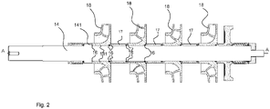
- FIG. 2 it is presented an embodiment of an impeller/ shaft assembly for a multistage centrifugal pump, such as presented in Fig. 1 .
- the impeller / shaft assembly comprises
- the impellers 18 there is provided a bush ring or bush rings 17.
- Bush rings may be used for bearing attachment or just as spacers between impellers.
- the impellers 18 and bush rings 17 form an axial array of tubular elements set on the shaft 14.
- the left end of the shaft 14 comprises a shaft collar 141 that forms an axial direction bracket for the array of impellers 18 and bush rings 17 to be tightened towards. This array is tightened from the right end of the shaft 14 with a tightening element, for example with a nut (not presented in the Fig. 2 ).
- the shaft 14 has a constant diameter at the length wherein the impellers 18 are configured to be assembled.
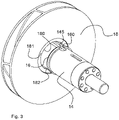
- FIG. 3 it is presented an embodiment of an impeller 18 / shaft 14 assembly for a multistage centrifugal pump.
- the Fig. 3 illustrates that the shaft 14 has a diameter that is smaller than the inner diameter of the hub 181 and adaptor ring 16 would be arranged into the axial opening 180 of the hub 181 to transmit the radial forces between the impeller 18 and the shaft 14.
- the hub 181 is provided with a circumferential cavity 182 or cavities 182 for the adaptor ring(s) 16 to fit in.
- the cavity 182 comprises radially inner surface which is parallel to the outer surface of the shaft 14 and the adaptor ring 16 has rectangular cross section.
- the torque (generated by a pump motor not shown in figures) is configured to be transmitted between the impeller 18 and the shaft 14 by a cotter joint 145.
- the adaptor ring 16 is a continuous ring or the adaptor ring 16 has a cut-out to form a C-shaped adaptor ring 16 to provide a passage for a cotter or key (not shown) between the hub 181 and the shaft 14. It depends for example on the cotter joint design which of the two options is more preferred for the adaptor ring 16 design, continuous ring or with a cut-out.
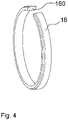
- Fig. 4 it is presented an embodiment of an adaptor ring 16.
- the function of the adaptor ring is to bear radial direction or compression forces between the impeller 18 and the shaft 14.
- the adaptor ring 16 has a cut-out 160 to form a C-shaped adaptor ring 16 to provide a passage for a cotter.
- the adaptor ring is made such material that is suitable for that kind of load, preferably it is made of composite material, steel or other metallic material.
- the adaptor ring 16 has a rectangular cross section so that it does not transfer any axial loads to radial loads or vice versa.
- the axial length of the adaptor ring is in a range 1/5 - 1/20 of the axial length of the hub 181, depending on the required strength dimensioning, material parameters, required load bearing capacity, etc..
Landscapes
- Engineering & Computer Science (AREA)
- Mechanical Engineering (AREA)
- General Engineering & Computer Science (AREA)
- Structures Of Non-Positive Displacement Pumps (AREA)
Abstract
Invention relates to a multistage centrifugal pump (10) for pumping fluid, the pump (10) comprising:
- a pump housing (11) having a fluid inlet (12) and a fluid outlet (13) and a flow channel (110) between the inlet (12) and the outlet (13) in the housing, the pump housing (11) is comprising a number of pumping stages,
- a shaft (14) mounted by bearings (15) for rotation about its center axis (A-A),
- a number of impellers (18), comprising a hub (181) having an axial opening (180) configured to be fitted on the shaft (14),
- when in use, power is transmitted though the rotating shaft 14 to the impellers (18), causing torque, radial forces and axial forces,
- over the length of the shaft (14) where the impellers (18) are configured to be assembled, the shaft (14) has a diameter that is smaller than the inner diameter of the hub (181) and an adaptor ring (16) is arranged into the axial opening (180) of the hub (181) to transmit the radial forces between the impeller (18) and the shaft (14).
- a pump housing (11) having a fluid inlet (12) and a fluid outlet (13) and a flow channel (110) between the inlet (12) and the outlet (13) in the housing, the pump housing (11) is comprising a number of pumping stages,
- a shaft (14) mounted by bearings (15) for rotation about its center axis (A-A),
- a number of impellers (18), comprising a hub (181) having an axial opening (180) configured to be fitted on the shaft (14),
- when in use, power is transmitted though the rotating shaft 14 to the impellers (18), causing torque, radial forces and axial forces,
- over the length of the shaft (14) where the impellers (18) are configured to be assembled, the shaft (14) has a diameter that is smaller than the inner diameter of the hub (181) and an adaptor ring (16) is arranged into the axial opening (180) of the hub (181) to transmit the radial forces between the impeller (18) and the shaft (14).
The invention relates also to a corresponding impeller shaft assembly and a method for manufacturing such.
Description
- The present invention relates to multistage centrifugal pump according to the preamble of claim 1. The present invention relates also to an impeller /shaft assembly for a multistage centrifugal pump according to the preamble of
claim 12. Furthermore the present invention relates also to a method for assembling an impeller / shaft assembly for a multistage centrifugal pump. - More specifically, the present invention relates to a multistage centrifugal pump for pumping fluid, the pump comprising:
- a pump housing having a fluid inlet and a fluid outlet and a flow channel between the inlet and the outlet in the housing, the pump housing is comprising a number of pumping stages,
- a shaft (14) mounted by bearings for rotation about its center axis,
- a number of impellers, the number of impellers is corresponding to the number of pumping stages, the impellers are rotatable by the shaft and arranged to be rotated about the axis in the flow channel, and each impeller comprises a hub having an axial opening configured to be fitted on the shaft and defining the length of the impeller in the axial direction,
- when in use, power is transmitted though the rotating shaft to the impellers, causing torque, radial forces and axial forces.
- Also more specifically, the present invention relates to an impeller /shaft assembly for a multistage centrifugal pump comprising
- a shaft for rotation about its center axis,
- a number of impellers, the impellers being fastened to the shaft, arranged to be rotated about the axis and each impeller comprises a hub to be fitted on the shaft and defining the length of the impeller in the axial direction.
- A multistage centrifugal pump has been disclosed for example in a patent document
GB1364117 - (a) a divided pump housing having an elongated pump chamber defined therein;
- (b) a pump impeller assembly having a plurality of impellers serially mounted on a rotatable shaft, said pump impeller assembly being mounted within said pump chamber. Divider retainer rings are mounted about the shaft and within all the impellers to retain such impellers in longitudinal position on the shaft. Keys are mounted in accommodating slots formed in and between the shaft and the impellers to retain such impellers in arcuate position on the shaft.
- An object of the invention is to provide a multistage centrifugal pump that is easy to assembly and where the assembled impeller/shaft combination can be balanced against vibrations in an efficient way. The same object also concerns service / maintenance operations, where the time and cost savings are an object. It is also an object of the invention to reduce the manufacturing cost of the multistage pump components. Thus the object is to provide a multistage centrifugal pump in which the operational and manufacturing relating performance is improved compared to the prior art solutions.
- Objects of the invention can be met substantially as is disclosed in the independent claims and in the other claims describing more details of different embodiments of the invention.
- According to an embodiment of the invention it is provided a multistage centrifugal pump for pumping fluid, the pump comprising:
- a pump housing having a fluid inlet and a fluid outlet and a flow channel between the inlet and the outlet in the housing, the pump housing is comprising a number of pumping stages,
- a shaft mounted by bearings for rotation about its center axis,
- a number of impellers, the number of impellers is corresponding to the number of pumping stages, the impellers are rotatable by the shaft and arranged to be rotated about the axis in the flow channel, and each impeller comprises a hub having an axial opening configured to be fitted on the shaft and defining the length of the impeller in the axial direction,
- when in use, power is transmitted though the rotating shaft to the impellers, causing torque, radial forces and axial forces,
wherein over the length of the shaft where the impellers are configured to be assembled, the shaft has a diameter that is smaller than the inner diameter of the hub and an adaptor ring is arranged into the axial opening of the hub to transmit the radial forces between the impeller and the shaft. This provides a multistage centrifugal pump for pumping fluid which pump's performance is considerably improved. - According to an embodiment of the invention the hub is connected to the shaft by two adaptor rings. The hub is generally a cylindrical / tubular element and the two adaptor rings are preferably placed to ends of the hub so that the supporting effect in the radial direction is at the top level. If the adaptor rings would be set at a narrower distance in relation to each other, it might cause kind of wobbling effect to the impeller. The hub is configured to be tighten in radial direction to the shaft by two adaptor rings, each of the adaptor rings extending from an axial end of the hub towards an axial centre of the hub. Alternatively according to another embodiment, there is one adaptor ring in one end and the other end of the hub is connected to the following hub, bush ring or corresponding with an interlocking shape. By this embodiment the hubs form an array of hubs or bush rings each having only one adaptor ring for connecting to the shaft.
- According to an embodiment the hub is provided with a circumferential cavity or cavities for the adaptor ring(s) to fit in. The length of said cavity is preferably slightly longer than the width of the adaptor ring so that the adaptor ring stays within the hub, meaning not protruding out from the cavity. This prevents the axial load to be delivered through the adaptor rings. The axial forces are configured to be transmitted though the hub to the next hub, a bush ring or a shaft collar receiving the axial load. Thus, the axial loads are configured to be delivered through of the hub ends, not through the adaptor rings. So principally it could be said that the adaptor ring is floating on the shaft but since it has tight connection in the radial direction, it does not actually float but has an undefined axial connection to the shaft. This has the effect that the loads in different directions between the shaft and impeller can be separated to different elements. Preferably the shaft has a constant diameter at the length wherein the impellers are configured to be assembled and therefore the shaft can be made as a single diameter smooth surfaced shaft at the location for impellers. This enables the shaft to be manufactured efficiently to an even strength and the assembly of parts, impellers, bush rings and adaptor rings to be simple and quick operation.
- According to an embodiment of the invention the torque is configured to be transmitted between the impeller and the shaft by a cotter joint. This is a simple and reliable coupling for delivering torque between the shaft and the impeller. Depending on this coupling type, the adaptor ring is a continuous ring or the adaptor ring has a cut-out to form a C-shaped adaptor ring to provide a passage for a cotter between the hub and the shaft. An adaptor ring having a C-shape can be installed quickly since temperatures of the parts are not especially critical for assembly. A continuous ring having tight tolerances need to be precisely on a designed temperature for the assembly, otherwise the parts may not fit.
- According to an embodiment of the invention it is provided a impeller / shaft assembly for a multistage centrifugal pump comprising
- a shaft for rotation about its center axis,
- a number of impellers, the impellers being fastened to the shaft, arranged to be rotated about the axis and each impeller comprises a hub to be fitted on the shaft and defining the length of the impeller in the axial direction,
- over the length of the shaft where the impellers are configured to be assembled, the shaft has a diameter that is smaller than the inner diameter of the hub, the impeller and the shaft are fastened to each other via adaptor rings. This impeller / shaft assembly can be assembled and balanced at workshop and then delivered to the client as a spare part.
- According to an embodiment a method for assembling an impeller / shaft assembly for a multistage centrifugal pump, the method comprising following steps:
- a) providing a shaft at a predetermined temperature and attaching it to an assembly jig so that the larger diameter end of the shaft is attached to the jig,
- b) providing a number of adaptor rings warmed to a temperature higher than the shaft temperature,
- c) sliding a first adaptor ring to its position towards a shaft collar,
- d) assembling the impeller on the shaft so that the hub is moved axially in respect to the adaptor ring such that the hub encloses radially the adaptor ring and slides to its final position so that the hub cooperates with the first adaptor ring provided on the shaft so as to radially support the hub,
- e) sliding a second adaptor ring to its position so that the hub cooperates with the second adaptor so as to radially support the hub
- f) repeating the steps c) to e) until all the impellers are assembled on their positions,
- tightening a fastening element holding the impellers in their axial position. This method enables a fast and accurate assembly of parts to for the impeller / shaft assembly. Conventionally the shaft has been machined with multiple diameters and grooves for retainer rings and like, and the assembly has been really demanding operation where the parts have been heated to different temperatures and then quickly put together. Now the current method and design enables less complicated assembly with very accurate end results relating to the achieved balancing rate and positioning accuracy.
- The exemplary embodiments of the invention presented in this patent application are not to be interpreted to pose limitations to the applicability of the appended claims. The verb "to comprise" is used in this patent application as an open limitation that does not exclude the existence of also unrecited features. The features recited in depending claims are mutually freely combinable unless otherwise explicitly stated. The novel features which are considered as characteristic of the invention are set forth in particular in the appended claims.
- In the following, the invention will be described with reference to the accompanying exemplary, schematic drawings, in which
-
Figure 1 illustrates a multistage centrifugal pump for pumping fluid according to an embodiment of the invention, -
Figure 2 illustrates an impeller /shaft assembly for a multistage centrifugal pump according to another embodiment of the invention, -
Figure 3 illustrates an impeller /shaft assembly for a multistage centrifugal pump according to still another embodiment of the invention, -
Figure 4 illustrates an adaptor ring for a multistage centrifugal pump for pumping fluid according to an embodiment of the invention. -
Figure 1 depicts schematically a multistagecentrifugal pump 10 for pumping fluid, thepump 10 comprising: - a
pump housing 11 having afluid inlet 12 and afluid outlet 13 and aflow channel 110 between theinlet 12 and theoutlet 13 in the housing, thepump housing 11 is comprising a number of pumping stages, - a
shaft 14 mounted bybearings 15 for rotation about its center axis A-A, - a number of
impellers 18, the number ofimpellers 18 is corresponding to the number of pumping stages, theimpellers 18 are rotatable by theshaft 14 and arranged to be rotated about the axis A-A in theflow channel 110, and eachimpeller 18 comprises ahub 181 having an axial opening configured to be fitted on theshaft 14 and defining the length of theimpeller 18 in the axial direction, - when in use, power is transmitted though the rotating
shaft 14 to theimpellers 18, causing torque, radial forces and axial forces, - over the length of the
shaft 14 where theimpellers 18 are configured to be assembled, theshaft 14 has a diameter that is smaller than the inner diameter of thehub 181 and anadaptor ring 16 is arranged into the axial opening of thehub 181 to transmit the radial forces between theimpeller 18 and theshaft 14. - In
Fig. 2 it is presented an embodiment of an impeller/ shaft assembly for a multistage centrifugal pump, such as presented inFig. 1 . The impeller / shaft assembly comprises - a
shaft 14 for rotation about its center axis A-A, - a number of
impellers 18, theimpellers 18 being fastened to theshaft 14, arranged to be rotated about the axis A-A and eachimpeller 18 comprises ahub 181 to be fitted on theshaft 14 and defining the length of theimpeller 18 in the axial direction, - over the length of the
shaft 14 where theimpellers 18 are configured to be assembled, theshaft 14 has a diameter that is smaller than the inner diameter of thehub 181, theimpeller 18 and theshaft 14 are fastened to each other via adaptor rings 17. Thehub 181 is configured to be tighten in radial direction to theshaft 14 by two adaptor rings 16, each of the adaptor rings 16 extending from an axial end of the hub towards an axial centre of the hub, oneadaptor ring 16 at each end of thehub 181 in length at axial direction. Another embodiment is to have oneadaptor ring 16 for eachhub 181 but connect thehub 181 to the followinghub 181 with an interlocking shape such as a tongue / groove combination or alike. This embodiment is not shown in the figures. - Between the
impellers 18 there is provided a bush ring or bush rings 17. Bush rings may be used for bearing attachment or just as spacers between impellers. In combination, theimpellers 18 and bush rings 17 form an axial array of tubular elements set on theshaft 14. In the embodiment of theFig 2 , the left end of theshaft 14 comprises ashaft collar 141 that forms an axial direction bracket for the array ofimpellers 18 and bush rings 17 to be tightened towards. This array is tightened from the right end of theshaft 14 with a tightening element, for example with a nut (not presented in theFig. 2 ). - According to an embodiment of the invention the
shaft 14 has a constant diameter at the length wherein theimpellers 18 are configured to be assembled. This enables and is especially suitable for above explained multi stage centrifugal pump, an embodiment of method for assembling an impeller / shaft assembly for a multistage centrifugal pump, the method comprising following steps: - a) providing a
shaft 14 at a predetermined temperature and attaching it to an assembly jig so that the larger diameter end of the shaft is attached to the jig, - b) providing a number of adaptor rings 16 warmed to a temperature higher than the
shaft 14 temperature, - c) sliding a
first adaptor ring 16 to its position towards a shaft collar141, - d) assembling the
impeller 18 on theshaft 14 so that thehub 181 is moved axially in respect to theadaptor ring 16 such that thehub 181 encloses radially theadaptor ring 16 and slides to its final position so that thehub 181 cooperates with thefirst adaptor ring 16 provided on theshaft 14 so as to radially support thehub 181, - e) sliding a
second adaptor ring 16 to its position so that thehub 181 cooperates with thesecond adaptor ring 16 so as to radially support thehub 181, - f) repeating the steps c) to e) until all the impellers are assembled on their positions,
- tightening a fastening element holding the impellers in their axial position. The method may further comprise the following step (if the construction requires):
- e0) sliding a
bush ring 17 on theshaft 14 for providing a spacing between theimpellers 18. In the present method the temperature differences required for assembly are significantly less than with conventional constructions. As the impellers are quite often large and heavy parts, handling of such parts is complicated if the assembly temperature needs to be elevated to high temperatures to utilize the thermal expansion of the parts. In a case of conventional construction where the radial fit is done by machining the impeller hub tolerance to fit snugly on the shaft, the temperature difference between the shaft and the impeller needs to be considerable. The impeller is normally heated and the shaft may be cooled. If the temperature difference is lost during the assembly for some reason, there is a risk that the impeller gets stuck to an incorrect position on the shaft. Also in the conventional construction there are retainer rings to keep the axial positions correct, bearings and like, it takes some time to assembly and fit the parts together. These constructional elements that slow down the assembly, they also increase the risk of foresaid loss of the temperature difference during the assembly. The removal of such situation may even deteriorate the surfaces of the shaft and surfaces of an axial opening inside the hub. With the present method just the adaptor rings need to be heated, but the impeller does not need to be heated, because the snug fit is achieved by the tolerances of theadaptor ring 16 /shaft 14 andadaptor ring 16 /hub cavity 182. And if the adaptor ring has a cut-out to form a C-shaped adaptor ring it is used, the need for heating is minimal or not even needed. - In
Fig. 3 it is presented an embodiment of animpeller 18 /shaft 14 assembly for a multistage centrifugal pump. TheFig. 3 illustrates that theshaft 14 has a diameter that is smaller than the inner diameter of thehub 181 andadaptor ring 16 would be arranged into theaxial opening 180 of thehub 181 to transmit the radial forces between theimpeller 18 and theshaft 14. Thehub 181 is provided with acircumferential cavity 182 orcavities 182 for the adaptor ring(s) 16 to fit in. Thecavity 182 comprises radially inner surface which is parallel to the outer surface of theshaft 14 and theadaptor ring 16 has rectangular cross section. The torque (generated by a pump motor not shown in figures) is configured to be transmitted between theimpeller 18 and theshaft 14 by a cotter joint 145. Theadaptor ring 16 is a continuous ring or theadaptor ring 16 has a cut-out to form a C-shapedadaptor ring 16 to provide a passage for a cotter or key (not shown) between thehub 181 and theshaft 14. It depends for example on the cotter joint design which of the two options is more preferred for theadaptor ring 16 design, continuous ring or with a cut-out. - In
Fig. 4 it is presented an embodiment of anadaptor ring 16. The function of the adaptor ring is to bear radial direction or compression forces between theimpeller 18 and theshaft 14. Theadaptor ring 16 has a cut-out 160 to form a C-shapedadaptor ring 16 to provide a passage for a cotter. The adaptor ring is made such material that is suitable for that kind of load, preferably it is made of composite material, steel or other metallic material. Preferably theadaptor ring 16 has a rectangular cross section so that it does not transfer any axial loads to radial loads or vice versa. The axial length of the adaptor ring is in a range 1/5 - 1/20 of the axial length of thehub 181, depending on the required strength dimensioning, material parameters, required load bearing capacity, etc.. - While the invention has been described herein by way of examples in connection with what are, at present, considered to be the most preferred embodiments, it is to be understood that the invention is not limited to the disclosed embodiments, but is intended to cover various combinations or modifications of its features, and several other applications included within the scope of the invention, as defined in the appended claims. The details mentioned in connection with any embodiment above may be used in connection with another embodiment when such combination is technically feasible.
-
- 10
- multistage centrifugal pump
- 11
- pump housing
- 110
- flow channel
- 12
- inlet
- 13
- outlet
- 14
- shaft
- 140
- shaft surface
- 141
- shaft collar
- 145
- cotter joint
- 15
- bearing
- 16
- adaptor ring
- 160
- adaptor ring cut-out
- 17
- bush ring
- 18
- impeller
- 180
- axial opening
- 181
- hub
- 182
- cavity
- A-A
- center axis
Claims (15)
- A multistage centrifugal pump (10) for pumping fluid, the pump (10) comprising:- a pump housing (11) having a fluid inlet (12) and a fluid outlet (13) and a flow channel (110) between the inlet (12) and the outlet (13) in the housing, the pump housing (11) is comprising a number of pumping stages,- a shaft (14) mounted by bearings (15) for rotation about its center axis (A-A),- a number of impellers (18), the number of impellers (18) is corresponding to the number of pumping stages, the impellers (18) are rotatable by the shaft (14) and arranged to be rotated about the axis (A-A) in the flow channel (110), and each impeller (18) comprises a hub (181) having an axial opening (180) configured to be fitted on the shaft (14) and defining the length of the impeller (18) in the axial direction,- when in use, power is transmitted though the rotating shaft (14) to the impellers (18), causing torque, radial forces and axial forces,
characterized in that, over the length of the shaft (14) where the impellers (18) are configured to be assembled, the shaft (14) has a diameter that is smaller than the inner diameter of the hub (181) and an adaptor ring (16) is arranged into the axial opening (180) of the hub (181) to transmit the radial forces between the impeller (18) and the shaft (14). - A multistage centrifugal pump (10) according to claim 1, characterized in that the hub (181) is connected to the shaft (14) by one or two adaptor rings (16).
- A multistage centrifugal pump (10) according to claim 1, characterized in that that the axial forces are configured to be transmitted though the hub (181) to the next hub (181), a bush ring (17) or a shaft collar (141) receiving the axial load.
- A multistage centrifugal pump (10) according to claim 1 or 2, characterized in that that the torque is configured to be transmitted between the impeller (18) and the shaft (14) by a cotter joint (145).
- A multistage centrifugal pump (10) according to any of the preceding claims, characterized in that that the hub (181) is configured to be tighten in radial direction to the shaft (14) by two adaptor rings (16), each of the adaptor rings (16) extending from an axial end of the hub (181) towards an axial centre of the hub (181).
- A multistage centrifugal pump (10) according to any of the preceding claims, characterized in that that the hub (181) is provided with a circumferential cavity (182) or cavities (182) for the adaptor ring(s) (16) to fit in.
- A multistage centrifugal pump (10) according to any of the preceding claims, characterized in that that the shaft (14) has a constant diameter at the length wherein the impellers (18) are configured to be assembled.
- A multistage centrifugal pump (10) according to any of the preceding claims, characterized in that that the adaptor ring (16) is a continuous ring or the adaptor ring (16) has a cut-out to form a C-shaped adaptor ring (16) to provide a passage for a cotter between the hub (181) and the shaft (14).
- A multistage centrifugal pump (10) according to any of the preceding claims, characterized in that that the adaptor ring (16) is of composite material, steel or other metallic material.
- A multistage centrifugal pump (10) according to any of the preceding claims, characterized in that that the cavity (182) comprises radially inner surface which is parallel to the outer surface of the shaft (14) and the adaptor ring (16) has rectangular cross section.
- A multistage centrifugal pump (10) according to any of the preceding claims, characterized in that that the axial length of the adaptor ring (16) is 1/5 - 1/20 of the axial length of the hub (181).
- An impeller (18) / shaft (14) assembly for a multistage centrifugal pump (10) comprising- a shaft (14) for rotation about its center axis (A-A),- a number of impellers (18), the impellers (18) being fastened to the shaft (14), arranged to be rotated about the axis (A-A) and each impeller (18) comprises a hub (181) to be fitted on the shaft (18) and defining the length of the impeller (18) in the axial direction,
characterized in that, over the length of the shaft (14) where the impellers (18) are configured to be assembled, the shaft (14) has a diameter that is smaller than the inner diameter of the hub (181), the impeller (18) and the shaft (14) are fastened to each other via adaptor rings (16). - An impeller (18) / shaft (14) assembly for a multistage centrifugal pump (10) according to any of the preceding claims, characterized in that that the hub (181) is configured to be tighten in radial direction to the shaft (14) by two adaptor rings (16), one adaptor ring (16) at each end of the hub (181) in length at axial direction.
- A method for assembling an impeller (18) / shaft (14) assembly for a multistage centrifugal pump (10), the method comprising following steps:- a) providing a shaft (14) at a predetermined temperature and attaching it to an assembly jig so that the larger diameter end of the shaft (14) is attached to the jig,- b) providing a number of adaptor rings (16) warmed to a temperature higher than the shaft (14) temperature,- c) sliding a first adaptor ring (16) to its position towards a shaft collar (141),- d) assembling the impeller (18) on the shaft (14) so that the hub (181) is moved axially in respect to the adaptor ring (16) such that the hub (181) encloses radially the adaptor ring (16) and slides to its final position so that the hub (181) cooperates with the first adaptor ring (16) provided on the shaft (14) so as to radially support the hub (181),- e) sliding a second adaptor ring (16) to its position so that the hub (181) cooperates with the second adaptor ring (16) so as to radially support the hub (181),- f) repeating the steps c) to e) until all the impellers (18) are assembled on their positions,- tightening a fastening element holding the impellers (18) in their axial position.
- A method for assembling an impeller (18) / shaft (14) assembly for a multistage centrifugal pump (10) according to claim 14, the method further comprising the following step:- e0) sliding a bush ring (17) on the shaft (14) for providing a spacing between the impellers (18).
Priority Applications (6)
| Application Number | Priority Date | Filing Date | Title |
|---|---|---|---|
| EP21154000.0A EP4036420A1 (en) | 2021-01-28 | 2021-01-28 | A multistage centrifugal pump for pumping fluid, an impeller / shaft assembly and a method for assembling an impeller / shaft |
| US18/272,668 US12480494B2 (en) | 2021-01-28 | 2022-01-24 | Multistage centrifugal pump for pumping fluid, an impeller/ shaft assembly and a method for assembling an impeller/ shaft assembly |
| CN202280010626.3A CN116724175A (en) | 2021-01-28 | 2022-01-24 | Multistage centrifugal pump for pumping fluids, impeller/shaft assembly and method for assembling impeller/shaft assembly |
| PCT/EP2022/051463 WO2022161905A1 (en) | 2021-01-28 | 2022-01-24 | A multistage centrifugal pump for pumping fluid, an impeller / shaft assembly and a method for assembling an impeller / shaft assembly |
| EP22701602.9A EP4285032B1 (en) | 2021-01-28 | 2022-01-24 | A multistage centrifugal pump for pumping fluid, an impeller / shaft assembly and a method for assembling an impeller / shaft assembly |
| FIEP22701602.9T FI4285032T3 (en) | 2021-01-28 | 2022-01-24 | A multistage centrifugal pump for pumping fluid, an impeller / shaft assembly and a method for assembling an impeller / shaft assembly |
Applications Claiming Priority (1)
| Application Number | Priority Date | Filing Date | Title |
|---|---|---|---|
| EP21154000.0A EP4036420A1 (en) | 2021-01-28 | 2021-01-28 | A multistage centrifugal pump for pumping fluid, an impeller / shaft assembly and a method for assembling an impeller / shaft |
Publications (1)
| Publication Number | Publication Date |
|---|---|
| EP4036420A1 true EP4036420A1 (en) | 2022-08-03 |
Family
ID=74346961
Family Applications (2)
| Application Number | Title | Priority Date | Filing Date |
|---|---|---|---|
| EP21154000.0A Withdrawn EP4036420A1 (en) | 2021-01-28 | 2021-01-28 | A multistage centrifugal pump for pumping fluid, an impeller / shaft assembly and a method for assembling an impeller / shaft |
| EP22701602.9A Active EP4285032B1 (en) | 2021-01-28 | 2022-01-24 | A multistage centrifugal pump for pumping fluid, an impeller / shaft assembly and a method for assembling an impeller / shaft assembly |
Family Applications After (1)
| Application Number | Title | Priority Date | Filing Date |
|---|---|---|---|
| EP22701602.9A Active EP4285032B1 (en) | 2021-01-28 | 2022-01-24 | A multistage centrifugal pump for pumping fluid, an impeller / shaft assembly and a method for assembling an impeller / shaft assembly |
Country Status (5)
| Country | Link |
|---|---|
| US (1) | US12480494B2 (en) |
| EP (2) | EP4036420A1 (en) |
| CN (1) | CN116724175A (en) |
| FI (1) | FI4285032T3 (en) |
| WO (1) | WO2022161905A1 (en) |
Citations (7)
| Publication number | Priority date | Publication date | Assignee | Title |
|---|---|---|---|---|
| US1448925A (en) * | 1922-03-29 | 1923-03-20 | Ingersoll Rand Co | Impeller mounting for centrifugal pumps |
| GB1364117A (en) | 1970-12-21 | 1974-08-21 | Borg Warner | Multistage centrifugal pumps |
| CN203189272U (en) * | 2013-03-14 | 2013-09-11 | 山东硕博泵业有限公司 | Double-hulled and multistage horizontal split centrifugal pump |
| CN205331041U (en) * | 2015-12-22 | 2016-06-22 | 山东长志泵业有限公司 | Easy dismouting axial dissection multistage centrifugal pump impeller positioner |
| CN206681995U (en) * | 2017-04-07 | 2017-11-28 | 石家庄强大泵业集团有限责任公司 | Two-stage Double absorption midle-opening centrifugal pump |
| CN207049061U (en) * | 2017-04-07 | 2018-02-27 | 兰州兰泵有限公司 | A kind of impeller linking structure of centrifugal multistage pump multiple centrifugal pump |
| CN111828372A (en) * | 2020-06-23 | 2020-10-27 | 北京航天动力研究所 | Flexible rotor of ultrahigh-rotating-speed liquid hydrogen turbopump |
Family Cites Families (10)
| Publication number | Priority date | Publication date | Assignee | Title |
|---|---|---|---|---|
| US5722812A (en) * | 1996-06-20 | 1998-03-03 | Baker Hughes Incorporated | Abrasion resistant centrifugal pump |
| EP2256347A1 (en) * | 2009-05-26 | 2010-12-01 | Siemens Aktiengesellschaft | Rotating machine and method of assembly thereof |
| US8616863B2 (en) * | 2011-03-29 | 2013-12-31 | Baker Hughes Incorporated | ESP with offset laterally loaded bearings |
| US10267315B2 (en) * | 2013-11-28 | 2019-04-23 | Acd, Llc | Cryogenic submerged pump for LNG, light hydrocarbon and other electrically non-conducting and non-corrosive fluids |
| US9845808B2 (en) * | 2013-12-10 | 2017-12-19 | Baker Hughes, A Ge Company, Llc | Spherical sleeve and bushing bearing for centrifugal pump stage |
| US9816519B2 (en) * | 2015-12-03 | 2017-11-14 | Summit Esp, Llc | Press-fit bearing locking system, apparatus and method |
| DE102016111406A1 (en) * | 2016-06-22 | 2017-12-28 | Xylem Ip Management Sàrl | Kit for a pumping device |
| PL3516238T3 (en) * | 2016-09-26 | 2021-12-06 | Fluid Handling Llc. | Multi-stage impeller produced via additive manufacturing |
| CN207750243U (en) * | 2017-12-08 | 2018-08-21 | 常州市洛锐电器有限公司 | A kind of centrifugal multistage pump multiple centrifugal pump |
| EP3686436A1 (en) * | 2019-07-31 | 2020-07-29 | Sulzer Management AG | Multistage pump and subsea pumping arrangement |
-
2021
- 2021-01-28 EP EP21154000.0A patent/EP4036420A1/en not_active Withdrawn
-
2022
- 2022-01-24 FI FIEP22701602.9T patent/FI4285032T3/en active
- 2022-01-24 US US18/272,668 patent/US12480494B2/en active Active
- 2022-01-24 WO PCT/EP2022/051463 patent/WO2022161905A1/en not_active Ceased
- 2022-01-24 EP EP22701602.9A patent/EP4285032B1/en active Active
- 2022-01-24 CN CN202280010626.3A patent/CN116724175A/en active Pending
Patent Citations (7)
| Publication number | Priority date | Publication date | Assignee | Title |
|---|---|---|---|---|
| US1448925A (en) * | 1922-03-29 | 1923-03-20 | Ingersoll Rand Co | Impeller mounting for centrifugal pumps |
| GB1364117A (en) | 1970-12-21 | 1974-08-21 | Borg Warner | Multistage centrifugal pumps |
| CN203189272U (en) * | 2013-03-14 | 2013-09-11 | 山东硕博泵业有限公司 | Double-hulled and multistage horizontal split centrifugal pump |
| CN205331041U (en) * | 2015-12-22 | 2016-06-22 | 山东长志泵业有限公司 | Easy dismouting axial dissection multistage centrifugal pump impeller positioner |
| CN206681995U (en) * | 2017-04-07 | 2017-11-28 | 石家庄强大泵业集团有限责任公司 | Two-stage Double absorption midle-opening centrifugal pump |
| CN207049061U (en) * | 2017-04-07 | 2018-02-27 | 兰州兰泵有限公司 | A kind of impeller linking structure of centrifugal multistage pump multiple centrifugal pump |
| CN111828372A (en) * | 2020-06-23 | 2020-10-27 | 北京航天动力研究所 | Flexible rotor of ultrahigh-rotating-speed liquid hydrogen turbopump |
Also Published As
| Publication number | Publication date |
|---|---|
| FI4285032T3 (en) | 2025-05-21 |
| CN116724175A (en) | 2023-09-08 |
| US20250075702A1 (en) | 2025-03-06 |
| EP4285032A1 (en) | 2023-12-06 |
| US12480494B2 (en) | 2025-11-25 |
| WO2022161905A1 (en) | 2022-08-04 |
| EP4285032B1 (en) | 2025-03-05 |
Similar Documents
| Publication | Publication Date | Title |
|---|---|---|
| EP1451472B1 (en) | Improved thrust bearing for multistage centrifugal pumps | |
| EP2031251B1 (en) | Multi-ribbed keyless coupling | |
| EP3001037B1 (en) | Electric fluid pump with improved rotor unit and method of construction thereof | |
| EP1980721B2 (en) | Variable stator vane assembly for a turbine engine | |
| US10794390B2 (en) | Modular turbo compressor shaft | |
| US5344285A (en) | Centrifugal pump with monolithic diffuser and return vane channel ring member | |
| US3861825A (en) | Multistage pump and manufacturing method | |
| US7086830B2 (en) | Tube-type vortex reducer with retaining ring | |
| EP2872744B1 (en) | A rotor for a radial compressor and a method for construction thereof | |
| CA2874009C (en) | Spherical sleeve and bushing bearing for centrifugal pump stage | |
| EP3592982B1 (en) | A bearing arrangement for a drive shaft of a turbo-machine, and a turbo-machine including such a bearing arrangement | |
| CN105952752A (en) | Metallic insert with smooth contours for use with composite working members | |
| EP4285032B1 (en) | A multistage centrifugal pump for pumping fluid, an impeller / shaft assembly and a method for assembling an impeller / shaft assembly | |
| US11346364B2 (en) | Multistage centrifugal fluid machine | |
| US20130089432A1 (en) | Shaft assembly for a gas turbine engine | |
| US6540474B2 (en) | Side-channel pump | |
| US10494937B2 (en) | Inner ring for an annular guide vane assembly of a turbomachine | |
| EP1106780B1 (en) | Turbine rotor torque transmission | |
| EP1050665A2 (en) | Bushing retention system for cooling tubes in a gas turbine rotor | |
| WO2015163999A1 (en) | Universal housing for a centrifugal gas compressor | |
| CN101832272B (en) | Multi-stage centrifugal pump assembly | |
| EP3364036A1 (en) | Axially split bearing housing and a rotary machine | |
| WO2018162660A1 (en) | A double-stage impeller arrangement for a double-stage centrifugal turbo-compressor | |
| EP4038281B1 (en) | Bush retention system | |
| US11773702B2 (en) | Motor bearing with anti-rotation spring for electrical submersible well pump |
Legal Events
| Date | Code | Title | Description |
|---|---|---|---|
| PUAI | Public reference made under article 153(3) epc to a published international application that has entered the european phase |
Free format text: ORIGINAL CODE: 0009012 |
|
| STAA | Information on the status of an ep patent application or granted ep patent |
Free format text: STATUS: THE APPLICATION HAS BEEN PUBLISHED |
|
| AK | Designated contracting states |
Kind code of ref document: A1 Designated state(s): AL AT BE BG CH CY CZ DE DK EE ES FI FR GB GR HR HU IE IS IT LI LT LU LV MC MK MT NL NO PL PT RO RS SE SI SK SM TR |
|
| STAA | Information on the status of an ep patent application or granted ep patent |
Free format text: STATUS: THE APPLICATION IS DEEMED TO BE WITHDRAWN |
|
| 18D | Application deemed to be withdrawn |
Effective date: 20230204 |