EP4036358A1 - Sliding door position adjustment assisting device and sliding door position adjustment assisting system - Google Patents
Sliding door position adjustment assisting device and sliding door position adjustment assisting system Download PDFInfo
- Publication number
- EP4036358A1 EP4036358A1 EP22154333.3A EP22154333A EP4036358A1 EP 4036358 A1 EP4036358 A1 EP 4036358A1 EP 22154333 A EP22154333 A EP 22154333A EP 4036358 A1 EP4036358 A1 EP 4036358A1
- Authority
- EP
- European Patent Office
- Prior art keywords
- sliding door
- measurement value
- door
- position adjustment
- unit
- Prior art date
- Legal status (The legal status is an assumption and is not a legal conclusion. Google has not performed a legal analysis and makes no representation as to the accuracy of the status listed.)
- Withdrawn
Links
Images





Classifications
-
- E—FIXED CONSTRUCTIONS
- E05—LOCKS; KEYS; WINDOW OR DOOR FITTINGS; SAFES
- E05F—DEVICES FOR MOVING WINGS INTO OPEN OR CLOSED POSITION; CHECKS FOR WINGS; WING FITTINGS NOT OTHERWISE PROVIDED FOR, CONCERNED WITH THE FUNCTIONING OF THE WING
- E05F15/00—Power-operated mechanisms for wings
- E05F15/40—Safety devices, e.g. detection of obstructions or end positions
- E05F15/41—Detection by monitoring transmitted force or torque; Safety couplings with activation dependent upon torque or force, e.g. slip couplings
-
- E—FIXED CONSTRUCTIONS
- E05—LOCKS; KEYS; WINDOW OR DOOR FITTINGS; SAFES
- E05F—DEVICES FOR MOVING WINGS INTO OPEN OR CLOSED POSITION; CHECKS FOR WINGS; WING FITTINGS NOT OTHERWISE PROVIDED FOR, CONCERNED WITH THE FUNCTIONING OF THE WING
- E05F15/00—Power-operated mechanisms for wings
- E05F15/60—Power-operated mechanisms for wings using electrical actuators
- E05F15/603—Power-operated mechanisms for wings using electrical actuators using rotary electromotors
- E05F15/632—Power-operated mechanisms for wings using electrical actuators using rotary electromotors for horizontally-sliding wings
- E05F15/655—Power-operated mechanisms for wings using electrical actuators using rotary electromotors for horizontally-sliding wings specially adapted for vehicle wings
- E05F15/659—Control circuits therefor
-
- B—PERFORMING OPERATIONS; TRANSPORTING
- B61—RAILWAYS
- B61B—RAILWAY SYSTEMS; EQUIPMENT THEREFOR NOT OTHERWISE PROVIDED FOR
- B61B1/00—General arrangement of stations, platforms, or sidings; Railway networks; Rail vehicle marshalling systems
- B61B1/02—General arrangement of stations and platforms including protection devices for the passengers
-
- B—PERFORMING OPERATIONS; TRANSPORTING
- B61—RAILWAYS
- B61D—BODY DETAILS OR KINDS OF RAILWAY VEHICLES
- B61D19/00—Door arrangements specially adapted for rail vehicles
- B61D19/02—Door arrangements specially adapted for rail vehicles for carriages
- B61D19/026—Safety devices for preventing passengers from being injured by movements of doors or variations in air pressure
-
- E—FIXED CONSTRUCTIONS
- E05—LOCKS; KEYS; WINDOW OR DOOR FITTINGS; SAFES
- E05D—HINGES OR SUSPENSION DEVICES FOR DOORS, WINDOWS OR WINGS
- E05D13/00—Accessories for sliding or lifting wings, e.g. pulleys, safety catches
-
- E—FIXED CONSTRUCTIONS
- E05—LOCKS; KEYS; WINDOW OR DOOR FITTINGS; SAFES
- E05F—DEVICES FOR MOVING WINGS INTO OPEN OR CLOSED POSITION; CHECKS FOR WINGS; WING FITTINGS NOT OTHERWISE PROVIDED FOR, CONCERNED WITH THE FUNCTIONING OF THE WING
- E05F15/00—Power-operated mechanisms for wings
- E05F15/40—Safety devices, e.g. detection of obstructions or end positions
- E05F15/42—Detection using safety edges
-
- E—FIXED CONSTRUCTIONS
- E05—LOCKS; KEYS; WINDOW OR DOOR FITTINGS; SAFES
- E05F—DEVICES FOR MOVING WINGS INTO OPEN OR CLOSED POSITION; CHECKS FOR WINGS; WING FITTINGS NOT OTHERWISE PROVIDED FOR, CONCERNED WITH THE FUNCTIONING OF THE WING
- E05F15/00—Power-operated mechanisms for wings
- E05F15/60—Power-operated mechanisms for wings using electrical actuators
- E05F15/603—Power-operated mechanisms for wings using electrical actuators using rotary electromotors
- E05F15/632—Power-operated mechanisms for wings using electrical actuators using rotary electromotors for horizontally-sliding wings
-
- E—FIXED CONSTRUCTIONS
- E05—LOCKS; KEYS; WINDOW OR DOOR FITTINGS; SAFES
- E05F—DEVICES FOR MOVING WINGS INTO OPEN OR CLOSED POSITION; CHECKS FOR WINGS; WING FITTINGS NOT OTHERWISE PROVIDED FOR, CONCERNED WITH THE FUNCTIONING OF THE WING
- E05F15/00—Power-operated mechanisms for wings
- E05F15/60—Power-operated mechanisms for wings using electrical actuators
- E05F15/603—Power-operated mechanisms for wings using electrical actuators using rotary electromotors
- E05F15/632—Power-operated mechanisms for wings using electrical actuators using rotary electromotors for horizontally-sliding wings
- E05F15/635—Power-operated mechanisms for wings using electrical actuators using rotary electromotors for horizontally-sliding wings operated by push-pull mechanisms, e.g. flexible or rigid rack-and-pinion arrangements
-
- E—FIXED CONSTRUCTIONS
- E05—LOCKS; KEYS; WINDOW OR DOOR FITTINGS; SAFES
- E05F—DEVICES FOR MOVING WINGS INTO OPEN OR CLOSED POSITION; CHECKS FOR WINGS; WING FITTINGS NOT OTHERWISE PROVIDED FOR, CONCERNED WITH THE FUNCTIONING OF THE WING
- E05F15/00—Power-operated mechanisms for wings
- E05F15/60—Power-operated mechanisms for wings using electrical actuators
- E05F15/603—Power-operated mechanisms for wings using electrical actuators using rotary electromotors
- E05F15/632—Power-operated mechanisms for wings using electrical actuators using rotary electromotors for horizontally-sliding wings
- E05F15/655—Power-operated mechanisms for wings using electrical actuators using rotary electromotors for horizontally-sliding wings specially adapted for vehicle wings
-
- E—FIXED CONSTRUCTIONS
- E05—LOCKS; KEYS; WINDOW OR DOOR FITTINGS; SAFES
- E05Y—INDEXING SCHEME ASSOCIATED WITH SUBCLASSES E05D AND E05F, RELATING TO CONSTRUCTION ELEMENTS, ELECTRIC CONTROL, POWER SUPPLY, POWER SIGNAL OR TRANSMISSION, USER INTERFACES, MOUNTING OR COUPLING, DETAILS, ACCESSORIES, AUXILIARY OPERATIONS NOT OTHERWISE PROVIDED FOR, APPLICATION THEREOF
- E05Y2400/00—Electronic control; Electrical power; Power supply; Power or signal transmission; User interfaces
- E05Y2400/10—Electronic control
- E05Y2400/30—Electronic control of motors
- E05Y2400/31—Force or torque control
-
- E—FIXED CONSTRUCTIONS
- E05—LOCKS; KEYS; WINDOW OR DOOR FITTINGS; SAFES
- E05Y—INDEXING SCHEME ASSOCIATED WITH SUBCLASSES E05D AND E05F, RELATING TO CONSTRUCTION ELEMENTS, ELECTRIC CONTROL, POWER SUPPLY, POWER SIGNAL OR TRANSMISSION, USER INTERFACES, MOUNTING OR COUPLING, DETAILS, ACCESSORIES, AUXILIARY OPERATIONS NOT OTHERWISE PROVIDED FOR, APPLICATION THEREOF
- E05Y2400/00—Electronic control; Electrical power; Power supply; Power or signal transmission; User interfaces
- E05Y2400/10—Electronic control
- E05Y2400/32—Position control, detection or monitoring
-
- E—FIXED CONSTRUCTIONS
- E05—LOCKS; KEYS; WINDOW OR DOOR FITTINGS; SAFES
- E05Y—INDEXING SCHEME ASSOCIATED WITH SUBCLASSES E05D AND E05F, RELATING TO CONSTRUCTION ELEMENTS, ELECTRIC CONTROL, POWER SUPPLY, POWER SIGNAL OR TRANSMISSION, USER INTERFACES, MOUNTING OR COUPLING, DETAILS, ACCESSORIES, AUXILIARY OPERATIONS NOT OTHERWISE PROVIDED FOR, APPLICATION THEREOF
- E05Y2400/00—Electronic control; Electrical power; Power supply; Power or signal transmission; User interfaces
- E05Y2400/10—Electronic control
- E05Y2400/32—Position control, detection or monitoring
- E05Y2400/33—Position control, detection or monitoring by using load sensors
-
- E—FIXED CONSTRUCTIONS
- E05—LOCKS; KEYS; WINDOW OR DOOR FITTINGS; SAFES
- E05Y—INDEXING SCHEME ASSOCIATED WITH SUBCLASSES E05D AND E05F, RELATING TO CONSTRUCTION ELEMENTS, ELECTRIC CONTROL, POWER SUPPLY, POWER SIGNAL OR TRANSMISSION, USER INTERFACES, MOUNTING OR COUPLING, DETAILS, ACCESSORIES, AUXILIARY OPERATIONS NOT OTHERWISE PROVIDED FOR, APPLICATION THEREOF
- E05Y2400/00—Electronic control; Electrical power; Power supply; Power or signal transmission; User interfaces
- E05Y2400/10—Electronic control
- E05Y2400/32—Position control, detection or monitoring
- E05Y2400/35—Position control, detection or monitoring related to specific positions
- E05Y2400/354—End positions
-
- E—FIXED CONSTRUCTIONS
- E05—LOCKS; KEYS; WINDOW OR DOOR FITTINGS; SAFES
- E05Y—INDEXING SCHEME ASSOCIATED WITH SUBCLASSES E05D AND E05F, RELATING TO CONSTRUCTION ELEMENTS, ELECTRIC CONTROL, POWER SUPPLY, POWER SIGNAL OR TRANSMISSION, USER INTERFACES, MOUNTING OR COUPLING, DETAILS, ACCESSORIES, AUXILIARY OPERATIONS NOT OTHERWISE PROVIDED FOR, APPLICATION THEREOF
- E05Y2400/00—Electronic control; Electrical power; Power supply; Power or signal transmission; User interfaces
- E05Y2400/10—Electronic control
- E05Y2400/40—Control units therefor
- E05Y2400/41—Control units therefor for multiple motors
- E05Y2400/415—Control units therefor for multiple motors for multiple wings
- E05Y2400/42—Control units therefor for multiple motors for multiple wings for multiple openings
-
- E—FIXED CONSTRUCTIONS
- E05—LOCKS; KEYS; WINDOW OR DOOR FITTINGS; SAFES
- E05Y—INDEXING SCHEME ASSOCIATED WITH SUBCLASSES E05D AND E05F, RELATING TO CONSTRUCTION ELEMENTS, ELECTRIC CONTROL, POWER SUPPLY, POWER SIGNAL OR TRANSMISSION, USER INTERFACES, MOUNTING OR COUPLING, DETAILS, ACCESSORIES, AUXILIARY OPERATIONS NOT OTHERWISE PROVIDED FOR, APPLICATION THEREOF
- E05Y2400/00—Electronic control; Electrical power; Power supply; Power or signal transmission; User interfaces
- E05Y2400/10—Electronic control
- E05Y2400/45—Control modes
- E05Y2400/456—Control modes for programming, e.g. learning or AI [artificial intelligence]
-
- E—FIXED CONSTRUCTIONS
- E05—LOCKS; KEYS; WINDOW OR DOOR FITTINGS; SAFES
- E05Y—INDEXING SCHEME ASSOCIATED WITH SUBCLASSES E05D AND E05F, RELATING TO CONSTRUCTION ELEMENTS, ELECTRIC CONTROL, POWER SUPPLY, POWER SIGNAL OR TRANSMISSION, USER INTERFACES, MOUNTING OR COUPLING, DETAILS, ACCESSORIES, AUXILIARY OPERATIONS NOT OTHERWISE PROVIDED FOR, APPLICATION THEREOF
- E05Y2400/00—Electronic control; Electrical power; Power supply; Power or signal transmission; User interfaces
- E05Y2400/10—Electronic control
- E05Y2400/45—Control modes
- E05Y2400/458—Control modes for generating service signals
-
- E—FIXED CONSTRUCTIONS
- E05—LOCKS; KEYS; WINDOW OR DOOR FITTINGS; SAFES
- E05Y—INDEXING SCHEME ASSOCIATED WITH SUBCLASSES E05D AND E05F, RELATING TO CONSTRUCTION ELEMENTS, ELECTRIC CONTROL, POWER SUPPLY, POWER SIGNAL OR TRANSMISSION, USER INTERFACES, MOUNTING OR COUPLING, DETAILS, ACCESSORIES, AUXILIARY OPERATIONS NOT OTHERWISE PROVIDED FOR, APPLICATION THEREOF
- E05Y2400/00—Electronic control; Electrical power; Power supply; Power or signal transmission; User interfaces
- E05Y2400/10—Electronic control
- E05Y2400/52—Safety arrangements associated with the wing motor
- E05Y2400/53—Wing impact prevention or reduction
-
- E—FIXED CONSTRUCTIONS
- E05—LOCKS; KEYS; WINDOW OR DOOR FITTINGS; SAFES
- E05Y—INDEXING SCHEME ASSOCIATED WITH SUBCLASSES E05D AND E05F, RELATING TO CONSTRUCTION ELEMENTS, ELECTRIC CONTROL, POWER SUPPLY, POWER SIGNAL OR TRANSMISSION, USER INTERFACES, MOUNTING OR COUPLING, DETAILS, ACCESSORIES, AUXILIARY OPERATIONS NOT OTHERWISE PROVIDED FOR, APPLICATION THEREOF
- E05Y2400/00—Electronic control; Electrical power; Power supply; Power or signal transmission; User interfaces
- E05Y2400/10—Electronic control
- E05Y2400/52—Safety arrangements associated with the wing motor
- E05Y2400/53—Wing impact prevention or reduction
- E05Y2400/54—Obstruction or resistance detection
-
- E—FIXED CONSTRUCTIONS
- E05—LOCKS; KEYS; WINDOW OR DOOR FITTINGS; SAFES
- E05Y—INDEXING SCHEME ASSOCIATED WITH SUBCLASSES E05D AND E05F, RELATING TO CONSTRUCTION ELEMENTS, ELECTRIC CONTROL, POWER SUPPLY, POWER SIGNAL OR TRANSMISSION, USER INTERFACES, MOUNTING OR COUPLING, DETAILS, ACCESSORIES, AUXILIARY OPERATIONS NOT OTHERWISE PROVIDED FOR, APPLICATION THEREOF
- E05Y2400/00—Electronic control; Electrical power; Power supply; Power or signal transmission; User interfaces
- E05Y2400/10—Electronic control
- E05Y2400/52—Safety arrangements associated with the wing motor
- E05Y2400/53—Wing impact prevention or reduction
- E05Y2400/54—Obstruction or resistance detection
- E05Y2400/55—Obstruction or resistance detection by using load sensors
-
- E—FIXED CONSTRUCTIONS
- E05—LOCKS; KEYS; WINDOW OR DOOR FITTINGS; SAFES
- E05Y—INDEXING SCHEME ASSOCIATED WITH SUBCLASSES E05D AND E05F, RELATING TO CONSTRUCTION ELEMENTS, ELECTRIC CONTROL, POWER SUPPLY, POWER SIGNAL OR TRANSMISSION, USER INTERFACES, MOUNTING OR COUPLING, DETAILS, ACCESSORIES, AUXILIARY OPERATIONS NOT OTHERWISE PROVIDED FOR, APPLICATION THEREOF
- E05Y2400/00—Electronic control; Electrical power; Power supply; Power or signal transmission; User interfaces
- E05Y2400/10—Electronic control
- E05Y2400/52—Safety arrangements associated with the wing motor
- E05Y2400/53—Wing impact prevention or reduction
- E05Y2400/54—Obstruction or resistance detection
- E05Y2400/58—Sensitivity setting or adjustment
-
- E—FIXED CONSTRUCTIONS
- E05—LOCKS; KEYS; WINDOW OR DOOR FITTINGS; SAFES
- E05Y—INDEXING SCHEME ASSOCIATED WITH SUBCLASSES E05D AND E05F, RELATING TO CONSTRUCTION ELEMENTS, ELECTRIC CONTROL, POWER SUPPLY, POWER SIGNAL OR TRANSMISSION, USER INTERFACES, MOUNTING OR COUPLING, DETAILS, ACCESSORIES, AUXILIARY OPERATIONS NOT OTHERWISE PROVIDED FOR, APPLICATION THEREOF
- E05Y2400/00—Electronic control; Electrical power; Power supply; Power or signal transmission; User interfaces
- E05Y2400/80—User interfaces
- E05Y2400/81—Feedback to user, e.g. tactile
-
- E—FIXED CONSTRUCTIONS
- E05—LOCKS; KEYS; WINDOW OR DOOR FITTINGS; SAFES
- E05Y—INDEXING SCHEME ASSOCIATED WITH SUBCLASSES E05D AND E05F, RELATING TO CONSTRUCTION ELEMENTS, ELECTRIC CONTROL, POWER SUPPLY, POWER SIGNAL OR TRANSMISSION, USER INTERFACES, MOUNTING OR COUPLING, DETAILS, ACCESSORIES, AUXILIARY OPERATIONS NOT OTHERWISE PROVIDED FOR, APPLICATION THEREOF
- E05Y2800/00—Details, accessories and auxiliary operations not otherwise provided for
- E05Y2800/26—Form or shape
- E05Y2800/27—Profiles; Strips
-
- E—FIXED CONSTRUCTIONS
- E05—LOCKS; KEYS; WINDOW OR DOOR FITTINGS; SAFES
- E05Y—INDEXING SCHEME ASSOCIATED WITH SUBCLASSES E05D AND E05F, RELATING TO CONSTRUCTION ELEMENTS, ELECTRIC CONTROL, POWER SUPPLY, POWER SIGNAL OR TRANSMISSION, USER INTERFACES, MOUNTING OR COUPLING, DETAILS, ACCESSORIES, AUXILIARY OPERATIONS NOT OTHERWISE PROVIDED FOR, APPLICATION THEREOF
- E05Y2800/00—Details, accessories and auxiliary operations not otherwise provided for
- E05Y2800/67—Materials; Strength alteration thereof
- E05Y2800/676—Plastics
- E05Y2800/678—Elastomers
-
- E—FIXED CONSTRUCTIONS
- E05—LOCKS; KEYS; WINDOW OR DOOR FITTINGS; SAFES
- E05Y—INDEXING SCHEME ASSOCIATED WITH SUBCLASSES E05D AND E05F, RELATING TO CONSTRUCTION ELEMENTS, ELECTRIC CONTROL, POWER SUPPLY, POWER SIGNAL OR TRANSMISSION, USER INTERFACES, MOUNTING OR COUPLING, DETAILS, ACCESSORIES, AUXILIARY OPERATIONS NOT OTHERWISE PROVIDED FOR, APPLICATION THEREOF
- E05Y2800/00—Details, accessories and auxiliary operations not otherwise provided for
- E05Y2800/74—Specific positions
- E05Y2800/748—Specific positions end
-
- E—FIXED CONSTRUCTIONS
- E05—LOCKS; KEYS; WINDOW OR DOOR FITTINGS; SAFES
- E05Y—INDEXING SCHEME ASSOCIATED WITH SUBCLASSES E05D AND E05F, RELATING TO CONSTRUCTION ELEMENTS, ELECTRIC CONTROL, POWER SUPPLY, POWER SIGNAL OR TRANSMISSION, USER INTERFACES, MOUNTING OR COUPLING, DETAILS, ACCESSORIES, AUXILIARY OPERATIONS NOT OTHERWISE PROVIDED FOR, APPLICATION THEREOF
- E05Y2900/00—Application of doors, windows, wings or fittings thereof
- E05Y2900/40—Application of doors, windows, wings or fittings thereof for gates
- E05Y2900/404—Application of doors, windows, wings or fittings thereof for gates for railway platform gates
-
- E—FIXED CONSTRUCTIONS
- E05—LOCKS; KEYS; WINDOW OR DOOR FITTINGS; SAFES
- E05Y—INDEXING SCHEME ASSOCIATED WITH SUBCLASSES E05D AND E05F, RELATING TO CONSTRUCTION ELEMENTS, ELECTRIC CONTROL, POWER SUPPLY, POWER SIGNAL OR TRANSMISSION, USER INTERFACES, MOUNTING OR COUPLING, DETAILS, ACCESSORIES, AUXILIARY OPERATIONS NOT OTHERWISE PROVIDED FOR, APPLICATION THEREOF
- E05Y2900/00—Application of doors, windows, wings or fittings thereof
- E05Y2900/50—Application of doors, windows, wings or fittings thereof for vehicles
- E05Y2900/51—Application of doors, windows, wings or fittings thereof for vehicles for railway cars or mass transit vehicles
-
- E—FIXED CONSTRUCTIONS
- E05—LOCKS; KEYS; WINDOW OR DOOR FITTINGS; SAFES
- E05Y—INDEXING SCHEME ASSOCIATED WITH SUBCLASSES E05D AND E05F, RELATING TO CONSTRUCTION ELEMENTS, ELECTRIC CONTROL, POWER SUPPLY, POWER SIGNAL OR TRANSMISSION, USER INTERFACES, MOUNTING OR COUPLING, DETAILS, ACCESSORIES, AUXILIARY OPERATIONS NOT OTHERWISE PROVIDED FOR, APPLICATION THEREOF
- E05Y2900/00—Application of doors, windows, wings or fittings thereof
- E05Y2900/50—Application of doors, windows, wings or fittings thereof for vehicles
- E05Y2900/53—Type of wing
- E05Y2900/531—Doors
Definitions
- the present invention relates to a sliding door position adjustment assisting device and a sliding door position adjustment assisting system.
- JP 2019-105144 A describes a door trapping detection system that detects door trapping occurring in a closing operation of a door provided to a railway vehicle or the like.
- the door trapping detection system in JP 2019-105144 A detects door trapping according to elastic deformation of door end rubbers each attached to the leading end in the closing direction of each of a pair of sliding doors.
- PATENT LITERTURE 1 Japanese Unexamined Patent Application Publication No. 2019-105144
- the hardness of a rubber member such as a door end rubber used in a door trapping detection system is easily affected by external factors such as temperature and humidity.
- a sliding door opening and closing device continues its operation with the hardness of the rubber member greatly changed by temperature and humidity, detection of door trapping may not function appropriately.
- the sliding door opening and closing device is subjected to a work of adjusting the attached position of the sliding door so that the detection of door trapping functions is appropriately obtained.
- the position adjustment work requires an operator to actually go in front of all the sliding door opening and closing devices to check whether door trapping can be appropriately detected. This means that all the sliding doors of a train need to be checked, which requires a lot of time.
- an object of the present disclosure is to provide a sliding door position adjustment assisting device and a sliding door position adjustment assisting system that enable determining whether a position adjustment work is needed for a sliding door without requiring an operator to go in front of a sliding door opening and closing device.
- a sliding door position adjustment assisting device includes: a drive control unit configured to move a sliding door in an opening/closing direction by controlling a drive unit; a measurement value acquisition unit configured to acquire a measurement value related to at least one of a moving distance of the sliding door or a load applied to the sliding door, the measurement value being measured when the sliding door is driven in a direction of pressing the sliding door against an opposing object under a predetermined operating condition by the drive control unit with a door end rubber provided at a door end of the sliding door being in contact with the opposing object; and a measurement value output unit configured to output the measurement value acquired by the measurement value acquisition unit.
- a sliding door position adjustment assisting system includes: a plurality of information output devices provided at a platform or a vehicle, and used for a plurality of sliding doors that open and close a plurality of boarding doorways to a vehicle, the information output devices being configured to execute, in response to a command signal, an operation of moving the sliding door in an opening/closing direction by controlling a drive unit, an operation of acquiring a measurement value related to at least one of a moving distance of the sliding door or a load applied to the sliding door, the measurement value being measured when the sliding door is driven in a direction of pressing the sliding door against an opposing object under a predetermined operating condition with a door end rubber provided at a door end of the sliding door being in contact with the opposing object, and an operation of outputting the measurement value that has been acquired; and a command device configured to output the command signal for causing at least one of the plurality of information output devices to execute the operation of moving, the operation of acquiring, and the operation of outputting.
- any combination of the above aspects and any aspect in which the component or expression of the aspect of the present invention, such as method, device, program, temporary or non-temporary storage medium in which a program is stored, and system, is replaced with any one of those of a different aspect of the present invention are also effective as aspects of the present invention.
- whether position adjustment work is needed for a sliding door can be determined without requiring an operator to go in front of a sliding door opening and closing device.
- a railway vehicle is provided with a sliding door opening and closing device 1 for opening and closing a boarding doorway of the railway vehicle.
- the sliding door opening and closing device 1 includes a pair of left and right sliding doors 10 (10A and 10B), a rail moving body 20, a sliding door rail 30, a drive unit 40, a lock device 50, a door close switch 61, a door lock switch 62, and a door control device 100.
- the door control device 100 can communicate with, for example, a vehicle control device 2 provided in a driver's room of the railway vehicle.
- the door control device 100 of the present embodiment is an example of a sliding door position adjustment assisting device and an information output device.
- the vehicle control device 2 is a higher-level device of the door control device 100, and is configured to be able to transmit an open/close command signal for controlling opening and closing of the sliding door 10 to the door control device 100.
- the vehicle control device 2 of the present embodiment is configured to be able to transmit a test command signal, described later, to the door control device 100.
- the vehicle control device 2 of the present embodiment is an example of a command device.
- the vehicle control device 2 and the door control device 100 of the present embodiment exemplify a sliding door position adjustment assisting system.
- a pair of sliding doors 10A and 10B move in opposite directions to open and close a boarding doorway.
- the sliding doors 10A and 10B of the present embodiment constitute a double sliding door.
- the sliding doors 10A and 10B are suspended from the rail moving body 20.
- Each of the sliding doors 10A and 10B is provided with a door end rubber 11 (11A and 11B).
- the door end rubber 11 abuts tightly with the opposing door end rubber 11 to close a gap between the door ends of the sliding doors 10A and 10B.
- the sliding door 10 at a fully open position is accommodated in a door pocket 12.
- An anti-vibration rubber 13 is provided in a gap between the sliding door 10 and the door pocket 12. The anti-vibration rubber 13 supports the sliding door 10 so as to suppress vibration of the sliding door 10.
- the rail moving body 20 includes a door hanger 21, and door rollers 22 made of resin.
- the door rollers 22 are provided inside the door hanger 21.
- the door hanger 21 is attached to the sliding door 10 so as to suspend the sliding door 10 therefrom.
- the door hanger 21 is attached to a sliding door drive mechanism 42, described later, of the drive unit 40, and is configured to be movable, by the drive of the drive unit 40, in the opening/closing direction along the sliding door rail 30.
- the sliding door rail 30 is provided to the vehicle body, above the sliding door 10.
- the door hanger 21 is attached to the sliding door rail 30 via the door rollers 22.
- the drive unit 40 includes an electric motor 41 disposed at an upper rim of a doorway of the railway vehicle, and the sliding door drive mechanism 42 including a rack, a pinion, and the like.
- the motor 41 is connected to the sliding door 10 via the sliding door drive mechanism 42 and the rail moving body 20.
- the sliding door 10 moves in the opening direction
- the sliding door 10 moves in the closing direction.
- the lock device 50 has a function of locking a pair of sliding doors 10 in the fully closed state not to open.
- the lock device 50 is provided to each pair of sliding doors 10.
- the lock device 50 includes a lock pin (not illustrated) that can project toward and retract away from the sliding door 10. By the lock pin of the lock device 50 moved to the locking position and inserted in a hole (not illustrated) of the sliding door 10 in the fully closed state, the sliding door 10 is locked in an unmovable state. Note that, the present invention is not limited to this configuration.
- the lock device 50 may lock the sliding door 10 by various known methods not to open.
- the door close switch 61 detects full closing of the sliding door 10.
- the door close switch 61 includes a full-close detection limit switch (not illustrated) that is pressed by the sliding door 10 that has moved to the fully closed position. By pressing the full-close detection limit switch, full closing of the sliding door 10 is detected.
- the door close switch 61 of the present embodiment detects that the sliding door 10 has moved from the fully closed position by a predetermined distance in the direction of pressing the sliding door 10 against the door end rubber 11 of the opposing sliding door 10 (hereinafter, this position after the movement is referred to as "test position".).
- the door close switch 61 further includes a test limit switch that is pressed by the sliding door 10 that has moved to the test position. By pressing the test limit switch, that the sliding door 10 has moved to the test position is detected.
- the door lock switch 62 is a switch that detects locking of the sliding door 10 by the lock device 50.
- the door lock switch 62 includes a lock detection limit switch that is pressed by the lock pin of the lock device 50 when the lock pin has moved to the locking position. When the lock detection limit switch is pressed, locking of the sliding door 10 is detected.
- the door lock switch 62 is provided inside the lock device 50, for example.
- the door control device 100 will be described with reference to Fig. 3 .
- Each functional block illustrated in the drawing is realized, in terms of hardware, by a computer having a calculation function, a control function, a storage function, an input function, and an output function, an electronic element, a mechanical component, and the like, and in terms of software, by a computer program or the like.
- the illustrated functional blocks are realized by cooperation of those listed above. It is to be understood by those skilled in the art that these functional blocks can be realized in various forms by combining hardware and software.
- the door control device 100 includes a drive control unit 101, a measurement value acquisition unit 102, a measurement value output unit 103, a lock control unit 104, a door trapping detection unit 105, a lock detection unit 106, and a communication unit 107.
- the door control device 100 of the present embodiment is provided in the vicinity of the sliding door 10 for all the boarding doorways of a train (see Fig. 1 ).
- the drive control unit 101 moves the sliding door 10 in the opening/closing direction by controlling the drive unit 40.
- the drive control unit 101 of the present embodiment is configured to drive the sliding door 10 further in the closing direction from the fully closed position of the sliding door 10 in response to a test command signal, described later, supplied via the communication unit 107.
- the drive control unit 101 of the present embodiment controls the driving of the sliding door 10 in the opening/closing direction by controlling the drive current flowing through the motor 41 included in the drive unit 40.
- the measurement value acquisition unit 102 acquires a predetermined measurement value, described later.
- the measurement value acquisition unit 102 of the present embodiment acquires a drive current as a measurement value related to a load.
- the measurement value output unit 103 outputs the measurement value acquired by the measurement value acquisition unit 102.
- the measurement value output unit 103 of the present embodiment outputs the measurement value to an external device such as the vehicle control device 2 via the communication unit 107, and displays the output result on a display screen.
- the lock control unit 104 controls the lock device 50 to lock the sliding door 10 when the sliding door 10 is fully closed.
- the lock control unit 104 locks the sliding door 10 on receiving, from the vehicle control device 2 via the communication unit 107, a lock command signal for locking the sliding door 10.
- the lock command signal is output by the vehicle control device 2, for example, when the vehicle control device 2 receives a detection signal indicating the sliding door 10 has been fully closed from all the door close switches 61 provided at the boarding doorways.
- the lock control unit 104 controls the lock device 50 to unlock the sliding door 10.
- the drive control unit 101 may send a command for driving the lock device 50 to the lock control unit 104 to control the lock device 50.
- the door trapping detection unit 105 detects door trapping when a foreign object (including a person, a part of a person, and an object.) is sandwiched by the door end of the sliding door 10 and the sliding door 10 cannot be locked (a door trapping state). For example, the door trapping detection unit 105 detects the door trapping state when the rotation of the motor 41 stops during the closing drive of the sliding door 10 when the sliding door 10 is not yet locked by the lock device 50.
- the thickness of an object by which door trapping is detected (hereinafter, referred to as a door trapping detection thickness) can be adjusted by adjusting the attachment position of the sliding door 10.
- the door trapping detection unit 105 transmits a door trapping detection signal to the vehicle control device 2 via the communication unit 107 to report the door trapping.
- the lock detection unit 106 detects locking of the sliding door 10 by the lock device 50. For example, the lock detection unit 106 detects locking of the sliding door 10 in response to the door lock switch 62 detecting the locking of the sliding door 10. The thickness of an object by which locking is detected (hereinafter, referred to as a lock detection thickness) can be adjusted by adjusting the attachment position of the sliding door 10. On detecting locking, the lock detection unit 106 transmits a lock detection signal to the vehicle control device 2 via the communication unit 107 to report the locking.
- the communication unit 107 communicates with an external device.
- the communication unit 107 of the present embodiment is configured to be able to communicate with the vehicle control device 2.
- the softness (or hardness) of the door end rubber 11, the anti-vibration rubber 13, the resin door roller 22, and the like changes depending on external factors such as ambient temperature and humidity. For example, when the door end rubber 11 softens due to the rise in the outside air temperature, the door end rubbers 11A and 11B, when sandwiching a foreign object during the closing operation, are easily deformed, which allows the sliding doors 10A and 10B to approach each other easily. Softening of the anti-vibration rubber 13, the door roller 22, and the like reduces the resistance against the opening or closing sliding door 10, which allows the sliding doors 10A and 10B to approach each other easily.
- Hardening of the anti-vibration rubber 13, the door roller 22, and the like increases the resistance against opening and closing of the sliding door 10, which makes it difficult for the sliding doors 10 to approach each other.
- a case may happen that locking is not performed although a foreign matter having a thickness of D2 mm is actually trapped, and door trapping is detected.
- a train can usually depart with just a thin object trapped in the sliding doors 10, departure is suspended by repeated detection of door trapping, and this adversely affects on-time performance.
- locking and detecting of door trapping may not function appropriately depending on ambient temperature, humidity, or the like.
- a work of adjusting the attachment position of the sliding door 10 is performed at a safety inspection or in each season, for example.
- the sliding door opening and closing device 1 is attached to the railway vehicle first. Then, a lock adjustment work of adjusting the lock detection thickness and a door trapping adjustment work of adjusting the door trapping detection thickness are performed.
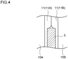
- the lock adjustment work will be described. As illustrated in Fig. 4 , in the lock adjustment work, the sliding doors 10 are driven to be closed with a door trapping adjustment jig 5 disposed on the opening/closing path of the sliding doors 10, and whether locking is detected when the door end rubbers 11A and 11B sandwich the door trapping adjustment jig 5 having a predetermined thickness is determined. In the lock adjustment work, the door trapping adjustment jig 5 having a thickness for position adjustment for locking is used. If locking is detected, it is regarded that locking is done appropriately, and the lock adjustment work is done. Meanwhile, if locking is not detected (or if door trapping is detected), the attachment position of the sliding doors 10 is adjusted in the locked state, for example.
- the relative position between a lock pin (not illustrated) of the lock device 50 and a hole (not illustrated) of the sliding door 10 in a state of sandwiching the door trapping adjustment jig 5 by the door end rubbers 11 is adjusted.
- the lock pin can be inserted in the hole of the sliding door 10 to lock the sliding door 10 with the door trapping adjustment jig 5 sandwiched by the door end rubbers 11.
- whether locking is detected is determined again using the door trapping adjustment jig 5.
- the position adjustment work of the sliding doors 10 is repeated until locking is detected.
- the door trapping adjustment work will be described.
- a work basically similar to the lock adjustment work is performed except that a door trapping adjustment jig 5 having a thickness different from that for the lock adjustment work is used.
- the door trapping adjustment jig 5 having a thickness for door trapping adjustment is used. If door trapping is detected when the door end rubbers 11A and 11B sandwich the door trapping adjustment jig 5 (or if locking is not detected), it is regarded that detection of door trapping functions appropriately, and the door trapping adjustment work is done. Meanwhile, if door trapping is not detected (or if locking is detected), the position adjustment work for the sliding doors 10 is repeated until door trapping is detected.
- the position adjustment work is performed so as both locking and door trapping are appropriately detected.
- the present inventors have found that by using the following method, whether position adjustment of the sliding door 10 is necessary can be determined without an operator going in front of the sliding door opening and closing device 1. This method will be described in detail below.
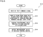
- Fig. 5 is a flowchart illustrating an operation S10 for assisting determination on whether position adjustment of the sliding door 10 is necessary.
- the drive control unit 101 receives a test command signal from the vehicle control device 2 via the communication unit 107.
- This test command signal is transmitted from the vehicle control device 2 to the door control device 100 provided at at least one boarding doorway of a train in response to an input given by a user to the vehicle control device 2, for example, at the time of safety inspection of the sliding door opening and closing device 1 by a railway company.
- the drive control unit 101 moves the sliding doors 10A and 10B to the fully closed position so as to bring the door end rubber 11 into contact with the opposing door end rubber 11.
- the drive control unit 101 further moves the sliding door 10 from the fully closed position by a predetermined distance in the direction of pressing the sliding door against the opposing door end rubber 11, thereby moving the sliding door 10 to a test position.
- the drive control unit 101 stops the sliding door 10 not to move in the pressing direction. Moving the sliding door 10 to the test position to largely deform the door end rubbers 11A and 11B in this manner simulates a state of the door end rubbers 11A and 11B sandwiching the door trapping adjustment jig 5.
- the measurement value acquisition unit 102 acquires a measurement value related to the load in the opening direction applied to the sliding door 10 when the sliding door 10 is moved to the test position in S12.
- the hardness of the door end rubber 11, the anti-vibration rubber 13, the resin door roller 22, and the like changes depending on external factors such as ambient temperature and humidity.
- the load in the opening direction applied to the sliding door 10 at the test position varies depending on the hardness of the door end rubber 11, the anti-vibration rubber 13, the door roller 22, and the like.
- the hardness of the door end rubber 11 affects the magnitude of the repulsive force produced by the pressed and deformed door end rubber 11, and the hardness of the anti-vibration rubber 13, the door roller 22, and the like affects the magnitude of the resistance against the opening or closing sliding door 10.
- the hardness of the door end rubber 11 affects the magnitude of the repulsive force produced by the pressed and deformed door end rubber 11, and the hardness of the anti-vibration rubber 13, the door roller 22, and the like affects the magnitude of the resistance against the opening or closing sliding door 10.
- a drive current of the motor 41 included in the drive unit 40 is acquired as the measurement value related to the load.
- the load of the motor 41 used in the drive unit 40 increases, and eventually, the duty ratio of the drive voltage of the motor 41 increases, resulting in the increase in the drive current of the motor 41. Accordingly, the load applied to the sliding door 10 can be estimated based on the drive current of the motor 41.
- the measurement value acquisition unit 102 supplies the acquired measurement value related to the load to the measurement value output unit 103.
- the measurement value output unit 103 outputs the supplied measurement value to the vehicle control device 2. As a result, the measurement value is displayed on a display unit (not illustrated) of the vehicle control device 2.
- the sliding door opening and closing device 1 of the present embodiment outputs the measurement value related to the load applied to the sliding door 10 when the sliding door 10 is driven in the direction of pressing the sliding door 10 against an opposing object under a predetermined operating condition with the door end rubber 11 in contact with the opposing object (the opposing door end rubber 11 in the present embodiment).
- the predetermined operating condition of the present embodiment is moving the sliding door 10 by a predetermined distance. According to the present embodiment, since an operator can grasp how easily the sliding door 10 can move in the closing direction under the assumption that the door end rubbers 11A and 11B are sandwiching the door trapping adjustment jig 5, the measurement value can be used as a guide for determining whether position adjustment of the sliding door 10 is necessary.
- the opposing object is the door end rubber (for example, the door end rubber 11B) of the other door (for example, the sliding door 10B).
- the opposing object may be a door receiving part.
- the drive control unit 101 controls the drive current flowing through the motor 41 included in the drive unit 40, and the measurement value acquisition unit 102 acquires the drive current as the measurement value related to the load. According to the present configuration, whether position adjustment of the sliding door 10 is necessary can be determined with an existing configuration without providing an additional sensor for measuring the measurement value related to the load.
- the sliding door position adjustment assisting system of the present embodiment includes a plurality of door control devices 100, and the vehicle control device 2 that outputs a test command signal to at least one of a plurality of door control devices 100.
- test command signals can be output to the door control devices 100 at a time, so that whether the position adjustment is necessary for each of a plurality of the sliding doors 10 can be determined at a time.
- the work load for determining whether the position adjustment of the sliding doors 10 is necessary can be reduced.
- the sliding door 10 provided in the railway vehicle is taken as an example, but the sliding door 10 may be provided on a platform.
- the double sliding door 10 is taken as an example, but the present invention is not limited to this configuration.
- the door may be a single sliding door.
- the opposing object may be, for example, a door receiving part.
- the measurement value related to the load applied to the sliding door 10 is acquired when the sliding door 10 is moved by the predetermined distance with the door end rubber 11 in contact with the opposing object.
- the present invention is not limited to this configuration.
- a measurement value related to the moving distance of the sliding door 10 that is driven in the direction of pressing the sliding door 10 against the opposing object so as to apply a predetermined load to the sliding door 10 with the door end rubber 11 in contact with the opposing object may be acquired.
- the measurement value related to the moving distance of the sliding door 10 may be acquired using a stroke sensor that detects the stroke of the sliding door 10.
- a plurality of limit switches that is pressed by the sliding door 10 moving to the closing direction side from the fully closed position may be provided at a plurality of positions in the closing direction side, and measurement values each related to the moving distance of the sliding door 10 may be acquired for the limit switch that is pressed. Both the measurement value related to the load and the measurement value related to the moving distance may be acquired.
- the drive current of the motor 41 is measured as the measurement value related to the load applied to the sliding door 10.
- a load sensor such as a load cell may be provided at a place where the load sensor can be sandwiched by the sliding door 10 and an object opposing the sliding door 10 (for example, the door end rubber 11), and the measurement value of the load sensor may be used as the measurement value related to the load applied to the sliding door 10.
- the torque of the motor 41 measured using a torque sensor may be the measurement value related to the load applied to the sliding door 10.
- the electric motor 41 is used in the drive unit 40, but an air cylinder that drives the sliding door 10 in the opening/closing direction using compressed air may be used.
- a measurement value related to the load is acquired using a load sensor such as a load cell or a torque sensor.
- the measurement value is output to the vehicle control device 2.
- the present invention is not limited to this configuration.
- the measurement value may be output to an external terminal device or the like carried by an operator. The same applies to a comparison result and a necessity determination result for position adjustment, which will be described later in the following embodiments.
- the door close switch 61 is provided with the test limit switch to detect whether the sliding door 10 has come to the test position.
- a door close switch for detecting the fully closed state and a door close switch for a test to detect the sliding door 10 having come to the test position may be provided in parallel.
- a stroke sensor for detecting the stroke of the sliding door 10 may be used to determine whether the sliding door 10 has come to the test position.
- whether the sliding door 10 has come to the test position may be determined based on an output signal of an encoder of the motor 41.
- a door control device 100 of the present embodiment further includes a storage unit 108, a reference value setting unit 109, and a comparison result output unit 110.
- the reference value setting unit 109 of the present embodiment is an example of an update unit.
- a vehicle control device 2 of the present embodiment is configured to be able to transmit a first test command signal and a second test command signal, described later, to the door control device 100.
- Fig. 7 is a flowchart illustrating an operation S20 for assisting determination on whether position adjustment of a sliding door 10 is necessary.
- a drive control unit 101 receives a test command signal from the vehicle control device 2 via a communication unit 107.
- the test command signal received in S21 is the first test command signal or the second test command signal.
- the first test command signal is transmitted from the vehicle control device 2 in response to an input given by a user to the vehicle control device 2.
- the position adjustment work is performed, for example, when a sliding door opening and closing device 1 is outfitted to a railway vehicle or when an operator determines that the position adjustment work is necessary at safety inspection or the like.
- the second test command signal is transmitted from the vehicle control device 2 in response to an input given by a user to the vehicle control device 2 when, for example, determination on whether the position adjustment work is necessary is to be made. Since S22 and S23 are respectively similar to S12 and S13 described above, description on S22 and S23 will be omitted.
- a measurement value output unit 103 determines whether the test command signal received in step S21 is a first test command signal or a second test command signal. If the received test command signal is a first test command signal, the measurement value output unit 103 outputs the supplied measurement value to the reference value setting unit 109, and the operation S20 proceeds to S25. If the received test command signal is a second test command signal, the measurement value output unit 103 outputs the supplied measurement value to the comparison result output unit 110, and the operation S20 proceeds to S26.
- the reference value setting unit 109 sets or updates the reference value by storing the supplied measurement value in the storage unit 108 as a reference value. Specifically, the reference value setting unit 109 sets the measurement value as the reference value when the reference value has not yet been set, for example, when position adjustment is performed when the sliding door opening and closing device 1 is outfitted to a railway vehicle. For example, when the reference value has already been set, the reference value setting unit 109 updates the reference value using the measurement value.
- the first test command signal is transmitted after completion of the position adjustment work for the sliding door 10, and in response to the first test command signal, the measurement value after the completion is set as the reference value or the reference value is updated to be the measurement value.
- the set or updated reference value indicates a value for a state in which locking and door trapping detection appropriately function.
- the comparison result output unit 110 outputs a comparison result between the supplied measurement value and the reference value predetermined in S25 to the vehicle control device 2 via the communication unit 107.
- the predetermined reference value is read from the storage unit 108.
- the comparison result of the present embodiment indicates, for example, a difference of the reference value from the measurement value.
- the comparison result is output to the vehicle control device 2, the difference is reported as the comparison result. Specifically, the difference is displayed on a display unit of the vehicle control device 2.
- the comparison result output unit 110 outputs the comparison result between the output measurement value and the predetermined reference value. According to this configuration, the degree of deviation of the measurement value from the reference value can be grasped by referring to the comparison result of the measurement value with respect to the predetermined reference value, so that determination on whether the position adjustment is necessary can be made more easily.
- the drive control unit 101 controls the drive unit 40 to press the door end rubber 11 against the opposing door end rubber 11 again in S22 after the position adjustment of the sliding door 10 is completed.
- a measurement value acquisition unit 102 acquires the measurement value at the time of the door end rubber 11 being pressed again.
- the reference value setting unit 109 updates the reference value to be the measurement value at the time of the door end rubber 11 being pressed again.
- the comparison result output unit 110 informs of a difference of the reference value from the measurement value.
- the difference takes a positive value (when the measurement value is larger than the reference value)
- the position adjustment work of the sliding door 10 is to be made so as to attach the sliding door 10 further to the opening direction side.
- the difference takes a negative value (when the measurement value is smaller than the reference value)
- the sliding door 10 that has trapped a foreign object can move less easily in the closing direction than the sliding door 10 in the reference state.
- the position adjustment work of the sliding door 10 is to be made so as to attach the sliding door 10 further to the closing direction side. Furthermore, to what degree the attachment position of the sliding door 10 is to be adjusted in order to make locking and door trapping detection function appropriately can be grasped based on the magnitude of the difference. Accordingly, the workload for the position adjustment work of the sliding door 10 can be reduced.
- the comparison result output unit 110 may use, as the reference value, a different measurement value measured at the same air temperature as when the measurement value is measured.
- a measurement value may be acquired in advance for each temperature, and each of the measurement values may be stored in association with the respective temperature in the storage unit 108.
- reference to the comparison result between the measurement value and the reference value at the same temperature can be used as a guide for determining whether any abnormality has occurred in the sliding door opening and closing device 1 (for example, lack of grease or breakage of a door roller 22, breakage of a pinion gear of a sliding door drive mechanism 42, or abnormality of a motor 41).
- the comparison result output unit 110 may report the comparison result between the temperature at which the measurement value is acquired and the temperature at which the measurement value used for setting or updating the reference value in S25 is acquired. According to this configuration, to which side, the opening direction or the closing direction, the attachment position of the sliding door 10 is to be adjusted depending on the temperature level can be grasped in the position adjustment work based on the comparison result of the temperature. As a result, the workload for the position adjustment work can be reduced.
- the comparison result output unit 110 may output the comparison result indicating that the measurement value is larger or smaller than the reference value.
- the reference value is updated in S25.
- a predetermined reference value such as a reference value defined using, for example, the measurement value at the time of outfitting the sliding door opening and closing device 1 may be kept, without updating the reference value.
- the comparison result indicates the difference of the reference value from the measurement value.
- the present invention is not limited to this configuration. For example, data in which the measurement value and the reference value are arranged in parallel may be indicated.
- a third embodiment of the present embodiment will be described below.
- the same or equivalent components and members as those of the second embodiment are denoted by the same reference numerals.
- the description same as that on the second embodiment will be omitted as appropriate, and the configuration different from that of the second embodiment will be mainly described.
- a door control device 100 of the present embodiment further includes a determination result reporting unit 111.
- Fig. 9 is a flowchart illustrating an operation S30 for assisting determination on whether position adjustment of a sliding door 10 is necessary. Since S31 to S35 are respectively similar to S21 to S25 described above, description on S31 to S35 will be omitted.
- a comparison result output unit 110 outputs a comparison result between a supplied measurement value and the reference value predetermined in S35 is output to the determination result reporting unit 111.
- the comparison result of the present embodiment is data indicating whether the measurement value is within a predetermined range from the reference value.
- the predetermined range is set based on, for example, the thickness of a door trapping adjustment jig 5 for a lock adjustment work and the thickness of a door trapping adjustment jig 5 for a door trapping adjustment work.
- the predetermined range is not limited to such setting, and is appropriately set based on an operating method or the like of a sliding door opening and closing device 1.
- the determination result reporting unit 111 determines whether the position adjustment of the sliding door 10 is necessary based on the comparison result.
- the determination result reporting unit 111 of the present embodiment determines whether the measurement value is within the predetermined range from the reference value. That the measurement value is not within the predetermined range from the reference value is, for example, the measurement value exceeding an upper limit threshold that is above the reference value by the predetermined range or falling below a lower limit threshold that is below the reference value by the predetermined range. That the measurement value is within the predetermined range from the reference value is, for example, the measurement value being equal to or smaller than the upper limit threshold and equal to or larger than the lower limit threshold.
- the determination result reporting unit 111 determines that the position adjustment of the sliding door 10 is necessary, and the operation S30 proceeds to S38. If the measurement value is within the predetermined range from the reference value, the determination result reporting unit 111 determines that the position adjustment of the sliding door 10 is not necessary, and the operation S30 proceeds to S39.
- the determination result reporting unit 111 reports that the position adjustment of the sliding door 10 is necessary. Specifically, the determination result reporting unit 111 outputs a necessity determination result indicating that the position adjustment of the sliding door 10 is necessary to a vehicle control device 2 via a communication unit 107. As a result, the necessity determination result is displayed on a display unit of the vehicle control device 2. After S38, the operation S30 ends.
- the determination result reporting unit 111 reports that the position adjustment of the sliding door 10 is not necessary. Specifically, the determination result reporting unit 111 outputs the necessity determination result indicating that the position adjustment of the sliding door 10 is not necessary to the vehicle control device 2 via the communication unit 107. As a result, the necessity determination result is displayed on a display unit of the vehicle control device 2. After S39, the operation S30 ends.
- the determination result reporting unit 111 reports the necessity determination result for the position adjustment of the sliding door 10 based on the comparison result. According to this configuration, the reporting on the necessity determination result for the position adjustment of the sliding door 10 makes the determination on whether the position adjustment of the sliding door 10 is necessary further easy.
- whether the position adjustment of the sliding door 10 is necessary is determined by whether the measurement value is within the predetermined range from the reference value.
- the present invention is not limited this configuration.
- whether the position adjustment of the sliding door 10 is necessary may be determined by whether the difference of the reference value from the measurement value is larger than a predetermined threshold.
- a door control device 100A of the present embodiment further includes a request unit 112, an adjacent sliding door information acquisition unit 113, and an adjacent sliding door information reporting unit 114.
- a sliding door 10 that is controlled to be opened and closed by the door control device 100A is an example of a first sliding door that opens and closes one of a plurality of boarding doorways to a railway vehicle.
- a sliding door 10 that opens and closes a boarding doorway adjacent to the boarding doorway provided with the first sliding door 10 is an example of a second sliding door.
- An adjacent door control device 100B in Fig. 10 controls opening and closing of the second sliding door 10.
- the adjacent door control device 100B has a similar configuration as the door control device 100A. In the present embodiment, it is assumed that second test command signals are transmitted to the door control device 100A and the adjacent door control device 100B at a time.
- the request unit 112 receives the second test command signal via a communication unit 107, and in response to the second test command signal transmits a request signal for requesting the adjacent door control device 100B of a necessity determination result for position adjustment. As a result, after the adjacent door control device 100B acquires the necessity determination result, the adjacent door control device 100B transmits the necessity determination result.
- the adjacent sliding door information acquisition unit 113 acquires the necessity determination result for the second sliding door 10 from the adjacent door control device 100B via the communication unit 107. The adjacent sliding door information acquisition unit 113 supplies the acquired necessity determination result to the adjacent sliding door information reporting unit 114.
- the adjacent sliding door information reporting unit 114 determines whether the necessity determination result for the position adjustment of the first sliding door 10 matches the necessity determination result for the position adjustment of the second sliding door 10. If these necessity determination results do not match, the adjacent sliding door information reporting unit 114 reports to a vehicle control device 2 via the communication unit 107 that the necessity determination result for the position adjustment of the second sliding door 10.
- the present embodiment can prompt checking of whether any abnormality has occurred in a sliding door opening and closing device 1 using the necessity determination result for the position adjustment of the second sliding door 10 adjacent to the first sliding door 10 as reference information.
- the adjacent sliding door information acquisition unit 113 acquires the necessity determination result for the position adjustment.
- the adjacent sliding door information acquisition unit 113 may acquire the measurement value for the second sliding door 10.
- the adjacent sliding door information reporting unit 114 may determine whether the degree of deviation between the measurement value for the first sliding door 10 and the measurement value for the second sliding door 10 exceeds a predetermined range. For example, when the difference or ratio between the measurement values is larger than a predetermined threshold, the adjacent sliding door information reporting unit 114 determines that the degree of deviation exceeds the predetermined range. If the adjacent sliding door information reporting unit 114 determines that the degree of deviation exceeds the predetermined range, the adjacent sliding door information reporting unit 114 may just report the measurement value for the second sliding door 10.
- the present invention is not limited to this configuration.
- the second test command signal is not transmitted to the adjacent door control device 100B, but is transmitted to the door control device 100A.
- the adjacent door control device 100B may transmit the measurement value or the necessity determination result obtained most recently in response to the request signal.
- a fifth embodiment of the present embodiment will be described below.
- the same or equivalent components and members as those of the first embodiment are denoted by the same reference numerals.
- the description same as that on the first embodiment will be omitted as appropriate, and the configuration different from that of the first embodiment will be mainly described.
- a door control device 100 of the present embodiment further includes a storage unit 108 and a prediction unit 115.
- a measurement value output unit 103 supplies the measurement value to the storage unit 108 to store the measurement value.
- the measurement value for each measurement is accumulated in the storage unit 108.
- the measurement value output unit 103 supplies the measurement value to the prediction unit 115.
- the prediction unit 115 reads, for example, the measurement value at the previous measurement from the storage unit 108, and predicts the timing at which the position adjustment of the sliding door 10 is necessary based on comparison between the measurement value at the previous measurement and the measurement value at the current measurement. For example, the prediction unit 115 obtains the temporal change amount of the measurement value based on the elapsed time from the previous measurement to the current measurement and the difference between the measurement value at the previous measurement and the measurement value at the current measurement. The prediction unit 115 predicts the timing by obtaining the time until the measurement value at the current measurement reaches a predetermined threshold based on the obtained temporal change amount.
- the prediction unit 115 predicts the timing at which the position adjustment of the sliding door 10 is necessary based on the comparison between the measurement value acquired at a first time point and the measurement value acquired at a second time point earlier than the first time point. According to the present embodiment, the timing when the position adjustment of the sliding door 10 is necessary can be grasped.
- the prediction is made based on the comparison between the measurement value at the previous measurement and the measurement value at the current measurement.
- the measurement values may be those measured earlier than the measurement value at the current measurement.
- the above prediction may be made based on comparison among three or more measurement values.
- the present invention relates to a sliding door position adjustment assisting device and a sliding door position adjustment assisting system.
Landscapes
- Engineering & Computer Science (AREA)
- Mechanical Engineering (AREA)
- Transportation (AREA)
- Power-Operated Mechanisms For Wings (AREA)
Abstract
Description
- The present invention relates to a sliding door position adjustment assisting device and a sliding door position adjustment assisting system.
- To minimize accidents such as dragging of a stroller, techniques related to detecting door trapping have gained higher attention.
JP 2019-105144 A JP 2019-105144 A - PATENT LITERTURE 1:
Japanese Unexamined Patent Application Publication No. 2019-105144 - The hardness of a rubber member such as a door end rubber used in a door trapping detection system is easily affected by external factors such as temperature and humidity. When a sliding door opening and closing device continues its operation with the hardness of the rubber member greatly changed by temperature and humidity, detection of door trapping may not function appropriately. In this regard, the sliding door opening and closing device is subjected to a work of adjusting the attached position of the sliding door so that the detection of door trapping functions is appropriately obtained.
- Conventionally, the position adjustment work requires an operator to actually go in front of all the sliding door opening and closing devices to check whether door trapping can be appropriately detected. This means that all the sliding doors of a train need to be checked, which requires a lot of time.
- In view of the above problem, an object of the present disclosure is to provide a sliding door position adjustment assisting device and a sliding door position adjustment assisting system that enable determining whether a position adjustment work is needed for a sliding door without requiring an operator to go in front of a sliding door opening and closing device.
- To solve the problem described above, a sliding door position adjustment assisting device according to some aspect of the present disclosure includes: a drive control unit configured to move a sliding door in an opening/closing direction by controlling a drive unit; a measurement value acquisition unit configured to acquire a measurement value related to at least one of a moving distance of the sliding door or a load applied to the sliding door, the measurement value being measured when the sliding door is driven in a direction of pressing the sliding door against an opposing object under a predetermined operating condition by the drive control unit with a door end rubber provided at a door end of the sliding door being in contact with the opposing object; and a measurement value output unit configured to output the measurement value acquired by the measurement value acquisition unit.
- A sliding door position adjustment assisting system according to another aspect of the present disclosure includes: a plurality of information output devices provided at a platform or a vehicle, and used for a plurality of sliding doors that open and close a plurality of boarding doorways to a vehicle, the information output devices being configured to execute, in response to a command signal, an operation of moving the sliding door in an opening/closing direction by controlling a drive unit, an operation of acquiring a measurement value related to at least one of a moving distance of the sliding door or a load applied to the sliding door, the measurement value being measured when the sliding door is driven in a direction of pressing the sliding door against an opposing object under a predetermined operating condition with a door end rubber provided at a door end of the sliding door being in contact with the opposing object, and an operation of outputting the measurement value that has been acquired; and a command device configured to output the command signal for causing at least one of the plurality of information output devices to execute the operation of moving, the operation of acquiring, and the operation of outputting.
- Note that, any combination of the above aspects and any aspect in which the component or expression of the aspect of the present invention, such as method, device, program, temporary or non-temporary storage medium in which a program is stored, and system, is replaced with any one of those of a different aspect of the present invention are also effective as aspects of the present invention.
- According to the present invention, whether position adjustment work is needed for a sliding door can be determined without requiring an operator to go in front of a sliding door opening and closing device.
-
-
Fig. 1 is a front view schematically illustrating a configuration of a sliding door opening and closing device; -
Fig. 2 is a cross-sectional view taken along line A-A inFig. 1 ; -
Fig 3 is a block diagram of a door control device according to a first embodiment; -
Fig. 4 is a view for explaining a position adjustment work for a sliding door; -
Fig. 5 is a flowchart illustrating an operation of the door control device according to the first embodiment; -
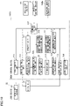
Fig 6 is a block diagram of a door control device according to a second embodiment; -
Fig. 7 is a flowchart illustrating an operation of the door control device according to the second embodiment; -
Fig 8 is a block diagram of a door control device according to a third embodiment; -
Fig. 9 is a flowchart illustrating an operation of the door control device according to the third embodiment; -
Fig. 10 is a block diagram of a door control device according to a fourth embodiment; and -
Fig. 11 is a block diagram of a door control device according to a fifth embodiment. - In the following embodiments and exemplary modifications, the same or equivalent components or members are denoted by the same reference numerals, and redundant description will be omitted as appropriate. The dimensions of the members in each drawing are appropriately enlarged or reduced in order to facilitate understanding. In each drawing, some of members that are not important for describing the embodiment are omitted.
-
Figs. 1 and2 are referred. A railway vehicle is provided with a sliding door opening andclosing device 1 for opening and closing a boarding doorway of the railway vehicle. The sliding door opening andclosing device 1 includes a pair of left and right sliding doors 10 (10A and 10B), arail moving body 20, a slidingdoor rail 30, adrive unit 40, alock device 50, a doorclose switch 61, adoor lock switch 62, and adoor control device 100. Thedoor control device 100 can communicate with, for example, avehicle control device 2 provided in a driver's room of the railway vehicle. Thedoor control device 100 of the present embodiment is an example of a sliding door position adjustment assisting device and an information output device. - The
vehicle control device 2 is a higher-level device of thedoor control device 100, and is configured to be able to transmit an open/close command signal for controlling opening and closing of the slidingdoor 10 to thedoor control device 100. Thevehicle control device 2 of the present embodiment is configured to be able to transmit a test command signal, described later, to thedoor control device 100. Thevehicle control device 2 of the present embodiment is an example of a command device. Thevehicle control device 2 and thedoor control device 100 of the present embodiment exemplify a sliding door position adjustment assisting system. - A pair of sliding
doors doors doors rail moving body 20. Each of the slidingdoors door 10 is at a fully closed position, thedoor end rubber 11 abuts tightly with the opposingdoor end rubber 11 to close a gap between the door ends of the slidingdoors door 10 at a fully open position is accommodated in adoor pocket 12. Ananti-vibration rubber 13 is provided in a gap between the slidingdoor 10 and thedoor pocket 12. Theanti-vibration rubber 13 supports the slidingdoor 10 so as to suppress vibration of the slidingdoor 10. - The
rail moving body 20 includes adoor hanger 21, anddoor rollers 22 made of resin. Thedoor rollers 22 are provided inside thedoor hanger 21. Thedoor hanger 21 is attached to the slidingdoor 10 so as to suspend the slidingdoor 10 therefrom. Thedoor hanger 21 is attached to a slidingdoor drive mechanism 42, described later, of thedrive unit 40, and is configured to be movable, by the drive of thedrive unit 40, in the opening/closing direction along the slidingdoor rail 30. - The sliding
door rail 30 is provided to the vehicle body, above the slidingdoor 10. Thedoor hanger 21 is attached to the slidingdoor rail 30 via thedoor rollers 22. - The
drive unit 40 includes anelectric motor 41 disposed at an upper rim of a doorway of the railway vehicle, and the slidingdoor drive mechanism 42 including a rack, a pinion, and the like. Themotor 41 is connected to the slidingdoor 10 via the slidingdoor drive mechanism 42 and therail moving body 20. When an output shaft of themotor 41 rotates in one direction, the slidingdoor 10 moves in the opening direction, and when the output shaft of themotor 41 rotates in the other direction, the slidingdoor 10 moves in the closing direction. - The
lock device 50 has a function of locking a pair of slidingdoors 10 in the fully closed state not to open. Thelock device 50 is provided to each pair of slidingdoors 10. Thelock device 50 includes a lock pin (not illustrated) that can project toward and retract away from the slidingdoor 10. By the lock pin of thelock device 50 moved to the locking position and inserted in a hole (not illustrated) of the slidingdoor 10 in the fully closed state, the slidingdoor 10 is locked in an unmovable state. Note that, the present invention is not limited to this configuration. Thelock device 50 may lock the slidingdoor 10 by various known methods not to open. - The door
close switch 61 detects full closing of the slidingdoor 10. The doorclose switch 61 includes a full-close detection limit switch (not illustrated) that is pressed by the slidingdoor 10 that has moved to the fully closed position. By pressing the full-close detection limit switch, full closing of the slidingdoor 10 is detected. - The door
close switch 61 of the present embodiment detects that the slidingdoor 10 has moved from the fully closed position by a predetermined distance in the direction of pressing the slidingdoor 10 against thedoor end rubber 11 of the opposing sliding door 10 (hereinafter, this position after the movement is referred to as "test position".). The doorclose switch 61 further includes a test limit switch that is pressed by the slidingdoor 10 that has moved to the test position. By pressing the test limit switch, that the slidingdoor 10 has moved to the test position is detected. - The
door lock switch 62 is a switch that detects locking of the slidingdoor 10 by thelock device 50. Thedoor lock switch 62 includes a lock detection limit switch that is pressed by the lock pin of thelock device 50 when the lock pin has moved to the locking position. When the lock detection limit switch is pressed, locking of the slidingdoor 10 is detected. Thedoor lock switch 62 is provided inside thelock device 50, for example. - The
door control device 100 will be described with reference toFig. 3 . Each functional block illustrated in the drawing is realized, in terms of hardware, by a computer having a calculation function, a control function, a storage function, an input function, and an output function, an electronic element, a mechanical component, and the like, and in terms of software, by a computer program or the like. The illustrated functional blocks are realized by cooperation of those listed above. It is to be understood by those skilled in the art that these functional blocks can be realized in various forms by combining hardware and software. - The
door control device 100 includes adrive control unit 101, a measurementvalue acquisition unit 102, a measurementvalue output unit 103, alock control unit 104, a door trappingdetection unit 105, alock detection unit 106, and acommunication unit 107. Thedoor control device 100 of the present embodiment is provided in the vicinity of the slidingdoor 10 for all the boarding doorways of a train (seeFig. 1 ). - The
drive control unit 101 moves the slidingdoor 10 in the opening/closing direction by controlling thedrive unit 40. Thedrive control unit 101 of the present embodiment is configured to drive the slidingdoor 10 further in the closing direction from the fully closed position of the slidingdoor 10 in response to a test command signal, described later, supplied via thecommunication unit 107. Thedrive control unit 101 of the present embodiment controls the driving of the slidingdoor 10 in the opening/closing direction by controlling the drive current flowing through themotor 41 included in thedrive unit 40. - The measurement
value acquisition unit 102 acquires a predetermined measurement value, described later. The measurementvalue acquisition unit 102 of the present embodiment acquires a drive current as a measurement value related to a load. - The measurement
value output unit 103 outputs the measurement value acquired by the measurementvalue acquisition unit 102. The measurementvalue output unit 103 of the present embodiment outputs the measurement value to an external device such as thevehicle control device 2 via thecommunication unit 107, and displays the output result on a display screen. - The
lock control unit 104 controls thelock device 50 to lock the slidingdoor 10 when the slidingdoor 10 is fully closed. For example, thelock control unit 104 locks the slidingdoor 10 on receiving, from thevehicle control device 2 via thecommunication unit 107, a lock command signal for locking the slidingdoor 10. The lock command signal is output by thevehicle control device 2, for example, when thevehicle control device 2 receives a detection signal indicating the slidingdoor 10 has been fully closed from all the door close switches 61 provided at the boarding doorways. Thelock control unit 104 controls thelock device 50 to unlock the slidingdoor 10. Note that, thedrive control unit 101 may send a command for driving thelock device 50 to thelock control unit 104 to control thelock device 50. - The door trapping
detection unit 105 detects door trapping when a foreign object (including a person, a part of a person, and an object.) is sandwiched by the door end of the slidingdoor 10 and the slidingdoor 10 cannot be locked (a door trapping state). For example, the door trappingdetection unit 105 detects the door trapping state when the rotation of themotor 41 stops during the closing drive of the slidingdoor 10 when the slidingdoor 10 is not yet locked by thelock device 50. The thickness of an object by which door trapping is detected (hereinafter, referred to as a door trapping detection thickness) can be adjusted by adjusting the attachment position of the slidingdoor 10. On detecting door trapping, the door trappingdetection unit 105 transmits a door trapping detection signal to thevehicle control device 2 via thecommunication unit 107 to report the door trapping. - The
lock detection unit 106 detects locking of the slidingdoor 10 by thelock device 50. For example, thelock detection unit 106 detects locking of the slidingdoor 10 in response to thedoor lock switch 62 detecting the locking of the slidingdoor 10. The thickness of an object by which locking is detected (hereinafter, referred to as a lock detection thickness) can be adjusted by adjusting the attachment position of the slidingdoor 10. On detecting locking, thelock detection unit 106 transmits a lock detection signal to thevehicle control device 2 via thecommunication unit 107 to report the locking. - The
communication unit 107 communicates with an external device. Thecommunication unit 107 of the present embodiment is configured to be able to communicate with thevehicle control device 2. - Hereinafter, the position adjustment work of the sliding
door 10 will be described. The softness (or hardness) of thedoor end rubber 11, theanti-vibration rubber 13, theresin door roller 22, and the like changes depending on external factors such as ambient temperature and humidity. For example, when thedoor end rubber 11 softens due to the rise in the outside air temperature, thedoor end rubbers doors anti-vibration rubber 13, thedoor roller 22, and the like reduces the resistance against the opening orclosing sliding door 10, which allows the slidingdoors door end rubber 11 hardens due to the decrease in the outside air temperature, thedoor end rubbers doors anti-vibration rubber 13, thedoor roller 22, and the like increases the resistance against opening and closing of the slidingdoor 10, which makes it difficult for the slidingdoors 10 to approach each other. In this case, even when it is originally set that locking is performed with a foreign object having a thickness of D2 mm trapped, for example, such a case may happen that locking is not performed although a foreign matter having a thickness of D2 mm is actually trapped, and door trapping is detected. Although a train can usually depart with just a thin object trapped in the slidingdoors 10, departure is suspended by repeated detection of door trapping, and this adversely affects on-time performance. As described above, locking and detecting of door trapping may not function appropriately depending on ambient temperature, humidity, or the like. To address this problem, a work of adjusting the attachment position of the sliding door 10 (position adjustment work) is performed at a safety inspection or in each season, for example. - In the position adjustment work, the sliding door opening and
closing device 1 is attached to the railway vehicle first. Then, a lock adjustment work of adjusting the lock detection thickness and a door trapping adjustment work of adjusting the door trapping detection thickness are performed. - The lock adjustment work will be described. As illustrated in
Fig. 4 , in the lock adjustment work, the slidingdoors 10 are driven to be closed with a door trappingadjustment jig 5 disposed on the opening/closing path of the slidingdoors 10, and whether locking is detected when thedoor end rubbers adjustment jig 5 having a predetermined thickness is determined. In the lock adjustment work, the door trappingadjustment jig 5 having a thickness for position adjustment for locking is used. If locking is detected, it is regarded that locking is done appropriately, and the lock adjustment work is done. Meanwhile, if locking is not detected (or if door trapping is detected), the attachment position of the slidingdoors 10 is adjusted in the locked state, for example. By this work, the relative position between a lock pin (not illustrated) of thelock device 50 and a hole (not illustrated) of the slidingdoor 10 in a state of sandwiching the door trappingadjustment jig 5 by the door end rubbers 11 is adjusted. By this adjustment, the lock pin can be inserted in the hole of the slidingdoor 10 to lock the slidingdoor 10 with the door trappingadjustment jig 5 sandwiched by the door end rubbers 11. Then, whether locking is detected is determined again using the door trappingadjustment jig 5. The position adjustment work of the slidingdoors 10 is repeated until locking is detected. - The door trapping adjustment work will be described. In the door trapping adjustment work, a work basically similar to the lock adjustment work is performed except that a door trapping
adjustment jig 5 having a thickness different from that for the lock adjustment work is used. In the door trapping adjustment work, the door trappingadjustment jig 5 having a thickness for door trapping adjustment is used. If door trapping is detected when thedoor end rubbers doors 10 is repeated until door trapping is detected. - As described above, the position adjustment work is performed so as both locking and door trapping are appropriately detected.
- However, in a conventional position adjustment work, an operator needs to go in front of all the sliding door opening and
closing devices 1 to sandwich the door trappingadjustment jig 5 by thedoor end rubbers 11 to determine whether position adjustment of the slidingdoors 10 is necessary. This means that all the slidingdoors 10 of a train need to be checked, which requires a lot of time. - The present inventors have found that by using the following method, whether position adjustment of the sliding
door 10 is necessary can be determined without an operator going in front of the sliding door opening andclosing device 1. This method will be described in detail below. - An operation of the
door control device 100 of the present embodiment will be described with reference toFig. 5. Fig. 5 is a flowchart illustrating an operation S10 for assisting determination on whether position adjustment of the slidingdoor 10 is necessary. - In S11, the
drive control unit 101 receives a test command signal from thevehicle control device 2 via thecommunication unit 107. This test command signal is transmitted from thevehicle control device 2 to thedoor control device 100 provided at at least one boarding doorway of a train in response to an input given by a user to thevehicle control device 2, for example, at the time of safety inspection of the sliding door opening andclosing device 1 by a railway company. - In S12, in response to the test command signal, the
drive control unit 101 moves the slidingdoors door end rubber 11 into contact with the opposingdoor end rubber 11. Thedrive control unit 101 further moves the slidingdoor 10 from the fully closed position by a predetermined distance in the direction of pressing the sliding door against the opposingdoor end rubber 11, thereby moving the slidingdoor 10 to a test position. In the present embodiment, when the test limit switch of the doorclose switch 61 is pressed to detect that the slidingdoor 10 is located at the test position, thedrive control unit 101 stops the slidingdoor 10 not to move in the pressing direction. Moving the slidingdoor 10 to the test position to largely deform thedoor end rubbers door end rubbers adjustment jig 5. - In S13, the measurement
value acquisition unit 102 acquires a measurement value related to the load in the opening direction applied to the slidingdoor 10 when the slidingdoor 10 is moved to the test position in S12. As described above, the hardness of thedoor end rubber 11, theanti-vibration rubber 13, theresin door roller 22, and the like changes depending on external factors such as ambient temperature and humidity. The load in the opening direction applied to the slidingdoor 10 at the test position varies depending on the hardness of thedoor end rubber 11, theanti-vibration rubber 13, thedoor roller 22, and the like. This is because the hardness of thedoor end rubber 11 affects the magnitude of the repulsive force produced by the pressed and deformeddoor end rubber 11, and the hardness of theanti-vibration rubber 13, thedoor roller 22, and the like affects the magnitude of the resistance against the opening orclosing sliding door 10. Thus, by estimating the load in the opening direction, how easily can the slidingdoor 10 move in the closing direction under the assumption that thedoor end rubbers adjustment jig 5 can be grasped. As a result, how easily door trapping and locking are detected can be grasped. - In the present embodiment, a drive current of the
motor 41 included in thedrive unit 40 is acquired as the measurement value related to the load. When the load applied to the slidingdoor 10 increases, the load of themotor 41 used in thedrive unit 40 increases, and eventually, the duty ratio of the drive voltage of themotor 41 increases, resulting in the increase in the drive current of themotor 41. Accordingly, the load applied to the slidingdoor 10 can be estimated based on the drive current of themotor 41. The measurementvalue acquisition unit 102 supplies the acquired measurement value related to the load to the measurementvalue output unit 103. - In S14, the measurement
value output unit 103 outputs the supplied measurement value to thevehicle control device 2. As a result, the measurement value is displayed on a display unit (not illustrated) of thevehicle control device 2. - Then, the operation S10 ends.
- As described above, the sliding door opening and
closing device 1 of the present embodiment outputs the measurement value related to the load applied to the slidingdoor 10 when the slidingdoor 10 is driven in the direction of pressing the slidingdoor 10 against an opposing object under a predetermined operating condition with thedoor end rubber 11 in contact with the opposing object (the opposingdoor end rubber 11 in the present embodiment). The predetermined operating condition of the present embodiment is moving the slidingdoor 10 by a predetermined distance. According to the present embodiment, since an operator can grasp how easily the slidingdoor 10 can move in the closing direction under the assumption that thedoor end rubbers adjustment jig 5, the measurement value can be used as a guide for determining whether position adjustment of the slidingdoor 10 is necessary. Thus, whether position adjustment of the slidingdoor 10 is necessary can be determined without requiring the operator to go in front of the sliding door opening andclosing device 1 to perform the work of sandwiching the door trappingadjustment jig 5 between thedoor end rubbers doors 10 of a train, so that the man-hour for the position adjustment work can be reduced. - In the present embodiment, for a case where the sliding
door 10 is one of double sliding doors (for example, the slidingdoor 10A), the opposing object is the door end rubber (for example, thedoor end rubber 11B) of the other door (for example, the slidingdoor 10B). According to the present configuration, whether position adjustment of the slidingdoor 10 is necessary can be determined with an existing configuration without providing an additional configuration for largely deforming thedoor end rubber 11. The opposing object may be a door receiving part. - In the present embodiment, the
drive control unit 101 controls the drive current flowing through themotor 41 included in thedrive unit 40, and the measurementvalue acquisition unit 102 acquires the drive current as the measurement value related to the load. According to the present configuration, whether position adjustment of the slidingdoor 10 is necessary can be determined with an existing configuration without providing an additional sensor for measuring the measurement value related to the load. - The sliding door position adjustment assisting system of the present embodiment includes a plurality of
door control devices 100, and thevehicle control device 2 that outputs a test command signal to at least one of a plurality ofdoor control devices 100. According to the present configuration, test command signals can be output to thedoor control devices 100 at a time, so that whether the position adjustment is necessary for each of a plurality of the slidingdoors 10 can be determined at a time. Thus, the work load for determining whether the position adjustment of the slidingdoors 10 is necessary can be reduced. - Exemplary modifications of the present embodiment will be described below.
- In the present embodiment, the sliding
door 10 provided in the railway vehicle is taken as an example, but the slidingdoor 10 may be provided on a platform. - In the present embodiment, the double sliding
door 10 is taken as an example, but the present invention is not limited to this configuration. The door may be a single sliding door. For a single sliding door, the opposing object may be, for example, a door receiving part. - In the present embodiment, the measurement value related to the load applied to the sliding
door 10 is acquired when the slidingdoor 10 is moved by the predetermined distance with thedoor end rubber 11 in contact with the opposing object. However, the present invention is not limited to this configuration. For example, a measurement value related to the moving distance of the slidingdoor 10 that is driven in the direction of pressing the slidingdoor 10 against the opposing object so as to apply a predetermined load to the slidingdoor 10 with thedoor end rubber 11 in contact with the opposing object may be acquired. In this case, for example, the measurement value related to the moving distance of the slidingdoor 10 may be acquired using a stroke sensor that detects the stroke of the slidingdoor 10. For example, a plurality of limit switches that is pressed by the slidingdoor 10 moving to the closing direction side from the fully closed position may be provided at a plurality of positions in the closing direction side, and measurement values each related to the moving distance of the slidingdoor 10 may be acquired for the limit switch that is pressed. Both the measurement value related to the load and the measurement value related to the moving distance may be acquired. - In the present embodiment, the drive current of the
motor 41 is measured as the measurement value related to the load applied to the slidingdoor 10. However, the present invention is not limited to this configuration. For example, a load sensor such as a load cell may be provided at a place where the load sensor can be sandwiched by the slidingdoor 10 and an object opposing the sliding door 10 (for example, the door end rubber 11), and the measurement value of the load sensor may be used as the measurement value related to the load applied to the slidingdoor 10. For example, the torque of themotor 41 measured using a torque sensor may be the measurement value related to the load applied to the slidingdoor 10. - In the present embodiment, the
electric motor 41 is used in thedrive unit 40, but an air cylinder that drives the slidingdoor 10 in the opening/closing direction using compressed air may be used. In this case, for example, a measurement value related to the load is acquired using a load sensor such as a load cell or a torque sensor. - In the present embodiment, the measurement value is output to the
vehicle control device 2. However, the present invention is not limited to this configuration. For example, the measurement value may be output to an external terminal device or the like carried by an operator. The same applies to a comparison result and a necessity determination result for position adjustment, which will be described later in the following embodiments. - In the present embodiment, the door
close switch 61 is provided with the test limit switch to detect whether the slidingdoor 10 has come to the test position. However, the present invention is not limited to this configuration. For example, a door close switch for detecting the fully closed state and a door close switch for a test to detect the slidingdoor 10 having come to the test position may be provided in parallel. For example, a stroke sensor for detecting the stroke of the slidingdoor 10 may be used to determine whether the slidingdoor 10 has come to the test position. For example, whether the slidingdoor 10 has come to the test position may be determined based on an output signal of an encoder of themotor 41. - A second embodiment of the present embodiment will be described below. In the drawing and description of the second embodiment, the same or equivalent components and members as those of the first embodiment are denoted by the same reference numerals. The description same as that on the first embodiment will be omitted as appropriate, and the configuration different from that of the first embodiment will be mainly described.
-
Fig. 6 is referred. Adoor control device 100 of the present embodiment further includes astorage unit 108, a referencevalue setting unit 109, and a comparisonresult output unit 110. The referencevalue setting unit 109 of the present embodiment is an example of an update unit. Avehicle control device 2 of the present embodiment is configured to be able to transmit a first test command signal and a second test command signal, described later, to thedoor control device 100. - An operation of the
door control device 100 of the present embodiment will be described with reference toFig. 7. Fig. 7 is a flowchart illustrating an operation S20 for assisting determination on whether position adjustment of a slidingdoor 10 is necessary. - In S21, a
drive control unit 101 receives a test command signal from thevehicle control device 2 via acommunication unit 107. The test command signal received in S21 is the first test command signal or the second test command signal. After the position adjustment work of the slidingdoor 10 is completed, the first test command signal is transmitted from thevehicle control device 2 in response to an input given by a user to thevehicle control device 2. The position adjustment work is performed, for example, when a sliding door opening andclosing device 1 is outfitted to a railway vehicle or when an operator determines that the position adjustment work is necessary at safety inspection or the like. The second test command signal is transmitted from thevehicle control device 2 in response to an input given by a user to thevehicle control device 2 when, for example, determination on whether the position adjustment work is necessary is to be made. Since S22 and S23 are respectively similar to S12 and S13 described above, description on S22 and S23 will be omitted. - In step S24, a measurement
value output unit 103 determines whether the test command signal received in step S21 is a first test command signal or a second test command signal. If the received test command signal is a first test command signal, the measurementvalue output unit 103 outputs the supplied measurement value to the referencevalue setting unit 109, and the operation S20 proceeds to S25. If the received test command signal is a second test command signal, the measurementvalue output unit 103 outputs the supplied measurement value to the comparisonresult output unit 110, and the operation S20 proceeds to S26. - In S25, the reference
value setting unit 109 sets or updates the reference value by storing the supplied measurement value in thestorage unit 108 as a reference value. Specifically, the referencevalue setting unit 109 sets the measurement value as the reference value when the reference value has not yet been set, for example, when position adjustment is performed when the sliding door opening andclosing device 1 is outfitted to a railway vehicle. For example, when the reference value has already been set, the referencevalue setting unit 109 updates the reference value using the measurement value. Here, the first test command signal is transmitted after completion of the position adjustment work for the slidingdoor 10, and in response to the first test command signal, the measurement value after the completion is set as the reference value or the reference value is updated to be the measurement value. Thus, the set or updated reference value indicates a value for a state in which locking and door trapping detection appropriately function. After S25, the operation S20 ends. - In S26, the comparison
result output unit 110 outputs a comparison result between the supplied measurement value and the reference value predetermined in S25 to thevehicle control device 2 via thecommunication unit 107. The predetermined reference value is read from thestorage unit 108. The comparison result of the present embodiment indicates, for example, a difference of the reference value from the measurement value. When the comparison result is output to thevehicle control device 2, the difference is reported as the comparison result. Specifically, the difference is displayed on a display unit of thevehicle control device 2. After S26, the operation S20 ends. - As described above, in the present embodiment, the comparison
result output unit 110 outputs the comparison result between the output measurement value and the predetermined reference value. According to this configuration, the degree of deviation of the measurement value from the reference value can be grasped by referring to the comparison result of the measurement value with respect to the predetermined reference value, so that determination on whether the position adjustment is necessary can be made more easily. - In the present embodiment, the
drive control unit 101 controls thedrive unit 40 to press thedoor end rubber 11 against the opposingdoor end rubber 11 again in S22 after the position adjustment of the slidingdoor 10 is completed. In S23, a measurementvalue acquisition unit 102 acquires the measurement value at the time of thedoor end rubber 11 being pressed again. In S25, the referencevalue setting unit 109 updates the reference value to be the measurement value at the time of thedoor end rubber 11 being pressed again. The present configuration enables further accurate determination of whether the position adjustment of the slidingdoor 10 is necessary as compared with a case, for example, where the reference value determined using the measurement value at the time of outfitting the sliding door opening andclosing device 1 is kept. - In the present embodiment, the comparison
result output unit 110 informs of a difference of the reference value from the measurement value. According to the present configuration, for example, when the difference takes a positive value (when the measurement value is larger than the reference value), it can be understood that the slidingdoor 10 that has trapped a foreign object can move more easily in the closing direction than the slidingdoor 10 in a reference state. Thus, it can be understood that the position adjustment work of the slidingdoor 10 is to be made so as to attach the slidingdoor 10 further to the opening direction side. Similarly, when the difference takes a negative value (when the measurement value is smaller than the reference value), it can be understood that the slidingdoor 10 that has trapped a foreign object can move less easily in the closing direction than the slidingdoor 10 in the reference state. Thus, it can be understood that the position adjustment work of the slidingdoor 10 is to be made so as to attach the slidingdoor 10 further to the closing direction side. Furthermore, to what degree the attachment position of the slidingdoor 10 is to be adjusted in order to make locking and door trapping detection function appropriately can be grasped based on the magnitude of the difference. Accordingly, the workload for the position adjustment work of the slidingdoor 10 can be reduced. - Exemplary modifications of the present embodiment will be described below.
- The comparison
result output unit 110 may use, as the reference value, a different measurement value measured at the same air temperature as when the measurement value is measured. In this case, a measurement value may be acquired in advance for each temperature, and each of the measurement values may be stored in association with the respective temperature in thestorage unit 108. According to this configuration, reference to the comparison result between the measurement value and the reference value at the same temperature can be used as a guide for determining whether any abnormality has occurred in the sliding door opening and closing device 1 (for example, lack of grease or breakage of adoor roller 22, breakage of a pinion gear of a slidingdoor drive mechanism 42, or abnormality of a motor 41). - The comparison
result output unit 110 may report the comparison result between the temperature at which the measurement value is acquired and the temperature at which the measurement value used for setting or updating the reference value in S25 is acquired. According to this configuration, to which side, the opening direction or the closing direction, the attachment position of the slidingdoor 10 is to be adjusted depending on the temperature level can be grasped in the position adjustment work based on the comparison result of the temperature. As a result, the workload for the position adjustment work can be reduced. The comparisonresult output unit 110 may output the comparison result indicating that the measurement value is larger or smaller than the reference value. - In the present embodiment, the reference value is updated in S25. However, a predetermined reference value such as a reference value defined using, for example, the measurement value at the time of outfitting the sliding door opening and
closing device 1 may be kept, without updating the reference value. - In the present embodiment, the comparison result indicates the difference of the reference value from the measurement value. However, the present invention is not limited to this configuration. For example, data in which the measurement value and the reference value are arranged in parallel may be indicated.
- A third embodiment of the present embodiment will be described below. In the drawing and description of the third embodiment, the same or equivalent components and members as those of the second embodiment are denoted by the same reference numerals. The description same as that on the second embodiment will be omitted as appropriate, and the configuration different from that of the second embodiment will be mainly described.
-
Fig. 8 is referred. Adoor control device 100 of the present embodiment further includes a determinationresult reporting unit 111. - An operation of the
door control device 100 of the present embodiment will be described with reference toFig. 9. Fig. 9 is a flowchart illustrating an operation S30 for assisting determination on whether position adjustment of a slidingdoor 10 is necessary. Since S31 to S35 are respectively similar to S21 to S25 described above, description on S31 to S35 will be omitted. - In S36, a comparison
result output unit 110 outputs a comparison result between a supplied measurement value and the reference value predetermined in S35 is output to the determinationresult reporting unit 111. The comparison result of the present embodiment is data indicating whether the measurement value is within a predetermined range from the reference value. The predetermined range is set based on, for example, the thickness of a door trappingadjustment jig 5 for a lock adjustment work and the thickness of a door trappingadjustment jig 5 for a door trapping adjustment work. The predetermined range is not limited to such setting, and is appropriately set based on an operating method or the like of a sliding door opening andclosing device 1. - In S37, the determination
result reporting unit 111 determines whether the position adjustment of the slidingdoor 10 is necessary based on the comparison result. The determinationresult reporting unit 111 of the present embodiment determines whether the measurement value is within the predetermined range from the reference value. That the measurement value is not within the predetermined range from the reference value is, for example, the measurement value exceeding an upper limit threshold that is above the reference value by the predetermined range or falling below a lower limit threshold that is below the reference value by the predetermined range. That the measurement value is within the predetermined range from the reference value is, for example, the measurement value being equal to or smaller than the upper limit threshold and equal to or larger than the lower limit threshold. If the measurement value is not within the predetermined range from the reference value, the determinationresult reporting unit 111 determines that the position adjustment of the slidingdoor 10 is necessary, and the operation S30 proceeds to S38. If the measurement value is within the predetermined range from the reference value, the determinationresult reporting unit 111 determines that the position adjustment of the slidingdoor 10 is not necessary, and the operation S30 proceeds to S39. - In S38, the determination
result reporting unit 111 reports that the position adjustment of the slidingdoor 10 is necessary. Specifically, the determinationresult reporting unit 111 outputs a necessity determination result indicating that the position adjustment of the slidingdoor 10 is necessary to avehicle control device 2 via acommunication unit 107. As a result, the necessity determination result is displayed on a display unit of thevehicle control device 2. After S38, the operation S30 ends. - In S39, the determination
result reporting unit 111 reports that the position adjustment of the slidingdoor 10 is not necessary. Specifically, the determinationresult reporting unit 111 outputs the necessity determination result indicating that the position adjustment of the slidingdoor 10 is not necessary to thevehicle control device 2 via thecommunication unit 107. As a result, the necessity determination result is displayed on a display unit of thevehicle control device 2. After S39, the operation S30 ends. - As described above, in the present embodiment, the determination
result reporting unit 111 reports the necessity determination result for the position adjustment of the slidingdoor 10 based on the comparison result. According to this configuration, the reporting on the necessity determination result for the position adjustment of the slidingdoor 10 makes the determination on whether the position adjustment of the slidingdoor 10 is necessary further easy. - Exemplary modifications of the present embodiment will be described below. In the present embodiment, whether the position adjustment of the sliding
door 10 is necessary is determined by whether the measurement value is within the predetermined range from the reference value. However, the present invention is not limited this configuration. For example, whether the position adjustment of the slidingdoor 10 is necessary may be determined by whether the difference of the reference value from the measurement value is larger than a predetermined threshold. - A fourth embodiment of the present embodiment will be described below. In the drawing and description of the fourth embodiment, the same or equivalent components and members as those of the third embodiment are denoted by the same reference numerals. The description same as that on the third embodiment will be omitted as appropriate, and the configuration different from that of the third embodiment will be mainly described.
-
Fig. 10 is referred. Adoor control device 100A of the present embodiment further includes arequest unit 112, an adjacent sliding doorinformation acquisition unit 113, and an adjacent sliding doorinformation reporting unit 114. A slidingdoor 10 that is controlled to be opened and closed by thedoor control device 100A is an example of a first sliding door that opens and closes one of a plurality of boarding doorways to a railway vehicle. A slidingdoor 10 that opens and closes a boarding doorway adjacent to the boarding doorway provided with the first slidingdoor 10 is an example of a second sliding door. An adjacentdoor control device 100B inFig. 10 controls opening and closing of the second slidingdoor 10. The adjacentdoor control device 100B has a similar configuration as thedoor control device 100A. In the present embodiment, it is assumed that second test command signals are transmitted to thedoor control device 100A and the adjacentdoor control device 100B at a time. - The
request unit 112 receives the second test command signal via acommunication unit 107, and in response to the second test command signal transmits a request signal for requesting the adjacentdoor control device 100B of a necessity determination result for position adjustment. As a result, after the adjacentdoor control device 100B acquires the necessity determination result, the adjacentdoor control device 100B transmits the necessity determination result. The adjacent sliding doorinformation acquisition unit 113 acquires the necessity determination result for the second slidingdoor 10 from the adjacentdoor control device 100B via thecommunication unit 107. The adjacent sliding doorinformation acquisition unit 113 supplies the acquired necessity determination result to the adjacent sliding doorinformation reporting unit 114. - The adjacent sliding door
information reporting unit 114 determines whether the necessity determination result for the position adjustment of the first slidingdoor 10 matches the necessity determination result for the position adjustment of the second slidingdoor 10. If these necessity determination results do not match, the adjacent sliding doorinformation reporting unit 114 reports to avehicle control device 2 via thecommunication unit 107 that the necessity determination result for the position adjustment of the second slidingdoor 10. - The present embodiment can prompt checking of whether any abnormality has occurred in a sliding door opening and
closing device 1 using the necessity determination result for the position adjustment of the second slidingdoor 10 adjacent to the first slidingdoor 10 as reference information. - Exemplary modifications of the present embodiment will be described below.
- In the present embodiment, the adjacent sliding door
information acquisition unit 113 acquires the necessity determination result for the position adjustment. However, the adjacent sliding doorinformation acquisition unit 113 may acquire the measurement value for the second slidingdoor 10. In this case, the adjacent sliding doorinformation reporting unit 114 may determine whether the degree of deviation between the measurement value for the first slidingdoor 10 and the measurement value for the second slidingdoor 10 exceeds a predetermined range. For example, when the difference or ratio between the measurement values is larger than a predetermined threshold, the adjacent sliding doorinformation reporting unit 114 determines that the degree of deviation exceeds the predetermined range. If the adjacent sliding doorinformation reporting unit 114 determines that the degree of deviation exceeds the predetermined range, the adjacent sliding doorinformation reporting unit 114 may just report the measurement value for the second slidingdoor 10. - In the present embodiment, an example in which the second test command signals are transmitted to the
door control device 100A and the adjacentdoor control device 100B at a time is described. However, the present invention is not limited to this configuration. For example, it may be configured that the second test command signal is not transmitted to the adjacentdoor control device 100B, but is transmitted to thedoor control device 100A. In this case, the adjacentdoor control device 100B may transmit the measurement value or the necessity determination result obtained most recently in response to the request signal. - A fifth embodiment of the present embodiment will be described below. In the drawing and description of the fifth embodiment, the same or equivalent components and members as those of the first embodiment are denoted by the same reference numerals. The description same as that on the first embodiment will be omitted as appropriate, and the configuration different from that of the first embodiment will be mainly described.
-
Fig. 11 is referred. Adoor control device 100 of the present embodiment further includes astorage unit 108 and aprediction unit 115. In the present embodiment, every time a measurement value is supplied from a measurementvalue acquisition unit 102, a measurementvalue output unit 103 supplies the measurement value to thestorage unit 108 to store the measurement value. As a result, the measurement value for each measurement is accumulated in thestorage unit 108. The measurementvalue output unit 103 supplies the measurement value to theprediction unit 115. - When the measurement value is supplied, the
prediction unit 115 reads, for example, the measurement value at the previous measurement from thestorage unit 108, and predicts the timing at which the position adjustment of the slidingdoor 10 is necessary based on comparison between the measurement value at the previous measurement and the measurement value at the current measurement. For example, theprediction unit 115 obtains the temporal change amount of the measurement value based on the elapsed time from the previous measurement to the current measurement and the difference between the measurement value at the previous measurement and the measurement value at the current measurement. Theprediction unit 115 predicts the timing by obtaining the time until the measurement value at the current measurement reaches a predetermined threshold based on the obtained temporal change amount. - As described above, in the present embodiment, the
prediction unit 115 predicts the timing at which the position adjustment of the slidingdoor 10 is necessary based on the comparison between the measurement value acquired at a first time point and the measurement value acquired at a second time point earlier than the first time point. According to the present embodiment, the timing when the position adjustment of the slidingdoor 10 is necessary can be grasped. - Exemplary modifications of the present embodiment will be described below.
- In the present embodiment, the prediction is made based on the comparison between the measurement value at the previous measurement and the measurement value at the current measurement. However, the present invention is not limited to this configuration. The measurement values may be those measured earlier than the measurement value at the current measurement. The above prediction may be made based on comparison among three or more measurement values.
- Any combination of the above-described embodiments and modifications is also useful as an embodiment of the present invention. Any new embodiment resulting from a combination has the effect of each of the combined embodiments and modifications.
- The present invention relates to a sliding door position adjustment assisting device and a sliding door position adjustment assisting system.
Claims (13)
- A sliding door position adjustment assisting device (100) comprising:a drive control unit (101) configured to move a sliding door (10) in an opening/closing direction by controlling a drive unit (40);a measurement value acquisition unit (102) configured to acquire a measurement value related to at least one of a moving distance of the sliding door (10) or a load applied to the sliding door (10), the measurement value being measured when the sliding door (10) is driven in a direction of pressing the sliding door (10) against an opposing object under a predetermined operating condition by the drive control unit (101) with a door end rubber (11) provided at a door end of the sliding door (10) being in contact with the opposing object; anda measurement value output unit (103) configured to output the measurement value acquired by the measurement value acquisition unit (102).
- The sliding door position adjustment assisting device (100) according to claim 1, further comprising a comparison result output unit (110) configured to output a comparison result between the output measurement value and a predetermined reference value.
- The sliding door position adjustment assisting device (100) according to claim 2, further comprising a determination result reporting unit (111) configured to report a necessity determination result for position adjustment of the sliding door (10) based on the output comparison result.
- The sliding door position adjustment assisting device (100) according to claim 3, whereinthe sliding door (10) is a first sliding door (10) provided at a platform or a railway vehicle, and opens and closes one of a plurality of boarding doorways to a railway vehicle,the sliding door position adjustment assisting device (100) comprising:an adjacent sliding door information acquisition unit (113) configured to acquire the measurement value for a second sliding door (10) that opens and closes a boarding doorway adjacent to the boarding doorway provided with the first sliding door (10) or a necessity determination result for the position adjustment of the second sliding door (10); andan adjacent sliding door information reporting unit (114) configured to report the measurement value for the second sliding door (10) or the necessity determination result for the position adjustment of the second sliding door (10) when a degree of deviation between the measurement value for the first sliding door (10) and the measurement value for the second sliding door (10) exceeds a predetermined range or when a necessity determination result for the position adjustment of the first sliding door (10) and the necessity determination result for the position adjustment of the second sliding door (10) do not match.
- The sliding door position adjustment assisting device (100) according to any one of claims 2 to 4, wherein the comparison result output unit (110) uses, as the reference value, a different one of measurement values measured at a same air temperature as the measurement value is measured.
- The sliding door position adjustment assisting device (100) according to any one of claims 2 to 5, whereinthe drive control unit (101) controls the drive unit (40) to perform pressing of the door end rubber (11) again against the opposing object after the position adjustment of the sliding door (10) is completed, andthe measurement value acquisition unit (102) acquires a measurement value measured during the pressing of the door end rubber (11) again,the sliding door position adjustment assisting device (100) comprising an update unit (109) configured to update the reference value to be the measurement value measured during the pressing of the door end rubber (11) again.
- The sliding door position adjustment assisting device (100) according to claim 6, wherein the comparison result output unit (110) reports a comparison result between an air temperature at which the measurement value is acquired and an air temperature at which the measurement value related to the updated reference value is acquired.
- The sliding door position adjustment assisting device (100) according to any one of claims 2 to 7, wherein the comparison result output unit (110) reports a difference of the reference value from the measurement value.
- The sliding door position adjustment assisting device (100) according to any one of claims 1 to 8, whereinthe predetermined operating condition includes applying a predetermined load to the sliding door (10) or moving the sliding door (10) by a predetermined distance, andthe measurement value acquisition unit (102) acquires the moving distance when the predetermined operating condition is the applying a predetermined load to the sliding door (10), and acquires the load when the predetermined operating condition is the moving the sliding door (10) by a predetermined distance.
- The sliding door position adjustment assisting device (100) according to any one of claims 1 to 9, wherein the opposing object is a door receiving part or, when the sliding door (10) is one sliding door of a double sliding door, a door end rubber (11) of another sliding door (10).
- The sliding door position adjustment assisting device (100) according to any one of claims 1 to 10, whereinthe drive control unit (101) controls a drive current that flows through a motor (41) included in the drive unit (40), andthe measurement value acquisition unit (102) acquires the drive current as a measurement value related to the load.
- The sliding door position adjustment assisting device (100) according to any one of claims 1 to 11, further comprising:
a prediction unit (115) configured to predict a timing at which the position adjustment of the sliding door (10) is necessary based on comparison between the measurement value acquired at a first time point and the measurement value acquired at a second time point earlier than the first time point. - A sliding door position adjustment assisting system comprising:a plurality of information output devices (100) provided at a platform or a railway vehicle, and used for a plurality of sliding doors (10) that open and close a plurality of boarding doorways to a railway vehicle, the information output devices (100) being configured to execute, in response to a test command signal,an operation of moving the sliding door (10) in an opening/closing direction by controlling a drive unit (40),an operation of acquiring a measurement value related to at least one of a moving distance of the sliding door (10) or a load applied to the sliding door (10), the measurement value being measured when the sliding door (10) is driven in a direction of pressing the sliding door (10) against an opposing object under a predetermined operating condition with a door end rubber (11) provided at a door end of the sliding door (10) being in contact with the opposing object, andan operation of outputting the acquired measurement value; anda command device (2) configured to output the test command signal for causing at least one of the plurality of information output devices (100) to execute the operation of moving, the operation of acquiring, and the operation of outputting.
Applications Claiming Priority (1)
| Application Number | Priority Date | Filing Date | Title |
|---|---|---|---|
| JP2021015169A JP7671591B2 (en) | 2021-02-02 | 2021-02-02 | Sliding door position adjustment support device and sliding door position adjustment support system |
Publications (1)
| Publication Number | Publication Date |
|---|---|
| EP4036358A1 true EP4036358A1 (en) | 2022-08-03 |
Family
ID=80119224
Family Applications (1)
| Application Number | Title | Priority Date | Filing Date |
|---|---|---|---|
| EP22154333.3A Withdrawn EP4036358A1 (en) | 2021-02-02 | 2022-01-31 | Sliding door position adjustment assisting device and sliding door position adjustment assisting system |
Country Status (3)
| Country | Link |
|---|---|
| EP (1) | EP4036358A1 (en) |
| JP (1) | JP7671591B2 (en) |
| CN (1) | CN114837515B (en) |
Citations (6)
| Publication number | Priority date | Publication date | Assignee | Title |
|---|---|---|---|---|
| US7073291B2 (en) * | 1995-10-02 | 2006-07-11 | Ohi Seisakusho Co., Ltd. | Device for automatically controlling opening and closing of a vehicle slide door |
| US20130025203A1 (en) * | 2008-08-26 | 2013-01-31 | Fuji Electric Co., Ltd. | Control device for electrically driven door |
| EP3499470A1 (en) * | 2017-12-14 | 2019-06-19 | Gebr. Bode GmbH & Co. KG | Method for status based maintenance of access device |
| JP2019105144A (en) | 2017-12-14 | 2019-06-27 | 日立金属株式会社 | Door tip sensor |
| US20190360255A1 (en) * | 2018-05-25 | 2019-11-28 | Fuji Electric Co., Ltd. | Door control device and door control method |
| EP3971379A1 (en) * | 2020-09-16 | 2022-03-23 | Nabtesco Corporation | Door pinch detection device, railway door device and program |
Family Cites Families (9)
| Publication number | Priority date | Publication date | Assignee | Title |
|---|---|---|---|---|
| JP2004308304A (en) * | 2003-04-09 | 2004-11-04 | Matsushita Electric Ind Co Ltd | Moving body opening and closing control device |
| JP5030432B2 (en) * | 2006-02-09 | 2012-09-19 | 三菱重工業株式会社 | Platform fence, failure detection device for platform fence, failure detection method for platform fence |
| JP5739606B2 (en) * | 2008-05-26 | 2015-06-24 | 日本信号株式会社 | Automatic door device door pinching avoidance device |
| JP2010053528A (en) | 2008-08-26 | 2010-03-11 | Fuji Electric Systems Co Ltd | Apparatus for controlling electrically-driven door |
| JP6784328B2 (en) * | 2017-10-16 | 2020-11-11 | 富士電機株式会社 | Door control device |
| JP7004603B2 (en) * | 2018-04-11 | 2022-01-21 | 三菱電機株式会社 | Platform door diagnostic equipment, diagnostic methods, and diagnostic programs |
| JP7323282B2 (en) * | 2018-11-28 | 2023-08-08 | ナブテスコ株式会社 | AUTOMATIC DOOR MAINTENANCE SUPPORT SYSTEM, AUTOMATIC DOOR DEVICE, AUTOMATIC DOOR MAINTENANCE SUPPORT METHOD, AND PROGRAM |
| CA3104046C (en) * | 2018-08-09 | 2023-09-26 | Nabtesco Corporation | System and method for automatic door maintenance management |
| JP7215899B2 (en) * | 2018-12-26 | 2023-01-31 | ナブテスコ株式会社 | Platform door maintenance support system, platform door maintenance support method |
-
2021
- 2021-02-02 JP JP2021015169A patent/JP7671591B2/en active Active
-
2022
- 2022-01-29 CN CN202210110620.5A patent/CN114837515B/en active Active
- 2022-01-31 EP EP22154333.3A patent/EP4036358A1/en not_active Withdrawn
Patent Citations (6)
| Publication number | Priority date | Publication date | Assignee | Title |
|---|---|---|---|---|
| US7073291B2 (en) * | 1995-10-02 | 2006-07-11 | Ohi Seisakusho Co., Ltd. | Device for automatically controlling opening and closing of a vehicle slide door |
| US20130025203A1 (en) * | 2008-08-26 | 2013-01-31 | Fuji Electric Co., Ltd. | Control device for electrically driven door |
| EP3499470A1 (en) * | 2017-12-14 | 2019-06-19 | Gebr. Bode GmbH & Co. KG | Method for status based maintenance of access device |
| JP2019105144A (en) | 2017-12-14 | 2019-06-27 | 日立金属株式会社 | Door tip sensor |
| US20190360255A1 (en) * | 2018-05-25 | 2019-11-28 | Fuji Electric Co., Ltd. | Door control device and door control method |
| EP3971379A1 (en) * | 2020-09-16 | 2022-03-23 | Nabtesco Corporation | Door pinch detection device, railway door device and program |
Also Published As
| Publication number | Publication date |
|---|---|
| CN114837515B (en) | 2024-03-12 |
| JP2022118567A (en) | 2022-08-15 |
| JP7671591B2 (en) | 2025-05-02 |
| CN114837515A (en) | 2022-08-02 |
Similar Documents
| Publication | Publication Date | Title |
|---|---|---|
| JP4834747B2 (en) | Elevator door control device | |
| CN104291174B (en) | The diagnostic equipment of elevator door and the diagnostic method of elevator door | |
| CN101537960A (en) | Diagnostic device for elevator door | |
| JP4617041B2 (en) | Method for electronic monitoring and control of a process for positioning a movable member | |
| CN109205424B (en) | Elevator sensor system calibration | |
| KR20110017350A (en) | Door dual control device and method | |
| CN112334629A (en) | Automatic door maintenance support system, automatic door maintenance support device, automatic door maintenance support method, and program | |
| JP2021070954A (en) | State determination device of door lock device, state determination method of door lock device and state determination program of door lock device | |
| JP2020084641A (en) | Automatic door maintenance support system, automatic door device, automatic door maintenance support method, and program | |
| CN113568393A (en) | Platform door fault detection method, device, computer equipment and storage medium | |
| US20240159094A1 (en) | Diagnostic apparatus, diagnostic system, and diagnostic method | |
| EP3381853B1 (en) | Elevator overtravel testing systems and methods | |
| JP7304685B2 (en) | AUTOMATIC DOOR MAINTENANCE SUPPORT SYSTEM, AUTOMATIC DOOR MAINTENANCE SUPPORT DEVICE, AUTOMATIC DOOR MAINTENANCE SUPPORT METHOD | |
| JP7671591B2 (en) | Sliding door position adjustment support device and sliding door position adjustment support system | |
| US20200270927A1 (en) | Method and device for detecting the wear state of a component of a door drive system of a rail vehicle | |
| JP2025168519A (en) | State estimation device, platform door system, and state estimation method | |
| KR200491573Y1 (en) | endurance test system of motor for a door of train | |
| EP4368802A1 (en) | Diagnosing device, diagnosing method, and non-transitory computer-readable medium storing diagnosing program | |
| JP2007070102A (en) | Elevator door diagnostic device | |
| JP2005126176A (en) | Elevator door open / close diagnostic device | |
| JP7726190B2 (en) | Diagnostic device, diagnostic system, diagnostic method, and program | |
| CN104729865A (en) | Fault diagnosis method for motor lead screw driving door | |
| JP2024113941A (en) | Diagnostic device, diagnostic system, diagnostic method, and program | |
| EP4549357A1 (en) | Method and device for detecting automatic closing function of landing door | |
| US20240218726A1 (en) | Diagnostic apparatus, diagnostic system, and diagnostic method |
Legal Events
| Date | Code | Title | Description |
|---|---|---|---|
| PUAI | Public reference made under article 153(3) epc to a published international application that has entered the european phase |
Free format text: ORIGINAL CODE: 0009012 |
|
| STAA | Information on the status of an ep patent application or granted ep patent |
Free format text: STATUS: REQUEST FOR EXAMINATION WAS MADE |
|
| 17P | Request for examination filed |
Effective date: 20220131 |
|
| AK | Designated contracting states |
Kind code of ref document: A1 Designated state(s): AL AT BE BG CH CY CZ DE DK EE ES FI FR GB GR HR HU IE IS IT LI LT LU LV MC MK MT NL NO PL PT RO RS SE SI SK SM TR |
|
| RBV | Designated contracting states (corrected) |
Designated state(s): AL AT BE BG CH CY CZ DE DK EE ES FI FR GB GR HR HU IE IS IT LI LT LU LV MC MK MT NL NO PL PT RO RS SE SI SK SM TR |
|
| P01 | Opt-out of the competence of the unified patent court (upc) registered |
Effective date: 20230523 |
|
| STAA | Information on the status of an ep patent application or granted ep patent |
Free format text: STATUS: EXAMINATION IS IN PROGRESS |
|
| 17Q | First examination report despatched |
Effective date: 20251023 |
|
| STAA | Information on the status of an ep patent application or granted ep patent |
Free format text: STATUS: THE APPLICATION HAS BEEN WITHDRAWN |
|
| 18W | Application withdrawn |
Effective date: 20260219 |