EP4036045A1 - Control system and work machine - Google Patents
Control system and work machine Download PDFInfo
- Publication number
- EP4036045A1 EP4036045A1 EP20869233.5A EP20869233A EP4036045A1 EP 4036045 A1 EP4036045 A1 EP 4036045A1 EP 20869233 A EP20869233 A EP 20869233A EP 4036045 A1 EP4036045 A1 EP 4036045A1
- Authority
- EP
- European Patent Office
- Prior art keywords
- arm section
- cargo
- boom
- distal end
- control system
- Prior art date
- Legal status (The legal status is an assumption and is not a legal conclusion. Google has not performed a legal analysis and makes no representation as to the accuracy of the status listed.)
- Withdrawn
Links
- 230000008859 change Effects 0.000 claims description 50
- 230000005484 gravity Effects 0.000 claims description 20
- 230000002123 temporal effect Effects 0.000 claims description 18
- 238000000034 method Methods 0.000 description 21
- 239000003550 marker Substances 0.000 description 18
- 238000004804 winding Methods 0.000 description 14
- 238000012546 transfer Methods 0.000 description 12
- 238000010586 diagram Methods 0.000 description 8
- 230000004069 differentiation Effects 0.000 description 5
- 238000006073 displacement reaction Methods 0.000 description 4
- 230000000694 effects Effects 0.000 description 4
- 238000005259 measurement Methods 0.000 description 4
- 230000008569 process Effects 0.000 description 4
- 238000012545 processing Methods 0.000 description 4
- 230000004043 responsiveness Effects 0.000 description 3
- 238000006243 chemical reaction Methods 0.000 description 2
- 238000012790 confirmation Methods 0.000 description 2
- 230000004044 response Effects 0.000 description 2
- 238000013459 approach Methods 0.000 description 1
- 238000005452 bending Methods 0.000 description 1
- 238000012937 correction Methods 0.000 description 1
- 238000013461 design Methods 0.000 description 1
- 238000012544 monitoring process Methods 0.000 description 1
Images




Classifications
-
- B—PERFORMING OPERATIONS; TRANSPORTING
- B66—HOISTING; LIFTING; HAULING
- B66C—CRANES; LOAD-ENGAGING ELEMENTS OR DEVICES FOR CRANES, CAPSTANS, WINCHES, OR TACKLES
- B66C13/00—Other constructional features or details
- B66C13/18—Control systems or devices
- B66C13/46—Position indicators for suspended loads or for crane elements
-
- B—PERFORMING OPERATIONS; TRANSPORTING
- B66—HOISTING; LIFTING; HAULING
- B66C—CRANES; LOAD-ENGAGING ELEMENTS OR DEVICES FOR CRANES, CAPSTANS, WINCHES, OR TACKLES
- B66C13/00—Other constructional features or details
- B66C13/04—Auxiliary devices for controlling movements of suspended loads, or preventing cable slack
- B66C13/08—Auxiliary devices for controlling movements of suspended loads, or preventing cable slack for depositing loads in desired attitudes or positions
-
- B—PERFORMING OPERATIONS; TRANSPORTING
- B66—HOISTING; LIFTING; HAULING
- B66C—CRANES; LOAD-ENGAGING ELEMENTS OR DEVICES FOR CRANES, CAPSTANS, WINCHES, OR TACKLES
- B66C13/00—Other constructional features or details
- B66C13/18—Control systems or devices
- B66C13/22—Control systems or devices for electric drives
-
- B—PERFORMING OPERATIONS; TRANSPORTING
- B66—HOISTING; LIFTING; HAULING
- B66C—CRANES; LOAD-ENGAGING ELEMENTS OR DEVICES FOR CRANES, CAPSTANS, WINCHES, OR TACKLES
- B66C23/00—Cranes comprising essentially a beam, boom, or triangular structure acting as a cantilever and mounted for translatory of swinging movements in vertical or horizontal planes or a combination of such movements, e.g. jib-cranes, derricks, tower cranes
- B66C23/06—Cranes comprising essentially a beam, boom, or triangular structure acting as a cantilever and mounted for translatory of swinging movements in vertical or horizontal planes or a combination of such movements, e.g. jib-cranes, derricks, tower cranes with jibs mounted for jibbing or luffing movements
-
- B—PERFORMING OPERATIONS; TRANSPORTING
- B66—HOISTING; LIFTING; HAULING
- B66C—CRANES; LOAD-ENGAGING ELEMENTS OR DEVICES FOR CRANES, CAPSTANS, WINCHES, OR TACKLES
- B66C23/00—Cranes comprising essentially a beam, boom, or triangular structure acting as a cantilever and mounted for translatory of swinging movements in vertical or horizontal planes or a combination of such movements, e.g. jib-cranes, derricks, tower cranes
- B66C23/88—Safety gear
-
- B—PERFORMING OPERATIONS; TRANSPORTING
- B66—HOISTING; LIFTING; HAULING
- B66C—CRANES; LOAD-ENGAGING ELEMENTS OR DEVICES FOR CRANES, CAPSTANS, WINCHES, OR TACKLES
- B66C23/00—Cranes comprising essentially a beam, boom, or triangular structure acting as a cantilever and mounted for translatory of swinging movements in vertical or horizontal planes or a combination of such movements, e.g. jib-cranes, derricks, tower cranes
- B66C23/88—Safety gear
- B66C23/90—Devices for indicating or limiting lifting moment
- B66C23/905—Devices for indicating or limiting lifting moment electrical
-
- B—PERFORMING OPERATIONS; TRANSPORTING
- B66—HOISTING; LIFTING; HAULING
- B66C—CRANES; LOAD-ENGAGING ELEMENTS OR DEVICES FOR CRANES, CAPSTANS, WINCHES, OR TACKLES
- B66C23/00—Cranes comprising essentially a beam, boom, or triangular structure acting as a cantilever and mounted for translatory of swinging movements in vertical or horizontal planes or a combination of such movements, e.g. jib-cranes, derricks, tower cranes
- B66C23/18—Cranes comprising essentially a beam, boom, or triangular structure acting as a cantilever and mounted for translatory of swinging movements in vertical or horizontal planes or a combination of such movements, e.g. jib-cranes, derricks, tower cranes specially adapted for use in particular purposes
- B66C23/36—Cranes comprising essentially a beam, boom, or triangular structure acting as a cantilever and mounted for translatory of swinging movements in vertical or horizontal planes or a combination of such movements, e.g. jib-cranes, derricks, tower cranes specially adapted for use in particular purposes mounted on road or rail vehicles; Manually-movable jib-cranes for use in workshops; Floating cranes
-
- B—PERFORMING OPERATIONS; TRANSPORTING
- B66—HOISTING; LIFTING; HAULING
- B66C—CRANES; LOAD-ENGAGING ELEMENTS OR DEVICES FOR CRANES, CAPSTANS, WINCHES, OR TACKLES
- B66C2700/00—Cranes
- B66C2700/03—Cranes with arms or jibs; Multiple cranes
- B66C2700/0321—Travelling cranes
- B66C2700/0357—Cranes on road or off-road vehicles, on trailers or towed vehicles; Cranes on wheels or crane-trucks
- B66C2700/0364—Cranes on road or off-road vehicles, on trailers or towed vehicles; Cranes on wheels or crane-trucks with a slewing arm
- B66C2700/0371—Cranes on road or off-road vehicles, on trailers or towed vehicles; Cranes on wheels or crane-trucks with a slewing arm on a turntable
Definitions
- the present invention relates to a control system and a work machine.
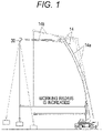
- a crane having a boom has a problem of "cargo swing” indicating that a cargo swings in the horizontal direction due to an increase in a working radius caused by deflection of the boom when the cargo is lifted from the ground, that is, when the cargo is lifted off the ground (see Fig. 1 ).
- a vertical liftoff control device disclosed in Patent Literature 1 is configured to detect the rotation speed of an engine by an engine speed sensor and correct a value of a boom raising operation to a value corresponding to the rotation speed of the engine in order to prevent swing of a cargo when the cargo is lifted off the ground.
- Patent Literature 1 indicates that, with such a configuration, it is possible to perform accurate liftoff control in consideration of a change in rotation speed of the engine.
- Patent Literature 1 JP 8-188379 A
- the conventional liftoff control device is based on the premise that the distal end of the boom is positioned directly above the position of the center of gravity of the cargo, and thus, is difficult to exhibit the effect when the initial position of the distal end of the boom is not located directly above the position of the center of gravity of the cargo.
- an object of the present invention is to provide a control system that can easily bring an initial position of the distal end of a boom close to a position directly above the position of the center of gravity of a cargo using a camera, and a work machine including the control system.
- a control system according to one aspect of the present invention is
- a work machine includes:
- a mobile crane which is an example of a work machine will be described.
- the mobile crane include a rough terrain crane, an allterrain crane, and a truck crane.
- a rough terrain crane will be described below as an example of the mobile crane according to the present embodiment, but a control system according to the present invention can also be applied to other types of mobile cranes.
- the present invention can be applied not only to mobile cranes but also to other types of lifting devices using wire ropes. Therefore, the work machine is not limited to the mobile crane.
- the work machine may indicate various working machines having an arm section including a boom that is freely raised and lowered.
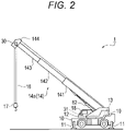
- the mobile crane 1 includes a chassis 10 serving as a main body of a vehicle having a traveling function, outriggers 11 provided at four corners of the chassis 10, a slewing base 12 attached to the chassis 10 so as to be capable of slewing in the horizontal direction, and an arm section 14 (boom 14a) attached to the rear part of the slewing base 12.
- a chassis 10 serving as a main body of a vehicle having a traveling function
- outriggers 11 provided at four corners of the chassis 10
- a slewing base 12 attached to the chassis 10 so as to be capable of slewing in the horizontal direction
- an arm section 14 (boom 14a) attached to the rear part of the slewing base 12.
- Each of the outriggers 11 can be extended outward and retracted from/into the chassis 10 in the width direction in a slidable manner by extending and contracting a slide cylinder, and can be extended and retracted from/into the chassis 10 in the vertical direction by extending and contracting a jack cylinder.
- the slewing base 12 includes a pinion gear to which power of a slewing motor 61 is transmitted.
- the slewing base 12 rotates about a rotation axis with the pinion gear meshing with a circular gear provided on the chassis 10.
- the slewing base 12 includes an operator cab 18 disposed on the right front side and a counterweight 19 disposed on the rear side.
- the operator cab 18 is equipped with a monitor 31 that displays an image captured by a camera 30 (described later).
- a winch 13 for hoisting and lowering a wire rope 16 is disposed on the rear part of the slewing base 12.
- the winch 13 rotates in two directions, which are hoisting direction (take-up direction) and lowering direction (feeding direction), by rotating a winch motor 64 in the forward direction and the reverse direction.
- the boom 14a has a telescopic structure including a base boom 141, (one or a plurality of) intermediate boom(s) 142, and a tip boom 143, and can be extended and retracted by a telescoping cylinder 63 disposed inside the boom 14a.
- the tip boom 143 is provided with a sheave attached to a boom head 144 on the most distal end.
- a wire rope 16 is wound around the sheave, and a hook 17 is hung from the sheave.
- the camera 30 that captures an image of an area below is attached to a side surface (a left side surface in the drawing) of the boom head 144.
- a root portion of the base boom 141 is rotatably attached to a support shaft mounted on the slewing base 12, and can be raised and lowered about the support shaft as a rotation center.
- a derricking cylinder 62 is provided between the slewing base 12 and the lower surface of the base boom 141, and the boom 14a can be entirely raised and lowered by extending and contracting the derricking cylinder 62.
- the mobile crane 1 illustrated in Fig. 2 includes only the boom 14a as the arm section.
- the arm section may include, for example, the boom 14a and a jib 14b supported on the distal end of the boom 14a as illustrated in Figs. 1 and 9A to 9C .
- the distal end of the arm section indicates the distal end of the boom when the mobile crane includes only the boom.
- the distal end of the arm section indicates the distal end of the jib 14b.
- the liftoff control device D mainly includes a controller 40 having functions as an image control unit 401 and a boom control unit 402 as will be described later.
- the controller 40 is a general-purpose microcomputer including an input port, an output port, an arithmetic device, and the like.
- the controller 40 receives operation signals from a slewing lever 51, a derricking lever 52, a telescoping lever 53, and a winch lever 54, which are operation levers, and controls a slewing motor 61, a derricking cylinder 62, a telescoping cylinder 63, and a winch motor 64, which are actuators, via control valves (not illustrated).
- the controller 40 is connected with a liftoff switch 20 for starting/stopping the liftoff control, a winch speed setting unit 21 for setting the speed of the winch 13 during the liftoff control, a load measuring unit 22 for measuring a load acting on the boom 14a, an orientation detecting unit 23 for detecting the orientation of the boom 14a, and a rope length/hoisting speed measuring unit 24 for measuring the rope length of the wire rope 16.
- deflection angle information based on the weight of the boom 14a is stored in advance in a storage device of the controller 40.
- the liftoff switch 20 is an input device for instructing to start or stop the liftoff control.
- the liftoff switch 20 can be added to a safety device of the mobile crane 1, for example, and is preferably disposed in the operator cab 18.
- the winch speed setting unit 21 is an input device that sets the speed of the winch 13 during the liftoff control, and may have a system of selecting an appropriate speed from a preset speed or a system of receiving a speed input via a numeric keypad. Further, similar to the liftoff switch 20, the winch speed setting unit 21 can be added to the safety device of the mobile crane 1, and is preferably disposed in the operator cab 18. Adjusting the speed of the winch 13 by the winch speed setting unit 21 can reduce a time required for the liftoff control.
- the load measuring unit 22 is a measuring instrument that measures a load acting on the boom 14a, and can be, for example, a pressure gauge that measures a pressure acting on the derricking cylinder 62. A pressure signal measured by the pressure gauge is transmitted to the controller 40.
- the orientation detecting unit 23 is a measuring instrument that detects the orientation of the boom 14a, and includes a raising angle meter 231 that measures a raising angle of the boom 14a, a raising angular velocity meter 232 that measures a raising angular velocity, and a boom length meter 233.
- a potentiometer can be used as the raising angle meter 231.
- a stroke sensor attached to the derricking cylinder 62 can be used.
- the boom length meter 233 can be constituted by a wire attached to the boom head 144 and a winding reel.
- a raising angle signal measured by the raising angle meter 231, a raising angular velocity signal measured by the raising angular velocity meter 232, and a boom length signal measured by the boom length meter 233 are transmitted to the controller 40.
- the rope length/hoisting speed measuring unit 24 measures the rope length of the wire rope 16, and can be, for example, a rotation speed meter (so-called rotary encoder) that measures the rotation speed of the winch motor 64.
- the rotation speed meter directly measures the number of rotations of the winch 13, and thus has very good responsiveness.
- the rope length/hoisting speed measuring unit 24 can also detect a temporal change in the rope length, so that the rope length/hoisting speed measuring unit 24 can also be used as a hoisting speed measuring unit.
- the camera 30 corresponds to an example of an image-capturing unit, and is a video camera capable of capturing a moving image in real time.
- the image captured by the camera 30 is displayed in the monitor 31 via the image control unit 401.
- the camera 30 is a so-called active video camera, and is controlled to automatically face downward.
- the camera 30 is equipped with a camera angle meter 25, so that an angle (orientation) of the camera 30 with respect to the boom head 144 (distal end of the arm section) is measured and transmitted to the controller 40.
- the controller 40 corresponds to an example of a control unit, and has a function as the image control unit 401 that controls an image displayed in the monitor 31 as described above.
- the image control unit 401 of the controller 40 causes the monitor 31 to display a cross line serving as a marker M so as to be superimposed on the captured image as illustrated in Fig. 8 .
- the marker M indicates a position directly below the boom head 144 located at the distal end of the boom 14a.
- a laterally extending line L1 of the cross line indicates a position in the front-rear direction (direction in which the telescoping direction of the boom 14a is projected onto the ground surface) directly below the boom head 144 in an imaged region
- a longitudinally extending line L2 of the cross line indicates a position in the horizontal direction (direction orthogonal to the direction in which the telescoping direction of the boom 14a is projected onto the ground surface) directly below the boom head 144 in the imaged region.
- the cross line corresponds to an example of position-related information regarding a position directly below the distal end of the arm section.
- the mode of displaying a cross line as the marker M has been described.
- the display mode of the marker is not limited to the cross line.
- the marker may be displayed in a mode in which, for example, a circle, a quadrangle, a triangle, or the like is displayed at a position directly below the distal end of the boom 14a, or in a mode in which these marks are displayed in combination.
- a predetermined distance for example, 50 cm
- the position of the camera 30 is calculated on the basis of the orientation of the boom 14a, and the coordinate position of the image range displayed in the monitor 31 is specified together with the rotation angle of the camera 30.
- the coordinate position of the distal end of the boom 14a is calculated on the basis of the orientation of the boom 14a. Therefore, the position directly below the distal end of the boom 14a can be indicated within the range of the image in the monitor 31.
- the image control unit 401 of the control system S can accurately estimate and display the true position directly below the distal end of the boom 14a by correcting the image data on the basis of the camera angle (information regarding the angle of the camera) measured by the camera angle meter 25, the boom length (information regarding the length of the arm section) measured by the boom length meter 233, the raising angle (information regarding the raising angle of the arm section) measured by the raising angle meter 231, and deflection angle information (information regarding the deflection angle) of the distal end due to the weight of the boom 14a stored in advance in the controller 40.
- the mobile crane includes the jib 14b
- the information regarding the length of the arm section, the information regarding the raising angle of the arm section, and the information regarding the deflection angle include information regarding the jib 14b.
- the operator when lifting the cargo off the ground, the operator confirms that the position of the boom 14a (that is, the position of the marker M) has moved to a position within a predetermined distance range from the position of the center of gravity of the cargo, and presses a confirmation button (not shown) (that can be added to a safety device), whereby an actual hoisting operation can be started.
- a confirmation button (not shown) (that can be added to a safety device), whereby an actual hoisting operation can be started.
- the position of the hook 17 attached to the cargo may be recognized (assumed) as the position of the center of gravity of the cargo, and the hoisting operation may be automatically started when the center position of the marker M and the position of the hook 17 are within a predetermined distance range (for example, 50 cm or less) (in other words, when a predetermined condition is satisfied).
- a predetermined distance range for example, 50 cm or less
- RFID electronic tag
- the boom 14a, the camera 30, the monitor 31, and the image control unit 401 described above constitute the control system S according to the present embodiment.
- the controller 40 also has a function as the boom control unit 402 that controls the operations of the boom 14a and the winch 13. That is, when the liftoff switch 20 is turned on to lift the cargo by winding up the winch 13, the boom control unit 402 of the controller 40 predicts an amount of change in the raising angle of the boom 14a on the basis of a temporal change in the load measured by the load measuring unit 22, and raises the boom 14a so as to compensate for the predicted amount of change. In this manner, the controller 40 maintains a state in which the position of the center of gravity of the cargo (the position of the hook 17) and the center position of the marker M (the position directly below the distal end of the arm section 14 indicated by the position-related information) satisfy the predetermined condition.
- the controller 40 raises the arm section 14 so that the position of the center of gravity of the cargo (the position of the hook 17) and the center position of the marker M (the position directly below the distal end of the arm section 14 indicated by the position-related information) can be maintained in the state satisfying the predetermined condition.
- the state satisfying the predetermined condition includes a state in which a distance in a horizontal direction between the position of the center of gravity of the cargo (position of the hook 17) and the center position of the marker M (the position directly below the distal end of the arm section 14 indicated by the position-related information) is included within a predetermined distance range.
- the boom control unit 402 includes, as functional units, a selection function unit 40a for selecting a characteristic table or a transfer function, and a liftoff determination function unit 40b that determines whether or not the cargo has been actually lifted off the ground and stops the liftoff control.
- the selection function unit 40a for selecting a characteristic table or a transfer function receives an input of an initial value of the pressure from the load measuring unit 22 (pressure gauge) and an initial value of the raising angle from the raising angle meter 231 serving as the orientation detecting unit 23, and determines the characteristic table or transfer function to be applied.
- a relationship using a linear coefficient a can be applied as follows.
- a is a constant (linear coefficient).
- a temporal change (differential) of the load is used as an input.
- the liftoff determination function unit 40b monitors time-series data of the value of the load calculated from the pressure signal from the load measuring unit 22 (pressure gauge), and determines whether or not the cargo is lifted off the ground. A method for determining the liftoff will be described later with reference to Figs. 9A to 9C .
- a load change calculation unit 71 calculates a load change on the basis of time-series data of the load measured by the load measuring unit 22.
- the calculated load change is input to a target shaft speed calculation unit 72.
- the input/output relationship for the target shaft speed calculation unit 72 will be described later with reference to Fig. 6 .
- the target shaft speed calculation unit 72 calculates a target shaft speed on the basis of the initial value of the raising angle, the set winch speed, and the input load change.
- the target shaft speed is a target raising angular velocity (and, although not required, a target winch speed).
- the calculated target shaft speed is input to the shaft speed controller 73.
- the first half control described above indicates processing related to the liftoff control according to the present embodiment.
- an operation amount is input to a control target 75 via the shaft speed controller 73 and a shaft-speed operation amount conversion processing unit 74.
- the second half control described above indicates processing related to normal control, and feedback control is performed on the basis of the measured raising angular velocity.
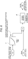
- an input/output relationship of elements in the target shaft speed calculation unit 72 during the liftoff control will be particularly described with reference to a block diagram of Fig. 6 .
- an initial value of the raising angle is input to a selection function unit 81 (40a) for selecting characteristic table/transfer function.
- the selection function unit 81 the most appropriate constant (linear coefficient) a is selected using a characteristic table (lookup table) or a transfer function.
- the target raising angular velocity is calculated by multiplying the result of the numerical differentiation by the constant a. That is, the target raising angular velocity is calculated by executing the calculation of (Mathematical formula 3) described above. As described above, the target raising angular velocity is obtained by feedforward control using the characteristic table (or the transfer function).
- the operator presses the liftoff switch 20 to start the liftoff control (START).
- the liftoff switch 20 starts the liftoff control (START).
- the camera 30 is provided at the distal end of the jib 14b.
- the following description can also be applied, as appropriate, to a case where the mobile crane 1 includes only the boom 14a as the arm section 14.
- an image captured by the camera 30 is displayed in the monitor 31 in the operator cab 18, and as illustrated in Fig. 8 , a cross line which is the marker M indicating the position directly below the distal end of the arm section 14 (jib 14b) is displayed so as to be superimposed on the captured image.
- the operator While viewing the image in the monitor 31, the operator adjusts the position of the arm section 14 (jib 14b) so that the position of the distal end of the arm section 14 (jib 14b) approaches the position of the center of gravity of the cargo (which may be regarded as substantially the position of the hook 17) (step S0).
- the operator confirms that the position of the arm section 14 (jib 14b) (that is, the position of the marker M) has moved to a position within a predetermined distance range from the position of the center of gravity of the cargo, and presses the confirmation button (not shown), whereby an actual hoisting operation is started.
- the controller 40 automatically starts the hoisting operation (step S0).
- a target speed of the winch 13 is set in advance using the winch speed setting unit 21 before or after the start of the liftoff control. Then, the controller 40 starts winch control at the target speed (step S1).
- the measurement of the load of the cargo is started by the load measuring unit 22, and a load value is input to the controller 40 (step S2).
- the selection function unit 40a determines a characteristic table or a transfer function to be applied in response to the input of the initial value of the load and the initial value of the raising angle from the raising angle meter 231 serving as the orientation detecting unit 23 (step S3).
- the controller 40 calculates a raising angular velocity on the basis of the applied characteristic table or transfer function and the load change (step S4). That is, the raising angular velocity control is performed by feedforward control.
- step S5 whether or not the cargo is lifted off the ground is determined on the basis of the time-series data of the measured load. The determination method will be described later.
- the process returns to step S2, and the feedforward control based on the load is repeated (steps S2 to S5).
- step S5 When the cargo is lifted off the ground as a result of the determination (YES in step S5), the liftoff control is gradually stopped (step S6). That is, the rotational driving of the winch 13 by the winch motor is stopped while reducing the speed, and the derricking driving by the derricking cylinder 62 is stopped while reducing the speed.
- the liftoff determination device C includes the arm section 14 (boom 14a and jib 14b), the winch 13, the load measuring unit 22, the rope length/hoisting speed measuring unit 24, and the controller 40 serving as a control unit that controls the arm section 14 (boom 14a and jib 14b) and the winch 13.
- the controller 40 in the present embodiment determines liftoff on the basis of a temporal change in the measured load and a temporal change in the measured rope length when lifting the cargo by winding up the winch 13.
- the controller 40 serving as the control unit sets the rope length at a timing at which the measured load starts to change as an initial rope length, and determines that the cargo is lifted off the ground when the rope length is shorter than a set threshold from the initial rope length.
- the controller 40 serving as the control unit sets the temporal change in the rope length at a timing at which the measured load starts to change as an initial hoisting speed, and determines that the cargo is lifted off the ground when the hoisting speed indicating the temporal change in the rope length is higher than a set threshold from the initial hoisting speed.
- the temporal change in the rope length that is, the hoisting speed is initialized. Thereafter, when the winch 13 is further wound up, the hoisting speed is suddenly increased after the arm section 14 (boom 14a) deflects maximally as illustrated in Fig. 9C .
- the time point at which the hoisting speed has suddenly changed in this way can be obtained and determined as a liftoff time.
- the liftoff determination method includes a step of winding up the winch 13, a step of measuring a load, a step of measuring a rope length of the wire rope 16, a step of storing the rope length at a timing at which the load starts to change as an initial rope length, and a step of determining that the cargo is lifted off the ground when the rope length is shorter than a set threshold from the initial rope length.
- the liftoff determination method includes a step of winding up the winch 13, a step of measuring a load, a step of measuring a hoisting speed of the wire rope 16, a step of storing the hoisting speed at a timing at which the load starts to change as an initial hoisting speed, and a step of determining that the cargo is lifted off the ground when the hoisting speed is higher than a set threshold from the initial hoisting speed.
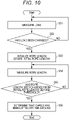
- the liftoff determination method will be described below with reference to a flowchart of Fig. 10 .
- the liftoff determination method will be described with reference to the flowchart of Fig. 10 .
- the overview of the liftoff control method is as described with reference to Fig. 7 . That is, the process of the liftoff determination in step S5 in the flowchart of Fig. 7 will be described here.
- the liftoff determination method is divided into a first half part for obtaining a change in the load (steps S51 and S52) and a second half part for obtaining a change in the rope length (or hoisting speed) (steps S53 to S55).
- the following description is given based on the premise that the load is measured in step S51 for convenience of description.
- a load is first measured by the load measuring unit 22, and time-series data of the load is monitored by the controller 40 (step S51).
- the controller 40 initializes the rope length (step S53). That is, a rope length R0 at the time at which the rope length exceeds the threshold is stored.
- the controller 40 continues the measurement of the load (steps S51 and S52).
- the rope length is first measured by the rope length/hoisting speed measuring unit 24, and time-series data of the rope length is monitored by the controller 40 (step S54).
- the controller 40 determines that the cargo is lifted off the ground (step S56).
- the controller 40 continues the measurement of the rope length (steps S54 and S55).
- the controller 40 determines that the cargo is lifted off the ground (corresponding to step S56). On the other hand, when the hoisting speed is not higher than the threshold from the initial hoisting speed V0 (corresponding to NO in step S55), the controller 40 continues the measurement of the rope length (hoisting speed) (corresponding to steps S54 and S55).
- step S51 and S52 determine whether or not the cargo is lifted off the ground.
- the control system S includes: the arm section 14 (boom 14a and jib 14b) that is freely raised and lowered; the camera 30 that is provided at the distal end of the arm section 14 (jib 14b) and captures an image of an area below; the monitor 31 that displays the captured image; and the image control unit 401 that controls the image displayed in the monitor 31.
- the image control unit 401 causes the monitor 31 to display the marker M indicating the position directly below the distal end of the arm section 14 (jib 14b) so as to be superimposed on the image.
- the operator adjusts the position of the arm section 14 (boom 14a and jib 14b) while viewing the position of the marker M displayed in the monitor 31 in real time, thereby being capable of easily moving the initial position of the distal end of the arm section 14 (jib 14b) to the position almost directly above the cargo.
- This configuration is significantly effective particularly in a case where, for example, the operator cannot see the area around the cargo from the operator cab 18 due to an obstacle or the like being present.
- the control system S is applied to the feedforward control, whereby it is possible to prevent swing of the cargo caused by the displacement of the initial position.
- control system S further includes the boom control unit 402 that controls the operation of the arm section 14 (boom 14a), and the boom control unit 402 starts a liftoff operation for the arm section 14 (boom 14a and jib 14b) when the marker M moves to a position within a predetermined distance range from the position of the center of gravity of the cargo at the time of lifting the cargo off the ground.
- the operator performs the liftoff operation after recognizing the initial position of the distal end of the arm section 14 (jib 14b), so that it is easy to prevent the displacement of the initial position of the distal end of the arm section 14 (jib 14b).
- control system S further includes the hook 17 that is suspended from the distal end of the arm section 14 (jib 14b) via the wire rope 16, and the boom control unit 402 recognizes the position of the hook 17 as the position of the center of gravity of the cargo.
- the position of the hook 17 can be recognized by image recognition, or with an electronic tag, or the like, so that the initial position of the distal end of the arm section 14 (jib 14b) can be fully automatically adjusted.
- control system S further includes the load measuring unit 22 that measures a load acting on the arm section 14 (boom 14a), and the boom control unit 402 obtains an amount of change of the raising angle of the arm section 14 (boom 14a) on the basis of a temporal change in the measured load, and raises the arm section 14 (boom 14a) to compensate for the amount of change when lifting the cargo off the ground. Due to the configuration in which the control system S is applied to the feedforward control, it is possible to prevent the swing of the cargo caused by the displacement of the initial position.
- the control system S further includes the camera angle meter 25 that measures an angle of the camera 30 with respect to the arm section 14 (jib 14b), the boom length meter 233 that measures the length of the arm section 14 (boom 14a and/or jib 14b), and the raising angle meter 231 that measures a raising angle of the arm section 14 (boom 14a and/or jib 14b), and the image control unit 401 estimates a position directly below the distal end of the arm section 14 (boom 14a and/or jib 14b) on the basis of the measured camera angle, the measured boom length, the measured raising angle, and deflection angle information due to the weight of the arm section 14 (boom 14a and/or jib 14b) stored in advance.
- the position directly below the distal end of the arm section (boom 14a and/or jib 14b) can be accurately estimated and displayed in the monitor 31.
- the angle of the camera 30 is likely to vary because the camera 30 is attached to the distal end of the long arm section 14 (boom 14a and/or jib 14b).
- the above configuration is applied, whereby the position directly below the distal end of the arm section 14 (boom 14a and/or jib 14b) can be estimated with high accuracy while following a variation in angle of the camera 30 in real time.
- the liftoff determination device C includes: the arm section 14 that is freely raised and lowered; the winch 13 that hoists/lowers the cargo via the wire rope 16; the load measuring unit 22 that measures a load acting on the arm section 14; the rope length/hoisting speed measuring unit 24 that measure a rope length of the wire rope 16; and the controller 40 that controls the arm section 14 and the winch 13, wherein the controller 40 determines liftoff on the basis of a temporal change in the measured load and a temporal change in the measured rope length when lifting the cargo off the ground by winding up the winch 13.
- the liftoff determination device C can be configured to have good responsiveness with a simple configuration. Furthermore, the liftoff determination device C can also be used to set coordinates for route control on the basis of the relationship between the rope length and the lifting height of the cargo.
- the controller 40 sets the rope length at a timing at which the measured load starts to change as an initial rope length R0, and determines that the cargo is lifted off the ground when the rope length is shorter than a set threshold from the initial rope length R0.
- the controller 40 sets the temporal change in the rope length at a timing at which the measured load starts to change as an initial hoisting speed V0, and determines that the cargo is lifted off the ground when the hoisting speed indicating the temporal change in the rope length is higher than a set threshold from the initial hoisting speed V0.
- the liftoff control device D includes the arm section 14 (boom 14a), the winch 13, the load measuring unit 22, and the controller 40 serving as the control unit that controls the arm section 14 and the winch 13, the controller 40 obtaining an amount of change of the raising angle of the arm section 14 (boom 14a) on the basis of a temporal change in the measured load and raising and lowering the arm section (boom 14a) to compensate for the amount of change when lifting the cargo off the ground by winding up the winch 13.
- the liftoff control device D can quickly lift the cargo off the ground while suppressing swing of the cargo.
- the liftoff control device D performs feedforward control on the basis of only a temporal change in the load value, thereby being capable of quickly lifting the cargo off the ground without performing complicated feedback control that is conventionally performed.
- the liftoff control device D further includes the orientation detecting unit 23 that measures the orientation of the arm section 14 (boom 14a), and the controller 40 selects a corresponding characteristic table or transfer function on the basis of an initial value of the measured orientation of the arm section 14 (boom 14a) and an initial value of the measured load, and obtains an amount of change of the raising angle of the arm section 14 (boom 14a) from a temporal change in the measured load using the characteristic table or transfer function.
- the winch 13 is wound up at a constant speed, and a raising angle control amount is calculated from the characteristic table (or the transfer function) in accordance with the load change to perform the feedforward control, so that the cargo can be quickly lifted off the ground without swinging.
- the number of parameters to be adjusted is reduced, whereby adjustment at the time of shipment can be quickly and easily performed.
- the controller 40 winds up the winch 13 at a constant speed when lifting the cargo off the ground by winding up the winch 13.
- the response is stabilized by suppressing an influence of disturbances such as inertial force, and thus, whether or not the cargo is lifted off the ground can be easily determined.
- the mobile crane 1 includes any one of the control system S, the liftoff determination device C, and the liftoff control device D described above, so that the mobile crane 1 is capable of quickly lifting the cargo off the ground while suppressing swing of the cargo caused by the displacement of an initial position.
- the liftoff determination method includes a step of winding up the winch 13, a step of measuring a load, a step of measuring a rope length of the wire rope 16, a step of storing the rope length at a timing at which the load starts to change as an initial rope length R0, and a step of determining that the cargo is lifted off the ground when the rope length is shorter than a set threshold from the initial rope length R0.
- another liftoff determination method includes a step of winding up the winch 13, a step of measuring a load, a step of measuring a hoisting speed of the wire rope 16, a step of storing the hoisting speed at a timing at which the load starts to change as an initial hoisting speed V0, and a step of determining that the cargo is lifted off the ground when the hoisting speed is higher than a set threshold from the initial hoisting speed V0.
- control system S and the liftoff control device D according to the present invention can also be applied to a case where a cargo is lifted off the ground using a main winch as the winch 13 and a case where the cargo is lifted off the ground using a sub winch as the winch 13.
- control system S is applied to feedforward control
- the configuration is not limited thereto, and it is obvious that the control system S according to the present embodiment can also be applied to a conventional liftoff method.
- the present invention can be applied to various work machines including an arm section that is freely raised and lowered.
Landscapes
- Engineering & Computer Science (AREA)
- Mechanical Engineering (AREA)
- Automation & Control Theory (AREA)
- Jib Cranes (AREA)
- Control And Safety Of Cranes (AREA)
Abstract
Description
- The present invention relates to a control system and a work machine.
- Conventionally, a crane having a boom has a problem of "cargo swing" indicating that a cargo swings in the horizontal direction due to an increase in a working radius caused by deflection of the boom when the cargo is lifted from the ground, that is, when the cargo is lifted off the ground (see
Fig. 1 ). - A vertical liftoff control device disclosed in
Patent Literature 1 is configured to detect the rotation speed of an engine by an engine speed sensor and correct a value of a boom raising operation to a value corresponding to the rotation speed of the engine in order to prevent swing of a cargo when the cargo is lifted off the ground.Patent Literature 1 indicates that, with such a configuration, it is possible to perform accurate liftoff control in consideration of a change in rotation speed of the engine. - However, conventional liftoff control devices including the liftoff control device disclosed in
Patent Literature 1 perform control using two actuators (winch and derricking cylinder) in combination so as to keep the working radius constant by hoisting an extended amount of wire with a winch and raising a boom. - Patent Literature 1:
JP 8-188379 A - However, the conventional liftoff control device is based on the premise that the distal end of the boom is positioned directly above the position of the center of gravity of the cargo, and thus, is difficult to exhibit the effect when the initial position of the distal end of the boom is not located directly above the position of the center of gravity of the cargo.
- In view of this, an object of the present invention is to provide a control system that can easily bring an initial position of the distal end of a boom close to a position directly above the position of the center of gravity of a cargo using a camera, and a work machine including the control system.
- A control system according to one aspect of the present invention is
- incorporated in a work machine having an arm section including a boom that is freely raised and lowered, the control system including:
- an image-capturing unit that is provided at a distal end of the arm section and captures an image of an area below;
- a display unit that displays an image captured by the image-capturing unit; and
- a control unit that causes the display unit to display position-related information regarding a position directly below the distal end of the arm section so as to be superimposed on the image.
- A work machine according to one aspect of the present invention includes:
- an arm section including a boom that is freely raised and lowered; and
- the control system described above.
- According to the present invention, it is possible to provide a control system and a work machine that allow an operator to easily bring an initial position of a distal end of a boom close to a position directly above the position of the center of gravity of a cargo.
-
-
Fig. 1 is an explanatory view for describing swing of a cargo. -
Fig. 2 is a side view of a mobile crane. -
Fig. 3 is a block diagram of a liftoff control device. -
Fig. 4 is a graph illustrating a relationship between a load and a raising angle. -
Fig. 5 is a block diagram entirely illustrating the liftoff control device. -
Fig. 6 is a block diagram illustrating liftoff control. -
Fig. 7 is a flowchart of the liftoff control. -
Fig. 8 is a monitor image that displays a marker superimposed on a captured image. -
Fig. 9A is a graph for describing a concept of liftoff determination. -
Fig. 9B is a graph for describing the concept of liftoff determination. -
Fig. 9C is a graph for describing the concept of liftoff determination. -
Fig. 10 is a flowchart illustrating a liftoff determination method. - Embodiments of the present invention will now be described with reference to the accompanying drawings. It is to be noted that the components described in the following embodiments are merely examples, and the technical scope of the present invention is not limited thereto.
- In the present embodiment, a mobile crane which is an example of a work machine will be described. Examples of the mobile crane include a rough terrain crane, an allterrain crane, and a truck crane. A rough terrain crane will be described below as an example of the mobile crane according to the present embodiment, but a control system according to the present invention can also be applied to other types of mobile cranes. In addition, the present invention can be applied not only to mobile cranes but also to other types of lifting devices using wire ropes. Therefore, the work machine is not limited to the mobile crane. The work machine may indicate various working machines having an arm section including a boom that is freely raised and lowered.
- First, a configuration of a mobile crane will be described with reference to a side view of
Fig. 2 . As illustrated inFig. 2 , themobile crane 1 according to the present embodiment includes achassis 10 serving as a main body of a vehicle having a traveling function,outriggers 11 provided at four corners of thechassis 10, aslewing base 12 attached to thechassis 10 so as to be capable of slewing in the horizontal direction, and an arm section 14 (boom 14a) attached to the rear part of theslewing base 12. - Each of the
outriggers 11 can be extended outward and retracted from/into thechassis 10 in the width direction in a slidable manner by extending and contracting a slide cylinder, and can be extended and retracted from/into thechassis 10 in the vertical direction by extending and contracting a jack cylinder. - The
slewing base 12 includes a pinion gear to which power of aslewing motor 61 is transmitted. Theslewing base 12 rotates about a rotation axis with the pinion gear meshing with a circular gear provided on thechassis 10. Theslewing base 12 includes an operator cab 18 disposed on the right front side and acounterweight 19 disposed on the rear side. The operator cab 18 is equipped with amonitor 31 that displays an image captured by a camera 30 (described later). - Furthermore, a
winch 13 for hoisting and lowering awire rope 16 is disposed on the rear part of theslewing base 12. Thewinch 13 rotates in two directions, which are hoisting direction (take-up direction) and lowering direction (feeding direction), by rotating awinch motor 64 in the forward direction and the reverse direction. - The
boom 14a has a telescopic structure including abase boom 141, (one or a plurality of) intermediate boom(s) 142, and atip boom 143, and can be extended and retracted by a telescopingcylinder 63 disposed inside theboom 14a. Thetip boom 143 is provided with a sheave attached to aboom head 144 on the most distal end. Awire rope 16 is wound around the sheave, and ahook 17 is hung from the sheave. As described later, thecamera 30 that captures an image of an area below is attached to a side surface (a left side surface in the drawing) of theboom head 144. - A root portion of the
base boom 141 is rotatably attached to a support shaft mounted on theslewing base 12, and can be raised and lowered about the support shaft as a rotation center. A derrickingcylinder 62 is provided between theslewing base 12 and the lower surface of thebase boom 141, and theboom 14a can be entirely raised and lowered by extending and contracting the derrickingcylinder 62. - Note that the
mobile crane 1 illustrated inFig. 2 includes only theboom 14a as the arm section. However, the arm section may include, for example, theboom 14a and ajib 14b supported on the distal end of theboom 14a as illustrated inFigs. 1 and9A to 9C . The distal end of the arm section indicates the distal end of the boom when the mobile crane includes only the boom. On the other hand, when the mobile crane includes theboom 14a and thejib 14b, the distal end of the arm section indicates the distal end of thejib 14b. - Next, a configuration of a control system of a liftoff control device D including the control system S according to the present embodiment will be described with reference to a block diagram of
Fig. 3 . The liftoff control device D mainly includes acontroller 40 having functions as animage control unit 401 and aboom control unit 402 as will be described later. Thecontroller 40 is a general-purpose microcomputer including an input port, an output port, an arithmetic device, and the like. Thecontroller 40 receives operation signals from a slewing lever 51, a derricking lever 52, atelescoping lever 53, and a winch lever 54, which are operation levers, and controls a slewingmotor 61, aderricking cylinder 62, atelescoping cylinder 63, and awinch motor 64, which are actuators, via control valves (not illustrated). - Furthermore, the
controller 40 according to the present embodiment is connected with aliftoff switch 20 for starting/stopping the liftoff control, a winch speed setting unit 21 for setting the speed of thewinch 13 during the liftoff control, aload measuring unit 22 for measuring a load acting on theboom 14a, an orientation detecting unit 23 for detecting the orientation of theboom 14a, and a rope length/hoistingspeed measuring unit 24 for measuring the rope length of thewire rope 16. In addition, deflection angle information based on the weight of theboom 14a is stored in advance in a storage device of thecontroller 40. - The
liftoff switch 20 is an input device for instructing to start or stop the liftoff control. Theliftoff switch 20 can be added to a safety device of themobile crane 1, for example, and is preferably disposed in the operator cab 18. - The winch speed setting unit 21 is an input device that sets the speed of the
winch 13 during the liftoff control, and may have a system of selecting an appropriate speed from a preset speed or a system of receiving a speed input via a numeric keypad. Further, similar to theliftoff switch 20, the winch speed setting unit 21 can be added to the safety device of themobile crane 1, and is preferably disposed in the operator cab 18. Adjusting the speed of thewinch 13 by the winch speed setting unit 21 can reduce a time required for the liftoff control. - The
load measuring unit 22 is a measuring instrument that measures a load acting on theboom 14a, and can be, for example, a pressure gauge that measures a pressure acting on thederricking cylinder 62. A pressure signal measured by the pressure gauge is transmitted to thecontroller 40. - The orientation detecting unit 23 is a measuring instrument that detects the orientation of the
boom 14a, and includes a raising angle meter 231 that measures a raising angle of theboom 14a, a raising angular velocity meter 232 that measures a raising angular velocity, and a boom length meter 233. Specifically, a potentiometer can be used as the raising angle meter 231. As the raising angular velocity meter 232, a stroke sensor attached to thederricking cylinder 62 can be used. In addition, the boom length meter 233 can be constituted by a wire attached to theboom head 144 and a winding reel. A raising angle signal measured by the raising angle meter 231, a raising angular velocity signal measured by the raising angular velocity meter 232, and a boom length signal measured by the boom length meter 233 are transmitted to thecontroller 40. - The rope length/hoisting
speed measuring unit 24 measures the rope length of thewire rope 16, and can be, for example, a rotation speed meter (so-called rotary encoder) that measures the rotation speed of thewinch motor 64. The rotation speed meter directly measures the number of rotations of thewinch 13, and thus has very good responsiveness. Obviously, the rope length/hoistingspeed measuring unit 24 can also detect a temporal change in the rope length, so that the rope length/hoistingspeed measuring unit 24 can also be used as a hoisting speed measuring unit. - The
camera 30 corresponds to an example of an image-capturing unit, and is a video camera capable of capturing a moving image in real time. The image captured by thecamera 30 is displayed in themonitor 31 via theimage control unit 401. Thecamera 30 is a so-called active video camera, and is controlled to automatically face downward. Thecamera 30 is equipped with a camera angle meter 25, so that an angle (orientation) of thecamera 30 with respect to the boom head 144 (distal end of the arm section) is measured and transmitted to thecontroller 40. - The
controller 40 corresponds to an example of a control unit, and has a function as theimage control unit 401 that controls an image displayed in themonitor 31 as described above. Theimage control unit 401 of thecontroller 40 causes themonitor 31 to display a cross line serving as a marker M so as to be superimposed on the captured image as illustrated inFig. 8 . The marker M indicates a position directly below theboom head 144 located at the distal end of theboom 14a. That is, a laterally extending line L1 of the cross line indicates a position in the front-rear direction (direction in which the telescoping direction of theboom 14a is projected onto the ground surface) directly below theboom head 144 in an imaged region, and a longitudinally extending line L2 of the cross line indicates a position in the horizontal direction (direction orthogonal to the direction in which the telescoping direction of theboom 14a is projected onto the ground surface) directly below theboom head 144 in the imaged region. In the present embodiment, the cross line corresponds to an example of position-related information regarding a position directly below the distal end of the arm section. - Here, the mode of displaying a cross line as the marker M has been described. However, the display mode of the marker is not limited to the cross line. The marker may be displayed in a mode in which, for example, a circle, a quadrangle, a triangle, or the like is displayed at a position directly below the distal end of the
boom 14a, or in a mode in which these marks are displayed in combination. Furthermore, it is also possible to display a circle separated from the marker M (that is, the position of the distal end of theboom 14a) by a predetermined distance (for example, 50 cm). In other words, the position-related information regarding the position directly below the distal end of the arm section is not limited to the cross line. - In the image captured by the
camera 30, the position of thecamera 30 is calculated on the basis of the orientation of theboom 14a, and the coordinate position of the image range displayed in themonitor 31 is specified together with the rotation angle of thecamera 30. Separately, the coordinate position of the distal end of theboom 14a is calculated on the basis of the orientation of theboom 14a. Therefore, the position directly below the distal end of theboom 14a can be indicated within the range of the image in themonitor 31. - There is a problem, unique to a mobile crane, that the angle of the
camera 30 is likely to vary because thecamera 30 is attached to the distal end of thelong boom 14a. In view of this, theimage control unit 401 of the control system S according to the present embodiment can accurately estimate and display the true position directly below the distal end of theboom 14a by correcting the image data on the basis of the camera angle (information regarding the angle of the camera) measured by the camera angle meter 25, the boom length (information regarding the length of the arm section) measured by the boom length meter 233, the raising angle (information regarding the raising angle of the arm section) measured by the raising angle meter 231, and deflection angle information (information regarding the deflection angle) of the distal end due to the weight of theboom 14a stored in advance in thecontroller 40. When the mobile crane includes thejib 14b, the information regarding the length of the arm section, the information regarding the raising angle of the arm section, and the information regarding the deflection angle include information regarding thejib 14b. - As will be described later, when lifting the cargo off the ground, the operator confirms that the position of the
boom 14a (that is, the position of the marker M) has moved to a position within a predetermined distance range from the position of the center of gravity of the cargo, and presses a confirmation button (not shown) (that can be added to a safety device), whereby an actual hoisting operation can be started. - As another method, the position of the
hook 17 attached to the cargo may be recognized (assumed) as the position of the center of gravity of the cargo, and the hoisting operation may be automatically started when the center position of the marker M and the position of thehook 17 are within a predetermined distance range (for example, 50 cm or less) (in other words, when a predetermined condition is satisfied). In this case, it is also preferable to mount an electronic tag (RFID) or the like on thehook 17 in order to automatically recognize the position of thehook 17. - The
boom 14a, thecamera 30, themonitor 31, and theimage control unit 401 described above constitute the control system S according to the present embodiment. - On the other hand, as described above, the
controller 40 also has a function as theboom control unit 402 that controls the operations of theboom 14a and thewinch 13. That is, when theliftoff switch 20 is turned on to lift the cargo by winding up thewinch 13, theboom control unit 402 of thecontroller 40 predicts an amount of change in the raising angle of theboom 14a on the basis of a temporal change in the load measured by theload measuring unit 22, and raises theboom 14a so as to compensate for the predicted amount of change. In this manner, thecontroller 40 maintains a state in which the position of the center of gravity of the cargo (the position of the hook 17) and the center position of the marker M (the position directly below the distal end of thearm section 14 indicated by the position-related information) satisfy the predetermined condition. - In other words, when lifting the cargo, the
controller 40 raises thearm section 14 so that the position of the center of gravity of the cargo (the position of the hook 17) and the center position of the marker M (the position directly below the distal end of thearm section 14 indicated by the position-related information) can be maintained in the state satisfying the predetermined condition. The state satisfying the predetermined condition includes a state in which a distance in a horizontal direction between the position of the center of gravity of the cargo (position of the hook 17) and the center position of the marker M (the position directly below the distal end of thearm section 14 indicated by the position-related information) is included within a predetermined distance range. - More specifically, the
boom control unit 402 includes, as functional units, aselection function unit 40a for selecting a characteristic table or a transfer function, and a liftoffdetermination function unit 40b that determines whether or not the cargo has been actually lifted off the ground and stops the liftoff control. - The
selection function unit 40a for selecting a characteristic table or a transfer function receives an input of an initial value of the pressure from the load measuring unit 22 (pressure gauge) and an initial value of the raising angle from the raising angle meter 231 serving as the orientation detecting unit 23, and determines the characteristic table or transfer function to be applied. Here, as the transfer function, a relationship using a linear coefficient a can be applied as follows. - First, as shown in a load-raising angle graph of
Fig. 4 , it is found that the load and the raising angle (angle of the distal end to the ground) have a linear relationship when the position of the distal end of the boom is adjusted so as to be always positioned directly above the cargo in order to prevent the swing of the cargo. Assuming that a load Load1 changes to Load2 between a time t1 and a time t2 during the liftoff,Mathematical formula 1 is established.
- The difference equation is obtained from the difference between the two formulas.
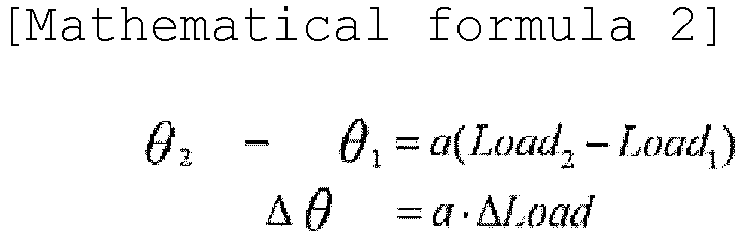
- In order to control the raising angle, it is necessary to give a raising angular velocity.
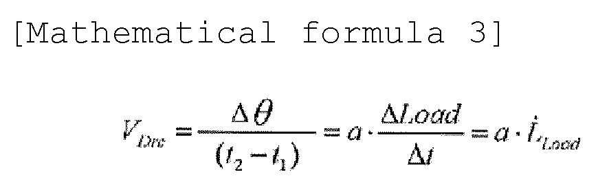
- Here, a is a constant (linear coefficient).
- That is, in the raising angle control, a temporal change (differential) of the load is used as an input.
- The liftoff
determination function unit 40b monitors time-series data of the value of the load calculated from the pressure signal from the load measuring unit 22 (pressure gauge), and determines whether or not the cargo is lifted off the ground. A method for determining the liftoff will be described later with reference toFigs. 9A to 9C . - Next, an input/output relationship among all elements including the liftoff control of the present embodiment will be described in detail with reference to a block diagram of
Fig. 5 . First, a loadchange calculation unit 71 calculates a load change on the basis of time-series data of the load measured by theload measuring unit 22. The calculated load change is input to a target shaftspeed calculation unit 72. The input/output relationship for the target shaftspeed calculation unit 72 will be described later with reference toFig. 6 . - The target shaft
speed calculation unit 72 calculates a target shaft speed on the basis of the initial value of the raising angle, the set winch speed, and the input load change. Here, the target shaft speed is a target raising angular velocity (and, although not required, a target winch speed). The calculated target shaft speed is input to theshaft speed controller 73. The first half control described above indicates processing related to the liftoff control according to the present embodiment. - Thereafter, an operation amount is input to a
control target 75 via theshaft speed controller 73 and a shaft-speed operation amountconversion processing unit 74. The second half control described above indicates processing related to normal control, and feedback control is performed on the basis of the measured raising angular velocity. - Next, an input/output relationship of elements in the target shaft
speed calculation unit 72 during the liftoff control will be particularly described with reference to a block diagram ofFig. 6 . First, an initial value of the raising angle is input to a selection function unit 81 (40a) for selecting characteristic table/transfer function. In theselection function unit 81, the most appropriate constant (linear coefficient) a is selected using a characteristic table (lookup table) or a transfer function. - Then, numerical differentiation (differentiation with respect to time) of the load change is performed in a
numerical differentiation unit 82, and the target raising angular velocity is calculated by multiplying the result of the numerical differentiation by the constant a. That is, the target raising angular velocity is calculated by executing the calculation of (Mathematical formula 3) described above. As described above, the target raising angular velocity is obtained by feedforward control using the characteristic table (or the transfer function). - Next, the overall flow of the liftoff control of the present embodiment will be described with reference to the flowchart of
Fig. 7 . - First, the operator presses the
liftoff switch 20 to start the liftoff control (START). Note that, in the following, a case where thearm section 14 includes theboom 14a and thejib 14b as in themobile crane 1 illustrated inFigs. 9A to 9C will be described. Therefore, thecamera 30 is provided at the distal end of thejib 14b. The following description can also be applied, as appropriate, to a case where themobile crane 1 includes only theboom 14a as thearm section 14. - Then, an image captured by the
camera 30 is displayed in themonitor 31 in the operator cab 18, and as illustrated inFig. 8 , a cross line which is the marker M indicating the position directly below the distal end of the arm section 14 (jib 14b) is displayed so as to be superimposed on the captured image. While viewing the image in themonitor 31, the operator adjusts the position of the arm section 14 (jib 14b) so that the position of the distal end of the arm section 14 (jib 14b) approaches the position of the center of gravity of the cargo (which may be regarded as substantially the position of the hook 17) (step S0). - Then, the operator confirms that the position of the arm section 14 (
jib 14b) (that is, the position of the marker M) has moved to a position within a predetermined distance range from the position of the center of gravity of the cargo, and presses the confirmation button (not shown), whereby an actual hoisting operation is started. Alternatively, when the distance between the position of the hook 17 (regarded as the position of the center of gravity of the cargo) and the center position of the marker M is equal to or less than a predetermined distance, thecontroller 40 automatically starts the hoisting operation (step S0). - At this time, a target speed of the
winch 13 is set in advance using the winch speed setting unit 21 before or after the start of the liftoff control. Then, thecontroller 40 starts winch control at the target speed (step S1). - Next, at the same time as the
winch 13 is wound up, the measurement of the load of the cargo is started by theload measuring unit 22, and a load value is input to the controller 40 (step S2). Then, theselection function unit 40a determines a characteristic table or a transfer function to be applied in response to the input of the initial value of the load and the initial value of the raising angle from the raising angle meter 231 serving as the orientation detecting unit 23 (step S3). - Next, the
controller 40 calculates a raising angular velocity on the basis of the applied characteristic table or transfer function and the load change (step S4). That is, the raising angular velocity control is performed by feedforward control. - Then, whether or not the cargo is lifted off the ground is determined on the basis of the time-series data of the measured load (step S5). The determination method will be described later. When the cargo is not yet lifted off the ground as a result of the determination (NO in step S5), the process returns to step S2, and the feedforward control based on the load is repeated (steps S2 to S5).
- When the cargo is lifted off the ground as a result of the determination (YES in step S5), the liftoff control is gradually stopped (step S6). That is, the rotational driving of the
winch 13 by the winch motor is stopped while reducing the speed, and the derricking driving by thederricking cylinder 62 is stopped while reducing the speed. - Next, a liftoff determination device C and a liftoff determination method according to the present embodiment will be described in detail with reference to
Figs. 9A to 9C and10 . The liftoff determination device C includes the arm section 14 (boom 14a andjib 14b), thewinch 13, theload measuring unit 22, the rope length/hoistingspeed measuring unit 24, and thecontroller 40 serving as a control unit that controls the arm section 14 (boom 14a andjib 14b) and thewinch 13. - During the liftoff control, the
controller 40 in the present embodiment determines liftoff on the basis of a temporal change in the measured load and a temporal change in the measured rope length when lifting the cargo by winding up thewinch 13. - Specifically, when lifting the cargo by winding up the
winch 13, thecontroller 40 serving as the control unit sets the rope length at a timing at which the measured load starts to change as an initial rope length, and determines that the cargo is lifted off the ground when the rope length is shorter than a set threshold from the initial rope length. - Alternatively, when lifting the cargo by winding up the
winch 13, thecontroller 40 serving as the control unit sets the temporal change in the rope length at a timing at which the measured load starts to change as an initial hoisting speed, and determines that the cargo is lifted off the ground when the hoisting speed indicating the temporal change in the rope length is higher than a set threshold from the initial hoisting speed. - That is, as illustrated in
Fig. 9A , at the start of liftoff, when thewinch 13 is wound up, almost no load is exerted, because thewire rope 16 is slackened. Therefore, when the winch is continuously wound up, the weights of thewire rope 16 and thehook 17 are exerted. When thewinch 13 is further wound up, the load increases (changes) while bending the arm section 14 (boom 14a) as illustrated inFig. 9B . When the load changes beyond a predetermined threshold, the rope length is initialized. Thereafter, when thewinch 13 is further wound up, the rope length is suddenly shortened after the arm section 14 (boom 14a) deflects maximally as illustrated inFig. 9C . The time point at which the rope length has suddenly changed in this way can be obtained and determined as a liftoff time. - Alternatively, when the load changes beyond a predetermined threshold, the temporal change in the rope length, that is, the hoisting speed is initialized. Thereafter, when the
winch 13 is further wound up, the hoisting speed is suddenly increased after the arm section 14 (boom 14a) deflects maximally as illustrated inFig. 9C . The time point at which the hoisting speed has suddenly changed in this way can be obtained and determined as a liftoff time. - That is, the liftoff determination method according to the present embodiment includes a step of winding up the
winch 13, a step of measuring a load, a step of measuring a rope length of thewire rope 16, a step of storing the rope length at a timing at which the load starts to change as an initial rope length, and a step of determining that the cargo is lifted off the ground when the rope length is shorter than a set threshold from the initial rope length. - Alternatively, the liftoff determination method according to the present embodiment includes a step of winding up the
winch 13, a step of measuring a load, a step of measuring a hoisting speed of thewire rope 16, a step of storing the hoisting speed at a timing at which the load starts to change as an initial hoisting speed, and a step of determining that the cargo is lifted off the ground when the hoisting speed is higher than a set threshold from the initial hoisting speed. - The liftoff determination method will be described below with reference to a flowchart of
Fig. 10 . Here, only the liftoff determination method will be described with reference to the flowchart ofFig. 10 . The overview of the liftoff control method is as described with reference toFig. 7 . That is, the process of the liftoff determination in step S5 in the flowchart ofFig. 7 will be described here. - As illustrated in the flowchart of
Fig. 10 , the liftoff determination method is divided into a first half part for obtaining a change in the load (steps S51 and S52) and a second half part for obtaining a change in the rope length (or hoisting speed) (steps S53 to S55). The following description is given based on the premise that the load is measured in step S51 for convenience of description. - In the first half part, a load is first measured by the
load measuring unit 22, and time-series data of the load is monitored by the controller 40 (step S51). When the load has changed beyond the threshold (YES in step S52), thecontroller 40 initializes the rope length (step S53). That is, a rope length R0 at the time at which the rope length exceeds the threshold is stored. On the other hand, when the load has not changed beyond the threshold (NO in step S52), thecontroller 40 continues the measurement of the load (steps S51 and S52). - In the second half part, the rope length is first measured by the rope length/hoisting
speed measuring unit 24, and time-series data of the rope length is monitored by the controller 40 (step S54). When the rope length is shorter than the threshold from the initial rope length R0 (YES in step S55), thecontroller 40 determines that the cargo is lifted off the ground (step S56). On the other hand, when the rope length is not shorter than the threshold from the initial rope length R0 (NO in step S55), thecontroller 40 continues the measurement of the rope length (steps S54 and S55). - Alternatively, although not illustrated, when the temporal change in the rope length, that is, the hoisting speed, is higher than the threshold from an initial hoisting speed V0 (corresponding to YES in step S55), the
controller 40 determines that the cargo is lifted off the ground (corresponding to step S56). On the other hand, when the hoisting speed is not higher than the threshold from the initial hoisting speed V0 (corresponding to NO in step S55), thecontroller 40 continues the measurement of the rope length (hoisting speed) (corresponding to steps S54 and S55). - In this way, whether or not the cargo is lifted off the ground is determined by the process and determination regarding a change in the load (steps S51 and S52) and the process and determination regarding a change in the rope length (or hoisting speed) (steps S53 to S55).
- Next, effects provided by the control system S, the liftoff determination device C, the liftoff control device D, and the
mobile crane 1 according to the present embodiment will be listed and described. - (1) As described above, the control system S according to the present embodiment includes: the arm section 14 (
boom 14a andjib 14b) that is freely raised and lowered; thecamera 30 that is provided at the distal end of the arm section 14 (jib 14b) and captures an image of an area below; themonitor 31 that displays the captured image; and theimage control unit 401 that controls the image displayed in themonitor 31. Theimage control unit 401 causes themonitor 31 to display the marker M indicating the position directly below the distal end of the arm section 14 (jib 14b) so as to be superimposed on the image. With this configuration, the operator can easily bring the initial position of the distal end of the boom close to a position directly above the position of the center of gravity of the cargo by using thecamera 30. - That is, the operator adjusts the position of the arm section 14 (
boom 14a andjib 14b) while viewing the position of the marker M displayed in themonitor 31 in real time, thereby being capable of easily moving the initial position of the distal end of the arm section 14 (jib 14b) to the position almost directly above the cargo. This configuration is significantly effective particularly in a case where, for example, the operator cannot see the area around the cargo from the operator cab 18 due to an obstacle or the like being present. The control system S is applied to the feedforward control, whereby it is possible to prevent swing of the cargo caused by the displacement of the initial position. - (2) In addition, it is preferable that the control system S further includes the
boom control unit 402 that controls the operation of the arm section 14 (boom 14a), and theboom control unit 402 starts a liftoff operation for the arm section 14 (boom 14a andjib 14b) when the marker M moves to a position within a predetermined distance range from the position of the center of gravity of the cargo at the time of lifting the cargo off the ground. With this configuration, the operator performs the liftoff operation after recognizing the initial position of the distal end of the arm section 14 (jib 14b), so that it is easy to prevent the displacement of the initial position of the distal end of the arm section 14 (jib 14b). - (3) It is also preferable that the control system S further includes the
hook 17 that is suspended from the distal end of the arm section 14 (jib 14b) via thewire rope 16, and theboom control unit 402 recognizes the position of thehook 17 as the position of the center of gravity of the cargo. With this configuration, the position of thehook 17 can be recognized by image recognition, or with an electronic tag, or the like, so that the initial position of the distal end of the arm section 14 (jib 14b) can be fully automatically adjusted. - (4) It is also preferable that the control system S further includes the
load measuring unit 22 that measures a load acting on the arm section 14 (boom 14a), and theboom control unit 402 obtains an amount of change of the raising angle of the arm section 14 (boom 14a) on the basis of a temporal change in the measured load, and raises the arm section 14 (boom 14a) to compensate for the amount of change when lifting the cargo off the ground. Due to the configuration in which the control system S is applied to the feedforward control, it is possible to prevent the swing of the cargo caused by the displacement of the initial position. - (5) The control system S further includes the camera angle meter 25 that measures an angle of the
camera 30 with respect to the arm section 14 (jib 14b), the boom length meter 233 that measures the length of the arm section 14 (boom 14a and/orjib 14b), and the raising angle meter 231 that measures a raising angle of the arm section 14 (boom 14a and/orjib 14b), and theimage control unit 401 estimates a position directly below the distal end of the arm section 14 (boom 14a and/orjib 14b) on the basis of the measured camera angle, the measured boom length, the measured raising angle, and deflection angle information due to the weight of the arm section 14 (boom 14a and/orjib 14b) stored in advance. With this configuration, the position directly below the distal end of the arm section (boom 14a and/orjib 14b) can be accurately estimated and displayed in themonitor 31. There is a problem, unique to a mobile crane, that the angle of thecamera 30 is likely to vary because thecamera 30 is attached to the distal end of the long arm section 14 (boom 14a and/orjib 14b). In view of this, the above configuration is applied, whereby the position directly below the distal end of the arm section 14 (boom 14a and/orjib 14b) can be estimated with high accuracy while following a variation in angle of thecamera 30 in real time. - (6) In addition, the liftoff determination device C includes: the
arm section 14 that is freely raised and lowered; thewinch 13 that hoists/lowers the cargo via thewire rope 16; theload measuring unit 22 that measures a load acting on thearm section 14; the rope length/hoistingspeed measuring unit 24 that measure a rope length of thewire rope 16; and thecontroller 40 that controls thearm section 14 and thewinch 13, wherein thecontroller 40 determines liftoff on the basis of a temporal change in the measured load and a temporal change in the measured rope length when lifting the cargo off the ground by winding up thewinch 13. With this configuration, it is possible to quickly determine the liftoff by a simple method while suppressing swing of the cargo. - That is, there is a slight time difference from when a change in the load is observed to when the cargo is actually lifted off the ground due to the characteristics of the
load measuring unit 22. While the time difference is generated, monitoring of the liftoff is started, and the liftoff is determined by the rope length/hoistingspeed measuring unit 24 having good responsiveness. Accordingly, the liftoff determination device C can be configured to have good responsiveness with a simple configuration. Furthermore, the liftoff determination device C can also be used to set coordinates for route control on the basis of the relationship between the rope length and the lifting height of the cargo. - (7) Specifically, when lifting the cargo by winding up the
winch 13, thecontroller 40 sets the rope length at a timing at which the measured load starts to change as an initial rope length R0, and determines that the cargo is lifted off the ground when the rope length is shorter than a set threshold from the initial rope length R0. - (8) Alternatively, when lifting the cargo by winding up the
winch 13, thecontroller 40 sets the temporal change in the rope length at a timing at which the measured load starts to change as an initial hoisting speed V0, and determines that the cargo is lifted off the ground when the hoisting speed indicating the temporal change in the rope length is higher than a set threshold from the initial hoisting speed V0. - (9) In addition, the liftoff control device D according to the present embodiment includes the arm section 14 (
boom 14a), thewinch 13, theload measuring unit 22, and thecontroller 40 serving as the control unit that controls thearm section 14 and thewinch 13, thecontroller 40 obtaining an amount of change of the raising angle of the arm section 14 (boom 14a) on the basis of a temporal change in the measured load and raising and lowering the arm section (boom 14a) to compensate for the amount of change when lifting the cargo off the ground by winding up thewinch 13. With this configuration, the liftoff control device D can quickly lift the cargo off the ground while suppressing swing of the cargo. - That is, focusing on the linear relationship between the load and the raising angle correction amount, the liftoff control device D according to the present embodiment performs feedforward control on the basis of only a temporal change in the load value, thereby being capable of quickly lifting the cargo off the ground without performing complicated feedback control that is conventionally performed.
- (10) It is also preferable that the liftoff control device D further includes the orientation detecting unit 23 that measures the orientation of the arm section 14 (
boom 14a), and thecontroller 40 selects a corresponding characteristic table or transfer function on the basis of an initial value of the measured orientation of the arm section 14 (boom 14a) and an initial value of the measured load, and obtains an amount of change of the raising angle of the arm section 14 (boom 14a) from a temporal change in the measured load using the characteristic table or transfer function. - With this configuration, at the start of the liftoff control, the
winch 13 is wound up at a constant speed, and a raising angle control amount is calculated from the characteristic table (or the transfer function) in accordance with the load change to perform the feedforward control, so that the cargo can be quickly lifted off the ground without swinging. In addition, the number of parameters to be adjusted is reduced, whereby adjustment at the time of shipment can be quickly and easily performed. - (11) In addition, it is preferable that the
controller 40 winds up thewinch 13 at a constant speed when lifting the cargo off the ground by winding up thewinch 13. With this configuration, the response (measured load value) is stabilized by suppressing an influence of disturbances such as inertial force, and thus, whether or not the cargo is lifted off the ground can be easily determined. - (12) In addition, the
mobile crane 1 according to the present embodiment includes any one of the control system S, the liftoff determination device C, and the liftoff control device D described above, so that themobile crane 1 is capable of quickly lifting the cargo off the ground while suppressing swing of the cargo caused by the displacement of an initial position. - (13) In addition, the liftoff determination method according to the present embodiment includes a step of winding up the
winch 13, a step of measuring a load, a step of measuring a rope length of thewire rope 16, a step of storing the rope length at a timing at which the load starts to change as an initial rope length R0, and a step of determining that the cargo is lifted off the ground when the rope length is shorter than a set threshold from the initial rope length R0. With this configuration, it is possible to quickly determine the liftoff by a simple method while suppressing the swing of the cargo. - (14) In addition, another liftoff determination method according to the present embodiment includes a step of winding up the
winch 13, a step of measuring a load, a step of measuring a hoisting speed of thewire rope 16, a step of storing the hoisting speed at a timing at which the load starts to change as an initial hoisting speed V0, and a step of determining that the cargo is lifted off the ground when the hoisting speed is higher than a set threshold from the initial hoisting speed V0. With this configuration, it is possible to quickly determine the liftoff by a simple method while suppressing the swing of the cargo. - While the embodiments of the present invention have been described in detail with reference to the drawings, the specific configuration is not limited to the embodiments, and a design change that does not depart from the gist of the present invention is included in the present invention.
- For example, although not specifically described in the embodiment, the control system S and the liftoff control device D according to the present invention can also be applied to a case where a cargo is lifted off the ground using a main winch as the
winch 13 and a case where the cargo is lifted off the ground using a sub winch as thewinch 13. - In addition, although the embodiment describes the case where the control system S is applied to feedforward control, the configuration is not limited thereto, and it is obvious that the control system S according to the present embodiment can also be applied to a conventional liftoff method.
- The entire disclosure of the specification, drawings, and abstract included in
Japanese Patent Application No. 2019-174638 filed on September 25, 2019 - The present invention can be applied to various work machines including an arm section that is freely raised and lowered.
-
- C
- Liftoff determination device
- D
- Liftoff control device
- S
- Control system
- a
- Linear coefficient
- 1
- Rough terrain crane
- 10
- Chassis
- 11
- Outrigger
- 12
- Slewing base
- 13
- Winch
- 14
- Arm section
- 14a
- Boom
- 14b
- Jib
- 15
- Derricking cylinder
- 16
- Wire rope
- 17
- Hook
- 18
- Operator cab
- 19
- Counterweight
- 20
- Liftoff switch
- 21
- Winch speed setting unit
- 22
- Load measuring unit
- 23
- Orientation detecting unit
- 231
- Raising angle meter
- 232
- Raising angular velocity meter
- 233
- Boom length meter
- 24
- Rope length/hoisting speed measuring unit
- 25
- Camera angle meter
- 30
- Camera
- 31
- Monitor
- 40
- Controller
- 40a
- Selection function unit
- 40b
- Liftoff determination function unit
- 401
- Image control unit
- 402
- Boom control unit
- 40a
- Selection function unit
- 40b
- Liftoff determination function unit
- 51
- Slewing lever
- 52
- Derricking lever
- 53
- Telescoping lever
- 54
- Winch lever
- 61
- Slewing motor
- 62
- Derricking cylinder
- 63
- Telescoping cylinder
- 64
- Winch motor
- 71
- Load change calculation unit
- 72
- Target shaft speed calculation unit
- 73
- Shaft speed controller
- 74
- Shaft-speed operation amount conversion processing unit
- 75
- Control target
- 81
- Selection function unit
- 82
- Numerical differentiation unit
- 141
- Base boom
- 142
- Intermediate boom
- 143
- Tip boom
- 144
- Boom head
Claims (8)
- A control system incorporated in a work machine having an arm section including a boom that is freely raised and lowered, the control system comprising:an image-capturing unit that is provided at a distal end of the arm section and captures an image of an area below;a display unit that displays an image captured by the image-capturing unit; anda control unit that causes the display unit to display position-related information regarding a position directly below the distal end of the arm section so as to be superimposed on the image.
- The control system according to claim 1, wherein the control unit starts a liftoff operation for lifting a cargo when a position of a center of gravity of the cargo and the position directly below the distal end indicated by the position-related information satisfy a predetermined condition.
- The control system according to claim 2, wherein, when lifting the cargo, the control unit raises the arm section so that the position of the center of gravity of the cargo and the position directly below the distal end indicated by the position-related information are capable of being maintained in a state satisfying the predetermined condition.
- The control system according to claim 3, wherein, when lifting the cargo, the control unit obtains an amount of change in a raising angle of the arm section on the basis of a temporal change in a load acting on the arm section, and raises the boom to compensate for the amount of change in order that the position of the center of gravity of the cargo and the position directly below the distal end indicated by the position-related information is maintained in a state satisfying the predetermined condition.
- The control system according to any one of claims 2 to 4, wherein the state satisfying the predetermined condition includes a state in which a distance in a horizontal direction between the position of the center of gravity of the cargo and the position directly below the distal end indicated by the position-related information is included within a predetermined distance range.
- The control system according to any one of claims 2 to 5, wherein the control unit calculates the position of the center of gravity of the cargo on the basis of a position of a hook suspended from the distal end of the arm section via a wire rope.
- The control system according to any one of claims 1 to 6, wherein the control unit estimates the position directly below the distal end of the arm section on the basis of information regarding an angle of the image-capturing unit, information regarding a length of the arm section, information regarding a raising angle of the arm section, and previously stored information regarding a deflection angle of the arm section due to a weight of the arm section.
- A work machine comprising:an arm section including a boom that is freely raised and lowered; andthe control system according to any one of claims 1 to 7.
Applications Claiming Priority (2)
| Application Number | Priority Date | Filing Date | Title |
|---|---|---|---|
| JP2019174638 | 2019-09-25 | ||
| PCT/JP2020/036257 WO2021060463A1 (en) | 2019-09-25 | 2020-09-25 | Control system and work machine |
Publications (2)
| Publication Number | Publication Date |
|---|---|
| EP4036045A1 true EP4036045A1 (en) | 2022-08-03 |
| EP4036045A4 EP4036045A4 (en) | 2023-11-08 |
Family
ID=75164943
Family Applications (1)
| Application Number | Title | Priority Date | Filing Date |
|---|---|---|---|
| EP20869233.5A Withdrawn EP4036045A4 (en) | 2019-09-25 | 2020-09-25 | Control system and work machine |
Country Status (5)
| Country | Link |
|---|---|
| US (1) | US20220332550A1 (en) |
| EP (1) | EP4036045A4 (en) |
| JP (1) | JPWO2021060463A1 (en) |
| CN (1) | CN114423702A (en) |
| WO (1) | WO2021060463A1 (en) |
Families Citing this family (3)
| Publication number | Priority date | Publication date | Assignee | Title |
|---|---|---|---|---|
| JP7452112B2 (en) * | 2020-03-09 | 2024-03-19 | 株式会社タダノ | Control device, terminal, and calculation method |
| JP7650687B2 (en) * | 2021-03-17 | 2025-03-25 | 住友重機械建機クレーン株式会社 | crane |
| JP2024087440A (en) * | 2022-12-19 | 2024-07-01 | 株式会社タダノ | Crane apparatus |
Family Cites Families (16)
| Publication number | Priority date | Publication date | Assignee | Title |
|---|---|---|---|---|
| JPH08188379A (en) | 1995-01-10 | 1996-07-23 | Kobe Steel Ltd | Vertical critical control device of crane |
| JP4144716B2 (en) * | 1998-09-09 | 2008-09-03 | 国土交通省北海道開発局長 | Work ship suspension load suppression device |
| JP2010235249A (en) * | 2009-03-31 | 2010-10-21 | Tadano Ltd | Control device of crane, and crane |
| JP2013107709A (en) * | 2010-02-19 | 2013-06-06 | Mitsubishi Heavy Ind Ltd | Crane sway sensor and crane |
| WO2012161584A1 (en) * | 2011-05-20 | 2012-11-29 | Optilift As | System, device and method for tracking position and orientation of vehicle, loading device and cargo in loading device operations |
| JP6017782B2 (en) * | 2011-12-09 | 2016-11-02 | 株式会社タダノ | Information system for height information of objects around suspended loads |
| JP6222933B2 (en) * | 2013-02-05 | 2017-11-01 | 株式会社タダノ | Map making device for work vehicles |
| US9300954B2 (en) * | 2012-09-21 | 2016-03-29 | Tadano Ltd. | Surrounding information-obtaining device for working vehicle |
| JP6080450B2 (en) * | 2012-09-21 | 2017-02-15 | 株式会社タダノ | Surveillance camera device |
| JP6121700B2 (en) * | 2012-11-29 | 2017-04-26 | 株式会社タダノ | Work confirmation device |
| WO2014189009A1 (en) * | 2013-05-21 | 2014-11-27 | 株式会社タダノ | Camera orientation detecting device and work region line displaying device |
| JP6965050B2 (en) * | 2017-07-21 | 2021-11-10 | 株式会社タダノ | Guide information display device and crane equipped with it and guide information display method |
| JP6828650B2 (en) * | 2017-10-04 | 2021-02-10 | 株式会社タダノ | Crane control method and crane |
| JP2019142679A (en) * | 2018-02-22 | 2019-08-29 | 株式会社タダノ | Suspended load monitoring device |
| JP2019174638A (en) | 2018-03-28 | 2019-10-10 | ブラザー工業株式会社 | Tape, tape cartridge, printer |
| JP7199947B2 (en) * | 2018-12-10 | 2023-01-06 | 株式会社タダノ | AREA ESTIMATION METHOD, MEASURED AREA DISPLAY SYSTEM AND CRANE |
-
2020
- 2020-09-25 EP EP20869233.5A patent/EP4036045A4/en not_active Withdrawn
- 2020-09-25 WO PCT/JP2020/036257 patent/WO2021060463A1/en not_active Ceased
- 2020-09-25 JP JP2021549040A patent/JPWO2021060463A1/ja not_active Ceased
- 2020-09-25 US US17/640,190 patent/US20220332550A1/en not_active Abandoned
- 2020-09-25 CN CN202080065450.2A patent/CN114423702A/en active Pending
Also Published As
| Publication number | Publication date |
|---|---|
| JPWO2021060463A1 (en) | 2021-04-01 |
| EP4036045A4 (en) | 2023-11-08 |
| WO2021060463A1 (en) | 2021-04-01 |
| CN114423702A (en) | 2022-04-29 |
| US20220332550A1 (en) | 2022-10-20 |
Similar Documents
| Publication | Publication Date | Title |
|---|---|---|
| US10597266B2 (en) | Crane and method for monitoring the overload protection of such a crane | |
| US10472214B2 (en) | Crane and method for monitoring the overload protection of such a crane | |
| US12202708B2 (en) | Dynamic lift-off control device, and crane | |
| US20220332550A1 (en) | Control system and work machine | |
| US12180043B2 (en) | Crane device, method for determining number of falls, and computer readable non-transitory recording medium | |
| EP4077198B1 (en) | System and method for monitoring crane and crane having the same | |
| EP3715311A1 (en) | Height adjustment assistance device, crane comprising same, and height adjustment method | |
| EP3925919B1 (en) | Lifting control device and mobile crane | |
| EP4163245A1 (en) | Dynamic lift-off control device, and crane | |
| EP3925920A1 (en) | Dynamic-lift-off determination device, dynamic-lift-off control device, mobile crane, and dynamic-lift-off determination method | |
| EP4163244A1 (en) | Dynamic lift-off control device, and crane | |
| EP4190737A1 (en) | Dynamic lift-off control device and mobile crane | |
| JP7435090B2 (en) | Boom tip position prediction system | |
| JP7067377B2 (en) | Work machine load display device | |
| JP2023119617A (en) | Crane control method and crane | |
| JP7439850B2 (en) | Hook position calculation device | |
| WO2023054534A1 (en) | Crane, and dynamic lift-off control device |
Legal Events
| Date | Code | Title | Description |
|---|---|---|---|
| STAA | Information on the status of an ep patent application or granted ep patent |
Free format text: STATUS: THE INTERNATIONAL PUBLICATION HAS BEEN MADE |
|
| PUAI | Public reference made under article 153(3) epc to a published international application that has entered the european phase |
Free format text: ORIGINAL CODE: 0009012 |
|
| STAA | Information on the status of an ep patent application or granted ep patent |
Free format text: STATUS: REQUEST FOR EXAMINATION WAS MADE |
|
| 17P | Request for examination filed |
Effective date: 20220328 |
|
| AK | Designated contracting states |
Kind code of ref document: A1 Designated state(s): AL AT BE BG CH CY CZ DE DK EE ES FI FR GB GR HR HU IE IS IT LI LT LU LV MC MK MT NL NO PL PT RO RS SE SI SK SM TR |
|
| DAV | Request for validation of the european patent (deleted) | ||
| DAX | Request for extension of the european patent (deleted) | ||
| A4 | Supplementary search report drawn up and despatched |
Effective date: 20231011 |
|
| RIC1 | Information provided on ipc code assigned before grant |
Ipc: B66C 23/90 20060101ALI20231005BHEP Ipc: B66C 13/46 20060101AFI20231005BHEP |
|
| STAA | Information on the status of an ep patent application or granted ep patent |
Free format text: STATUS: THE APPLICATION IS DEEMED TO BE WITHDRAWN |
|
| 18D | Application deemed to be withdrawn |
Effective date: 20240511 |