EP4036012A1 - Gasper knob sanitization - Google Patents
Gasper knob sanitization Download PDFInfo
- Publication number
- EP4036012A1 EP4036012A1 EP22154820.9A EP22154820A EP4036012A1 EP 4036012 A1 EP4036012 A1 EP 4036012A1 EP 22154820 A EP22154820 A EP 22154820A EP 4036012 A1 EP4036012 A1 EP 4036012A1
- Authority
- EP
- European Patent Office
- Prior art keywords
- gasper
- knob
- recited
- illuminator
- annular
- Prior art date
- Legal status (The legal status is an assumption and is not a legal conclusion. Google has not performed a legal analysis and makes no representation as to the accuracy of the status listed.)
- Granted
Links
Images


Classifications
-
- A—HUMAN NECESSITIES
- A61—MEDICAL OR VETERINARY SCIENCE; HYGIENE
- A61L—METHODS OR APPARATUS FOR STERILISING MATERIALS OR OBJECTS IN GENERAL; DISINFECTION, STERILISATION OR DEODORISATION OF AIR; CHEMICAL ASPECTS OF BANDAGES, DRESSINGS, ABSORBENT PADS OR SURGICAL ARTICLES; MATERIALS FOR BANDAGES, DRESSINGS, ABSORBENT PADS OR SURGICAL ARTICLES
- A61L2/00—Disinfection or sterilisation of materials or objects, in general; Accessories therefor
- A61L2/02—Disinfection or sterilisation of materials or objects, in general; Accessories therefor using physical processes
- A61L2/08—Radiation
- A61L2/10—Ultraviolet [UV] radiation
-
- B—PERFORMING OPERATIONS; TRANSPORTING
- B64—AIRCRAFT; AVIATION; COSMONAUTICS
- B64D—EQUIPMENT FOR FITTING IN OR TO AIRCRAFT; FLIGHT SUITS; PARACHUTES; ARRANGEMENT OR MOUNTING OF POWER PLANTS OR PROPULSION TRANSMISSIONS IN AIRCRAFT
- B64D11/00—Passenger or crew accommodation; Flight-deck installations not otherwise provided for
-
- B—PERFORMING OPERATIONS; TRANSPORTING
- B64—AIRCRAFT; AVIATION; COSMONAUTICS
- B64D—EQUIPMENT FOR FITTING IN OR TO AIRCRAFT; FLIGHT SUITS; PARACHUTES; ARRANGEMENT OR MOUNTING OF POWER PLANTS OR PROPULSION TRANSMISSIONS IN AIRCRAFT
- B64D13/00—Arrangements or adaptations of air-treatment apparatus for aircraft crew or passengers, or freight space
-
- B—PERFORMING OPERATIONS; TRANSPORTING
- B64—AIRCRAFT; AVIATION; COSMONAUTICS
- B64D—EQUIPMENT FOR FITTING IN OR TO AIRCRAFT; FLIGHT SUITS; PARACHUTES; ARRANGEMENT OR MOUNTING OF POWER PLANTS OR PROPULSION TRANSMISSIONS IN AIRCRAFT
- B64D13/00—Arrangements or adaptations of air-treatment apparatus for aircraft crew or passengers, or freight space
- B64D13/06—Arrangements or adaptations of air-treatment apparatus for aircraft crew or passengers, or freight space the air being conditioned
-
- B—PERFORMING OPERATIONS; TRANSPORTING
- B64—AIRCRAFT; AVIATION; COSMONAUTICS
- B64F—GROUND OR AIRCRAFT-CARRIER-DECK INSTALLATIONS SPECIALLY ADAPTED FOR USE IN CONNECTION WITH AIRCRAFT; DESIGNING, MANUFACTURING, ASSEMBLING, CLEANING, MAINTAINING OR REPAIRING AIRCRAFT, NOT OTHERWISE PROVIDED FOR; HANDLING, TRANSPORTING, TESTING OR INSPECTING AIRCRAFT COMPONENTS, NOT OTHERWISE PROVIDED FOR
- B64F5/00—Designing, manufacturing, assembling, cleaning, maintaining or repairing aircraft, not otherwise provided for; Handling, transporting, testing or inspecting aircraft components, not otherwise provided for
- B64F5/30—Cleaning aircraft
-
- A—HUMAN NECESSITIES
- A61—MEDICAL OR VETERINARY SCIENCE; HYGIENE
- A61L—METHODS OR APPARATUS FOR STERILISING MATERIALS OR OBJECTS IN GENERAL; DISINFECTION, STERILISATION OR DEODORISATION OF AIR; CHEMICAL ASPECTS OF BANDAGES, DRESSINGS, ABSORBENT PADS OR SURGICAL ARTICLES; MATERIALS FOR BANDAGES, DRESSINGS, ABSORBENT PADS OR SURGICAL ARTICLES
- A61L2202/00—Aspects relating to methods or apparatus for disinfecting or sterilising materials or objects
- A61L2202/10—Apparatus features
- A61L2202/11—Apparatus for generating biocidal substances, e.g. vaporisers, UV lamps
-
- B—PERFORMING OPERATIONS; TRANSPORTING
- B64—AIRCRAFT; AVIATION; COSMONAUTICS
- B64D—EQUIPMENT FOR FITTING IN OR TO AIRCRAFT; FLIGHT SUITS; PARACHUTES; ARRANGEMENT OR MOUNTING OF POWER PLANTS OR PROPULSION TRANSMISSIONS IN AIRCRAFT
- B64D11/00—Passenger or crew accommodation; Flight-deck installations not otherwise provided for
- B64D11/06—Arrangements of seats, or adaptations or details specially adapted for aircraft seats
- B64D11/0626—Arrangements of seats, or adaptations or details specially adapted for aircraft seats with individual temperature or ventilation control
-
- B—PERFORMING OPERATIONS; TRANSPORTING
- B64—AIRCRAFT; AVIATION; COSMONAUTICS
- B64D—EQUIPMENT FOR FITTING IN OR TO AIRCRAFT; FLIGHT SUITS; PARACHUTES; ARRANGEMENT OR MOUNTING OF POWER PLANTS OR PROPULSION TRANSMISSIONS IN AIRCRAFT
- B64D11/00—Passenger or crew accommodation; Flight-deck installations not otherwise provided for
- B64D2011/0053—Cabin passenger reading lights
-
- B—PERFORMING OPERATIONS; TRANSPORTING
- B64—AIRCRAFT; AVIATION; COSMONAUTICS
- B64D—EQUIPMENT FOR FITTING IN OR TO AIRCRAFT; FLIGHT SUITS; PARACHUTES; ARRANGEMENT OR MOUNTING OF POWER PLANTS OR PROPULSION TRANSMISSIONS IN AIRCRAFT
- B64D13/00—Arrangements or adaptations of air-treatment apparatus for aircraft crew or passengers, or freight space
- B64D2013/003—Cabin ventilation nozzles
-
- B—PERFORMING OPERATIONS; TRANSPORTING
- B64—AIRCRAFT; AVIATION; COSMONAUTICS
- B64D—EQUIPMENT FOR FITTING IN OR TO AIRCRAFT; FLIGHT SUITS; PARACHUTES; ARRANGEMENT OR MOUNTING OF POWER PLANTS OR PROPULSION TRANSMISSIONS IN AIRCRAFT
- B64D13/00—Arrangements or adaptations of air-treatment apparatus for aircraft crew or passengers, or freight space
- B64D13/06—Arrangements or adaptations of air-treatment apparatus for aircraft crew or passengers, or freight space the air being conditioned
- B64D2013/0603—Environmental Control Systems
Definitions
- This invention relates to sanitization of aircraft interiors, and in particular sanitization of gasper knobs in aircraft interiors
- the pandemic of 2020 has changed procedures and protocols for travel. While travel continues, and vaccines can be deployed to eventually control pandemics, it is clear that changes must be made to help prevent the spread of infectious diseases.
- Aircraft interiors are the subject of scrutiny for how to reduce spread of contagions during flight from passenger to passenger, as well as between flights from one flight of passengers to the subsequent flight of passengers.
- Various schemes have been suggested and/or implemented, including spraying the passenger cabin with disinfectant sprays between flights.
- An air gasper knob system for an overhead Passenger Service Unit includes an annular gasper knob of a UV transparent material.
- the annular gasper knob defines an air passage therethrough, and extends about the air passage from a first annular end face to a second annular end face.
- the system also includes a UV illuminator mounted to the gasper knob, oriented to transmit UV illumination through the UV transparent material to sanitize exterior surfaces of the gasper knob.
- the UV illuminator can be embedded in the gasper knob and can include a light emitting diode (LED) configured to emit UV illumination.
- the UV illuminator can be a strip of LEDs configured to emit UV illumination, and the strip of LEDs can be annular and embedded in the gasper knob proximate to the first annular end face of the gasper knob.
- the strip of LEDs can be embedded in the gasper knob so that the LEDs are oriented to illuminate toward the second annular end face of the gasper knob.
- the system can also include a valve assembly configured to open and close a flow of air by turning the gasper knob about an axis of rotation.
- the first annular end face of the gasper knob can be at an inlet end of the gasper knob mounted to the valve assembly, and the second annular end face of the gasper knob can be at an outlet end of the gasper knob extending away from the nozzle assembly.
- the nozzle assembly can include a central cone configured to engage and disengage a rim in the valve assembly by turning of the gasper knob to control air flow through the gasper knob from a pressurized air source in fluid communication with the nozzle assembly.
- the system can further include at least one reading light and/or at least one flight attendant call button mounted in a PSU panel with the nozzle assembly.
- the at least one reading light and/or at least one flight attendant call button can be electrically connected to a source of electrical power, and the LEDs can be electrically connected to the source of electrical power.
- the gasper knob can be one of a plurality of gasper knobs each having a respective illuminator electrically connected to the source of electrical power.
- a method of sanitizing an air gasper knob comprises illuminating a gasper knob in an overhead PSU using UV illumination to destroy infectious agents on surfaces of the gasper knob. Illuminating the gasper knob can include illuminating all exposed surfaces of the gasper knob. Illuminating the gasper knob can also include using a UV illuminator embedded in the gasper knob.
- the method can include powering the illuminator with a supply of electrical power within the PSU.
- the method can also include illuminating the UV illuminator after passengers have disembarked the aircraft cabin.
- the method can further include deactivating the illuminator prior to passengers boarding the aircraft cabin.
- FIG. 1 a partial view of an embodiment of a system in accordance with the disclosure is shown in Fig. 1 and is designated generally by reference character 100.
- FIGs. 2-4 Other embodiments of systems in accordance with the disclosure, or aspects thereof, are provided in Figs. 2-4 , as will be described.
- the systems and methods described herein can be used to sanitize gasper knobs.
- An air gasper knob system 100 for an overhead Passenger Service Unit (PSU) 10 can include at least one annular gasper knob 102 of a UV transparent material, the knob 102 having a first annular end face 104 and a second annular end face 106.
- the annular gasper knob 102 can define an air passage 108, and can extend about the air passage 106, for example from the first annular end face 104 to the second annular end face 106.
- the system 100 can also include a UV illuminator 110 mounted to the gasper knob 102.
- the UV illuminator 110 can include a light emitting diode (LED) configured to emit UV illumination 112 through the UV transparent material, or can include a strip of LEDs.
- the UV illuminator 110 can be oriented to sanitize exterior surfaces of the gasper knob 102.
- the UV illuminator 110 can be embedded (e.g. via additive manufacturing) in the gasper knob 102 and if the UV illuminator is a strip of LEDS, the strip can be annular and embedded in the gasper knob 102 proximate to the first annular end face 104 of the gasper knob 102.
- the strip of LEDs can be embedded in the gasper knob so that the LEDs are oriented to illuminate toward the second annular end face 106 of the gasper knob 102.
- surfaces of small components such as gasper knobs 102, might escape the UV rays line of sight and might not get effectively sanitized if UV illumination is applied to the cabin indiscriminately.
- the system 100 can also include a valve assembly 114 configured to open and close a flow of air by turning (e.g. twisting) the gasper knob about an axis of rotation R.
- the first annular end face 104 can be at an inlet end 116 of the gasper knob 102 mounted to the valve assembly 114, and the second annular end face 106 can be at an outlet end 118 of the gasper knob 102, extending away from the valve assembly 114.
- the valve assembly 114 can include a central cone 120 configured to engage and disengage a rim 122 in the valve assembly 114.
- the air flow through the gasper knob 102 can be controlled by turning the gasper knob 102, where in the open position, air from a pressurized air source 124 can be fluid communication with the valve assembly 114, and in the closed position, airflow from the pressurized source 124 can be restricted.
- the system 100 can further include, for example in the PSU 10, at least one reading light 126 and/or at least one flight attendant call button 128 mounted in a PSU panel 130 with the valve assembly 114.
- the reading light(s) 126 and call button(s) 128 can be electrically connected to a source of electrical power 132, and the UV illuminator(s) 110 can be electrically connected to the same source of electrical power 132.
- each knob 102 can include its own UV illuminator 110, and each UV illuminator 110 can also be electrically connected to the source of electrical power 132.
- a method 200 of sanitizing an air gasper knob (e.g. knob 102) in a PSU 10 can include, at box 202, illuminating a gasper knob 102 in an overhead PSU 110 using UV illumination (e.g. using illuminator 110) to destroy infectious agents (e.g. bacteria and/or viruses) on surfaces of the gasper knob 102.
- Illuminating 202 the gasper knob can include illuminating all exposed surfaces of the gasper knob 102, for example all surfaces in which a passenger seated below the PSU 10 may interact with during the flight. This can be accomplished using embedded illuminators that transmit illumination through the gasper knob itself.
- a passenger typically adjusts the air flow rate through the gasper knob by adjusting it manually, as described above.
- Micro-organisms and other infectious agents present on the hands of a passenger may then transfer from the hand of the passenger to the external surface of the gasper knob and then to the air outlet. This can provide a pathway for microorganisms to spread inside the cabin through air coming from the gasper outlet, in addition to a passenger in the next flight coming into contact with any microorganisms left behind.
- the method 200 can include powering the illuminator 110 with a supply of electrical power within the PSU 10, for example using source of electrical power 132, as shown at box 204.
- the method 200 can also include illuminating the UV illuminator 110 after passengers have disembarked the aircraft cabin.
- the method 200 can further include deactivating the illuminator 110 prior to passengers boarding the aircraft cabin, for example so passengers are not exposed to UV radiation from the UV illuminator 110.
- the UV illuminators 110 can be connected so that they can be activated and deactivated by a non-passenger user (e.g. flight staff) using a single switch.
Landscapes
- Health & Medical Sciences (AREA)
- Engineering & Computer Science (AREA)
- Aviation & Aerospace Engineering (AREA)
- General Health & Medical Sciences (AREA)
- Life Sciences & Earth Sciences (AREA)
- Epidemiology (AREA)
- Pulmonology (AREA)
- Animal Behavior & Ethology (AREA)
- Public Health (AREA)
- Veterinary Medicine (AREA)
- Manufacturing & Machinery (AREA)
- Transportation (AREA)
- Arrangements Of Lighting Devices For Vehicle Interiors, Mounting And Supporting Thereof, Circuits Therefore (AREA)
- Apparatus For Disinfection Or Sterilisation (AREA)
Abstract
Description
- This invention relates to sanitization of aircraft interiors, and in particular sanitization of gasper knobs in aircraft interiors
- The pandemic of 2020 has changed procedures and protocols for travel. While travel continues, and vaccines can be deployed to eventually control pandemics, it is clear that changes must be made to help prevent the spread of infectious diseases. Aircraft interiors are the subject of scrutiny for how to reduce spread of contagions during flight from passenger to passenger, as well as between flights from one flight of passengers to the subsequent flight of passengers. Various schemes have been suggested and/or implemented, including spraying the passenger cabin with disinfectant sprays between flights.
- While the current and traditional techniques have been considered sufficient for their intended purposes, there is an ongoing need for improvements to sanitizing aircraft interiors. This disclosure provides solutions to this need.
- An air gasper knob system for an overhead Passenger Service Unit (PSU) includes an annular gasper knob of a UV transparent material. The annular gasper knob defines an air passage therethrough, and extends about the air passage from a first annular end face to a second annular end face. The system also includes a UV illuminator mounted to the gasper knob, oriented to transmit UV illumination through the UV transparent material to sanitize exterior surfaces of the gasper knob.
- The UV illuminator can be embedded in the gasper knob and can include a light emitting diode (LED) configured to emit UV illumination. The UV illuminator can be a strip of LEDs configured to emit UV illumination, and the strip of LEDs can be annular and embedded in the gasper knob proximate to the first annular end face of the gasper knob. The strip of LEDs can be embedded in the gasper knob so that the LEDs are oriented to illuminate toward the second annular end face of the gasper knob.
- The system can also include a valve assembly configured to open and close a flow of air by turning the gasper knob about an axis of rotation. The first annular end face of the gasper knob can be at an inlet end of the gasper knob mounted to the valve assembly, and the second annular end face of the gasper knob can be at an outlet end of the gasper knob extending away from the nozzle assembly. The nozzle assembly can include a central cone configured to engage and disengage a rim in the valve assembly by turning of the gasper knob to control air flow through the gasper knob from a pressurized air source in fluid communication with the nozzle assembly.
- The system can further include at least one reading light and/or at least one flight attendant call button mounted in a PSU panel with the nozzle assembly. The at least one reading light and/or at least one flight attendant call button can be electrically connected to a source of electrical power, and the LEDs can be electrically connected to the source of electrical power. The gasper knob can be one of a plurality of gasper knobs each having a respective illuminator electrically connected to the source of electrical power.
- A method of sanitizing an air gasper knob comprises illuminating a gasper knob in an overhead PSU using UV illumination to destroy infectious agents on surfaces of the gasper knob. Illuminating the gasper knob can include illuminating all exposed surfaces of the gasper knob. Illuminating the gasper knob can also include using a UV illuminator embedded in the gasper knob.
- The method can include powering the illuminator with a supply of electrical power within the PSU. The method can also include illuminating the UV illuminator after passengers have disembarked the aircraft cabin. The method can further include deactivating the illuminator prior to passengers boarding the aircraft cabin.
- These and other features of the systems and methods of the subject disclosure will become more readily apparent to those skilled in the art from the following detailed description taken in conjunction with the drawings.
- So that those skilled in the art to which the subject disclosure appertains will readily understand how to make and use the devices and methods of the subject disclosure without undue experimentation, embodiments thereof will be described in detail herein below with reference to certain figures, wherein:
-
Fig. 1 is a schematic perspective view of an embodiment of a passenger service unit constructed in accordance with the present disclosure, showing a gasper knob; -
Fig. 2 is a schematic perspective cross-sectional view of the gasper knob ofFig. 1 ; -
Fig. 3 is a schematic cross sectional view of the gasper knob ofFigs. 1-2 , looking upstream; -
Fig. 3A is a schematic cross sectional view of the gasper knob showing an illuminator; and -
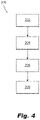
Fig. 4 is schematic box diagram of a method. - Reference will now be made to the drawings wherein like reference numerals identify similar structural features or aspects of the subject disclosure. For purposes of explanation and illustration, and not limitation, a partial view of an embodiment of a system in accordance with the disclosure is shown in
Fig. 1 and is designated generally byreference character 100. Other embodiments of systems in accordance with the disclosure, or aspects thereof, are provided inFigs. 2-4 , as will be described. The systems and methods described herein can be used to sanitize gasper knobs. - An air
gasper knob system 100 for an overhead Passenger Service Unit (PSU) 10 can include at least oneannular gasper knob 102 of a UV transparent material, theknob 102 having a firstannular end face 104 and a secondannular end face 106. Theannular gasper knob 102 can define anair passage 108, and can extend about theair passage 106, for example from the firstannular end face 104 to the secondannular end face 106. - The
system 100 can also include aUV illuminator 110 mounted to thegasper knob 102. For example, theUV illuminator 110 can include a light emitting diode (LED) configured to emitUV illumination 112 through the UV transparent material, or can include a strip of LEDs. TheUV illuminator 110 can be oriented to sanitize exterior surfaces of thegasper knob 102. For example, theUV illuminator 110 can be embedded (e.g. via additive manufacturing) in thegasper knob 102 and if the UV illuminator is a strip of LEDS, the strip can be annular and embedded in thegasper knob 102 proximate to the firstannular end face 104 of thegasper knob 102. In this configuration, the strip of LEDs can be embedded in the gasper knob so that the LEDs are oriented to illuminate toward the secondannular end face 106 of thegasper knob 102. Typically when sanitizing surfaces with UV illumination, surfaces of small components, such asgasper knobs 102, might escape the UV rays line of sight and might not get effectively sanitized if UV illumination is applied to the cabin indiscriminately. By embedding the UV illuminator directly in thegasper knob 102, such as described herein, effective sanitization of thegasper knob 102 can be achieved. - The
system 100 can also include avalve assembly 114 configured to open and close a flow of air by turning (e.g. twisting) the gasper knob about an axis of rotation R. The firstannular end face 104 can be at aninlet end 116 of thegasper knob 102 mounted to thevalve assembly 114, and the secondannular end face 106 can be at anoutlet end 118 of thegasper knob 102, extending away from thevalve assembly 114. In embodiments, thevalve assembly 114 can include acentral cone 120 configured to engage and disengage arim 122 in thevalve assembly 114. For example, the air flow through thegasper knob 102 can be controlled by turning thegasper knob 102, where in the open position, air from a pressurizedair source 124 can be fluid communication with thevalve assembly 114, and in the closed position, airflow from the pressurizedsource 124 can be restricted. - The
system 100 can further include, for example in thePSU 10, at least one reading light 126 and/or at least one flightattendant call button 128 mounted in aPSU panel 130 with thevalve assembly 114. The reading light(s) 126 and call button(s) 128 can be electrically connected to a source ofelectrical power 132, and the UV illuminator(s) 110 can be electrically connected to the same source ofelectrical power 132. If thesystem 100 includes a plurality ofgasper knobs 102, eachknob 102 can include itsown UV illuminator 110, and eachUV illuminator 110 can also be electrically connected to the source ofelectrical power 132. - A
method 200 of sanitizing an air gasper knob (e.g. knob 102) in aPSU 10 can include, atbox 202, illuminating agasper knob 102 in anoverhead PSU 110 using UV illumination (e.g. using illuminator 110) to destroy infectious agents (e.g. bacteria and/or viruses) on surfaces of thegasper knob 102. Illuminating 202 the gasper knob can include illuminating all exposed surfaces of thegasper knob 102, for example all surfaces in which a passenger seated below thePSU 10 may interact with during the flight. This can be accomplished using embedded illuminators that transmit illumination through the gasper knob itself. During flight, a passenger typically adjusts the air flow rate through the gasper knob by adjusting it manually, as described above. Micro-organisms and other infectious agents present on the hands of a passenger may then transfer from the hand of the passenger to the external surface of the gasper knob and then to the air outlet. This can provide a pathway for microorganisms to spread inside the cabin through air coming from the gasper outlet, in addition to a passenger in the next flight coming into contact with any microorganisms left behind. - The
method 200 can include powering theilluminator 110 with a supply of electrical power within thePSU 10, for example using source ofelectrical power 132, as shown atbox 204. Atbox 206, themethod 200 can also include illuminating theUV illuminator 110 after passengers have disembarked the aircraft cabin. Atbox 208, themethod 200 can further include deactivating theilluminator 110 prior to passengers boarding the aircraft cabin, for example so passengers are not exposed to UV radiation from theUV illuminator 110. The UV illuminators 110 can be connected so that they can be activated and deactivated by a non-passenger user (e.g. flight staff) using a single switch. - These and other features of the systems and methods of the subject disclosure will become more readily apparent to those skilled in the art from the following detailed description taken in conjunction with the drawings. The methods and systems of the present disclosure, as described above and shown in the drawings, provide for more efficient and effective sanitization of small aircraft components, such as gasper knobs and other equipment within a passenger service unit. While the apparatus and methods of the subject disclosure have been shown and described, those skilled in the art will readily appreciate that changes and/or modifications may be made thereto without departing from the scope of the invention as defined by the claims.
Claims (15)
- An air gasper knob system for an overhead Passenger Service Unit, PSU, the system comprising:an annular gasper knob (102) of a UV transparent material, wherein the annular gasper knob defines an air passage (108) therethrough, and where the annular gasper knob extends about the air passage from a first annular end face (104) to a second annular end face (106); anda UV illuminator (110) mounted to the gasper knob, oriented to transmit UV illumination through the UV transparent material to sanitize exterior surfaces of the gasper knob.
- The system as recited in claim 1, wherein the UV illuminator is embedded in the gasper knob.
- The system as recited in claim 1 or 2, wherein the UV illuminator includes a light emitting diode, LED, configured to emit UV illumination.
- The system as recited in any preceding claim, wherein the UV illuminator includes a strip of LEDs configured to emit UV illumination.
- The system as recited in claim 4, wherein the strip of LEDs is annular and is embedded in the gasper knob proximate to the first annular end face of the gasper knob.
- The system as recited in claim 5, wherein the strip of LEDs is embedded in the gasper knob with the LEDs oriented to illuminate toward the second annular end face of the gasper knob.
- The system as recited in claim 6, further comprising a valve assembly (114) configured to open and close a flow of air by turning the gasper knob about an axis of rotation, wherein the first annular end face of the gasper knob is at an inlet end (116) of the gasper knob mounted to the valve assembly, and wherein the second annular end face of the gasper knob is at an outlet end of the gasper knob extending away from the nozzle assembly.
- The system as recited in claim 7, wherein the valve assembly includes a central cone (120) configured to engage and disengage a rim (122) in the valve assembly by turning of the gasper knob to control air flow through the gasper knob from a pressurized air source in fluid communication with the valve assembly.
- The system as recited in claim 8, further comprising at least one reading light (126) and/or at least one flight attendant call button (128) mounted in a PSU panel (130) with the valve assembly, wherein the at least one reading light and/or at least one flight attendant call button are electrically connected to a source of electrical power, and wherein the LEDs are electrically connected to the source of electrical power.
- The system as recited in claim 9, wherein the gasper knob is one of a plurality of gasper knobs each having a respective illuminator electrically connected to the source of electrical power.
- A method of sanitizing an air gasper knob, the method comprising:
illuminating a gasper knob (102) in an overhead PSU (10) using UV illumination to destroy infectious agents on surfaces of the gasper knob. - The method as recited in claim 11, wherein illuminating includes illuminating all exposed surfaces of the gasper knob.
- The method as recited in claim 12, wherein illuminating includes using a UV illuminator (110) embedded in the gasper knob, further comprising powering the illuminator with a supply of electrical power within the PSU.
- The method as recited in claim 13, further comprising illuminating the UV illuminator after passengers have disembarked the aircraft cabin.
- The method as recited in claim 14, further comprising deactivating the illuminator prior to passengers boarding the aircraft cabin.
Applications Claiming Priority (1)
| Application Number | Priority Date | Filing Date | Title |
|---|---|---|---|
| IN202141004518 | 2021-02-02 |
Publications (2)
| Publication Number | Publication Date |
|---|---|
| EP4036012A1 true EP4036012A1 (en) | 2022-08-03 |
| EP4036012B1 EP4036012B1 (en) | 2025-08-27 |
Family
ID=80225459
Family Applications (1)
| Application Number | Title | Priority Date | Filing Date |
|---|---|---|---|
| EP22154820.9A Active EP4036012B1 (en) | 2021-02-02 | 2022-02-02 | Gasper knob sanitization |
Country Status (2)
| Country | Link |
|---|---|
| US (2) | US12178927B2 (en) |
| EP (1) | EP4036012B1 (en) |
Families Citing this family (2)
| Publication number | Priority date | Publication date | Assignee | Title |
|---|---|---|---|---|
| CN115554433B (en) * | 2022-10-09 | 2023-11-17 | 中国商用飞机有限责任公司 | Cabin disinfection system, cabin disinfection method and vehicle |
| USD1051013S1 (en) * | 2023-01-24 | 2024-11-12 | Textron Innovations, Inc. | Cabin ceiling |
Citations (4)
| Publication number | Priority date | Publication date | Assignee | Title |
|---|---|---|---|---|
| US20150090839A1 (en) * | 2013-09-30 | 2015-04-02 | Peco Manufacturing Co., Inc. | Passenger Service Unit and Related Systems |
| WO2017204774A1 (en) * | 2016-05-23 | 2017-11-30 | GM Global Technology Operations LLC | Germicidal uv-c treatments |
| CN209143418U (en) * | 2018-09-27 | 2019-07-23 | 苏州新里程电控系统有限公司 | A kind of elevator ultrathin type outgoing call hall buttons |
| WO2020146138A1 (en) * | 2019-01-07 | 2020-07-16 | Uv Partners, Inc. | Transportation disinfection |
Family Cites Families (5)
| Publication number | Priority date | Publication date | Assignee | Title |
|---|---|---|---|---|
| US6787782B1 (en) | 2003-04-23 | 2004-09-07 | B/E Aerospace, Inc. | Ultraviolet-light vehicle air cleaning system |
| JP2011143994A (en) | 2010-01-13 | 2011-07-28 | Toshiba Elevator Co Ltd | Elevator operation button device |
| KR20160015082A (en) | 2014-07-30 | 2016-02-12 | 서울바이오시스 주식회사 | Button device having sterilizing function |
| US20180361002A1 (en) | 2017-06-14 | 2018-12-20 | Ashlea Mastrocola | Sanitizing Assembly |
| DE102020104797A1 (en) * | 2020-02-24 | 2021-08-26 | Airbus Operations Gmbh | Passenger service unit with textile cover, passenger seating area and vehicle with passenger service unit |
-
2022
- 2022-02-01 US US17/590,730 patent/US12178927B2/en active Active
- 2022-02-02 EP EP22154820.9A patent/EP4036012B1/en active Active
-
2024
- 2024-11-27 US US18/962,553 patent/US20250090702A1/en active Pending
Patent Citations (4)
| Publication number | Priority date | Publication date | Assignee | Title |
|---|---|---|---|---|
| US20150090839A1 (en) * | 2013-09-30 | 2015-04-02 | Peco Manufacturing Co., Inc. | Passenger Service Unit and Related Systems |
| WO2017204774A1 (en) * | 2016-05-23 | 2017-11-30 | GM Global Technology Operations LLC | Germicidal uv-c treatments |
| CN209143418U (en) * | 2018-09-27 | 2019-07-23 | 苏州新里程电控系统有限公司 | A kind of elevator ultrathin type outgoing call hall buttons |
| WO2020146138A1 (en) * | 2019-01-07 | 2020-07-16 | Uv Partners, Inc. | Transportation disinfection |
Also Published As
| Publication number | Publication date |
|---|---|
| EP4036012B1 (en) | 2025-08-27 |
| US12178927B2 (en) | 2024-12-31 |
| US20250090702A1 (en) | 2025-03-20 |
| US20220241442A1 (en) | 2022-08-04 |
Similar Documents
| Publication | Publication Date | Title |
|---|---|---|
| US20250090702A1 (en) | Gasper knob sanitization | |
| US11273228B2 (en) | Cleaning and disinfecting cradle for items intended to be worn multiple times | |
| EP3691972B1 (en) | Method for disinfecting an aircraft cabin using a lighting assembly and a lighting assembly therefor | |
| US6787782B1 (en) | Ultraviolet-light vehicle air cleaning system | |
| KR101655187B1 (en) | UV disinfection device for detachable lift | |
| CA2973847C (en) | Ultraviolet light treating water dispensation systems and methods | |
| US20200217102A1 (en) | Antibacterial door knob | |
| EP3925630A1 (en) | Portable sanitizing systems and methods with range guidance | |
| EP3913169A1 (en) | Germicidal handles | |
| EP3970790B1 (en) | Lighting units producing visible light with blended disinfecting electromagnetic radiation | |
| EP4019052A1 (en) | Disinfection devices, systems, and materials | |
| EP3939619A1 (en) | Disinfection assembly | |
| US11969514B2 (en) | Sanitization systems and methods with FAR-UVC | |
| EP3960625B1 (en) | Reactive oxygen species (ros) enhanced antibacterial light system | |
| US12201737B2 (en) | Sanitization systems and methods with UVC lighting | |
| US20220234742A1 (en) | Aircraft Sanitizer | |
| CN113623809A (en) | Marine air conditioning system with composite disinfection structure and disinfection method | |
| EP4095047A1 (en) | Sanitization systems and methods with uvc lighting | |
| EP4124350B1 (en) | System and method for providing and monitoring uv illumination in an interior of an aircraft | |
| CN115554433B (en) | Cabin disinfection system, cabin disinfection method and vehicle | |
| US12629435B2 (en) | Sanitizing system | |
| KR20210145016A (en) | Terminal sterilization device |
Legal Events
| Date | Code | Title | Description |
|---|---|---|---|
| PUAI | Public reference made under article 153(3) epc to a published international application that has entered the european phase |
Free format text: ORIGINAL CODE: 0009012 |
|
| STAA | Information on the status of an ep patent application or granted ep patent |
Free format text: STATUS: THE APPLICATION HAS BEEN PUBLISHED |
|
| AK | Designated contracting states |
Kind code of ref document: A1 Designated state(s): AL AT BE BG CH CY CZ DE DK EE ES FI FR GB GR HR HU IE IS IT LI LT LU LV MC MK MT NL NO PL PT RO RS SE SI SK SM TR |
|
| STAA | Information on the status of an ep patent application or granted ep patent |
Free format text: STATUS: REQUEST FOR EXAMINATION WAS MADE |
|
| 17P | Request for examination filed |
Effective date: 20230203 |
|
| RBV | Designated contracting states (corrected) |
Designated state(s): AL AT BE BG CH CY CZ DE DK EE ES FI FR GB GR HR HU IE IS IT LI LT LU LV MC MK MT NL NO PL PT RO RS SE SI SK SM TR |
|
| STAA | Information on the status of an ep patent application or granted ep patent |
Free format text: STATUS: EXAMINATION IS IN PROGRESS |
|
| 17Q | First examination report despatched |
Effective date: 20240118 |
|
| GRAP | Despatch of communication of intention to grant a patent |
Free format text: ORIGINAL CODE: EPIDOSNIGR1 |
|
| RIC1 | Information provided on ipc code assigned before grant |
Ipc: A61L 2/10 20060101ALN20250217BHEP Ipc: B64D 11/00 20060101ALI20250217BHEP Ipc: B64D 13/00 20060101AFI20250217BHEP |
|
| STAA | Information on the status of an ep patent application or granted ep patent |
Free format text: STATUS: GRANT OF PATENT IS INTENDED |
|
| RIC1 | Information provided on ipc code assigned before grant |
Ipc: A61L 2/10 20060101ALN20250310BHEP Ipc: B64D 11/00 20060101ALI20250310BHEP Ipc: B64D 13/00 20060101AFI20250310BHEP |
|
| RIC1 | Information provided on ipc code assigned before grant |
Ipc: A61L 2/10 20060101ALN20250317BHEP Ipc: B64D 11/00 20060101ALI20250317BHEP Ipc: B64D 13/00 20060101AFI20250317BHEP |
|
| INTG | Intention to grant announced |
Effective date: 20250327 |
|
| RAP3 | Party data changed (applicant data changed or rights of an application transferred) |
Owner name: GOODRICH AEROSPACE SERVICES PVT LTD |
|
| RAP1 | Party data changed (applicant data changed or rights of an application transferred) |
Owner name: B/E AEROSPACE INC. |
|
| GRAS | Grant fee paid |
Free format text: ORIGINAL CODE: EPIDOSNIGR3 |
|
| GRAA | (expected) grant |
Free format text: ORIGINAL CODE: 0009210 |
|
| STAA | Information on the status of an ep patent application or granted ep patent |
Free format text: STATUS: THE PATENT HAS BEEN GRANTED |
|
| AK | Designated contracting states |
Kind code of ref document: B1 Designated state(s): AL AT BE BG CH CY CZ DE DK EE ES FI FR GB GR HR HU IE IS IT LI LT LU LV MC MK MT NL NO PL PT RO RS SE SI SK SM TR |
|
| REG | Reference to a national code |
Ref country code: CH Ref legal event code: EP |
|
| REG | Reference to a national code |
Ref country code: DE Ref legal event code: R096 Ref document number: 602022020022 Country of ref document: DE |
|
| REG | Reference to a national code |
Ref country code: IE Ref legal event code: FG4D |
|
| REG | Reference to a national code |
Ref country code: NL Ref legal event code: MP Effective date: 20250827 |
|
| PG25 | Lapsed in a contracting state [announced via postgrant information from national office to epo] |
Ref country code: IS Free format text: LAPSE BECAUSE OF FAILURE TO SUBMIT A TRANSLATION OF THE DESCRIPTION OR TO PAY THE FEE WITHIN THE PRESCRIBED TIME-LIMIT Effective date: 20251227 |
|
| PG25 | Lapsed in a contracting state [announced via postgrant information from national office to epo] |
Ref country code: NO Free format text: LAPSE BECAUSE OF FAILURE TO SUBMIT A TRANSLATION OF THE DESCRIPTION OR TO PAY THE FEE WITHIN THE PRESCRIBED TIME-LIMIT Effective date: 20251127 |
|
| REG | Reference to a national code |
Ref country code: LT Ref legal event code: MG9D |
|
| PG25 | Lapsed in a contracting state [announced via postgrant information from national office to epo] |
Ref country code: PT Free format text: LAPSE BECAUSE OF FAILURE TO SUBMIT A TRANSLATION OF THE DESCRIPTION OR TO PAY THE FEE WITHIN THE PRESCRIBED TIME-LIMIT Effective date: 20251229 |
|
| PG25 | Lapsed in a contracting state [announced via postgrant information from national office to epo] |
Ref country code: FI Free format text: LAPSE BECAUSE OF FAILURE TO SUBMIT A TRANSLATION OF THE DESCRIPTION OR TO PAY THE FEE WITHIN THE PRESCRIBED TIME-LIMIT Effective date: 20250827 |
|
| PG25 | Lapsed in a contracting state [announced via postgrant information from national office to epo] |
Ref country code: HR Free format text: LAPSE BECAUSE OF FAILURE TO SUBMIT A TRANSLATION OF THE DESCRIPTION OR TO PAY THE FEE WITHIN THE PRESCRIBED TIME-LIMIT Effective date: 20250827 Ref country code: NL Free format text: LAPSE BECAUSE OF FAILURE TO SUBMIT A TRANSLATION OF THE DESCRIPTION OR TO PAY THE FEE WITHIN THE PRESCRIBED TIME-LIMIT Effective date: 20250827 |
|
| PG25 | Lapsed in a contracting state [announced via postgrant information from national office to epo] |
Ref country code: GR Free format text: LAPSE BECAUSE OF FAILURE TO SUBMIT A TRANSLATION OF THE DESCRIPTION OR TO PAY THE FEE WITHIN THE PRESCRIBED TIME-LIMIT Effective date: 20251128 |
|
| PG25 | Lapsed in a contracting state [announced via postgrant information from national office to epo] |
Ref country code: SE Free format text: LAPSE BECAUSE OF FAILURE TO SUBMIT A TRANSLATION OF THE DESCRIPTION OR TO PAY THE FEE WITHIN THE PRESCRIBED TIME-LIMIT Effective date: 20250827 |
|
| PG25 | Lapsed in a contracting state [announced via postgrant information from national office to epo] |
Ref country code: LV Free format text: LAPSE BECAUSE OF FAILURE TO SUBMIT A TRANSLATION OF THE DESCRIPTION OR TO PAY THE FEE WITHIN THE PRESCRIBED TIME-LIMIT Effective date: 20250827 |
|
| PG25 | Lapsed in a contracting state [announced via postgrant information from national office to epo] |
Ref country code: PL Free format text: LAPSE BECAUSE OF FAILURE TO SUBMIT A TRANSLATION OF THE DESCRIPTION OR TO PAY THE FEE WITHIN THE PRESCRIBED TIME-LIMIT Effective date: 20250827 Ref country code: BG Free format text: LAPSE BECAUSE OF FAILURE TO SUBMIT A TRANSLATION OF THE DESCRIPTION OR TO PAY THE FEE WITHIN THE PRESCRIBED TIME-LIMIT Effective date: 20250827 |
|
| PG25 | Lapsed in a contracting state [announced via postgrant information from national office to epo] |
Ref country code: RS Free format text: LAPSE BECAUSE OF FAILURE TO SUBMIT A TRANSLATION OF THE DESCRIPTION OR TO PAY THE FEE WITHIN THE PRESCRIBED TIME-LIMIT Effective date: 20251127 |
|
| PG25 | Lapsed in a contracting state [announced via postgrant information from national office to epo] |
Ref country code: ES Free format text: LAPSE BECAUSE OF FAILURE TO SUBMIT A TRANSLATION OF THE DESCRIPTION OR TO PAY THE FEE WITHIN THE PRESCRIBED TIME-LIMIT Effective date: 20250827 |
|
| REG | Reference to a national code |
Ref country code: AT Ref legal event code: MK05 Ref document number: 1829754 Country of ref document: AT Kind code of ref document: T Effective date: 20250827 |
|
| PG25 | Lapsed in a contracting state [announced via postgrant information from national office to epo] |
Ref country code: SM Free format text: LAPSE BECAUSE OF FAILURE TO SUBMIT A TRANSLATION OF THE DESCRIPTION OR TO PAY THE FEE WITHIN THE PRESCRIBED TIME-LIMIT Effective date: 20250827 |
|
| PG25 | Lapsed in a contracting state [announced via postgrant information from national office to epo] |
Ref country code: DK Free format text: LAPSE BECAUSE OF FAILURE TO SUBMIT A TRANSLATION OF THE DESCRIPTION OR TO PAY THE FEE WITHIN THE PRESCRIBED TIME-LIMIT Effective date: 20250827 |
|
| PGFP | Annual fee paid to national office [announced via postgrant information from national office to epo] |
Ref country code: DE Payment date: 20260121 Year of fee payment: 5 |
|
| PG25 | Lapsed in a contracting state [announced via postgrant information from national office to epo] |
Ref country code: AT Free format text: LAPSE BECAUSE OF FAILURE TO SUBMIT A TRANSLATION OF THE DESCRIPTION OR TO PAY THE FEE WITHIN THE PRESCRIBED TIME-LIMIT Effective date: 20250827 |
|
| PG25 | Lapsed in a contracting state [announced via postgrant information from national office to epo] |
Ref country code: IT Free format text: LAPSE BECAUSE OF FAILURE TO SUBMIT A TRANSLATION OF THE DESCRIPTION OR TO PAY THE FEE WITHIN THE PRESCRIBED TIME-LIMIT Effective date: 20250827 |
|
| PGFP | Annual fee paid to national office [announced via postgrant information from national office to epo] |
Ref country code: FR Payment date: 20260121 Year of fee payment: 5 |
|
| PG25 | Lapsed in a contracting state [announced via postgrant information from national office to epo] |
Ref country code: CZ Free format text: LAPSE BECAUSE OF FAILURE TO SUBMIT A TRANSLATION OF THE DESCRIPTION OR TO PAY THE FEE WITHIN THE PRESCRIBED TIME-LIMIT Effective date: 20250827 |
|
| PG25 | Lapsed in a contracting state [announced via postgrant information from national office to epo] |
Ref country code: EE Free format text: LAPSE BECAUSE OF FAILURE TO SUBMIT A TRANSLATION OF THE DESCRIPTION OR TO PAY THE FEE WITHIN THE PRESCRIBED TIME-LIMIT Effective date: 20250827 Ref country code: SK Free format text: LAPSE BECAUSE OF FAILURE TO SUBMIT A TRANSLATION OF THE DESCRIPTION OR TO PAY THE FEE WITHIN THE PRESCRIBED TIME-LIMIT Effective date: 20250827 |