EP4036006A1 - Ceiling mounted tray systems - Google Patents
Ceiling mounted tray systems Download PDFInfo
- Publication number
- EP4036006A1 EP4036006A1 EP22154505.6A EP22154505A EP4036006A1 EP 4036006 A1 EP4036006 A1 EP 4036006A1 EP 22154505 A EP22154505 A EP 22154505A EP 4036006 A1 EP4036006 A1 EP 4036006A1
- Authority
- EP
- European Patent Office
- Prior art keywords
- assembly
- pair
- control box
- recited
- housing
- Prior art date
- Legal status (The legal status is an assumption and is not a legal conclusion. Google has not performed a legal analysis and makes no representation as to the accuracy of the status listed.)
- Granted
Links
Images




Classifications
-
- B—PERFORMING OPERATIONS; TRANSPORTING
- B64—AIRCRAFT; AVIATION; COSMONAUTICS
- B64D—EQUIPMENT FOR FITTING IN OR TO AIRCRAFT; FLIGHT SUITS; PARACHUTES; ARRANGEMENT OR MOUNTING OF POWER PLANTS OR PROPULSION TRANSMISSIONS IN AIRCRAFT
- B64D11/00—Passenger or crew accommodation; Flight-deck installations not otherwise provided for
- B64D11/0007—Devices specially adapted for food or beverage distribution services
-
- B—PERFORMING OPERATIONS; TRANSPORTING
- B65—CONVEYING; PACKING; STORING; HANDLING THIN OR FILAMENTARY MATERIAL
- B65G—TRANSPORT OR STORAGE DEVICES, e.g. CONVEYORS FOR LOADING OR TIPPING, SHOP CONVEYOR SYSTEMS OR PNEUMATIC TUBE CONVEYORS
- B65G17/00—Conveyors having an endless traction element, e.g. a chain, transmitting movement to a continuous or substantially-continuous load-carrying surface or to a series of individual load-carriers; Endless-chain conveyors in which the chains form the load-carrying surface
- B65G17/20—Conveyors having an endless traction element, e.g. a chain, transmitting movement to a continuous or substantially-continuous load-carrying surface or to a series of individual load-carriers; Endless-chain conveyors in which the chains form the load-carrying surface comprising load-carriers suspended from overhead traction chains
-
- B—PERFORMING OPERATIONS; TRANSPORTING
- B65—CONVEYING; PACKING; STORING; HANDLING THIN OR FILAMENTARY MATERIAL
- B65G—TRANSPORT OR STORAGE DEVICES, e.g. CONVEYORS FOR LOADING OR TIPPING, SHOP CONVEYOR SYSTEMS OR PNEUMATIC TUBE CONVEYORS
- B65G17/00—Conveyors having an endless traction element, e.g. a chain, transmitting movement to a continuous or substantially-continuous load-carrying surface or to a series of individual load-carriers; Endless-chain conveyors in which the chains form the load-carrying surface
- B65G17/30—Details; Auxiliary devices
- B65G17/32—Individual load-carriers
- B65G17/34—Individual load-carriers having flat surfaces, e.g. platforms, grids, forks
-
- B—PERFORMING OPERATIONS; TRANSPORTING
- B65—CONVEYING; PACKING; STORING; HANDLING THIN OR FILAMENTARY MATERIAL
- B65G—TRANSPORT OR STORAGE DEVICES, e.g. CONVEYORS FOR LOADING OR TIPPING, SHOP CONVEYOR SYSTEMS OR PNEUMATIC TUBE CONVEYORS
- B65G17/00—Conveyors having an endless traction element, e.g. a chain, transmitting movement to a continuous or substantially-continuous load-carrying surface or to a series of individual load-carriers; Endless-chain conveyors in which the chains form the load-carrying surface
- B65G17/30—Details; Auxiliary devices
- B65G17/48—Controlling attitudes of load-carriers during movement
- B65G17/485—Controlling attitudes of load-carriers during movement the load carriers being suspended
-
- B—PERFORMING OPERATIONS; TRANSPORTING
- B65—CONVEYING; PACKING; STORING; HANDLING THIN OR FILAMENTARY MATERIAL
- B65G—TRANSPORT OR STORAGE DEVICES, e.g. CONVEYORS FOR LOADING OR TIPPING, SHOP CONVEYOR SYSTEMS OR PNEUMATIC TUBE CONVEYORS
- B65G2201/00—Indexing codes relating to handling devices, e.g. conveyors, characterised by the type of product or load being conveyed or handled
- B65G2201/02—Articles
- B65G2201/0235—Containers
- B65G2201/0258—Trays, totes or bins
Definitions
- the present disclosure relates to refreshment service on commercial aircraft carriers, and more particularly to refreshment tray, such as those found on commercial aircraft.
- a ceiling-mounted delivery assembly for a cabin of a vehicle includes a conveyance system that has a pair of guide rails, and a trolley operatively connected to the conveyance system for movement relative thereto.
- the trolley includes a control box having a pair of wheels. Each wheel is operatively connected to a respective one of the pair of guide rails.
- the control box includes a plurality of pulley drums extending from the control box.
- the trolley includes cable connection system having a plurality of cables. Each cable attached to a respective one of the pulley drums of the control box.
- the trolley includes a tray operatively connected to the cables of the cable connection system to be moved up and down relative to the control box.
- the conveyance system includes a housing bolted to and extending from a ceiling of a cabin wherein the guide rails are mounted to the housing.
- the control box can include a housing and a drive axle extending therethrough. Each wheel of the pair of wheels is attached to an opposite end of the drive axle.
- the control box can include a pair of pulley axles extending through the housing. Each pulley axle can include one of the plurality of pulley drums at opposing ends thereof.
- the control box can include a drive assembly operatively connected to at least one of the drive axle or the pair of pulley axles.
- the drive assembly can be configured and adapted to rotate at least one of the drive axle or the pair of pulley axles.
- Each guide rail can have at least one of an I-shape, an L-shape or a C-shape.
- the drive assembly includes an electric motor and a pair of belt drives, wherein the pair of belt drives are operatively connected to the pair of pulley axles for providing rotation thereto.
- the drive assembly can include an electric motor and a wheel belt drive.
- the wheel belt drive is operatively connected to the drive axle for providing rotation thereto.
- the drive assembly can include a motor controller and an electric motor.
- the motor controller is configured and adapted to control operation of the electric motor.
- the drive assembly can include a force sensor system configured and adapted to detect abnormal G-forces.
- the force sensor system can be in electrical communication with the motor controller. When G-forces reach a given threshold, the tray can be retracted upwards by winding up one or more cables to preserve safety for passengers and crew and reduce likelihood of injury or damage during high-turbulence situations.
- the pair of wheels of the trolley are tapered from small to large in an outward direction relative to the housing.
- the pair of guide rails can include at least one arcuate portion.
- the control box can include a housing and ultra-violet (UV) lights.
- UV lights can be mounted between the housing and the tray to provide sanitization or decontamination to the tray.
- Each of the cables includes a hook. Each hook is configured and adapted to removably connect to a respective portion of the tray.
- a vehicle cabin includes a cabin ceiling, a ceiling-mounted delivery assembly.
- the ceiling-mounted delivery assembly includes a conveyance system mounted to the cabin ceiling.
- the conveyance system including a pair of guide rails.
- the ceiling-mounted delivery assembly includes a trolley operatively connected to the conveyance system for movement relative thereto.
- the trolley includes a control box having a pair of wheels, each wheel operatively connected to a respective guide rail of the pair of guide rails, and a plurality of pulley drums extending from the control box.
- the trolley includes a cable connection system including a plurality of cables, each cable attached to a respective one of the pulley drums of the control box.
- the trolley includes a tray operatively connected to the cables of the cable connection system to be moved up and down relative to the control box.
- the conveyance system including a housing that forms a track in the cabin interior.
- the track can have at least one arcuate portion.
- a partial view of an embodiment of a ceiling-mounted delivery assembly in accordance with the disclosure is shown in Fig. 1 and is designated generally by reference character 100.
- Other embodiments of systems in accordance with the disclosure, or aspects thereof, are provided in Figs. 2-7 as will be described.
- the systems and methods described herein can provide a delivery assembly, e.g. a delivery assembly for meals, newspapers, souvenirs food and the like, that is less intrusive on aisle space and lighter than traditional trolleys.
- Assembly 100 described below, is easier to operate/move along the aisle as it is supported by two set of rollers on the ceiling. In case of passenger movement, the tray system can be raised-up/retracted by cables to allow movement.
- a vehicle cabin 10 e.g. an aircraft cabin, includes a cabin ceiling 12 and a ceiling-mounted delivery assembly 100.
- the ceiling-mounted delivery assembly 100 includes a conveyance system 102 bolted to a ceiling 12 of the cabin 10.
- the conveyance system 102 includes a housing 118 bolted to and extending from a ceiling of cabin 10.
- the conveyance system 102 includes a pair of guide rails 108 mounted to the housing 118 to provide the path for movement of a trolley, described below.
- Guide rails 108 can have a cross-section with an I-shape, a C-shape, and/or an L-shape.
- the twin guide rail 108 arrangement provides stability and avoids swaying effects.
- the assembly 100 includes the trolley 104 operatively connected to the conveyance system 102 for movement relative thereto.
- the trolley 104 includes a control box 106 having a pair of wheels 110.
- Each wheel 110 is operatively connected to a respective one of the pair of guide rails 108 to translate along the guide rails 108.
- the wheels 110 roll on the rails 108 and aid in forward to aft movement along an axis A, along an aisle of an aircraft, for example.
- the two wheel design provides lateral stability and avoids swaying because of nonuniform weight on the tray.
- the two wheel design is also more stable as compared to a single wheel design.
- the control box 106 includes a housing 120.
- the diameter of each wheel 110 of the trolley 104 is tapered from a small diameter D 1 to larger diameter D 2 in an outward direction relative to the housing 120. This tapering helps to assist with turning when a track 101 (shown in Fig. 7 ) formed by conveyance system 102 is curved.
- the advantage of having these tapered wheels is to eliminate the need of a differential gear while turning.
- the track 101 can be curved and connect the galley area 14 with the aisle area 8.
- the conveyance system 102 can form a track 101 with two linear segments 101b joined by an arcuate portion 101a.
- the pair of guide rails 108 includes arcuate portion 108a.
- the tapered wheel design helps the tray system to effectively turn on the curved rails 108 thereby making it suitable for routings to the galley and/or for use on multi-isle aircrafts.
- the control box 106 includes a plurality of pulley drums 112 extending therefrom.
- the trolley 104 includes cable connection system 114 having a plurality of cables 116.
- cables 116 include a hook 140.
- the trolley 104 includes a tray 107 operatively connected to the cables 116 of the cable connection system 114 via the hooks 140 to be moved up and down relative to the control box 106.
- Each hook 140 is configured and adapted to removably connect to a respective portion of the tray 107.
- Each cable 116 is attached to a respective one of the pulley drums 112 of the control box 106 at one end and removably connected to the tray 107 at the other.
- Each cable 116 is configured and adapted to coil about its respective pulley drum 112 as the pulley drums 112 are rotated to retract the tray 107 upwards.
- the drums can rotate in both directions to control the up-down motion of the tray.
- the control box 106 includes a drive axle 122 extending therethrough. Each wheel of the pair of wheels 110 is attached to an opposite end of the drive axle 122.
- the control box 106 includes a pair of pulley axles 124 extending through the housing 120. Each pulley axle 124 includes one of the pulley drums 112 at each end thereof.
- the control box 106 includes a drive assembly 126 operatively connected to at least one of the drive axle 122 or the pair of pulley axles 124.
- the drive assembly 126 is configured and adapted to drive the rotation of the drive axle 122 and/or the pair of pulley axles 124.
- the assembly 100 can be motorized to carry orders to the passenger autonomously.
- the tray can be configured as per the requirements (passenger order) in the galley and then sent along the conveyance system 102.
- the drive assembly 126 includes an electric motor 128 and a transmission, such as belt drives 130, that engage with respective gears 135 on the pulley axels 124 for providing rotation thereto.
- Other transmission devices, such as gear drives, can also be used as transmission devices, depending on size requirements.
- the drive assembly 126 includes a wheel belt drive 132, which can also be another type of transmission device, such as gear drives.
- the wheel belt drive 132 is operatively connected to a gear 137 of the drive axle 122 for providing rotation thereto.
- the drive assembly 126 includes a motor controller 134 configured and adapted to control operation of the electric motor 128.
- the electric motor 128 is configured and adapted to drive the pulley axles 124 and the drive axle 122 at the same time, or the pulley axles and the drive axle 122 separately.
- electric motor can include a multi-axel drive for driving the forward-aft movement of the control box 106 and up-down movement of the cables.
- the electric motor 128 is also configured and adapted to drive rotation in box directions.
- the drive assembly 126 can include a second electric motor 128, such that one electric motor drives the drive axle 122 and the other drives the pulley axles 124.
- the drive assembly 126 includes a force sensor system 136 configured and adapted to detect abnormal G-forces.
- the force sensor system 136 is in electrical communication with the motor controller 134 such that when G-forces reach a given threshold, the tray 107 can be retracted upwards by winding up one or more cables 116 to preserve safety for passengers and crew and reduce likelihood of injury or damage during high-turbulence situations.
- the control box 106 includes ultra-violet (UV) lights 138.
- the UV lights 138 are mounted between the housing 120 and the tray 107.
- UV lights 138 may be commanded on after each time the tray 107 is retracted upwards to kill various viruses and bacteria on tray 107 in between uses.
- the UV lights can be customized to disinfect at the beginning or end of the flight or at the beginning or end of a food service, e.g., at beginning or end of serving a dinner meal, instead of after each tray retraction.
- the tray 107 can also be slotted to hold different food items securely, e.g., may include a cup holder, bowl holder, etc.
Landscapes
- Engineering & Computer Science (AREA)
- Mechanical Engineering (AREA)
- Aviation & Aerospace Engineering (AREA)
- Handcart (AREA)
Abstract
Description
- The present disclosure relates to refreshment service on commercial aircraft carriers, and more particularly to refreshment tray, such as those found on commercial aircraft.
- Many commercial aircraft include a trolley used by the flight attendants to serve food and beverages for the passengers. The traditional trolleys used in aircrafts to serve refreshments have limitations with mobility, as it is heavier to push around and blocks the aisle way. During turbulence, there is a risk of traditional trolleys hurting the passengers leading to accidents, posing question on safety. Additionally, serving refreshments to passenger poses a logistical challenge, as large trolley has to be used even for isolated/one-off serving request.
- The conventional techniques have been considered satisfactory for their intended purpose. However, there is an ever present need for improved systems and methods for more direct and safer refreshment service. This disclosure provides a solution for this need.
- A ceiling-mounted delivery assembly for a cabin of a vehicle includes a conveyance system that has a pair of guide rails, and a trolley operatively connected to the conveyance system for movement relative thereto. The trolley includes a control box having a pair of wheels. Each wheel is operatively connected to a respective one of the pair of guide rails. The control box includes a plurality of pulley drums extending from the control box. The trolley includes cable connection system having a plurality of cables. Each cable attached to a respective one of the pulley drums of the control box. The trolley includes a tray operatively connected to the cables of the cable connection system to be moved up and down relative to the control box.
- In some embodiments, the conveyance system includes a housing bolted to and extending from a ceiling of a cabin wherein the guide rails are mounted to the housing. The control box can include a housing and a drive axle extending therethrough. Each wheel of the pair of wheels is attached to an opposite end of the drive axle. The control box can include a pair of pulley axles extending through the housing. Each pulley axle can include one of the plurality of pulley drums at opposing ends thereof. The control box can include a drive assembly operatively connected to at least one of the drive axle or the pair of pulley axles. The drive assembly can be configured and adapted to rotate at least one of the drive axle or the pair of pulley axles. Each guide rail can have at least one of an I-shape, an L-shape or a C-shape.
- In some embodiments, the drive assembly includes an electric motor and a pair of belt drives, wherein the pair of belt drives are operatively connected to the pair of pulley axles for providing rotation thereto. The drive assembly can include an electric motor and a wheel belt drive. The wheel belt drive is operatively connected to the drive axle for providing rotation thereto. The drive assembly can include a motor controller and an electric motor. The motor controller is configured and adapted to control operation of the electric motor. The drive assembly can include a force sensor system configured and adapted to detect abnormal G-forces. The force sensor system can be in electrical communication with the motor controller. When G-forces reach a given threshold, the tray can be retracted upwards by winding up one or more cables to preserve safety for passengers and crew and reduce likelihood of injury or damage during high-turbulence situations.
- In some embodiments, the pair of wheels of the trolley are tapered from small to large in an outward direction relative to the housing. The pair of guide rails can include at least one arcuate portion. The control box can include a housing and ultra-violet (UV) lights. The UV lights can be mounted between the housing and the tray to provide sanitization or decontamination to the tray. Each of the cables includes a hook. Each hook is configured and adapted to removably connect to a respective portion of the tray.
- In accordance with another aspect, a vehicle cabin includes a cabin ceiling, a ceiling-mounted delivery assembly. The ceiling-mounted delivery assembly includes a conveyance system mounted to the cabin ceiling. The conveyance system including a pair of guide rails. The ceiling-mounted delivery assembly includes a trolley operatively connected to the conveyance system for movement relative thereto. The trolley includes a control box having a pair of wheels, each wheel operatively connected to a respective guide rail of the pair of guide rails, and a plurality of pulley drums extending from the control box. The trolley includes a cable connection system including a plurality of cables, each cable attached to a respective one of the pulley drums of the control box. The trolley includes a tray operatively connected to the cables of the cable connection system to be moved up and down relative to the control box.
- In some embodiments, the conveyance system including a housing that forms a track in the cabin interior. The track can have at least one arcuate portion.
- These and other features of the systems and methods of the subject disclosure will become more readily apparent to those skilled in the art from the following detailed description of the preferred embodiments taken in conjunction with the drawings.
- So that those skilled in the art to which the subject disclosure appertains will readily understand how to make and use the devices and methods of the subject disclosure without undue experimentation, preferred embodiments thereof will be described in detail herein below, by way of example only and with reference to certain figures, wherein:
-
Fig. 1 is a schematic perspective view of partial view of an embodiment of a ceiling-mounted delivery assembly constructed in accordance with the present disclosure, showing the trolley with the tray in an extended position; -
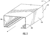
Fig. 2 is a schematic perspective view of the conveyance system of an embodiment of a ceiling-mounted delivery assembly constructed in accordance with the present disclosure, showing the guide rails; -
Fig. 3 is a schematic front plan view of a portion of the trolley ofFig. 1 and the conveyance system ofFig. 2 , showing the wheels of the trolley on the guide rails; -
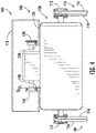
Fig. 4 is an enlarged schematic front plan view a portion of the trolley ofFig. 1 and the conveyance system ofFig. 2 , showing the pulley drums; -
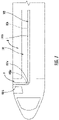
Fig. 5 is a schematic side plan view of a portion of the ceiling-mounted delivery assembly ofFig. 1 , showing the pulley drums each having a cable in an extended position; -
Fig. 6 is a schematic cross-sectional side plan view of the ceiling-mounted delivery assembly ofFig. 1 , showing a portion of the drive assembly; and -
Fig. 7 is a schematic top plan view of a portion of the ceiling-mounted delivery assembly ofFig. 1 , showing the track of the conveyance system on a single-aisle aircraft. - Reference will now be made to the drawings wherein like reference numerals identify similar structural features or aspects of the subject disclosure. For purposes of explanation and illustration, and not limitation, a partial view of an embodiment of a ceiling-mounted delivery assembly in accordance with the disclosure is shown in
Fig. 1 and is designated generally byreference character 100. Other embodiments of systems in accordance with the disclosure, or aspects thereof, are provided inFigs. 2-7 as will be described. The systems and methods described herein can provide a delivery assembly, e.g. a delivery assembly for meals, newspapers, souvenirs food and the like, that is less intrusive on aisle space and lighter than traditional trolleys.Assembly 100, described below, is easier to operate/move along the aisle as it is supported by two set of rollers on the ceiling. In case of passenger movement, the tray system can be raised-up/retracted by cables to allow movement. - As shown in
Figs. 1-3 , avehicle cabin 10, e.g. an aircraft cabin, includes acabin ceiling 12 and a ceiling-mounteddelivery assembly 100. The ceiling-mounteddelivery assembly 100 includes aconveyance system 102 bolted to aceiling 12 of thecabin 10. Theconveyance system 102 includes ahousing 118 bolted to and extending from a ceiling ofcabin 10. Theconveyance system 102 includes a pair ofguide rails 108 mounted to thehousing 118 to provide the path for movement of a trolley, described below.Guide rails 108 can have a cross-section with an I-shape, a C-shape, and/or an L-shape. Thetwin guide rail 108 arrangement provides stability and avoids swaying effects. Theassembly 100 includes thetrolley 104 operatively connected to theconveyance system 102 for movement relative thereto. Thetrolley 104 includes acontrol box 106 having a pair ofwheels 110. Eachwheel 110 is operatively connected to a respective one of the pair ofguide rails 108 to translate along the guide rails 108. Thewheels 110 roll on therails 108 and aid in forward to aft movement along an axis A, along an aisle of an aircraft, for example. The two wheel design provides lateral stability and avoids swaying because of nonuniform weight on the tray. The two wheel design is also more stable as compared to a single wheel design. - As shown in
Figs. 1 ,4 and7 , thecontrol box 106 includes ahousing 120. The diameter of eachwheel 110 of thetrolley 104 is tapered from a small diameter D1 to larger diameter D2 in an outward direction relative to thehousing 120. This tapering helps to assist with turning when a track 101 (shown inFig. 7 ) formed byconveyance system 102 is curved. The advantage of having these tapered wheels is to eliminate the need of a differential gear while turning. Hence, thetrack 101 can be curved and connect thegalley area 14 with the aisle area 8. In a single-aisle aircraft, theconveyance system 102 can form atrack 101 with twolinear segments 101b joined by anarcuate portion 101a. Accordingly, the pair ofguide rails 108 includesarcuate portion 108a. The tapered wheel design helps the tray system to effectively turn on thecurved rails 108 thereby making it suitable for routings to the galley and/or for use on multi-isle aircrafts. - As shown in
Fig. 1 , thecontrol box 106 includes a plurality ofpulley drums 112 extending therefrom. Thetrolley 104 includescable connection system 114 having a plurality ofcables 116. Those skilled in the art will also readily appreciate that ropes, re-tractable wires, or the like can all be used instead of cables. Each of thecables 116 includes ahook 140. Thetrolley 104 includes atray 107 operatively connected to thecables 116 of thecable connection system 114 via thehooks 140 to be moved up and down relative to thecontrol box 106. Eachhook 140 is configured and adapted to removably connect to a respective portion of thetray 107. Eachcable 116 is attached to a respective one of the pulley drums 112 of thecontrol box 106 at one end and removably connected to thetray 107 at the other. Eachcable 116 is configured and adapted to coil about itsrespective pulley drum 112 as the pulley drums 112 are rotated to retract thetray 107 upwards. The drums can rotate in both directions to control the up-down motion of the tray. - As shown in
Figs. 3 and6 , thecontrol box 106 includes adrive axle 122 extending therethrough. Each wheel of the pair ofwheels 110 is attached to an opposite end of thedrive axle 122. Thecontrol box 106 includes a pair ofpulley axles 124 extending through thehousing 120. Eachpulley axle 124 includes one of the pulley drums 112 at each end thereof. Thecontrol box 106 includes adrive assembly 126 operatively connected to at least one of thedrive axle 122 or the pair of pulley axles 124. Thedrive assembly 126 is configured and adapted to drive the rotation of thedrive axle 122 and/or the pair of pulley axles 124. - With reference now to
Fig. 6 , in some embodiments, theassembly 100 can be motorized to carry orders to the passenger autonomously. In such a scenario, the tray can be configured as per the requirements (passenger order) in the galley and then sent along theconveyance system 102. Thedrive assembly 126 includes anelectric motor 128 and a transmission, such as belt drives 130, that engage withrespective gears 135 on thepulley axels 124 for providing rotation thereto. Other transmission devices, such as gear drives, can also be used as transmission devices, depending on size requirements. Thedrive assembly 126 includes awheel belt drive 132, which can also be another type of transmission device, such as gear drives. Thewheel belt drive 132 is operatively connected to agear 137 of thedrive axle 122 for providing rotation thereto. Thedrive assembly 126 includes a motor controller 134 configured and adapted to control operation of theelectric motor 128. Theelectric motor 128 is configured and adapted to drive thepulley axles 124 and thedrive axle 122 at the same time, or the pulley axles and thedrive axle 122 separately. For example, electric motor can include a multi-axel drive for driving the forward-aft movement of thecontrol box 106 and up-down movement of the cables. Theelectric motor 128 is also configured and adapted to drive rotation in box directions. - Alternatively, the
drive assembly 126 can include a secondelectric motor 128, such that one electric motor drives thedrive axle 122 and the other drives the pulley axles 124. Thedrive assembly 126 includes aforce sensor system 136 configured and adapted to detect abnormal G-forces. Theforce sensor system 136 is in electrical communication with the motor controller 134 such that when G-forces reach a given threshold, thetray 107 can be retracted upwards by winding up one ormore cables 116 to preserve safety for passengers and crew and reduce likelihood of injury or damage during high-turbulence situations. Thecontrol box 106 includes ultra-violet (UV) lights 138. The UV lights 138 are mounted between thehousing 120 and thetray 107. UV lights 138 may be commanded on after each time thetray 107 is retracted upwards to kill various viruses and bacteria ontray 107 in between uses. Alternatively, the UV lights can be customized to disinfect at the beginning or end of the flight or at the beginning or end of a food service, e.g., at beginning or end of serving a dinner meal, instead of after each tray retraction. Those skilled in the art will readily appreciate that the timing of the sanitization with UV lights is customizable depending on the application. Thetray 107 can also be slotted to hold different food items securely, e.g., may include a cup holder, bowl holder, etc. - The methods and systems of the present disclosure, as described above and shown in the drawings, provide for ceiling-mounted delivery assemblies that are easier to operate/move along the aisle and is able to be raised-up/retracted by cables to allow passenger movement. While the apparatus and methods of the subject disclosure have been shown and described with reference to preferred embodiments, those skilled in the art will readily appreciate that changes and/or modifications may be made thereto without departing from the scope of the claims.
Claims (15)
- A ceiling-mounted delivery assembly (100) for a cabin (10) of a vehicle:a conveyance system (102) including a pair of guide rails (108);a trolley (104) operatively connected to the conveyance system for movement relative thereto, the trolley (104) including:a control box (106) having a pair of wheels (110), each wheel operatively connected to a respective one of the pair of guide rails (108), and a plurality of pulley drums (112) extending therefrom;a cable connection system (114) including a plurality of cables (116), each cable attached to a respective one of the pulley drums of the control box; anda tray (107) operatively connected to the cables of the cable connection system to be moved up and down relative to the control box.
- The assembly as recited in claim 1, wherein each guide rail (108) has at least one of an I-shape, an L-shape or a C-shape.
- The assembly as recited in claim 1 or 2, wherein the conveyance system includes a housing (120) bolted to and extending from a ceiling of a cabin (10) wherein the guide rails are mounted to the housing.
- The assembly as recited in claim 1 or 2, wherein the control box includes a housing (120) and a drive axle (122) extending therethrough, wherein each wheel of the pair of wheels is attached to an opposite end of the drive axle.
- The assembly as recited in claim 1 or 2, wherein the control box includes a housing (120) and a pair of pulley axles (124) extending therethrough, wherein each pulley axle includes one of the plurality of pulley drums (112) at opposing ends thereof.
- The assembly as recited in claim 1 or 2, wherein the control box includes a housing (120) and a drive axle (122) extending therethrough, wherein the control box includes a pair of pulley axles (124) extending through the housing, wherein the control box includes a drive assembly (126) operatively connected to at least one of the drive axle or the pair of pulley axles, wherein the drive assembly is configured and adapted to rotate at least one of the drive axle or the pair of pulley axles.
- The assembly as recited in claim 6, wherein the drive assembly includes an electric motor (128) and a pair of belt drives (130), wherein the pair of belt drives are operatively connected to the pair of pulley axles for providing rotation thereto.
- The assembly as recited in claim 6, wherein the drive assembly includes an electric motor (128) and a wheel belt drive (132), wherein the wheel belt drive is operatively connected to the drive axle for providing rotation thereto.
- The assembly as recited in claim 6, wherein the drive assembly includes a motor controller (134) and an electric motor (128), wherein the motor controller is configured and adapted to control operation of the electric motor; optionally wherein the drive assembly includes a force sensor system (136) configured and adapted to detect abnormal G-forces, wherein the force sensor system is in electrical communication with the motor controller.
- The assembly as recited in claim 1 or 2, wherein the control box includes a housing (120), wherein the pair of wheels of the trolley are tapered from small to large in an outward direction relative to the housing.
- The assembly as recited in any preceding claim, wherein the pair of guide rails include at least one arcuate portion.
- The assembly as recited in claim 1 or 2, wherein the control box includes a housing and ultra-violet, UV, lights, wherein the UV lights are mounted between the housing and the tray.
- The assembly as recited in claim 1, wherein the each of the cables includes a hook (140), wherein each hook (140) is configured and adapted to removably connect to a respective portion of the tray.
- A vehicle cabin comprising:a cabin ceiling (12); andthe ceiling-mounted delivery assembly (100) according to any preceding claim mounted to the cabin ceiling.
- The vehicle cabin as recited in claim 14, the conveyance system including a housing that forms a track in the cabin interior; optionally wherein the track has at least one arcuate portion.
Applications Claiming Priority (1)
| Application Number | Priority Date | Filing Date | Title |
|---|---|---|---|
| IN202141004340 | 2021-02-01 |
Publications (2)
| Publication Number | Publication Date |
|---|---|
| EP4036006A1 true EP4036006A1 (en) | 2022-08-03 |
| EP4036006B1 EP4036006B1 (en) | 2025-11-26 |
Family
ID=80118792
Family Applications (1)
| Application Number | Title | Priority Date | Filing Date |
|---|---|---|---|
| EP22154505.6A Active EP4036006B1 (en) | 2021-02-01 | 2022-02-01 | Ceiling mounted tray systems |
Country Status (2)
| Country | Link |
|---|---|
| US (1) | US11760487B2 (en) |
| EP (1) | EP4036006B1 (en) |
Citations (6)
| Publication number | Priority date | Publication date | Assignee | Title |
|---|---|---|---|---|
| US3102607A (en) * | 1960-12-19 | 1963-09-03 | Charles E Roberts | Carrier system for transport and delivery along a trackway |
| US5031861A (en) * | 1989-12-20 | 1991-07-16 | Wojdylo Henry K | System for serving and collecting items on board an aircraft |
| US20130199402A1 (en) * | 2010-04-19 | 2013-08-08 | P.A. Mohammed Ansar | Inflight catering apparatus |
| US20170101182A1 (en) * | 2015-10-13 | 2017-04-13 | International Business Machines Corporation | Overhead Delivery System for Transporting Products |
| US20180370634A1 (en) * | 2017-06-26 | 2018-12-27 | Marian Zdzislaw Augustyniak | Airliner overhead meals delivery |
| CN109552827A (en) * | 2018-10-11 | 2019-04-02 | 山东建筑大学 | A kind of hanger rail type movable power supply food delivery equipment |
Family Cites Families (9)
| Publication number | Priority date | Publication date | Assignee | Title |
|---|---|---|---|---|
| US1606627A (en) * | 1926-05-08 | 1926-11-09 | Gromer Wolfgang | Automatic self-serving buffet |
| US3558086A (en) | 1968-08-22 | 1971-01-26 | Stanley W Kraly | Food and beverage dispenser for passenger aircraft |
| US3999630A (en) | 1976-03-26 | 1976-12-28 | Mcphee Donald T | Transport and serving device |
| US6644441B1 (en) | 2001-03-23 | 2003-11-11 | Nercy B. Ebrahimi | Food storage and distribution system for airplanes |
| GB2388098B (en) | 2002-03-19 | 2006-02-01 | Vera Maud Benney | Air-bus catering trolley |
| US20080087767A1 (en) | 2006-10-17 | 2008-04-17 | Scott Frank M | Overhead food and beverage transport and serving device |
| DE102008026087B4 (en) | 2008-05-30 | 2010-11-11 | Airbus Deutschland Gmbh | Conveyor for a trolley in an aircraft cabin |
| FR2964085B1 (en) | 2010-08-24 | 2013-08-23 | Airbus Operations Sas | AUTOMATED FURNITURE STORAGE OF CARTS AND AIRCRAFT INCORPORATING SUCH A FURNITURE |
| US9706860B2 (en) * | 2013-12-13 | 2017-07-18 | Ping Li | Dish conveying device used in catering store |
-
2022
- 2022-02-01 US US17/589,987 patent/US11760487B2/en active Active
- 2022-02-01 EP EP22154505.6A patent/EP4036006B1/en active Active
Patent Citations (6)
| Publication number | Priority date | Publication date | Assignee | Title |
|---|---|---|---|---|
| US3102607A (en) * | 1960-12-19 | 1963-09-03 | Charles E Roberts | Carrier system for transport and delivery along a trackway |
| US5031861A (en) * | 1989-12-20 | 1991-07-16 | Wojdylo Henry K | System for serving and collecting items on board an aircraft |
| US20130199402A1 (en) * | 2010-04-19 | 2013-08-08 | P.A. Mohammed Ansar | Inflight catering apparatus |
| US20170101182A1 (en) * | 2015-10-13 | 2017-04-13 | International Business Machines Corporation | Overhead Delivery System for Transporting Products |
| US20180370634A1 (en) * | 2017-06-26 | 2018-12-27 | Marian Zdzislaw Augustyniak | Airliner overhead meals delivery |
| CN109552827A (en) * | 2018-10-11 | 2019-04-02 | 山东建筑大学 | A kind of hanger rail type movable power supply food delivery equipment |
Also Published As
| Publication number | Publication date |
|---|---|
| EP4036006B1 (en) | 2025-11-26 |
| US20220242567A1 (en) | 2022-08-04 |
| US11760487B2 (en) | 2023-09-19 |
Similar Documents
| Publication | Publication Date | Title |
|---|---|---|
| KR101848798B1 (en) | System for transporting people | |
| US11925716B2 (en) | Trolley with UV sanitation | |
| EP2991879B1 (en) | Transportation system and displacement device therefor | |
| CN101628624A (en) | Aircraft and method of retrieving a rescue cradle into the aircraft fuselage | |
| US11434007B2 (en) | Powered rail mounted cargo tug and cargo platform | |
| US11299291B2 (en) | System of driving channels for a carriage for transporting airplanes on an airport apron | |
| CN108137063B (en) | cable transport facility | |
| US9085367B2 (en) | Apparatus for moving an object on a rail | |
| US11760487B2 (en) | Ceiling mounted tray systems | |
| US10995808B1 (en) | Solenoid/magnetic hold brake with power off magnet hold function | |
| WO2007043463A1 (en) | Acceleration device | |
| DE102017201187B4 (en) | Service system for mass transit | |
| US20190151178A1 (en) | Patient ceiling-hoist carriage | |
| US20170101182A1 (en) | Overhead Delivery System for Transporting Products | |
| DE102018114292A1 (en) | Cart for moving on a surface and method for moving a cart on a surface | |
| US20170072969A1 (en) | Monorail system for movement of vehicles | |
| EP0069714A2 (en) | Bus for airport use | |
| US11685414B2 (en) | Device for transporting at least one passenger | |
| EP2261123A2 (en) | Mobilizing apparatus for airplanes | |
| EP3860735B1 (en) | Ride evacuation systems and methods | |
| EP3795442A1 (en) | Cabin for a transportation system, in particular for transporting passengers with skis or snowboards | |
| CN107444411B (en) | Cable Car Transmission Mechanism | |
| CN121038866A (en) | Guide rails, amusement rides with such guide rails, and methods for operating such amusement rides. | |
| GB2570896A (en) | Tram transportation system | |
| KR20160072935A (en) | railway vehicle for transferring bus |
Legal Events
| Date | Code | Title | Description |
|---|---|---|---|
| PUAI | Public reference made under article 153(3) epc to a published international application that has entered the european phase |
Free format text: ORIGINAL CODE: 0009012 |
|
| STAA | Information on the status of an ep patent application or granted ep patent |
Free format text: STATUS: THE APPLICATION HAS BEEN PUBLISHED |
|
| AK | Designated contracting states |
Kind code of ref document: A1 Designated state(s): AL AT BE BG CH CY CZ DE DK EE ES FI FR GB GR HR HU IE IS IT LI LT LU LV MC MK MT NL NO PL PT RO RS SE SI SK SM TR |
|
| STAA | Information on the status of an ep patent application or granted ep patent |
Free format text: STATUS: REQUEST FOR EXAMINATION WAS MADE |
|
| 17P | Request for examination filed |
Effective date: 20230203 |
|
| RBV | Designated contracting states (corrected) |
Designated state(s): AL AT BE BG CH CY CZ DE DK EE ES FI FR GB GR HR HU IE IS IT LI LT LU LV MC MK MT NL NO PL PT RO RS SE SI SK SM TR |
|
| STAA | Information on the status of an ep patent application or granted ep patent |
Free format text: STATUS: EXAMINATION IS IN PROGRESS |
|
| 17Q | First examination report despatched |
Effective date: 20230906 |
|
| P01 | Opt-out of the competence of the unified patent court (upc) registered |
Effective date: 20230922 |
|
| GRAP | Despatch of communication of intention to grant a patent |
Free format text: ORIGINAL CODE: EPIDOSNIGR1 |
|
| STAA | Information on the status of an ep patent application or granted ep patent |
Free format text: STATUS: GRANT OF PATENT IS INTENDED |
|
| INTG | Intention to grant announced |
Effective date: 20250623 |
|
| GRAS | Grant fee paid |
Free format text: ORIGINAL CODE: EPIDOSNIGR3 |
|
| GRAA | (expected) grant |
Free format text: ORIGINAL CODE: 0009210 |
|
| STAA | Information on the status of an ep patent application or granted ep patent |
Free format text: STATUS: THE PATENT HAS BEEN GRANTED |
|
| AK | Designated contracting states |
Kind code of ref document: B1 Designated state(s): AL AT BE BG CH CY CZ DE DK EE ES FI FR GB GR HR HU IE IS IT LI LT LU LV MC MK MT NL NO PL PT RO RS SE SI SK SM TR |
|
| REG | Reference to a national code |
Ref country code: CH Ref legal event code: F10 Free format text: ST27 STATUS EVENT CODE: U-0-0-F10-F00 (AS PROVIDED BY THE NATIONAL OFFICE) Effective date: 20251126 Ref country code: GB Ref legal event code: FG4D |
|
| REG | Reference to a national code |
Ref country code: DE Ref legal event code: R096 Ref document number: 602022025451 Country of ref document: DE |
|
| REG | Reference to a national code |
Ref country code: IE Ref legal event code: FG4D |
|
| REG | Reference to a national code |
Ref country code: NL Ref legal event code: MP Effective date: 20251126 |
|
| PG25 | Lapsed in a contracting state [announced via postgrant information from national office to epo] |
Ref country code: ES Free format text: LAPSE BECAUSE OF FAILURE TO SUBMIT A TRANSLATION OF THE DESCRIPTION OR TO PAY THE FEE WITHIN THE PRESCRIBED TIME-LIMIT Effective date: 20251126 |
|
| REG | Reference to a national code |
Ref country code: LT Ref legal event code: MG9D |
|
| PG25 | Lapsed in a contracting state [announced via postgrant information from national office to epo] |
Ref country code: NO Free format text: LAPSE BECAUSE OF FAILURE TO SUBMIT A TRANSLATION OF THE DESCRIPTION OR TO PAY THE FEE WITHIN THE PRESCRIBED TIME-LIMIT Effective date: 20260226 |
|
| PG25 | Lapsed in a contracting state [announced via postgrant information from national office to epo] |
Ref country code: AT Free format text: LAPSE BECAUSE OF FAILURE TO SUBMIT A TRANSLATION OF THE DESCRIPTION OR TO PAY THE FEE WITHIN THE PRESCRIBED TIME-LIMIT Effective date: 20251126 Ref country code: FI Free format text: LAPSE BECAUSE OF FAILURE TO SUBMIT A TRANSLATION OF THE DESCRIPTION OR TO PAY THE FEE WITHIN THE PRESCRIBED TIME-LIMIT Effective date: 20251126 Ref country code: HR Free format text: LAPSE BECAUSE OF FAILURE TO SUBMIT A TRANSLATION OF THE DESCRIPTION OR TO PAY THE FEE WITHIN THE PRESCRIBED TIME-LIMIT Effective date: 20251126 |
|
| PGFP | Annual fee paid to national office [announced via postgrant information from national office to epo] |
Ref country code: AT Payment date: 20260301 Year of fee payment: 5 |
|
| REG | Reference to a national code |
Ref country code: AT Ref legal event code: MK05 Ref document number: 1860858 Country of ref document: AT Kind code of ref document: T Effective date: 20251126 |
|
| PG25 | Lapsed in a contracting state [announced via postgrant information from national office to epo] |
Ref country code: NL Free format text: LAPSE BECAUSE OF FAILURE TO SUBMIT A TRANSLATION OF THE DESCRIPTION OR TO PAY THE FEE WITHIN THE PRESCRIBED TIME-LIMIT Effective date: 20251126 |
|
| PG25 | Lapsed in a contracting state [announced via postgrant information from national office to epo] |
Ref country code: RS Free format text: LAPSE BECAUSE OF FAILURE TO SUBMIT A TRANSLATION OF THE DESCRIPTION OR TO PAY THE FEE WITHIN THE PRESCRIBED TIME-LIMIT Effective date: 20260226 |
|
| PG25 | Lapsed in a contracting state [announced via postgrant information from national office to epo] |
Ref country code: IS Free format text: LAPSE BECAUSE OF FAILURE TO SUBMIT A TRANSLATION OF THE DESCRIPTION OR TO PAY THE FEE WITHIN THE PRESCRIBED TIME-LIMIT Effective date: 20260326 |
|
| PGFP | Annual fee paid to national office [announced via postgrant information from national office to epo] |
Ref country code: FR Payment date: 20260121 Year of fee payment: 5 |
|
| PG25 | Lapsed in a contracting state [announced via postgrant information from national office to epo] |
Ref country code: PT Free format text: LAPSE BECAUSE OF FAILURE TO SUBMIT A TRANSLATION OF THE DESCRIPTION OR TO PAY THE FEE WITHIN THE PRESCRIBED TIME-LIMIT Effective date: 20260326 |
|
| PG25 | Lapsed in a contracting state [announced via postgrant information from national office to epo] |
Ref country code: PL Free format text: LAPSE BECAUSE OF FAILURE TO SUBMIT A TRANSLATION OF THE DESCRIPTION OR TO PAY THE FEE WITHIN THE PRESCRIBED TIME-LIMIT Effective date: 20251126 |
|
| PG25 | Lapsed in a contracting state [announced via postgrant information from national office to epo] |
Ref country code: LV Free format text: LAPSE BECAUSE OF FAILURE TO SUBMIT A TRANSLATION OF THE DESCRIPTION OR TO PAY THE FEE WITHIN THE PRESCRIBED TIME-LIMIT Effective date: 20251126 |
|
| PG25 | Lapsed in a contracting state [announced via postgrant information from national office to epo] |
Ref country code: BG Free format text: LAPSE BECAUSE OF FAILURE TO SUBMIT A TRANSLATION OF THE DESCRIPTION OR TO PAY THE FEE WITHIN THE PRESCRIBED TIME-LIMIT Effective date: 20251126 |
|
| PG25 | Lapsed in a contracting state [announced via postgrant information from national office to epo] |
Ref country code: LT Free format text: LAPSE BECAUSE OF FAILURE TO SUBMIT A TRANSLATION OF THE DESCRIPTION OR TO PAY THE FEE WITHIN THE PRESCRIBED TIME-LIMIT Effective date: 20251126 |
|
| PG25 | Lapsed in a contracting state [announced via postgrant information from national office to epo] |
Ref country code: SM Free format text: LAPSE BECAUSE OF FAILURE TO SUBMIT A TRANSLATION OF THE DESCRIPTION OR TO PAY THE FEE WITHIN THE PRESCRIBED TIME-LIMIT Effective date: 20251126 |
|
| PG25 | Lapsed in a contracting state [announced via postgrant information from national office to epo] |
Ref country code: DK Free format text: LAPSE BECAUSE OF FAILURE TO SUBMIT A TRANSLATION OF THE DESCRIPTION OR TO PAY THE FEE WITHIN THE PRESCRIBED TIME-LIMIT Effective date: 20251126 |
|
| PG25 | Lapsed in a contracting state [announced via postgrant information from national office to epo] |
Ref country code: IT Free format text: LAPSE BECAUSE OF FAILURE TO SUBMIT A TRANSLATION OF THE DESCRIPTION OR TO PAY THE FEE WITHIN THE PRESCRIBED TIME-LIMIT Effective date: 20251126 |
|
| PG25 | Lapsed in a contracting state [announced via postgrant information from national office to epo] |
Ref country code: EE Free format text: LAPSE BECAUSE OF FAILURE TO SUBMIT A TRANSLATION OF THE DESCRIPTION OR TO PAY THE FEE WITHIN THE PRESCRIBED TIME-LIMIT Effective date: 20251126 |
|
| PG25 | Lapsed in a contracting state [announced via postgrant information from national office to epo] |
Ref country code: CZ Free format text: LAPSE BECAUSE OF FAILURE TO SUBMIT A TRANSLATION OF THE DESCRIPTION OR TO PAY THE FEE WITHIN THE PRESCRIBED TIME-LIMIT Effective date: 20251126 |
|
| PG25 | Lapsed in a contracting state [announced via postgrant information from national office to epo] |
Ref country code: SK Free format text: LAPSE BECAUSE OF FAILURE TO SUBMIT A TRANSLATION OF THE DESCRIPTION OR TO PAY THE FEE WITHIN THE PRESCRIBED TIME-LIMIT Effective date: 20251126 |
|
| PG25 | Lapsed in a contracting state [announced via postgrant information from national office to epo] |
Ref country code: SE Free format text: LAPSE BECAUSE OF FAILURE TO SUBMIT A TRANSLATION OF THE DESCRIPTION OR TO PAY THE FEE WITHIN THE PRESCRIBED TIME-LIMIT Effective date: 20251126 |