EP4035957B1 - Method of controlling a parking brake of a vehicle - Google Patents
Method of controlling a parking brake of a vehicle Download PDFInfo
- Publication number
- EP4035957B1 EP4035957B1 EP22152609.8A EP22152609A EP4035957B1 EP 4035957 B1 EP4035957 B1 EP 4035957B1 EP 22152609 A EP22152609 A EP 22152609A EP 4035957 B1 EP4035957 B1 EP 4035957B1
- Authority
- EP
- European Patent Office
- Prior art keywords
- vehicle
- parking brake
- hydraulic machine
- slope
- release
- Prior art date
- Legal status (The legal status is an assumption and is not a legal conclusion. Google has not performed a legal analysis and makes no representation as to the accuracy of the status listed.)
- Active
Links
Images

Classifications
-
- B—PERFORMING OPERATIONS; TRANSPORTING
- B60—VEHICLES IN GENERAL
- B60T—VEHICLE BRAKE CONTROL SYSTEMS OR PARTS THEREOF; BRAKE CONTROL SYSTEMS OR PARTS THEREOF, IN GENERAL; ARRANGEMENT OF BRAKING ELEMENTS ON VEHICLES IN GENERAL; PORTABLE DEVICES FOR PREVENTING UNWANTED MOVEMENT OF VEHICLES; VEHICLE MODIFICATIONS TO FACILITATE COOLING OF BRAKES
- B60T13/00—Transmitting braking action from initiating means to ultimate brake actuator with power assistance or drive; Brake systems incorporating such transmitting means, e.g. air-pressure brake systems
- B60T13/10—Transmitting braking action from initiating means to ultimate brake actuator with power assistance or drive; Brake systems incorporating such transmitting means, e.g. air-pressure brake systems with fluid assistance, drive, or release
- B60T13/66—Electrical control in fluid-pressure brake systems
- B60T13/68—Electrical control in fluid-pressure brake systems by electrically-controlled valves
- B60T13/686—Electrical control in fluid-pressure brake systems by electrically-controlled valves in hydraulic systems or parts thereof
-
- B—PERFORMING OPERATIONS; TRANSPORTING
- B60—VEHICLES IN GENERAL
- B60T—VEHICLE BRAKE CONTROL SYSTEMS OR PARTS THEREOF; BRAKE CONTROL SYSTEMS OR PARTS THEREOF, IN GENERAL; ARRANGEMENT OF BRAKING ELEMENTS ON VEHICLES IN GENERAL; PORTABLE DEVICES FOR PREVENTING UNWANTED MOVEMENT OF VEHICLES; VEHICLE MODIFICATIONS TO FACILITATE COOLING OF BRAKES
- B60T1/00—Arrangements of braking elements, i.e. of those parts where braking effect occurs specially for vehicles
- B60T1/02—Arrangements of braking elements, i.e. of those parts where braking effect occurs specially for vehicles acting by retarding wheels
- B60T1/08—Arrangements of braking elements, i.e. of those parts where braking effect occurs specially for vehicles acting by retarding wheels using fluid or powdered medium
- B60T1/093—Arrangements of braking elements, i.e. of those parts where braking effect occurs specially for vehicles acting by retarding wheels using fluid or powdered medium in hydrostatic, i.e. positive displacement, retarders
-
- B—PERFORMING OPERATIONS; TRANSPORTING
- B60—VEHICLES IN GENERAL
- B60T—VEHICLE BRAKE CONTROL SYSTEMS OR PARTS THEREOF; BRAKE CONTROL SYSTEMS OR PARTS THEREOF, IN GENERAL; ARRANGEMENT OF BRAKING ELEMENTS ON VEHICLES IN GENERAL; PORTABLE DEVICES FOR PREVENTING UNWANTED MOVEMENT OF VEHICLES; VEHICLE MODIFICATIONS TO FACILITATE COOLING OF BRAKES
- B60T10/00—Control or regulation for continuous braking making use of fluid or powdered medium, e.g. for use when descending a long slope
- B60T10/04—Control or regulation for continuous braking making use of fluid or powdered medium, e.g. for use when descending a long slope with hydrostatic brake
-
- B—PERFORMING OPERATIONS; TRANSPORTING
- B60—VEHICLES IN GENERAL
- B60T—VEHICLE BRAKE CONTROL SYSTEMS OR PARTS THEREOF; BRAKE CONTROL SYSTEMS OR PARTS THEREOF, IN GENERAL; ARRANGEMENT OF BRAKING ELEMENTS ON VEHICLES IN GENERAL; PORTABLE DEVICES FOR PREVENTING UNWANTED MOVEMENT OF VEHICLES; VEHICLE MODIFICATIONS TO FACILITATE COOLING OF BRAKES
- B60T15/00—Construction arrangement, or operation of valves incorporated in power brake systems and not covered by groups B60T11/00 or B60T13/00
- B60T15/02—Application and release valves
- B60T15/04—Driver's valves
- B60T15/041—Driver's valves controlling auxiliary pressure brakes, e.g. parking or emergency brakes
-
- B—PERFORMING OPERATIONS; TRANSPORTING
- B60—VEHICLES IN GENERAL
- B60T—VEHICLE BRAKE CONTROL SYSTEMS OR PARTS THEREOF; BRAKE CONTROL SYSTEMS OR PARTS THEREOF, IN GENERAL; ARRANGEMENT OF BRAKING ELEMENTS ON VEHICLES IN GENERAL; PORTABLE DEVICES FOR PREVENTING UNWANTED MOVEMENT OF VEHICLES; VEHICLE MODIFICATIONS TO FACILITATE COOLING OF BRAKES
- B60T7/00—Brake-action initiating means
- B60T7/02—Brake-action initiating means for personal initiation
- B60T7/04—Brake-action initiating means for personal initiation foot actuated
- B60T7/045—Brake-action initiating means for personal initiation foot actuated with locking and release means, e.g. providing parking brake application
-
- F—MECHANICAL ENGINEERING; LIGHTING; HEATING; WEAPONS; BLASTING
- F16—ENGINEERING ELEMENTS AND UNITS; GENERAL MEASURES FOR PRODUCING AND MAINTAINING EFFECTIVE FUNCTIONING OF MACHINES OR INSTALLATIONS; THERMAL INSULATION IN GENERAL
- F16D—COUPLINGS FOR TRANSMITTING ROTATION; CLUTCHES; BRAKES
- F16D57/00—Liquid-resistance brakes; Brakes using the internal friction of fluids or fluid-like media, e.g. powders
- F16D57/06—Liquid-resistance brakes; Brakes using the internal friction of fluids or fluid-like media, e.g. powders comprising a pump circulating fluid, braking being effected by throttling of the circulation
-
- B—PERFORMING OPERATIONS; TRANSPORTING
- B60—VEHICLES IN GENERAL
- B60T—VEHICLE BRAKE CONTROL SYSTEMS OR PARTS THEREOF; BRAKE CONTROL SYSTEMS OR PARTS THEREOF, IN GENERAL; ARRANGEMENT OF BRAKING ELEMENTS ON VEHICLES IN GENERAL; PORTABLE DEVICES FOR PREVENTING UNWANTED MOVEMENT OF VEHICLES; VEHICLE MODIFICATIONS TO FACILITATE COOLING OF BRAKES
- B60T2201/00—Particular use of vehicle brake systems; Special systems using also the brakes; Special software modules within the brake system controller
- B60T2201/06—Hill holder; Start aid systems on inclined road
-
- B—PERFORMING OPERATIONS; TRANSPORTING
- B60—VEHICLES IN GENERAL
- B60Y—INDEXING SCHEME RELATING TO ASPECTS CROSS-CUTTING VEHICLE TECHNOLOGY
- B60Y2300/00—Purposes or special features of road vehicle drive control systems
- B60Y2300/90—Releasing parking brake at start
Definitions
- the present invention relates to the field concerning a method for releasing a parking brake of a vehicle comprising a drive motor and a first and a second hydraulic machine, in which the drive motor drives the first hydraulic machine, which in turn supplies the pressure required by the second hydraulic machine to facilitate the movement thereof, wherein the second hydraulic machine may be coupled with means for moving the vehicle.
- Figure 1 shows a conventional hydraulic diagram of a work vehicle according to the state of the art, which will be described in more detail later.
- work vehicles are typically equipped with a hydrostatic transmission comprising a first and a second hydraulic machine.
- the first hydraulic machine receives a driving force from a motor and the second hydraulic machine is configured to transmit the hydraulic energy received from the first hydraulic machine in the form of mechanical energy to an external user (for example a motor shaft).
- the motor may be any internal combustion engine or electric motor or any other item capable of providing rotation to the first hydraulic machine.
- these work vehicles have a parking brake which allows movement of the work vehicle to be prevented when said vehicle is stationary.
- This parking brake is generally controlled automatically in order to facilitate use thereof by an operator.
- a typical logic by which this automatic control is achieved is for the operator to engage the parking brake, when the vehicle is in a stopped condition and there is no need for movement, by means of the operating pedal. Automatic release is then achieved when the operator needs to move vehicle, for example by means of the operating pedal.
- the parking brake release times are known to be used to generate an overlap of the propulsion and the release of the parking brake. Additionally, a logic which is sometimes applied requires the drive pedal to be pressed downwards slightly in order to release the parking brake.
- the drawback of the solution described above is that during the parking brake release transient, the propulsion torque does not adapt to the load conditions and the driver's expectations and sometimes the vehicle behaves in an undesirable manner.
- vehicles that are parked facing upwards on sloping ground experience a drawback, namely that when the driver decides to drive forwards up the slope, the vehicle will reverse slightly after the parking brake is released before moving forwards as required by the driver.
- the vehicle will reverse, in this case, until the first hydraulic machine provides torque that is either greater than or equal to the torque needed to keep the vehicle stationary on this sloping ground (taking into account both the load due to gravity and the kinematic losses).
- a further drawback that may occur is that, if the vehicle is positioned facing downwards on a slope, one would simply have to release the parking brake without applying any additional torque in order to prevent an initial jolt.
- the object of the present invention is precisely to overcome the drawbacks described above by providing a method for releasing the parking brake which can automatically prevent the vehicle behaving in an undesirable manner.
- the present invention relates to a method for controlling the characteristics listed in Claim 1.
- 'vehicle' means any mechanical vehicle driven by humans (or remotecontrolled vehicle) used to transport people, animals, or objects, whether usable on or off the roads, such as, for example, on construction sites or in quarries or mines, etc. Therefore, one example of a vehicle may be, for example, a construction machine such as a wheel tractor-scraper. In general, 'vehicle' means any means capable of moving from one location to another.
- a propulsion element 1 of a commonly known work vehicle has a drive machine 2 consisting of an internal combustion engine, such as a diesel engine, and a hydrostatic transmission 4.
- the hydrostatic transmission 4 has a first hydraulic machine 8, consisting of an axial piston pump in the inclined plate structure, which is in fluid communication, by means of two work lines 10, 12, with a second hydraulic machine 14 consisting of an axial piston motor within the inclined axis structure, in a closed hydraulic circuit.
- the first hydraulic machine 8 is coupled to the drive machine 2 by means of a transmission shaft 16.
- a transmission shaft 18 of the second hydraulic machine 14 is coupled to an output (not shown) of the propulsion element 1.
- both hydraulic machines 8, 14 feature an adjustable displacement volume. They are configured so as to be able to work in all four quadrants, in both torque directions, both as a hydraulic pump and as a hydraulic motor.
- the present invention could clearly also work if the motor driving the gearbox were a fixed-displacement motor (i.e. having a fixed displacement volume).
- the hydrostatic transmission 4 also features a control device 20, in particular for controlling the torque of the drive shaft 18.
- a first adjustment device 22 for adjusting the first hydraulic machine 8 is connected to the control device 20, which is designed to adjust the first displacement volume
- a second adjusting device 24 for the second hydraulic machine 14 is designed to adjust the second displacement volume.
- the hydrostatic transmission 4 has speed (rpm) sensor 26, by means of which the first speed of the first hydraulic machine 8 can be measured.
- the speed sensor 26 is connected, as regards signals, to the control device 20 by means of the signal line 28.
- the speed may also be measured from the speed of the drive machine 2 via a CAN bus connection.
- the transmission 4 features a temperature sensor 30 designed to measure a temperature of the pressure medium and any leakage current in the first hydraulic machine 8. The latter is connected, as regards signals, to the control device 20 by means of a signal line 32.
- the second displacement volume is adjusted by means of the adjustment device 24 electro-proportionally.
- the adjustment device 24 features a hydraulic positioning cylinder (not shown), whose reciprocally active pressure chambers can be respectively supplied with a pressure medium, via a pressure regulating valve (not shown), which can be adjusted electro-proportionally.
- the electro-proportional regulation results in continuous adjustment of the displacement volume.
- the adjustment is therefore proportional to a reference value signal coming from the control device 20 via the signal line 34.
- the advantage of said control concept for the second hydraulic machine 14 lies in the fact that the second effective displacement volume essentially corresponds to the reference value of the second hydraulic machine 14 required by the control device 20.
- the work lines 10, 12 are protected against overload by respective pressure-limiting valves 36 with an anticavitation function.
- the first hydraulic machine 8 furthermore features a control pressure connection G, to which constant control pressure is applied.
- the adjustment device 22 for the first hydraulic machine 8 features a pressure reduction valve 38.
- the latter may be connected, by means of a 4/3-way switching valve 40, to a pressure medium chamber of a positioning cylinder 42 , whose piston 44 is coupled to a swashplate in the first hydraulic machine 8 for adjusting the first displacement volume.
- the pressure reduction valve 38 is connected, as regards signals, to the control device 20 by means of a signal line 46.
- the control pressure supplied by the connection G is present due to a control pressure line 48, connected to a control pressure input 50 of the pressure reducing valve 38.
- a valve body of the pressure reduction valve 38 is pre-tensioned, by means of a spring, into a final position, in which a control pressure output 52 of the pressure reduction valve 38 forms a connection with a tank T by means of a pressure medium.
- An electromagnet 54 which can be powered by means of the signal line 46, counters the force of the spring.
- the valve body of the pressure reducing valve 38 moves from the aforesaid final position (connection of the control pressure output 52 with the tank T) to intermediate positions, in which the other final position has an increasing inflow which releases the fluid connection between the control pressure inlet 50 and the control pressure output 52. Consequently, as the power supply to the electromagnet 54 increases, the control pressure at the control pressure output 52 increases.
- the control pressure output 52 is connected, via a control pressure line, to the 4/3-way switching valve 40.
- the pressure medium applies strain to one or the other of the pressure medium chambers of the positioning cylinder 42.
- the 4/3 way switching valve 40 acts as a travel direction valve.
- the method for adjusting the first hydraulic machine 8 described above is in no way binding and, as will also become clear in the description that follows, the present invention may be applied to any system for controlling the first hydraulic machine, for example to a first hydraulic machine with a hydraulic or electro-hydraulic pump drive, with or without feedback, with or without position sensors.
- the vehicle parking brake is applied and the vehicle is in a parked state.
- the value of a variable which depends on the upstream and downstream pressure difference of the said second hydraulic machine 14 is saved before the vehicle has stopped completely and therefore reached the stationary state.
- T Load Vg Mot ⁇ ⁇ p 20 ⁇ ⁇ ⁇ r G
- T Load is the torque of the second hydraulic machine 14
- Vg Mot is the displacement of the second hydraulic machine 14
- ⁇ p is the difference between the pressure up and downstream of the second hydraulic machine while r G is the gear ratio.
- this variable could be the torque produced by the second hydraulic machine 14 minus the torque due to the acceleration of the said vehicle.
- T Load is the torque of the second hydraulic machine 14
- Vg Mot is the displacement of the second hydraulic machine 14
- ⁇ p is the difference between the pressure up and downstream of the second hydraulic machine
- r G is the gear ratio
- a v is the vehicle's acceleration while m V is the mass of the said vehicle.
- the vehicle If the vehicle receives a request to release the parking brake, for example by means of an operator, the vehicle switches to state 102 (as shown by arrow 101). In state 102, the hydraulic transmission is checked and controlled and the parking brake is released only if the check in 103 (which will be described in detail in the following paragraph) has given a positive result. However, there are conditions, which will be described later, in which the check on this variable does not have to be performed as it is unnecessary and it is possible to proceed by directly releasing the parking brake.
- the detection of whether the said vehicle is facing upwards or downwards is performed by reading whether the pressure difference up and downstream of the said second hydraulic machine 14 is positive or negative. Alternatively, this may be established using means configured to measure the gradient of the ground along which the said vehicle is parked.
- the check on this variable must be carried out, the current absolute value of the variable described above is measured (or calculated in the case of the torque) and compared with the absolute value of the same variable in state 100. If the value is greater, then the parking brake can be released. If this state has not yet occurred, the check on the variable is repeated until this state occurs and it is therefore possible to release the parking brake and return from state 104 to state 100 until a new command to engage the parking brake is received.
- the first two situations arise in the event that the vehicle is stopped while being driven upwards and the driving brake is engaged.
- the check described above takes place.
- the current value of one of the pressure-dependent quantities is compared with the absolute value of the same variable before the vehicle was stopped. If the current value is greater than or equal to the value from before the vehicle was stopped, then the parking brake can be released. If, on the other hand, the current value is lower, the check will be repeated until this condition is met and the parking brake can be released.
- the check described above takes place.
- the current value of one of the pressure-dependent quantities is compared with the absolute value of the same variable before the vehicle was stopped. If the current value is greater than or equal to the value from before the vehicle was stopped, then the parking brake can be released. If, on the other hand, the current value is lower, the check will be repeated until this condition is met and the parking brake can be released.
Landscapes
- Engineering & Computer Science (AREA)
- Mechanical Engineering (AREA)
- Transportation (AREA)
- General Engineering & Computer Science (AREA)
- Regulating Braking Force (AREA)
- Braking Arrangements (AREA)
Description
- The present invention relates to the field concerning a method for releasing a parking brake of a vehicle comprising a drive motor and a first and a second hydraulic machine, in which the drive motor drives the first hydraulic machine, which in turn supplies the pressure required by the second hydraulic machine to facilitate the movement thereof, wherein the second hydraulic machine may be coupled with means for moving the vehicle.
-
Figure 1 shows a conventional hydraulic diagram of a work vehicle according to the state of the art, which will be described in more detail later. As can be seen in the figure, work vehicles are typically equipped with a hydrostatic transmission comprising a first and a second hydraulic machine. In standard conditions, the first hydraulic machine receives a driving force from a motor and the second hydraulic machine is configured to transmit the hydraulic energy received from the first hydraulic machine in the form of mechanical energy to an external user (for example a motor shaft). The motor may be any internal combustion engine or electric motor or any other item capable of providing rotation to the first hydraulic machine. - Furthermore, these work vehicles have a parking brake which allows movement of the work vehicle to be prevented when said vehicle is stationary. This parking brake is generally controlled automatically in order to facilitate use thereof by an operator.
- A typical logic by which this automatic control is achieved is for the operator to engage the parking brake, when the vehicle is in a stopped condition and there is no need for movement, by means of the operating pedal. Automatic release is then achieved when the operator needs to move vehicle, for example by means of the operating pedal.
- Generally, there is no specific coordination between releasing the parking brake and preparing the first hydraulic machine for a smooth, seamless start in all load conditions. For some applications, the parking brake release times are known to be used to generate an overlap of the propulsion and the release of the parking brake. Additionally, a logic which is sometimes applied requires the drive pedal to be pressed downwards slightly in order to release the parking brake.
- The drawback of the solution described above is that during the parking brake release transient, the propulsion torque does not adapt to the load conditions and the driver's expectations and sometimes the vehicle behaves in an undesirable manner. For example, vehicles that are parked facing upwards on sloping ground experience a drawback, namely that when the driver decides to drive forwards up the slope, the vehicle will reverse slightly after the parking brake is released before moving forwards as required by the driver. In particular, the vehicle will reverse, in this case, until the first hydraulic machine provides torque that is either greater than or equal to the torque needed to keep the vehicle stationary on this sloping ground (taking into account both the load due to gravity and the kinematic losses).
- A further drawback that may occur is that, if the vehicle is positioned facing downwards on a slope, one would simply have to release the parking brake without applying any additional torque in order to prevent an initial jolt.
- Comfort oriented hill-hold functions for working machines already known in the art are disclosed in
DE 10 2011 008707 A1 andWO 2013/029054 A1 . - The object of the present invention is precisely to overcome the drawbacks described above by providing a method for releasing the parking brake which can automatically prevent the vehicle behaving in an undesirable manner.
- The present invention relates to a method for controlling the characteristics listed in Claim 1.
- Through this solution it is actually possible to allow the vehicle parking brake to be released only once one is sure that the vehicle cannot behave in an undesirable manner, all in a fully automatic mode. Therefore, the operator driving the vehicle will not unexpectedly find the vehicle behaving in an undesirable manner. Furthermore, this solution can work even if the vehicle is not equipped with ground gradient sensors, which makes the present invention feasible on any kind of vehicle (both the more sophisticated ones comprising sensors for detecting ground gradient and those less sophisticated ones that do not comprise these systems).
- The present invention will now be described with reference to the annexed figures in which the same reference numbers and/or signs denote the same and/or similar and/or corresponding parts of the system.
-
Figure 1 shows a hydraulic diagram of a propulsion element of a work vehicle according to a commonly known arrangement; -
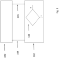
Figure 2 shows a logic diagram of a method for controlling a parking brake of a work vehicle according to an embodiment of the present invention. - The present invention will now be described with reference to particular embodiments, as illustrated in the appended drawings. However, the present invention is not limited to the particular embodiments described in the following detailed description and shown in the figures, rather the embodiments described are merely non-limiting examples of the various aspects of the present invention, whose object is defined by the claims. Further modifications and variations of the present invention will be clear to a person skilled in the art.
- In the present description, the term 'vehicle' means any mechanical vehicle driven by humans (or remotecontrolled vehicle) used to transport people, animals, or objects, whether usable on or off the roads, such as, for example, on construction sites or in quarries or mines, etc. Therefore, one example of a vehicle may be, for example, a construction machine such as a wheel tractor-scraper. In general, 'vehicle' means any means capable of moving from one location to another.
- As shown in
Figure 1 , a propulsion element 1 of a commonly known work vehicle has adrive machine 2 consisting of an internal combustion engine, such as a diesel engine, and ahydrostatic transmission 4. Thehydrostatic transmission 4 has a first hydraulic machine 8, consisting of an axial piston pump in the inclined plate structure, which is in fluid communication, by means of twowork lines hydraulic machine 14 consisting of an axial piston motor within the inclined axis structure, in a closed hydraulic circuit. It is clear that the present invention can also be made in a swashplate piston engine or a radial piston engine. The first hydraulic machine 8 is coupled to thedrive machine 2 by means of atransmission shaft 16. Atransmission shaft 18 of the secondhydraulic machine 14 is coupled to an output (not shown) of the propulsion element 1. In the particular example shown, bothhydraulic machines 8, 14 feature an adjustable displacement volume. They are configured so as to be able to work in all four quadrants, in both torque directions, both as a hydraulic pump and as a hydraulic motor. However, the present invention could clearly also work if the motor driving the gearbox were a fixed-displacement motor (i.e. having a fixed displacement volume). - The
hydrostatic transmission 4 also features acontrol device 20, in particular for controlling the torque of thedrive shaft 18. As regards signals, afirst adjustment device 22 for adjusting the first hydraulic machine 8 is connected to thecontrol device 20, which is designed to adjust the first displacement volume, and asecond adjusting device 24 for the secondhydraulic machine 14 is designed to adjust the second displacement volume. - The
hydrostatic transmission 4 has speed (rpm)sensor 26, by means of which the first speed of the first hydraulic machine 8 can be measured. Thespeed sensor 26 is connected, as regards signals, to thecontrol device 20 by means of thesignal line 28. Alternatively, the speed may also be measured from the speed of thedrive machine 2 via a CAN bus connection. In addition, thetransmission 4 features atemperature sensor 30 designed to measure a temperature of the pressure medium and any leakage current in the first hydraulic machine 8. The latter is connected, as regards signals, to thecontrol device 20 by means of asignal line 32. - Theoretically, downstream of the
hydrostatic transmission 4 there can be a multi-stage mechanical transmission connected so that the system can provide a higher speed range than the propulsion element 1. - In the case of the example shown, the second displacement volume is adjusted by means of the
adjustment device 24 electro-proportionally. For this purpose, theadjustment device 24 features a hydraulic positioning cylinder (not shown), whose reciprocally active pressure chambers can be respectively supplied with a pressure medium, via a pressure regulating valve (not shown), which can be adjusted electro-proportionally. The electro-proportional regulation results in continuous adjustment of the displacement volume. The adjustment is therefore proportional to a reference value signal coming from thecontrol device 20 via thesignal line 34. The advantage of said control concept for the secondhydraulic machine 14 lies in the fact that the second effective displacement volume essentially corresponds to the reference value of the secondhydraulic machine 14 required by thecontrol device 20. - The
work lines valves 36 with an anticavitation function. The first hydraulic machine 8 furthermore features a control pressure connection G, to which constant control pressure is applied. - The
adjustment device 22 for the first hydraulic machine 8 features apressure reduction valve 38. The latter may be connected, by means of a 4/3-way switching valve 40, to a pressure medium chamber of apositioning cylinder 42 , whose piston 44 is coupled to a swashplate in the first hydraulic machine 8 for adjusting the first displacement volume. - The
pressure reduction valve 38 is connected, as regards signals, to thecontrol device 20 by means of asignal line 46. The control pressure supplied by the connection G is present due to acontrol pressure line 48, connected to acontrol pressure input 50 of thepressure reducing valve 38. - A valve body of the
pressure reduction valve 38 is pre-tensioned, by means of a spring, into a final position, in which a control pressure output 52 of thepressure reduction valve 38 forms a connection with a tank T by means of a pressure medium. Anelectromagnet 54, which can be powered by means of thesignal line 46, counters the force of the spring. - If powered, the valve body of the
pressure reducing valve 38 moves from the aforesaid final position (connection of the control pressure output 52 with the tank T) to intermediate positions, in which the other final position has an increasing inflow which releases the fluid connection between thecontrol pressure inlet 50 and the control pressure output 52. Consequently, as the power supply to theelectromagnet 54 increases, the control pressure at the control pressure output 52 increases. The control pressure output 52 is connected, via a control pressure line, to the 4/3-way switching valve 40. Depending on theswitching position positioning cylinder 42. The 4/3way switching valve 40 acts as a travel direction valve. - Clearly, the method for adjusting the first hydraulic machine 8 described above is in no way binding and, as will also become clear in the description that follows, the present invention may be applied to any system for controlling the first hydraulic machine, for example to a first hydraulic machine with a hydraulic or electro-hydraulic pump drive, with or without feedback, with or without position sensors.
- With reference to
Figure 2 , the method for controlling a parking brake of a vehicle comprising a propulsion element 1, such as that shown inFigure 1 , will now be explained in detail. - In one
state 100, the vehicle parking brake is applied and the vehicle is in a parked state. In this state, the value of a variable which depends on the upstream and downstream pressure difference of the said secondhydraulic machine 14 is saved before the vehicle has stopped completely and therefore reached the stationary state. - This variable could be the said pressure itself or the torque produced by the said second
hydraulic machine 14 before the machine is stopped by means of the parking brake. In this case, the torque is calculated as follows:
- Where TLoad is the torque of the second
hydraulic machine 14, VgMot is the displacement of the secondhydraulic machine 14, Δp is the difference between the pressure up and downstream of the second hydraulic machine while r G is the gear ratio. The advantage of this variable is that the logic still applies even if the gear ratio is different when the vehicle is stationary or in the event that the displacement of the secondhydraulic machine 14 is different. Indeed, as will become clearer later in the description, this variable is measured before re-starting and, in the event that a different gear has been engaged, the new gear ratio will be considered in the calculation of the new torque. If this variable is chosen, in addition to the difference in pressure up and downstream of the secondhydraulic machine 14, the displacement of the secondhydraulic machine 14 must also clearly be measured. - Alternatively, if for example the pressure and the flow rate were measured when the vehicle was not yet stationary, this variable could be the torque produced by the second
hydraulic machine 14 minus the torque due to the acceleration of the said vehicle. In this case, the torque is calculated as follows:
- Where TLoad is the torque of the second
hydraulic machine 14, VgMot is the displacement of the secondhydraulic machine 14, Δp is the difference between the pressure up and downstream of the second hydraulic machine, r G is the gear ratio, and av is the vehicle's acceleration while mV is the mass of the said vehicle. This variable has the advantage of also considering the part of the torque due to the acceleration of the vehicle and therefore obtaining a torque due solely to the external load (the condition of the ground where the vehicle is parked and the weight of the said vehicle). - If the vehicle receives a request to release the parking brake, for example by means of an operator, the vehicle switches to state 102 (as shown by arrow 101). In
state 102, the hydraulic transmission is checked and controlled and the parking brake is released only if the check in 103 (which will be described in detail in the following paragraph) has given a positive result. However, there are conditions, which will be described later, in which the check on this variable does not have to be performed as it is unnecessary and it is possible to proceed by directly releasing the parking brake. - Indeed, this check on this variable only occurs in the following two cases:
- If the vehicle is parked facing upwards on a vertical slope and there is a request to release the parking brake in order to drive forwards, up the said slope;
- If the vehicle is parked facing downwards on a vertical slope and there is a request to release the parking brake in order to reverse, to drive up the said slope;
- If the circumstances do not fall under either of these two cases, the operator may release the parking brake directly. Therefore, if it is found, in
state 102, that one of the following two situations listed below has occurred, the parking brake is released immediately: - If the vehicle is parked facing upwards on a vertical slope and there is a request to release the parking brake in order to reverse, down the said slope;
- If the vehicle is parked facing downwards on a vertical slope and there is a request to release the parking brake in order to move forwards, down the said slope.
- The detection of whether the said vehicle is facing upwards or downwards is performed by reading whether the pressure difference up and downstream of the said second
hydraulic machine 14 is positive or negative. Alternatively, this may be established using means configured to measure the gradient of the ground along which the said vehicle is parked. - If the check on this variable must be carried out, the current absolute value of the variable described above is measured (or calculated in the case of the torque) and compared with the absolute value of the same variable in
state 100. If the value is greater, then the parking brake can be released. If this state has not yet occurred, the check on the variable is repeated until this state occurs and it is therefore possible to release the parking brake and return fromstate 104 tostate 100 until a new command to engage the parking brake is received. - The following paragraphs will describe four situations in which this vehicle may find itself in and how the method described above is applied in each of these situations.
- The first two situations arise in the event that the vehicle is stopped while being driven upwards and the driving brake is engaged.
- If the operator requires the vehicle to be moved in the opposite direction to the direction of travel prior to stopping, the parking brake will be released immediately.
- If, on the other hand, the operator requires the vehicle to be driven in the same direction as it had been travelling prior to stopping, the check described above takes place. The current value of one of the pressure-dependent quantities is compared with the absolute value of the same variable before the vehicle was stopped. If the current value is greater than or equal to the value from before the vehicle was stopped, then the parking brake can be released. If, on the other hand, the current value is lower, the check will be repeated until this condition is met and the parking brake can be released.
- The other two situations arise in the event that the vehicle is stopped while being driven downwards and the driving brake is engaged.
- If the operator requires the vehicle to move in the same direction as it was travelling prior to stopping, the parking brake will be released immediately.
- If, on the other hand, the operator requires the vehicle to move in the opposite direction to the direction of travel prior to stopping, the check described above takes place. The current value of one of the pressure-dependent quantities is compared with the absolute value of the same variable before the vehicle was stopped. If the current value is greater than or equal to the value from before the vehicle was stopped, then the parking brake can be released. If, on the other hand, the current value is lower, the check will be repeated until this condition is met and the parking brake can be released.
- Although the present invention has been described with reference to the embodiments described above, it is clear to a person skilled in the art that various modifications, variations and improvements may be made to the present invention based on the teachings set out above and remaining within the scope of the annexed claims, without departing from the object and scope of the invention.
- Finally, those areas that are considered known to a person skilled in the art have not been described in order not to unnecessarily overshadow the invention described.
- Consequently, the invention is not limited to merely the embodiments described above, but only by the scope of the annexed claims.
Claims (11)
- A method of controlling a parking brake of a vehicle, said vehicle comprising a drive machine (2), a first hydraulic machine (8) and a second hydraulic machine (14), said drive machine (2) being configured to drive said first hydraulic machine (8), said first hydraulic machine (8) having a first displacement volume, and said second hydraulic machine (14) having a second displacement volume being arranged in hydraulic connection with said first hydraulic machine (8) and being configured to be coupled to drive means of said vehicle, which are configured to provide a movement of said vehicle, said method being characterized in that:
Prior to a release of said parking brake a variable dependent on a pressure difference between upstream and downstream of said second hydraulic machine (14) is compared with the same variable measured prior to an engagement of said parking brake, wherein said parking brake is released if the absolute value of said variable measured prior to release of said parking brake is greater than the absolute value of the same variable measured prior to engagement of said parking brake. - Method according to claim 1 wherein said variable is the absolute value of the pressure realized by said first hydraulic machine (8).
- Method according to claim 1 wherein said variable corresponds to the torque of said second hydraulic machine (14), wherein said torque is calculated after measuring said pressure difference between upstream and downstream of said second hydraulic machine
(14) and preferably the displacement volume of said second hydraulic machine (8). - Method according to claim 1, wherein said variable corresponds to the torque of said second hydraulic machine (14), wherein said torque is calculated after measuring said pressure difference between upstream and downstream of said second hydraulic machine
(14) and preferably the displacement volume of said second hydraulic machine (8), from which the torque due to the acceleration of the vehicle is subtracted, so as to obtain a torque due to the load of said vehicle only. - Method according to any one of claims 1 to 4, wherein said comparison of said absolute value of said variable is carried out only under one of the following conditions:Where said vehicle is along an uphill slope and where there is a demand for release said parking brake to proceed forward along said slope; andWhere said vehicle is on a downhill slope and where there is a request for release of said parking brake to reverse down said slope.
- Method according to any one of claims 1 to 5, wherein said parking brake is released without performing said comparison of said absolute value of said variable under any one of the following conditions:
Where said vehicle is located along an uphill slope and where there is a demand for release of said parking brake in order to reverse along said uphill slope; and Where said vehicle is on a downhill slope and where there is a demand for release of said parking brake to proceed forward on said downhill slope. - A method according to any one of claims 5 or 6, wherein the detection of whether said vehicle is along an uphill slope or along a downhill slope is provided by means of the sign of said pressure difference between upstream and downstream of said second hydraulic machine (14).
- A method according to any one of claims 5 or 6, wherein the detection of whether said vehicle is along an uphill slope or along a downhill slope is provided by means of detection means configured to detect the slope of the ground along which said vehicle is stationed.
- Method according to any one of claims 1 to 8, wherein said method comprises the following steps:a. Receiving a command to engage said parking brake in said vehicle;b. Measuring a pressure difference between upstream and downstream of said second hydraulic machine (14) and preferably the displacement volume of said second hydraulic machine (14);c. Engaging said parking brake;d. Receiving a command to release said parking brake;e. Releasing said parking brake if the absolute value of said variable measured prior to release of said parking brake is greater than the absolute value of the same variable measured prior to engagement of said parking brake.
- A method according to any one of claims 1 to 9, wherein said vehicle is a mobile operating machine.
- Method according to any one of claims 1 to 10, wherein said first displacement volume of said first hydraulic machine (8) is configured to be adjusted and wherein preferably said second displacement volume of said second hydraulic machine (14) can be adjusted.
Applications Claiming Priority (1)
| Application Number | Priority Date | Filing Date | Title |
|---|---|---|---|
| IT102021000001601A IT202100001601A1 (en) | 2021-01-27 | 2021-01-27 | METHOD OF CHECKING A PARKING BRAKE OF A VEHICLE |
Publications (2)
| Publication Number | Publication Date |
|---|---|
| EP4035957A1 EP4035957A1 (en) | 2022-08-03 |
| EP4035957B1 true EP4035957B1 (en) | 2023-09-06 |
Family
ID=75439262
Family Applications (1)
| Application Number | Title | Priority Date | Filing Date |
|---|---|---|---|
| EP22152609.8A Active EP4035957B1 (en) | 2021-01-27 | 2022-01-21 | Method of controlling a parking brake of a vehicle |
Country Status (2)
| Country | Link |
|---|---|
| EP (1) | EP4035957B1 (en) |
| IT (1) | IT202100001601A1 (en) |
Family Cites Families (2)
| Publication number | Priority date | Publication date | Assignee | Title |
|---|---|---|---|---|
| DE102011008707B4 (en) * | 2011-01-17 | 2024-11-21 | Linde Material Handling Gmbh | Mobile work machine, especially industrial truck |
| EP2748491B1 (en) * | 2011-08-25 | 2018-02-07 | CNH Industrial Italia S.p.A. | Proportional parking brake control in cooperation with operation of a continuously variable transmission |
-
2021
- 2021-01-27 IT IT102021000001601A patent/IT202100001601A1/en unknown
-
2022
- 2022-01-21 EP EP22152609.8A patent/EP4035957B1/en active Active
Also Published As
| Publication number | Publication date |
|---|---|
| IT202100001601A1 (en) | 2022-07-27 |
| EP4035957A1 (en) | 2022-08-03 |
Similar Documents
| Publication | Publication Date | Title |
|---|---|---|
| US7926267B2 (en) | Hystat transmission having pressure override control | |
| EP2802529B1 (en) | Method for obtaining a full range of lift speeds using a single input | |
| US7856817B2 (en) | Hydraulic drive system | |
| EP2687704B1 (en) | Drive control device for work vehicle | |
| CA2605049C (en) | Anti-overspeed system for vehicle and associated method | |
| JP5092059B1 (en) | Work vehicle and control method of work vehicle | |
| US20100024412A1 (en) | Control Apparatus for Working Vehicle | |
| US10071719B2 (en) | Hydrostatic traction drive in closed hydraulic circuit and method for controlling the hydrostatic traction drive | |
| EP2589836A1 (en) | Travel control apparatus for working vehicle | |
| AU2021311138B2 (en) | Hydraulic retarding control system | |
| EP0589870A1 (en) | ELECTROHYDRAULIC CONTROL UNIT FOR A DRIVELINE OF A VEHICLE. | |
| AU2009285867A1 (en) | Control system and method for braking a hydrostatic drive machine | |
| CN103790876B (en) | A kind of Closed circuit hydraulic transmission system | |
| EP1979220B1 (en) | Control system for frame-steering of a vehicle and method for controlling two steering cylinders in a frame-steered vehicle | |
| US8918258B2 (en) | System and method for avoiding engine underspeed and stall | |
| KR20050098301A (en) | Drive train for a mobile vehicle | |
| EP4035957B1 (en) | Method of controlling a parking brake of a vehicle | |
| GB2275761A (en) | Improvements in braking vehicles with hydrostatic drive | |
| EP3868620B1 (en) | Vehicle propelled with a hydrostatic drive unit and braking method | |
| CN101500836A (en) | Vehicle driveline with hydraulic power assist | |
| JP2835996B2 (en) | Industrial vehicle cargo handling and travel control device | |
| JP2006521512A (en) | How to operate the power transmission system | |
| CN203717499U (en) | Closed type hydraulic transmission system | |
| CN219115419U (en) | Hydraulic auxiliary braking system for engineering machinery and engineering machinery | |
| EP4299953B1 (en) | Method and control system of a hydraulic transmission of a work or agricultural vehicle |
Legal Events
| Date | Code | Title | Description |
|---|---|---|---|
| PUAI | Public reference made under article 153(3) epc to a published international application that has entered the european phase |
Free format text: ORIGINAL CODE: 0009012 |
|
| STAA | Information on the status of an ep patent application or granted ep patent |
Free format text: STATUS: THE APPLICATION HAS BEEN PUBLISHED |
|
| AK | Designated contracting states |
Kind code of ref document: A1 Designated state(s): AL AT BE BG CH CY CZ DE DK EE ES FI FR GB GR HR HU IE IS IT LI LT LU LV MC MK MT NL NO PL PT RO RS SE SI SK SM TR |
|
| STAA | Information on the status of an ep patent application or granted ep patent |
Free format text: STATUS: REQUEST FOR EXAMINATION WAS MADE |
|
| 17P | Request for examination filed |
Effective date: 20230203 |
|
| RBV | Designated contracting states (corrected) |
Designated state(s): AL AT BE BG CH CY CZ DE DK EE ES FI FR GB GR HR HU IE IS IT LI LT LU LV MC MK MT NL NO PL PT RO RS SE SI SK SM TR |
|
| GRAP | Despatch of communication of intention to grant a patent |
Free format text: ORIGINAL CODE: EPIDOSNIGR1 |
|
| STAA | Information on the status of an ep patent application or granted ep patent |
Free format text: STATUS: GRANT OF PATENT IS INTENDED |
|
| INTG | Intention to grant announced |
Effective date: 20230602 |
|
| GRAS | Grant fee paid |
Free format text: ORIGINAL CODE: EPIDOSNIGR3 |
|
| GRAA | (expected) grant |
Free format text: ORIGINAL CODE: 0009210 |
|
| STAA | Information on the status of an ep patent application or granted ep patent |
Free format text: STATUS: THE PATENT HAS BEEN GRANTED |
|
| AK | Designated contracting states |
Kind code of ref document: B1 Designated state(s): AL AT BE BG CH CY CZ DE DK EE ES FI FR GB GR HR HU IE IS IT LI LT LU LV MC MK MT NL NO PL PT RO RS SE SI SK SM TR |
|
| REG | Reference to a national code |
Ref country code: GB Ref legal event code: FG4D |
|
| REG | Reference to a national code |
Ref country code: CH Ref legal event code: EP |
|
| REG | Reference to a national code |
Ref country code: DE Ref legal event code: R096 Ref document number: 602022000424 Country of ref document: DE |
|
| REG | Reference to a national code |
Ref country code: IE Ref legal event code: FG4D |
|
| REG | Reference to a national code |
Ref country code: LT Ref legal event code: MG9D |
|
| REG | Reference to a national code |
Ref country code: NL Ref legal event code: MP Effective date: 20230906 |
|
| PG25 | Lapsed in a contracting state [announced via postgrant information from national office to epo] |
Ref country code: GR Free format text: LAPSE BECAUSE OF FAILURE TO SUBMIT A TRANSLATION OF THE DESCRIPTION OR TO PAY THE FEE WITHIN THE PRESCRIBED TIME-LIMIT Effective date: 20231207 |
|
| PG25 | Lapsed in a contracting state [announced via postgrant information from national office to epo] |
Ref country code: SE Free format text: LAPSE BECAUSE OF FAILURE TO SUBMIT A TRANSLATION OF THE DESCRIPTION OR TO PAY THE FEE WITHIN THE PRESCRIBED TIME-LIMIT Effective date: 20230906 Ref country code: RS Free format text: LAPSE BECAUSE OF FAILURE TO SUBMIT A TRANSLATION OF THE DESCRIPTION OR TO PAY THE FEE WITHIN THE PRESCRIBED TIME-LIMIT Effective date: 20230906 Ref country code: NO Free format text: LAPSE BECAUSE OF FAILURE TO SUBMIT A TRANSLATION OF THE DESCRIPTION OR TO PAY THE FEE WITHIN THE PRESCRIBED TIME-LIMIT Effective date: 20231206 Ref country code: LV Free format text: LAPSE BECAUSE OF FAILURE TO SUBMIT A TRANSLATION OF THE DESCRIPTION OR TO PAY THE FEE WITHIN THE PRESCRIBED TIME-LIMIT Effective date: 20230906 Ref country code: LT Free format text: LAPSE BECAUSE OF FAILURE TO SUBMIT A TRANSLATION OF THE DESCRIPTION OR TO PAY THE FEE WITHIN THE PRESCRIBED TIME-LIMIT Effective date: 20230906 Ref country code: HR Free format text: LAPSE BECAUSE OF FAILURE TO SUBMIT A TRANSLATION OF THE DESCRIPTION OR TO PAY THE FEE WITHIN THE PRESCRIBED TIME-LIMIT Effective date: 20230906 Ref country code: GR Free format text: LAPSE BECAUSE OF FAILURE TO SUBMIT A TRANSLATION OF THE DESCRIPTION OR TO PAY THE FEE WITHIN THE PRESCRIBED TIME-LIMIT Effective date: 20231207 Ref country code: FI Free format text: LAPSE BECAUSE OF FAILURE TO SUBMIT A TRANSLATION OF THE DESCRIPTION OR TO PAY THE FEE WITHIN THE PRESCRIBED TIME-LIMIT Effective date: 20230906 |
|
| REG | Reference to a national code |
Ref country code: AT Ref legal event code: MK05 Ref document number: 1608159 Country of ref document: AT Kind code of ref document: T Effective date: 20230906 |
|
| PG25 | Lapsed in a contracting state [announced via postgrant information from national office to epo] |
Ref country code: NL Free format text: LAPSE BECAUSE OF FAILURE TO SUBMIT A TRANSLATION OF THE DESCRIPTION OR TO PAY THE FEE WITHIN THE PRESCRIBED TIME-LIMIT Effective date: 20230906 |
|
| PG25 | Lapsed in a contracting state [announced via postgrant information from national office to epo] |
Ref country code: IS Free format text: LAPSE BECAUSE OF FAILURE TO SUBMIT A TRANSLATION OF THE DESCRIPTION OR TO PAY THE FEE WITHIN THE PRESCRIBED TIME-LIMIT Effective date: 20240106 |
|
| PG25 | Lapsed in a contracting state [announced via postgrant information from national office to epo] |
Ref country code: AT Free format text: LAPSE BECAUSE OF FAILURE TO SUBMIT A TRANSLATION OF THE DESCRIPTION OR TO PAY THE FEE WITHIN THE PRESCRIBED TIME-LIMIT Effective date: 20230906 |
|
| PG25 | Lapsed in a contracting state [announced via postgrant information from national office to epo] |
Ref country code: ES Free format text: LAPSE BECAUSE OF FAILURE TO SUBMIT A TRANSLATION OF THE DESCRIPTION OR TO PAY THE FEE WITHIN THE PRESCRIBED TIME-LIMIT Effective date: 20230906 |
|
| PG25 | Lapsed in a contracting state [announced via postgrant information from national office to epo] |
Ref country code: SM Free format text: LAPSE BECAUSE OF FAILURE TO SUBMIT A TRANSLATION OF THE DESCRIPTION OR TO PAY THE FEE WITHIN THE PRESCRIBED TIME-LIMIT Effective date: 20230906 Ref country code: RO Free format text: LAPSE BECAUSE OF FAILURE TO SUBMIT A TRANSLATION OF THE DESCRIPTION OR TO PAY THE FEE WITHIN THE PRESCRIBED TIME-LIMIT Effective date: 20230906 Ref country code: IS Free format text: LAPSE BECAUSE OF FAILURE TO SUBMIT A TRANSLATION OF THE DESCRIPTION OR TO PAY THE FEE WITHIN THE PRESCRIBED TIME-LIMIT Effective date: 20240106 Ref country code: ES Free format text: LAPSE BECAUSE OF FAILURE TO SUBMIT A TRANSLATION OF THE DESCRIPTION OR TO PAY THE FEE WITHIN THE PRESCRIBED TIME-LIMIT Effective date: 20230906 Ref country code: EE Free format text: LAPSE BECAUSE OF FAILURE TO SUBMIT A TRANSLATION OF THE DESCRIPTION OR TO PAY THE FEE WITHIN THE PRESCRIBED TIME-LIMIT Effective date: 20230906 Ref country code: CZ Free format text: LAPSE BECAUSE OF FAILURE TO SUBMIT A TRANSLATION OF THE DESCRIPTION OR TO PAY THE FEE WITHIN THE PRESCRIBED TIME-LIMIT Effective date: 20230906 Ref country code: AT Free format text: LAPSE BECAUSE OF FAILURE TO SUBMIT A TRANSLATION OF THE DESCRIPTION OR TO PAY THE FEE WITHIN THE PRESCRIBED TIME-LIMIT Effective date: 20230906 Ref country code: PT Free format text: LAPSE BECAUSE OF FAILURE TO SUBMIT A TRANSLATION OF THE DESCRIPTION OR TO PAY THE FEE WITHIN THE PRESCRIBED TIME-LIMIT Effective date: 20240108 Ref country code: SK Free format text: LAPSE BECAUSE OF FAILURE TO SUBMIT A TRANSLATION OF THE DESCRIPTION OR TO PAY THE FEE WITHIN THE PRESCRIBED TIME-LIMIT Effective date: 20230906 |
|
| PG25 | Lapsed in a contracting state [announced via postgrant information from national office to epo] |
Ref country code: PL Free format text: LAPSE BECAUSE OF FAILURE TO SUBMIT A TRANSLATION OF THE DESCRIPTION OR TO PAY THE FEE WITHIN THE PRESCRIBED TIME-LIMIT Effective date: 20230906 |
|
| REG | Reference to a national code |
Ref country code: DE Ref legal event code: R097 Ref document number: 602022000424 Country of ref document: DE |
|
| PG25 | Lapsed in a contracting state [announced via postgrant information from national office to epo] |
Ref country code: DK Free format text: LAPSE BECAUSE OF FAILURE TO SUBMIT A TRANSLATION OF THE DESCRIPTION OR TO PAY THE FEE WITHIN THE PRESCRIBED TIME-LIMIT Effective date: 20230906 |
|
| PLBE | No opposition filed within time limit |
Free format text: ORIGINAL CODE: 0009261 |
|
| STAA | Information on the status of an ep patent application or granted ep patent |
Free format text: STATUS: NO OPPOSITION FILED WITHIN TIME LIMIT |
|
| PG25 | Lapsed in a contracting state [announced via postgrant information from national office to epo] |
Ref country code: DK Free format text: LAPSE BECAUSE OF FAILURE TO SUBMIT A TRANSLATION OF THE DESCRIPTION OR TO PAY THE FEE WITHIN THE PRESCRIBED TIME-LIMIT Effective date: 20230906 Ref country code: SI Free format text: LAPSE BECAUSE OF FAILURE TO SUBMIT A TRANSLATION OF THE DESCRIPTION OR TO PAY THE FEE WITHIN THE PRESCRIBED TIME-LIMIT Effective date: 20230906 |
|
| 26N | No opposition filed |
Effective date: 20240607 |
|
| PG25 | Lapsed in a contracting state [announced via postgrant information from national office to epo] |
Ref country code: MC Free format text: LAPSE BECAUSE OF FAILURE TO SUBMIT A TRANSLATION OF THE DESCRIPTION OR TO PAY THE FEE WITHIN THE PRESCRIBED TIME-LIMIT Effective date: 20230906 |
|
| PG25 | Lapsed in a contracting state [announced via postgrant information from national office to epo] |
Ref country code: MC Free format text: LAPSE BECAUSE OF FAILURE TO SUBMIT A TRANSLATION OF THE DESCRIPTION OR TO PAY THE FEE WITHIN THE PRESCRIBED TIME-LIMIT Effective date: 20230906 |
|
| PG25 | Lapsed in a contracting state [announced via postgrant information from national office to epo] |
Ref country code: LU Free format text: LAPSE BECAUSE OF NON-PAYMENT OF DUE FEES Effective date: 20240121 |
|
| PG25 | Lapsed in a contracting state [announced via postgrant information from national office to epo] |
Ref country code: LU Free format text: LAPSE BECAUSE OF NON-PAYMENT OF DUE FEES Effective date: 20240121 |
|
| PG25 | Lapsed in a contracting state [announced via postgrant information from national office to epo] |
Ref country code: BE Free format text: LAPSE BECAUSE OF NON-PAYMENT OF DUE FEES Effective date: 20240131 |
|
| PG25 | Lapsed in a contracting state [announced via postgrant information from national office to epo] |
Ref country code: FR Free format text: LAPSE BECAUSE OF NON-PAYMENT OF DUE FEES Effective date: 20240131 |
|
| PG25 | Lapsed in a contracting state [announced via postgrant information from national office to epo] |
Ref country code: FR Free format text: LAPSE BECAUSE OF NON-PAYMENT OF DUE FEES Effective date: 20240131 Ref country code: BE Free format text: LAPSE BECAUSE OF NON-PAYMENT OF DUE FEES Effective date: 20240131 |
|
| REG | Reference to a national code |
Ref country code: BE Ref legal event code: MM Effective date: 20240131 |
|
| PG25 | Lapsed in a contracting state [announced via postgrant information from national office to epo] |
Ref country code: BG Free format text: LAPSE BECAUSE OF FAILURE TO SUBMIT A TRANSLATION OF THE DESCRIPTION OR TO PAY THE FEE WITHIN THE PRESCRIBED TIME-LIMIT Effective date: 20230906 |
|
| PG25 | Lapsed in a contracting state [announced via postgrant information from national office to epo] |
Ref country code: BG Free format text: LAPSE BECAUSE OF FAILURE TO SUBMIT A TRANSLATION OF THE DESCRIPTION OR TO PAY THE FEE WITHIN THE PRESCRIBED TIME-LIMIT Effective date: 20230906 |
|
| PG25 | Lapsed in a contracting state [announced via postgrant information from national office to epo] |
Ref country code: IE Free format text: LAPSE BECAUSE OF NON-PAYMENT OF DUE FEES Effective date: 20240121 |
|
| PG25 | Lapsed in a contracting state [announced via postgrant information from national office to epo] |
Ref country code: IE Free format text: LAPSE BECAUSE OF NON-PAYMENT OF DUE FEES Effective date: 20240121 |
|
| PG25 | Lapsed in a contracting state [announced via postgrant information from national office to epo] |
Ref country code: CY Free format text: LAPSE BECAUSE OF FAILURE TO SUBMIT A TRANSLATION OF THE DESCRIPTION OR TO PAY THE FEE WITHIN THE PRESCRIBED TIME-LIMIT; INVALID AB INITIO Effective date: 20220121 |
|
| REG | Reference to a national code |
Ref country code: CH Ref legal event code: PL |
|
| PG25 | Lapsed in a contracting state [announced via postgrant information from national office to epo] |
Ref country code: CH Free format text: LAPSE BECAUSE OF NON-PAYMENT OF DUE FEES Effective date: 20250131 |
|
| PG25 | Lapsed in a contracting state [announced via postgrant information from national office to epo] |
Ref country code: TR Free format text: LAPSE BECAUSE OF FAILURE TO SUBMIT A TRANSLATION OF THE DESCRIPTION OR TO PAY THE FEE WITHIN THE PRESCRIBED TIME-LIMIT Effective date: 20230906 |
|
| PGFP | Annual fee paid to national office [announced via postgrant information from national office to epo] |
Ref country code: DE Payment date: 20260319 Year of fee payment: 5 |
|
| PGFP | Annual fee paid to national office [announced via postgrant information from national office to epo] |
Ref country code: IT Payment date: 20260130 Year of fee payment: 5 |