EP4035955A1 - Side airbag device - Google Patents
Side airbag device Download PDFInfo
- Publication number
- EP4035955A1 EP4035955A1 EP22153491.0A EP22153491A EP4035955A1 EP 4035955 A1 EP4035955 A1 EP 4035955A1 EP 22153491 A EP22153491 A EP 22153491A EP 4035955 A1 EP4035955 A1 EP 4035955A1
- Authority
- EP
- European Patent Office
- Prior art keywords
- region
- skeletal
- airbag cushion
- end side
- main chamber
- Prior art date
- Legal status (The legal status is an assumption and is not a legal conclusion. Google has not performed a legal analysis and makes no representation as to the accuracy of the status listed.)
- Granted
Links
Images









Classifications
-
- B—PERFORMING OPERATIONS; TRANSPORTING
- B60—VEHICLES IN GENERAL
- B60R—VEHICLES, VEHICLE FITTINGS, OR VEHICLE PARTS, NOT OTHERWISE PROVIDED FOR
- B60R21/00—Arrangements or fittings on vehicles for protecting or preventing injuries to occupants or pedestrians in case of accidents or other traffic risks
- B60R21/02—Occupant safety arrangements or fittings, e.g. crash pads
- B60R21/16—Inflatable occupant restraints or confinements designed to inflate upon impact or impending impact, e.g. air bags
- B60R21/23—Inflatable members
- B60R21/231—Inflatable members characterised by their shape, construction or spatial configuration
- B60R21/23138—Inflatable members characterised by their shape, construction or spatial configuration specially adapted for side protection
-
- B—PERFORMING OPERATIONS; TRANSPORTING
- B60—VEHICLES IN GENERAL
- B60R—VEHICLES, VEHICLE FITTINGS, OR VEHICLE PARTS, NOT OTHERWISE PROVIDED FOR
- B60R21/00—Arrangements or fittings on vehicles for protecting or preventing injuries to occupants or pedestrians in case of accidents or other traffic risks
- B60R21/02—Occupant safety arrangements or fittings, e.g. crash pads
- B60R21/16—Inflatable occupant restraints or confinements designed to inflate upon impact or impending impact, e.g. air bags
- B60R21/23—Inflatable members
- B60R21/231—Inflatable members characterised by their shape, construction or spatial configuration
- B60R21/233—Inflatable members characterised by their shape, construction or spatial configuration comprising a plurality of individual compartments; comprising two or more bag-like members, one within the other
-
- B—PERFORMING OPERATIONS; TRANSPORTING
- B60—VEHICLES IN GENERAL
- B60R—VEHICLES, VEHICLE FITTINGS, OR VEHICLE PARTS, NOT OTHERWISE PROVIDED FOR
- B60R21/00—Arrangements or fittings on vehicles for protecting or preventing injuries to occupants or pedestrians in case of accidents or other traffic risks
- B60R21/02—Occupant safety arrangements or fittings, e.g. crash pads
- B60R21/16—Inflatable occupant restraints or confinements designed to inflate upon impact or impending impact, e.g. air bags
- B60R21/23—Inflatable members
- B60R21/231—Inflatable members characterised by their shape, construction or spatial configuration
- B60R21/2334—Expansion control features
- B60R21/2346—Soft diffusers
-
- B—PERFORMING OPERATIONS; TRANSPORTING
- B60—VEHICLES IN GENERAL
- B60R—VEHICLES, VEHICLE FITTINGS, OR VEHICLE PARTS, NOT OTHERWISE PROVIDED FOR
- B60R21/00—Arrangements or fittings on vehicles for protecting or preventing injuries to occupants or pedestrians in case of accidents or other traffic risks
- B60R21/02—Occupant safety arrangements or fittings, e.g. crash pads
- B60R21/16—Inflatable occupant restraints or confinements designed to inflate upon impact or impending impact, e.g. air bags
- B60R21/23—Inflatable members
- B60R21/231—Inflatable members characterised by their shape, construction or spatial configuration
- B60R21/23138—Inflatable members characterised by their shape, construction or spatial configuration specially adapted for side protection
- B60R2021/23146—Inflatable members characterised by their shape, construction or spatial configuration specially adapted for side protection seat mounted
-
- B—PERFORMING OPERATIONS; TRANSPORTING
- B60—VEHICLES IN GENERAL
- B60R—VEHICLES, VEHICLE FITTINGS, OR VEHICLE PARTS, NOT OTHERWISE PROVIDED FOR
- B60R21/00—Arrangements or fittings on vehicles for protecting or preventing injuries to occupants or pedestrians in case of accidents or other traffic risks
- B60R21/02—Occupant safety arrangements or fittings, e.g. crash pads
- B60R21/16—Inflatable occupant restraints or confinements designed to inflate upon impact or impending impact, e.g. air bags
- B60R21/23—Inflatable members
- B60R21/231—Inflatable members characterised by their shape, construction or spatial configuration
- B60R21/233—Inflatable members characterised by their shape, construction or spatial configuration comprising a plurality of individual compartments; comprising two or more bag-like members, one within the other
- B60R2021/23324—Inner walls crating separate compartments, e.g. communicating with vents
Definitions
- the present invention relates to a side airbag device equipped in a vehicle seat.
- airbags include, for example, various forms such as: a so-called driver airbag which expands from near the center of the steering wheel of an automobile so as to protect a driver; a curtain airbag which deploys downward along an inner side of a window of an automobile so as to protect occupants during collisions in a lateral direction of the vehicle, as well as when overturning and during rollover accidents; and a side airbag stored in a side port of a seat which is deployed between the occupant and a side panel so as to protect the occupant upon impact in the lateral direction of the vehicle.
- the present invention relates to a side airbag device.
- an object of the present invention is to provide a side airbag device that contributes to stabilizing the deployment behavior and deployment shape of an airbag cushion.
- the present invention is a side airbag device housed in a vehicle seat, having: an airbag cushion that restrains an occupant by expanding and deploying; and an inflator that supplies expansion gas to the airbag cushion.
- the airbag cushion includes: an inflator housing region that houses the inflator; a main chamber region that primarily contributes to restraining an occupant; and a skeletal region that is connected to the inflator housing region and deploys in a rod shape prior to the main chamber.
- a first vent hole that discharges the expansion gas into the main chamber is formed in the skeletal region.
- the expansion gas flows from the inflator housing region into the skeletal region.
- the skeletal region deploys prior to the main chamber and deploys in a rod shape. Therefore, the rigidity of the rapidly deploying skeletal region is high, which stabilizes the deployment posture and deployment shape of the airbag cushion overall.
- a core is formed in a portion of the airbag cushion; therefore, the airbag cushion is not easily deformed when an occupant advances into the deployed airbag.
- a length in a front-rear direction and a length in a left-right width direction can be essentially the same, when the skeletal region in the deployed state is viewed in a cross section perpendicular to a longitudinal direction of the region.
- the cross section can be circular. This shape allows the expansion gas to flow smoothly through the skeletal region and the skeletal region to rapidly expand.
- ⁇ can be within a range of 0.5 to 1.5 times that of ⁇ .
- the skeletal region can be molded to generally extend in a linear manner in the longitudinal direction. By extending the skeletal region in a linear rod shape, there are no bent portions inside the skeletal region, which accelerates the development of the skeletal region.
- the inflator housing region can be configured to fit inside a side support part of the vehicle seat when the deployed airbag cushion is viewed from a side of a vehicle.
- the airbag cushion can be configured to include a rear end side (100a) extending in an up-down direction on a lower portion at the rear of the vehicle, an upper rear end side (100b) extending diagonally upward and forward from an upper end of the rear end side, a lower front end side (100d) extending diagonally upward and forward from the lower portion of the rear end side (100a), and an upper front end side (100c) extending between the upper rear end side (100b) and the lower front end side (100d).
- the inflator housing region can be demarcated by the rear end side (100a), the lower portion of the lower front end side (100d), and the lower portion of the upper rear end side (100b).
- the configuration can be such that, when the airbag cushion in the deployed state is viewed from a side of the vehicle, the upper rear end side (100b) extends between an uppermost point (HP) of the airbag cushion and an upper end of the rear end side (100a), the lower front end side
- (100d) extends between a lowermost point (LP) and frontmost point (FP) of the airbag cushion, and the upper front end side (100c) extends between the uppermost point (HP) and the frontmost point (FP).
- a second vent hole that discharges expansion gas into the main chamber can be formed in the inflator housing region.
- the skeletal region can be configured to include a first region extending from an upper portion of the inflator housing region along the upper rear end side (100b), and so that the main chamber is positioned in front of the skeletal region.
- the skeletal region is positioned behind the occupant (shoulders and torso), such that the occupant moving in a lateral direction can be quickly restrained.
- the skeletal region can be configured to include a second region extending from a lower portion of the inflator housing region along the lower front end side (100d), and the main chamber is positioned behind the second region.
- the skeletal region extends greatly forward from the side support part of the vehicle seat.
- the skeletal region can be configured to include a first region extending from an upper portion of the inflator housing region along the upper rear end side (100b) and a second region extending from a lower portion of the inflator housing region along the lower front end side (100d), and the main chamber is positioned between the first region and second region.
- the skeletal region extends from a lower portion to a wide range above and in front of the airbag cushion, allowing the airbag cushion to be spread significantly at an early stage and the maximum restraining area to be quickly secured.
- the skeletal region can be configured to include a third region extending from the inflator housing region to a center position of the upper front end side (100c), and the main chamber is positioned in front of and behind the skeletal region.
- the skeletal region extends upward or diagonally upward from a periphery of the inflator through a periphery of the center of the airbag cushion.
- a baffle plate that regulates the thickness in a vehicle width direction can be provided inside the main chamber.
- the baffle plate can be configured to extend substantially parallel to the skeletal region, when the deployed airbag cushion is viewed from the vehicle width direction.
- the direction in which the occupant is facing (the direction of vehicle travel) when the occupant is seated in the seat in a normal posture is referred to as “forward” and the opposite direction is referred to as “rear”, and the axis of the coordinates are referred to as the "front-rear direction”.
- the right of the occupant is referred to as the "right direction”
- the left of the occupant is referred to as the "left direction”
- the direction indicating the coordinate axis is referred to as the "left and right direction.”
- a region on an occupant side from a side frame of the seat shall be referred to as "inside”
- a region opposite from the occupant as viewed from the side frame shall be referred to as "outside”.
- the head direction of the occupant is referred to as "up”
- the waist direction of the occupant is referred to as "down”
- the direction indicating the coordinate axis is referred to as the "vertical direction.”
- the side airbag apparatus includes a type which is deployed on the door side of (outside) the seat, along with a type which is deployed on the vehicle center side of the seat.
- a side airbag device of a type which is deployed on the vehicle center side of the seat, for example, is referred to as a far side airbag, front center airbag, rear center airbag, and the like.
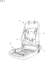
- FIG. 1 is a perspective view primarily illustrating an external shape of a vehicle seat according to the present invention, with an illustration of an airbag device (airbag module) 20 omitted.
- FIG. 2 is a perspective view illustrating an internal structure (seat frame) functioning as a framework of the vehicle seat illustrated in FIG. 1 , with an illustration of the airbag device (airbag module) 20 omitted herein as well.
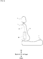
- FIG. 3 is a schematic side surface view of the vehicle seat according to the present invention, illustrating a condition where the airbag device (airbag module) 20 is stowed on a side surface (near side) near a left side seat door as observed from the outside in the vehicle width direction.
- FIG. 4 is a schematic side view of the vehicle seat according to the present invention, illustrating a condition where the airbag cushion is deployed as observed from the outer side in the vehicle width direction.
- the vehicle seat in the present embodiment when viewed as a part, is composed of a seat cushion 2 of a portion in which an occupant is seated; a seat back 1 forming a backrest; and a headrest 3 connected to the upper end of the seat back 1.
- a seat back frame 1f forming a skeleton of the seat is provided inside the seat back 1, a pad (not shown) made of a urethane foam material or the like is provided on a surface and periphery thereof, and a surface of the pad is covered with a skin such as leather, fabric, or the like.
- a seating frame 2f is provided on a bottom side of the seat cushion 2. Similar to the seat back 1, a pad made of a urethane foam material or the like is provided on an upper surface and periphery thereof, and a surface of the pad is covered by the skin such as leather, fabric, or the like.
- the seating frame 2f and the seat back frame 1f are connected via a reclining mechanism 4.
- the seat back frame 1f is configured into a frame shape by side frames 10 disposed laterally spaced apart and extending in the vertical direction, an upper frame connecting the upper ends of the side frames 10, and a lower frame connecting the lower ends thereof.
- the headrest 3 is configured by providing a cushioned component outside a headrest frame.
- the side airbag device 20 is secured to the side frame. Furthermore, as illustrated in FIG. 4 , when the side airbag device 20 is activated, an airbag cushion 30 deploys toward the front.
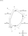
- FIG. 5 is an explanatory diagram for regulating each site of the deployed airbag cushion 30 (130, 230, 330, 430, 530, 630, 730), which can also be commonly applied to all of the embodiments described below.
- the airbag cushion 30 can be demarcated into a rear end side 100a extending in an up-down direction on a lower portion at the rear of the vehicle, an upper rear end side 100b extending diagonally upward and forward from an upper end of the rear end side 100a, a lower front end side 100d extending diagonally upward and forward from the lower portion of the rear end side 100a, and an upper front end side 100c extending between the upper rear end side 100b and the lower front end side 100d.
- the airbag cushion 30 in the deployed state viewed from a side of the vehicle
- expression is feasible where the upper rear end side 100b extends between an uppermost point HP of the airbag cushion and an upper end of the rear end side 100a
- the lower front end side 100d extends between a lowermost point LP and frontmost point FP of the airbag cushion
- the upper front end side 100c extends between the uppermost point HP and the frontmost point FP.
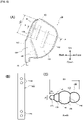
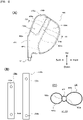
- FIG. 6 illustrates a configuration of a side airbag device according to Embodiment 1 of the present invention, where (A) is a side view of a deployed airbag cushion 130, (B) is a plan view of a partition panel 138 disposed inside the airbag cushion 130 to form a skeletal region 136, and (C) is a schematic cross-sectional view along direction A1-A1 in (A).
- the side airbag device includes: an airbag cushion 130 that restrains an occupant when expanded and deployed; and an inflator 32 that supplies expansion gas to the airbag cushion 130.
- the airbag cushion 130 includes: an inflator housing region 134 that houses the inflator 32; a main chamber region 135 that primarily contributes to restraining an occupant; and a skeletal region 136 that is connected to the inflator housing region 134 and deploys in a rod shape prior to the main chamber 135.
- the airbag cushion 130 can be molded into a bag shape by folding one panel over along the rear end side 100a and stitching together the other sides 100b, 100c, 100d. Note that the airbag cushion 130 can also be molded into a bag shape by overlaying two panels having the same shape and stitching them together around the entire circumference.
- the skeletal region 136 is configured to extend from an upper portion of the inflator housing region 134 along the upper rear end side (100b) such that the main chamber 135 is positioned in front of the skeletal region 136.
- the skeletal region 136 is molded by stitching an edge portion in a longitudinal direction of one strip-shaped partition panel 138 with regard an inner surface of the airbag cushion 130.
- the partition panel 138 demarcates the skeletal region 136 and also forms the inflator housing region 134.
- the inflator housing region 134 which is substantially triangular in a side view, is demarcated by the rear end side (100a), the lower portion of the lower front end side (100d), the lower portion of the upper rear end side (100b), and the partition panel 138.
- the partition panel 138 when viewed as a whole, is configured such that an intermediate position is bent but extends in a linear manner in the longitudinal direction in a skeletal region 136 range (136x).
- a skeletal region 136 range 136x
- vent holes 144, 146 are formed at each of two end portions of the partition panel 138.
- the vent holes 144 connect the skeletal region 136 and the main chamber 135.
- the vent hole 146 connects the inflator housing region 134 and the main chamber 135.
- baffle plates 140, 142 that regulate the thickness in the vehicle width direction are provided inside the main chamber 135.
- the baffle plates 140, 142 are arranged and configured so as to extend essentially in parallel with the longitudinal direction of the skeletal region 136. Note that the partition panel 138 and baffle plates 140, 142 can be molded from the same material fabric as the main body portion of the airbag cushion 130.
- the skeletal region 136 when viewed in a cross-section perpendicular to the longitudinal direction, the skeletal region 136 is preferably set such that a length D1 in the front-rear direction and a length D2 in the left-right width direction are essentially the same.
- the cross section can be circular. This shape allows the expansion gas to flow smoothly through the skeletal region 136 and the skeletal region 136 to rapidly expand. Note that the shape of the skeletal region can also be similarly set in the Embodiments 2 to 7 described below.
- ⁇ can be within a range of 0.5 to 1.5 times that of ⁇ .
- the cross-sectional area of the skeletal region 136 is sufficiently small as compared to the main chamber 135.
- D1 and D2 can be approximately 1/10 to 1/5 of an overall width D0 of the airbag cushion 130.
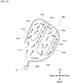
- FIG. 7 is an explanatory diagram illustrating the flow of gas inside the airbag cushion 130.
- expansion gas flows from the inflator housing region 134 to the skeletal region 136.
- the expansion gas also flows from the inflator housing region 134 to the main chamber 135 through the vent holes 146 in the partition panel 138.
- the skeletal region 136 precedes the main chamber 135 and deploys into a rod shape.
- the internal pressure in the skeletal region 136 which has a small cross-sectional area, is relatively high, and the rigidity of the skeletal region 136 increases, forming a core on an entire rear portion of the airbag cushion 130.
- the skeletal region 136 positioned behind (shoulder and torso) of the occupant can quickly restrain the occupant moving in the lateral direction and stabilize the deployment posture and deployment shape of the entire airbag cushion 130.
- the airbag cushion 130 is not easily deformed, and thus the occupant can be reliably restrained.
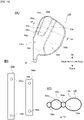
- FIG. 8 illustrates a configuration of a side airbag device according to Embodiment 2 of the present invention, where (A) is a side view of a deployed airbag cushion 230, (B) is a plan view of a partition panel 238 disposed inside the airbag cushion 230 to form a skeletal region 236, and (C) is a schematic cross-sectional view along direction A2-A2 in (A).
- the side airbag device includes: an airbag cushion 230 that restrains an occupant when expanded and deployed; and an inflator 32 that supplies expansion gas to the airbag cushion 230.
- the airbag cushion 230 includes: an inflator housing region 234 that houses the inflator 32; a main chamber region 235 that primarily contributes to restraining an occupant; and a skeletal region 236 that is connected to the inflator housing region 234 and deploys in a rod shape prior to the main chamber 235.
- the airbag cushion 230 can be molded into a bag shape by folding one panel over along the rear end side 100a and stitching together the other sides 100b, 100c, 100d. Note that the airbag cushion 230 can also be molded into a bag shape by overlaying two panels having the same shape and stitching them together around the entire circumference.
- the skeletal region 236 is configured to extend from a lower portion of the inflator housing region 234 to the lower front end side (100d) such that the main chamber 235 is positioned behind the skeletal region 236.
- the inflator housing region 234 and skeletal region 236 are molded by stitching an edge portion in a longitudinal direction of one strip-shaped partition panel 238 with regard to an inner surface of the airbag cushion 230.
- the inflator housing region 234, which is substantially triangular in side view, is demarcated by the rear end side (100a), the lower portion of the lower front end side (100d), the lower portion of the upper rear end side (100b), and the partition panel 238.
- the partition panel 238 is configured so as to generally extend in a linear manner in the longitudinal direction at a portion corresponding to the skeletal region 236.
- the expansion gas flows smoothly inside the skeletal region 236, resulting in a faster expansion rate.
- vent holes 246 are formed on a first end of the partition panel 238, and one vent hole 248 is formed on a second end.
- the vent hole 248 connects the skeletal region 136 [sic] and the main chamber 235.
- the vent hole 246 connects the inflator housing region 234 and the main chamber 235.
- a baffle plate 240 that regulates the thickness in the vehicle width direction is provided inside the main chamber 235.
- the baffle plate 240 is arranged and configured so as to extend essentially in parallel with the longitudinal direction of the skeletal region 236. Note that the partition panel 238 and baffle plate 240 can be molded from the same material fabric as the main body portion of the airbag cushion 230.
- the skeletal region 236 when viewed in a cross-section perpendicular to the longitudinal direction, is preferably set such that a length D1 in the front-rear direction and a length D2 in the left-right width direction are essentially the same.
- the cross section can be circular. This shape allows the expansion gas to flow smoothly through the skeletal region 236 and the skeletal region 236 to rapidly expand.
- ⁇ can be within a range of 0.5 to 1.5 times that of ⁇ .
- the cross-sectional area of the skeletal region 236 is sufficiently small as compared to the main chamber 235.
- D1 and D2 can be approximately 1/10 to 1/5 of an overall width D0 of the airbag cushion 230.
- FIG. 9 is an explanatory diagram illustrating the flow of gas inside the airbag cushion 230.
- expansion gas flows from the inflator housing region 234 to the skeletal region 236.
- the expansion gas also flows from the inflator housing region 234 through the vent hole 246 in the partition panel 238 to the main chamber 235.
- the skeletal region 236 precedes the main chamber 235 and deploys into a rod shape.
- the internal pressure in the skeletal region 236, which has a small cross-sectional area, is relatively high, and the rigidity of the skeletal region 236 increases, forming a core on an entire front portion of the airbag cushion 230.
- the skeletal region 236 extends greatly forward from the side support part of the vehicle seat. As a result, the deployment posture and deployment shape of the entire airbag cushion 230 is stabilized. Furthermore, when the occupant advances into the deployed airbag cushion 230, the airbag cushion 230 is not easily deformed, and thus the occupant can be reliably restrained.
- FIG. 10 illustrates a configuration of a side airbag device according to Embodiment 3 of the present invention, where (A) is a side view of a deployed airbag cushion 330, (B) is a plan view of a partition panel disposed inside the airbag cushion 330 to form a skeletal region, and (C) is a schematic cross-sectional view along direction A3-A3 in (A).
- FIG. 11 illustrates the flow of gas inside the airbag cushion in the side airbag device 330 according to Embodiment 3.
- the side airbag device combines the inventions according to Embodiments 1 and 2 described above, and includes: an airbag cushion 330 that restrains an occupant when expanded and deployed; and an inflator 32 that supplies expansion gas to the airbag cushion 330.
- the airbag cushion 330 includes: an inflator housing region 334 that houses the inflator 32; a main chamber region 335 that primarily contributes to restraining an occupant; and skeletal regions 336a, 336b that are connected to the inflator housing region 334 and deploy in a rod shape prior to the main chamber 335.
- the airbag cushion 330 can be molded into a bag shape by folding one panel over along the rear end side 100a and stitching together the other sides 100b, 100c, 100d. Note that the airbag cushion 330 can also be molded into a bag shape by overlaying two panels having the same shape and stitching them together around the entire circumference.
- the skeletal regions 336a, 336b include a first region 336a that extends from the upper portion of the inflator housing region 334 along the upper rear end side (100b) and a second region 336b that extends from the lower portion of the inflator housing region along the lower front end side (100d).
- the main chamber 335 is positioned between the first region 336a and the second region 336b.
- the inflator housing region 334 and skeletal regions 336a, 336b are molded by stitching an edge portion in a longitudinal direction of one strip-shaped partition panel 338 with regard an inner surface of the airbag cushion 330.
- the inflator housing region 334 which is substantially triangular in side view, is demarcated by the rear end side (100a), the lower portion of the lower front end side (100d), the lower portion of the upper rear end side (100b), and the partition panel 338.
- the partition panel 338 is configured so as to generally extend in a linear manner in the longitudinal direction at a portion corresponding to the skeletal regions 336a, 336b.
- the skeletal regions 336a, 336b linearly extend in a rod shape, the expansion gas flows smoothly inside the skeletal regions 336a, 336b, resulting in a faster expansion rate.
- a vent hole 3446 [sic] is formed on a first end of the partition panel 338, a vent hole 348 is formed on a second end, and a vent hole 346 is formed in an intermediate portion.
- the vent hole 344 connects the skeletal region 336a and the main chamber 335.
- the vent hole 348 connects the skeletal region 336b and the main chamber 335.
- the vent hole 346 connects the inflator housing region 334 and the main chamber 335.
- a baffle plate 340 that regulates the thickness in the vehicle width direction is provided inside the main chamber 335.
- the baffle plate 340 is arranged and configured so as to extend essentially in parallel with the longitudinal direction of the skeletal regions 336a, 336b. Note that the partition panel 338 and baffle plate 340 can be molded from the same material fabric as the main body portion of the airbag cushion 330.
- FIG. 11 is an explanatory diagram illustrating the flow of gas inside the airbag cushion 330.
- expansion gas flows from the inflator housing region 334 to the skeletal regions 336a, 336b.
- the expansion gas also flows from the inflator housing region 334 through the vent hole 346 in the partition panel 338 to the main chamber 335.
- the skeletal regions 336a, 336b precede the main chamber 335 and deploy into a rod shape.
- the internal pressure in the skeletal regions 336a, 336b, which have a small cross-sectional area, is relatively high, and the rigidity of the skeletal regions 336a, 336b increases, forming a core extending in a longitudinal direction on a front portion and rear portion of the airbag cushion 330.
- the skeletal regions 336a, 336b extend from a lower portion to a wide range above and in front of the airbag cushion 330, allowing the airbag cushion 330 to be spread significantly at an early stage and the maximum restraining area to be quickly secured.
- the airbag cushion 330 is not easily deformed, and thus the occupant can be reliably restrained.
- FIG. 12 illustrates a configuration of a side airbag device according to Embodiment 4 of the present invention, where (A) is a side view of a deployed airbag cushion 430, (B) is a plan view of a partition panel disposed inside the airbag cushion 430 to form a skeletal region, and (C) is a schematic cross-sectional view along direction A4-A4 in (A).
- FIG. 13 illustrates the flow of gas inside the airbag cushion in the side airbag device 430 according to Embodiment 4.
- the side airbag device includes: an airbag cushion 430 that restrains an occupant when expanded and deployed; and an inflator 32 that supplies expansion gas to the airbag cushion 430.
- the airbag cushion 430 includes: an inflator housing region 434 that houses the inflator 32; main chamber regions 435a, 435b that primarily contributes to restraining an occupant; and skeletal region 436 that is connected to the inflator housing region 434 and deploys in a rod shape prior to the main chamber 435a, 435b.
- the airbag cushion 430 can be molded into a bag shape by folding one panel over along the rear end side 100a and stitching together the other sides 100b, 100c, 100d. Note that the airbag cushion 430 can also be molded into a bag shape by overlaying two panels having the same shape and stitching them together around the entire circumference.
- the skeletal region 436 is configured to extend from the inflator housing region 434 to an intermediate position of the upper front end side (100c), such that the main chambers 435a, 435b are positioned in front and behind the skeletal region 436.
- the inflator housing region 434 and the skeletal region 436 are demarcated by two strip-shaped partition panels 438a, 438b. Edge portions of the partition panels 438a, 438b in the longitudinal direction are stitched with regard to an inner surface of the airbag cushion 430.
- the inflator housing region 434 which is substantially triangular in side view, is demarcated by the rear end side (100a), the lower portion of the lower front end side (100d), the lower portion of the upper rear end side (100b), and the partition panels 438a, 438b.
- the partition panels 438a, 438b are configured so as to generally extend in a linear manner in the longitudinal direction at a portion corresponding to the skeletal region 436.
- the expansion gas flows smoothly inside the skeletal region 436, resulting in a faster expansion rate.
- vent holes 450a, 452a are formed at two end portions of the partition panel 438a.
- vent holes 450b, 452b are formed at two end portions of the partition panel 438b.
- the vent holes 450a, 450b connect the skeletal region 436 and the main chambers 435a, 435b.
- the vent holes 452a, 452b connect the inflator housing region 434 and the main chambers 435a, 435b.
- the partition panels 438a, 438b can be molded from the same material fabric as the main body portion of the airbag cushion 430.
- setting of the cross-sectional shape and cross-sectional area of the skeletal region 436 is the same as in the Embodiments 1 and 2 described above, and thus duplicate descriptions are omitted.
- FIG. 13 is an explanatory diagram illustrating the flow of gas inside the airbag cushion 430.
- expansion gas flows from the inflator housing region 434 to the skeletal region 436.
- the expansion gas also flows from the inflator housing region 434 through the vent holes 452a, 452b in the partition panels 438a, 438b to the main chambers 435a, 435b.
- the skeletal region 436 precedes the main chamber 435 and deploys into a rod shape.
- the internal pressure in the skeletal region 436 which has a small cross-sectional area, is relatively high, and the rigidity of the skeletal region 436 increases, forming a core extending in the longitudinal direction at a center portion of the airbag cushion 430.
- FIG. 14 illustrates a configuration of a side airbag device according to Embodiment 5 of the present invention, where (A) is a side view of a deployed airbag cushion 530, (B) is a plan view of a partition panel disposed inside the airbag cushion 530 to form a skeletal region, and (C) is a schematic cross-sectional view along direction A5-A5 in (A).
- FIG. 15 illustrates the flow of gas inside the airbag cushion in the side airbag device 530 according to Embodiment 5.
- the side airbag device is like a combination of the inventions according to Embodiments 1 and 4, and includes: an airbag cushion 530 that restrains an occupant when expanded and deployed; and an inflator 32 that supplies expansion gas to the airbag cushion 530.
- the airbag cushion 530 includes: an inflator housing region 534 that houses the inflator 32; main chamber regions 535a, 535b that primarily contributes to restraining an occupant; and skeletal regions 536a, 536b that are connected to the inflator housing region 534 and deploy in a rod shape prior to the main chamber 535a, 535b.
- the airbag cushion 530 can be molded into a bag shape by folding one panel over along the rear end side 100a and stitching together the other sides 100b, 100c, 100d. Note that the airbag cushion 530 can also be molded into a bag shape by overlaying two panels having the same shape and stitching them together around the entire circumference.
- the skeletal region 536a extends from an upper portion of the inflator housing region 534 along the upper rear end side (100b).
- the skeletal region 536b is configured to extend from the inflator housing region 534 to an intermediate position of the upper front end side (100c), such that the main chambers 535a, 535b are positioned in front and behind the skeletal region 536b.
- the inflator housing region 534 and the skeletal regions 536a, 536b are demarcated by two strip-shaped partition panels 538a, 538b. Edge portions of the partition panels 538a, 538b in the longitudinal direction are stitched with regard to an inner surface of the airbag cushion 530.
- the inflator housing region 534 which is substantially triangular in side view, is demarcated by the rear end side (100a), the lower portion of the lower front end side (100d), the lower portion of the upper rear end side (100b), and the partition panels 538a, 538b.
- the partition panels 538a, 538b are configured so as to generally extend in a linear manner in the longitudinal direction at a portion corresponding to the skeletal regions 536a, 536b.
- the skeletal regions 536a, 536b linearly extend in a rod shape, the expansion gas flows smoothly inside the skeletal regions 536a, 536b, resulting in a faster expansion rate.
- vent holes 550a, 552a are formed at two end portions of the partition panel 538a.
- vent holes 550b, 552b are formed at two end portions of the partition panel 538b.
- the vent holes 550a, 550b connect the skeletal region 536b and the main chambers 535a, 535b.
- the vent hole 552a connects the skeletal region 536a and the main chamber 535a.
- the vent hole 552b connects the inflator housing region 534 and the main chamber 535b.
- the partition panels 538a, 538b can be molded from the same material fabric as the main body portion of the airbag cushion 530.
- FIG. 15 is an explanatory diagram illustrating the flow of gas inside the airbag cushion 530.
- expansion gas flows from the inflator housing region 534 to the skeletal regions 536a, 536b.
- the expansion gas also flows from the inflator housing region 534 through the vent hole 552b in the partition panel 538b to the main chamber 535b.
- the skeletal regions 536a, 536b precede the main chambers 535a, 535b and deploy into a rod shape.
- the internal pressure in the skeletal regions 536a, 536b which has a small cross-sectional area, is relatively high, and the rigidity of the skeletal regions 536a, 536b increases, forming a core extending in the longitudinal direction to a center portion of the airbag cushion 530 and a core extending in the longitudinal direction behind the airbag cushion.
- the airbag cushion 530 When the deployment shape of the airbag cushion 530 is stabilized and the occupant advances into the airbag cushion 530, due to the presence of the highly rigid skeletal regions 536a, 536b, the airbag cushion 530 is not easily deformed, and thus the occupant can be reliably restrained.
- FIG. 16 illustrates a configuration of a side airbag device according to Embodiment 6 of the present invention, where (A) is a side view of a deployed airbag cushion 630, (B) is a plan view of a partition panel disposed inside the airbag cushion 630 to form a skeletal region, and (C) is a schematic cross-sectional view along direction A6-A6 in (A).
- FIG. 17 illustrates the flow of gas inside the airbag cushion in the side airbag device 630 according to Embodiment 6.
- the side airbag device is like a combination of the inventions according to Embodiments 2 and 4, and includes: an airbag cushion 630 that restrains an occupant when expanded and deployed; and an inflator 32 that supplies expansion gas to the airbag cushion 630.
- the airbag cushion 630 includes: an inflator housing region 634 that houses the inflator 32; main chamber regions 635a, 635b that primarily contributes to restraining an occupant; and skeletal regions 636a, 636b that are connected to the inflator housing region 634 and deploy in a rod shape prior to the main chamber 635a, 635b.
- the airbag cushion 630 can be molded into a bag shape by folding one panel over along the rear end side 100a and stitching together the other sides 100b, 100c, 100d. Note that the airbag cushion 630 can also be molded into a bag shape by overlaying two panels having the same shape and stitching them together around the entire circumference.
- the skeletal region 636a is configured to extend from the inflator housing region 634 to an intermediate position of the upper front end side (100c), such that the main chambers 635a, 635b are positioned on two sides (front and behind) of the skeletal region 636a.
- the skeletal region 636b extends from an upper portion of the inflator housing region 634 along the upper rear end side (100b).
- the inflator housing region 634 and the skeletal regions 636a, 636b are demarcated by two strip-shaped partition panels 638a, 638b. Edge portions of the partition panels 638a, 638b in the longitudinal direction are stitched with regard to an inner surface of the airbag cushion 630.
- the inflator housing region 634 which is substantially triangular in side view, is demarcated by the rear end side (100a), the lower portion of the lower front end side (100d), the lower portion of the upper rear end side (100b), and the partition panels 638a, 638b.
- the partition panels 638a, 638b are configured so as to generally extend in a linear manner in the longitudinal direction at a portion corresponding to the skeletal regions 636a, 636b.
- the skeletal regions 636a, 636b linearly extend in a rod shape, the expansion gas flows smoothly inside the skeletal regions 636a, 636b, resulting in a faster expansion rate.
- vent holes 650a, 652a are formed at two end portions of the partition panel 638a.
- Vent holes 650b, 652c are formed at two end portions of the partition panel 638b, and a vent hole 652b is formed in a center vicinity.
- the partition panels 638a, 638b can be molded from the same material fabric as the main body portion of the airbag cushion 630.
- the vent hole 650a in the partition panel 638a connects the skeletal region 636a and the main chamber 635a.
- the vent hole 652a in the partition panel 638a connects the inflator housing region 634 and the main chamber 635a.
- the vent hole 650b in the partition panel 638b connects the skeletal region 636a and the main chamber 635b.
- the vent hole 652b in the partition panel 638b connects the inflator housing region 634 and the main chamber 635b.
- the vent hole 652c in the partition panel 638b connects the skeletal region 636b and the main chamber 635b.
- FIG. 17 is an explanatory diagram illustrating the flow of gas inside the airbag cushion 630.
- expansion gas flows from the inflator housing region 634 to the skeletal regions 636a, 636b.
- the expansion gas also flows from the inflator housing region 634 through the vent hole 652a in the partition panel 638a to the main chamber 635b.
- flow also occurs to the main chamber 635b through the vent hole 652b in the partition panel 638b.
- the skeletal regions 636a, 636b precede the main chambers 635a, 635b and deploy into a rod shape.
- the internal pressure in the skeletal regions 636a, 636b which has a small cross-sectional area, is relatively high, and the rigidity of the skeletal regions 636a, 636b increases, forming a core extending in the longitudinal direction to a center portion of the airbag cushion 630 and a core extending in the longitudinal direction in front of the airbag cushion.
- the airbag cushion 630 When the deployment shape of the airbag cushion 630 is stabilized and the occupant advances into the airbag cushion 630, due to the presence of the highly rigid skeletal regions 636a, 636b, the airbag cushion 630 is not easily deformed, and thus the occupant can be reliably restrained.
- FIG. 18 illustrates a configuration of a side airbag device according to Embodiment 7 of the present invention, where (A) is a side view of a deployed airbag cushion 730, (B) is a plan view of a partition panel disposed inside the airbag cushion 730 to form a skeletal region, and (C) is a schematic cross-sectional view along direction A7-A7 in (A).
- FIG. 19 illustrates the flow of gas inside the airbag cushion in the side airbag device 730 according to Embodiment 7.
- the side airbag device is like a combined configuration of the inventions according to Embodiments 1, 2 and 4, and includes: an airbag cushion 730 that restrains an occupant when expanded and deployed; and an inflator 32 that supplies expansion gas to the airbag cushion 730.
- the airbag cushion 730 includes: an inflator housing region 734 that houses the inflator 32; main chamber regions 735a, 735b that primarily contributes to restraining an occupant; and skeletal regions 736a, 736b, 736c that are connected to the inflator housing region 734 and deploy in a rod shape prior to the main chamber 735a, 735b.
- the airbag cushion 730 can be molded into a bag shape by folding one panel over along the rear end side 100a and stitching together the other sides 100b, 100c, 100d. Note that the airbag cushion 730 can also be molded into a bag shape by overlaying two panels having the same shape and stitching them together around the entire circumference.
- the skeletal region 736a extends from an upper portion of the inflator housing region 734 along the upper rear end side (100b).
- the skeletal region 736b extends from a lower portion of the inflator housing region 734 along the lower front end side (100d).
- the skeletal region 736c is configured to extend from the inflator housing region 734 to an intermediate position of the upper front end side (100c), such that the main chambers 735a, 735b are positioned on two sides (front and behind) of the skeletal region 736a.
- the inflator housing region 734 and the skeletal regions 736a, 736b, 736c are demarcated by two strip-shaped partition panels 738a, 738b. Edge portions of the partition panels 738a, 738b in the longitudinal direction are stitched with regard to an inner surface of the airbag cushion 730.
- the inflator housing region 734 which is substantially triangular in side view, is demarcated by the rear end side (100a), the lower portion of the lower front end side (100d), the lower portion of the upper rear end side (100b), and the partition panels 738a, 738b.
- the partition panels 738a, 738b are configured so as to generally extend in a linear manner in the longitudinal direction at a portion corresponding to the skeletal regions 736a, 736b, 736c.
- the skeletal regions 736a, 736b, 736c linearly extend in a rod shape, the expansion gas flows smoothly inside the skeletal regions 736a, 736b, 736c resulting in a faster expansion rate.
- vent holes 750a, 750b are formed at two end portions of the partition panel 738a, and 750c is formed in a center portion.
- vent holes 752a, 752b are formed at two end portions of the partition panel 738b, and 752c is formed in a center portion.
- the partition panels 738a, 738b can be molded from the same material fabric as the main body portion of the airbag cushion 730.
- the vent hole 750a in the partition panel 738a connects the skeletal region 736a and the main chamber 735a.
- the vent hole 750b in the partition panel 738a connects the skeletal region 736b and the main chamber 735a.
- the vent hole 750c in the partition panel 738a connects the inflator housing region 734 and the main chamber 735a.
- the vent hole 752a in the partition panel 738b connects the skeletal region 736c and the main chamber 735b.
- the vent hole 752b in the partition panel 738b connects the skeletal region 736b and the main chamber 735b.
- the vent hole 752c in the partition panel 738b connects the inflator housing region 734 and the main chamber 735b.
- setting of the cross-sectional shape and cross-sectional area of the skeletal regions 736a, 736b, 736c is the same as in the Embodiments 1 and 2 described above, and thus duplicate descriptions are omitted.
- FIG. 19 is an explanatory diagram illustrating the flow of gas inside the airbag cushion 730.
- expansion gas flows from the inflator housing region 734 to the skeletal regions 736a, 736b, 736c.
- the expansion gas also flows from the inflator housing region 734 through the vent hole 750c in the partition panel 738a to the main chamber 735b.
- flow also occurs to the main chamber 735b through the vent hole 752c in the partition panel 738b.
- the skeletal regions 736a, 736b, 736c precede the main chambers 735a, 735b and deploy into a rod shape.
- the internal pressure in the skeletal regions 736a, 736b, 736c which has a small cross-sectional area, is relatively high, and the rigidity of the skeletal regions 736a, 736b, 736c increases, forming a core extending in the longitudinal direction on a center portion, in front of, and behind the airbag cushion 730.
- the airbag cushion 730 When the deployment shape of the airbag cushion 730 is stabilized and the occupant advances into the airbag cushion 730, due to the presence of the highly rigid skeletal regions 736a, 736b, 736c the airbag cushion 730 is not easily deformed, and thus the occupant can be reliably restrained.
Landscapes
- Engineering & Computer Science (AREA)
- Mechanical Engineering (AREA)
- Air Bags (AREA)
Abstract
Description
- The present invention relates to a side airbag device equipped in a vehicle seat.
- In order to protect occupants in the event of a vehicle collision, it is well known that vehicles are equipped with one or a plurality of airbags. These airbags include, for example, various forms such as: a so-called driver airbag which expands from near the center of the steering wheel of an automobile so as to protect a driver; a curtain airbag which deploys downward along an inner side of a window of an automobile so as to protect occupants during collisions in a lateral direction of the vehicle, as well as when overturning and during rollover accidents; and a side airbag stored in a side port of a seat which is deployed between the occupant and a side panel so as to protect the occupant upon impact in the lateral direction of the vehicle. The present invention relates to a side airbag device.
- In side airbag devices, it is important to stabilize the deployment behavior and deployment shape of an airbag cushion. If the deployed airbag cushion does not take the assumed normal shape, the occupant restraining performance is reduced. Furthermore, if the airbag cushion does not promptly deploy, restraint of an occupant is delayed.
- In view of the foregoing, an object of the present invention is to provide a side airbag device that contributes to stabilizing the deployment behavior and deployment shape of an airbag cushion.
- In order to achieve the aforementioned object, the present invention is a side airbag device housed in a vehicle seat, having: an airbag cushion that restrains an occupant by expanding and deploying; and an inflator that supplies expansion gas to the airbag cushion. Furthermore, the airbag cushion includes: an inflator housing region that houses the inflator; a main chamber region that primarily contributes to restraining an occupant; and a skeletal region that is connected to the inflator housing region and deploys in a rod shape prior to the main chamber. Furthermore, a first vent hole that discharges the expansion gas into the main chamber is formed in the skeletal region.
- In the side airbag device according to the present invention with the configuration described above, when the device is activated due to a vehicle collision and expansion gas is supplied from the inflator, the expansion gas flows from the inflator housing region into the skeletal region. The skeletal region deploys prior to the main chamber and deploys in a rod shape. Therefore, the rigidity of the rapidly deploying skeletal region is high, which stabilizes the deployment posture and deployment shape of the airbag cushion overall. Furthermore, a core is formed in a portion of the airbag cushion; therefore, the airbag cushion is not easily deformed when an occupant advances into the deployed airbag.
- A length in a front-rear direction and a length in a left-right width direction can be essentially the same, when the skeletal region in the deployed state is viewed in a cross section perpendicular to a longitudinal direction of the region. For example, the cross section can be circular. This shape allows the expansion gas to flow smoothly through the skeletal region and the skeletal region to rapidly expand.
- Herein, "essentially the same" does not mean completely the same, and allows for an error (width) to the extent that the expansion gas flows smoothly within the skeletal region. For example, when a first length is α and a second length is β, α can be within a range of 0.5 to 1.5 times that of β.
- The skeletal region can be molded to generally extend in a linear manner in the longitudinal direction. By extending the skeletal region in a linear rod shape, there are no bent portions inside the skeletal region, which accelerates the development of the skeletal region.
- The inflator housing region can be configured to fit inside a side support part of the vehicle seat when the deployed airbag cushion is viewed from a side of a vehicle.
- The airbag cushion can be configured to include a rear end side (100a) extending in an up-down direction on a lower portion at the rear of the vehicle, an upper rear end side (100b) extending diagonally upward and forward from an upper end of the rear end side, a lower front end side (100d) extending diagonally upward and forward from the lower portion of the rear end side (100a), and an upper front end side (100c) extending between the upper rear end side (100b) and the lower front end side (100d). Furthermore, the inflator housing region can be demarcated by the rear end side (100a), the lower portion of the lower front end side (100d), and the lower portion of the upper rear end side (100b).
- For example, the configuration can be such that, when the airbag cushion in the deployed state is viewed from a side of the vehicle, the upper rear end side (100b) extends between an uppermost point (HP) of the airbag cushion and an upper end of the rear end side (100a), the lower front end side
- (100d) extends between a lowermost point (LP) and frontmost point (FP) of the airbag cushion, and the upper front end side (100c) extends between the uppermost point (HP) and the frontmost point (FP).
- Furthermore, a second vent hole that discharges expansion gas into the main chamber can be formed in the inflator housing region. When deploying the main chamber, expansion gas is supplied not only from the skeletal region but also from the inflator housing region, thereby increasing the expansion rate of the main chamber.
- The skeletal region can be configured to include a first region extending from an upper portion of the inflator housing region along the upper rear end side (100b), and so that the main chamber is positioned in front of the skeletal region.
- In this case, the skeletal region is positioned behind the occupant (shoulders and torso), such that the occupant moving in a lateral direction can be quickly restrained.
- The skeletal region can be configured to include a second region extending from a lower portion of the inflator housing region along the lower front end side (100d), and the main chamber is positioned behind the second region.
- In this case, the skeletal region extends greatly forward from the side support part of the vehicle seat.
- The skeletal region can be configured to include a first region extending from an upper portion of the inflator housing region along the upper rear end side (100b) and a second region extending from a lower portion of the inflator housing region along the lower front end side (100d), and the main chamber is positioned between the first region and second region.
- In this case, the skeletal region extends from a lower portion to a wide range above and in front of the airbag cushion, allowing the airbag cushion to be spread significantly at an early stage and the maximum restraining area to be quickly secured.
- The skeletal region can be configured to include a third region extending from the inflator housing region to a center position of the upper front end side (100c), and the main chamber is positioned in front of and behind the skeletal region.
- In this case, the skeletal region extends upward or diagonally upward from a periphery of the inflator through a periphery of the center of the airbag cushion.
- A baffle plate that regulates the thickness in a vehicle width direction can be provided inside the main chamber.
- The baffle plate can be configured to extend substantially parallel to the skeletal region, when the deployed airbag cushion is viewed from the vehicle width direction.
- In the specification and claims of the present application, the direction in which the occupant is facing (the direction of vehicle travel) when the occupant is seated in the seat in a normal posture is referred to as "forward" and the opposite direction is referred to as "rear", and the axis of the coordinates are referred to as the "front-rear direction". Moreover, when the occupant is seated in the seat in a regular posture, the right of the occupant is referred to as the "right direction," the left of the occupant is referred to as the "left direction," and the direction indicating the coordinate axis is referred to as the "left and right direction." In the left-right direction, a region on an occupant side from a side frame of the seat shall be referred to as "inside", and a region opposite from the occupant as viewed from the side frame shall be referred to as "outside". Similarly, when the occupant is seated in the seat in a regular posture, the head direction of the occupant is referred to as "up," the waist direction of the occupant is referred to as "down," and the direction indicating the coordinate axis is referred to as the "vertical direction."
- The side airbag apparatus according to the present invention includes a type which is deployed on the door side of (outside) the seat, along with a type which is deployed on the vehicle center side of the seat. A side airbag device of a type which is deployed on the vehicle center side of the seat, for example, is referred to as a far side airbag, front center airbag, rear center airbag, and the like.
-
-
FIG. 1
FIG. 1 is a perspective view primarily illustrating an external shape of a vehicle seat according to the present invention, with an illustration of a side airbag device omitted. -
FIG. 2
FIG. 2 is a perspective view illustrating an internal structure (seat frame) functioning as a framework of the vehicle seat illustrated inFIG. 1 , with an illustration of the side airbag device omitted. -
FIG. 3
FIG. 3 is a schematic side surface view of the vehicle seat according to the present invention, schematically illustrating a condition where the side airbag device is stored therein, observed from the outside in the vehicle width direction. -
FIG. 4
FIG. 4 is a schematic side view of the vehicle seat according to the present invention, illustrating a condition where the airbag cushion is deployed as observed from the outer side in the vehicle width direction. -
FIG. 5
FIG. 5 is an explanatory diagram for regulating each site of the deployed airbag cushion, which can also be applied to any of the embodiments. -
FIG. 6
FIG. 6 illustrates a configuration of a side airbag device according to Embodiment 1 of the present invention, where (A) is a side view of a deployed airbag cushion, (B) is a plan view of a partition panel disposed inside the airbag cushion to form a skeletal region, and (C) is a schematic cross-sectional view along direction A1-A1 in (A). -
FIG. 7
FIG. 7 illustrates the flow of gas inside the airbag cushion in the side airbag device according to Embodiment 1. -
FIG. 8
FIG. 8 illustrates a configuration of a side airbag device according toEmbodiment 2 of the present invention, where (A) is a side view of a deployed airbag cushion, (B) is a plan view of a partition panel disposed inside the airbag cushion to form a skeletal region, and (C) is a schematic cross-sectional view along direction A2-A2 in (A). -
FIG. 9
FIG. 9 illustrates the flow of gas inside the airbag cushion in the side airbag device according toEmbodiment 2. -
FIG. 10
FIG. 10 illustrates a configuration of a side airbag device according toEmbodiment 3 of the present invention, where (A) is a side view of a deployed airbag cushion, (B) is a plan view of a partition panel disposed inside the airbag cushion to form a skeletal region, and (C) is a schematic cross-sectional view along direction A3-A3 in (A). -
FIG. 11
FIG. 11 illustrates the flow of gas inside the airbag cushion in the side airbag device according toEmbodiment 3. -
FIG. 12
FIG. 12 illustrates a configuration of a side airbag device according toEmbodiment 4 of the present invention, where (A) is a side view of a deployed airbag cushion, (B) is a plan view of a partition panel disposed inside the airbag cushion to form a skeletal region, and (C) is a schematic cross-sectional view along direction A4-A4 in (A). -
FIG. 13
FIG. 13 illustrates the flow of gas inside the airbag cushion in the side airbag device according toEmbodiment 4. -
FIG. 14
FIG. 14 illustrates a configuration of a side airbag device according to Embodiment 5 of the present invention, where (A) is a side view of a deployed airbag cushion, (B) is a plan view of a partition panel disposed inside the airbag cushion to form a skeletal region, and (C) is a schematic cross-sectional view along direction A5-A5 in (A). -
FIG. 15
FIG. 15 illustrates the flow of gas inside the airbag cushion in the side airbag device according to Embodiment 5. -
FIG. 16
FIG. 16 illustrates a configuration of a side airbag device according to Embodiment 6 of the present invention, where (A) is a side view of a deployed airbag cushion, (B) is a plan view of a partition panel disposed inside the airbag cushion to form a skeletal region, and (C) is a schematic cross-sectional view along direction A6-A6 in (A). -
FIG. 17
FIG. 17 illustrates the flow of gas inside the airbag cushion in the side airbag device according to Embodiment 6. -
FIG. 18
FIG. 18 illustrates a configuration of a side airbag device according to Embodiment 7 of the present invention, where (A) is a side view of a deployed airbag cushion, (B) is a plan view of a partition panel disposed inside the airbag cushion to form a skeletal region, and (C) is a schematic cross-sectional view along direction A7-A7 in (A). -
FIG. 19
FIG. 19 illustrates the flow of gas inside the airbag cushion in the side airbag device according to Embodiment 7. - A side airbag device according to embodiments of the present invention will be described below with reference to the accompanying drawings.
-
FIG. 1 is a perspective view primarily illustrating an external shape of a vehicle seat according to the present invention, with an illustration of an airbag device (airbag module) 20 omitted.FIG. 2 is a perspective view illustrating an internal structure (seat frame) functioning as a framework of the vehicle seat illustrated inFIG. 1 , with an illustration of the airbag device (airbag module) 20 omitted herein as well.FIG. 3 is a schematic side surface view of the vehicle seat according to the present invention, illustrating a condition where the airbag device (airbag module) 20 is stowed on a side surface (near side) near a left side seat door as observed from the outside in the vehicle width direction.FIG. 4 is a schematic side view of the vehicle seat according to the present invention, illustrating a condition where the airbag cushion is deployed as observed from the outer side in the vehicle width direction. - As illustrated in
FIG. 1 andFIG. 2 , the vehicle seat in the present embodiment, when viewed as a part, is composed of aseat cushion 2 of a portion in which an occupant is seated; a seat back 1 forming a backrest; and aheadrest 3 connected to the upper end of the seat back 1. - As illustrated in
FIG. 2 , a seat backframe 1f forming a skeleton of the seat is provided inside the seat back 1, a pad (not shown) made of a urethane foam material or the like is provided on a surface and periphery thereof, and a surface of the pad is covered with a skin such as leather, fabric, or the like. Aseating frame 2f is provided on a bottom side of theseat cushion 2. Similar to the seat back 1, a pad made of a urethane foam material or the like is provided on an upper surface and periphery thereof, and a surface of the pad is covered by the skin such as leather, fabric, or the like. Theseating frame 2f and the seat backframe 1f are connected via areclining mechanism 4. - As illustrated in
FIG. 2 , the seat backframe 1f is configured into a frame shape by side frames 10 disposed laterally spaced apart and extending in the vertical direction, an upper frame connecting the upper ends of the side frames 10, and a lower frame connecting the lower ends thereof. Theheadrest 3 is configured by providing a cushioned component outside a headrest frame. - As illustrated in
FIG. 3 , theside airbag device 20 is secured to the side frame. Furthermore, as illustrated inFIG. 4 , when theside airbag device 20 is activated, anairbag cushion 30 deploys toward the front. -
FIG. 5 is an explanatory diagram for regulating each site of the deployed airbag cushion 30 (130, 230, 330, 430, 530, 630, 730), which can also be commonly applied to all of the embodiments described below. - As illustrated in
FIG. 5 , theairbag cushion 30 can be demarcated into arear end side 100a extending in an up-down direction on a lower portion at the rear of the vehicle, an upperrear end side 100b extending diagonally upward and forward from an upper end of therear end side 100a, a lowerfront end side 100d extending diagonally upward and forward from the lower portion of therear end side 100a, and an upperfront end side 100c extending between the upperrear end side 100b and the lowerfront end side 100d. - For example, when the
airbag cushion 30 in the deployed state viewed from a side of the vehicle, expression is feasible where the upperrear end side 100b extends between an uppermost point HP of the airbag cushion and an upper end of therear end side 100a, the lowerfront end side 100d extends between a lowermost point LP and frontmost point FP of the airbag cushion, and the upperfront end side 100c extends between the uppermost point HP and the frontmost point FP. -
FIG. 6 illustrates a configuration of a side airbag device according to Embodiment 1 of the present invention, where (A) is a side view of a deployedairbag cushion 130, (B) is a plan view of apartition panel 138 disposed inside theairbag cushion 130 to form askeletal region 136, and (C) is a schematic cross-sectional view along direction A1-A1 in (A). - The side airbag device according to the present embodiment includes: an
airbag cushion 130 that restrains an occupant when expanded and deployed; and an inflator 32 that supplies expansion gas to theairbag cushion 130. Theairbag cushion 130 includes: aninflator housing region 134 that houses the inflator 32; amain chamber region 135 that primarily contributes to restraining an occupant; and askeletal region 136 that is connected to theinflator housing region 134 and deploys in a rod shape prior to themain chamber 135. - As illustrated in
FIG. 5 andFIG. 6(A) , theairbag cushion 130 can be molded into a bag shape by folding one panel over along therear end side 100a and stitching together theother sides airbag cushion 130 can also be molded into a bag shape by overlaying two panels having the same shape and stitching them together around the entire circumference. - As illustrated in
FIG. 6(A) , theskeletal region 136 is configured to extend from an upper portion of theinflator housing region 134 along the upper rear end side (100b) such that themain chamber 135 is positioned in front of theskeletal region 136. - As illustrated in
FIG. 6(A) and FIG. 6(B) , theskeletal region 136 is molded by stitching an edge portion in a longitudinal direction of one strip-shapedpartition panel 138 with regard an inner surface of theairbag cushion 130. Thepartition panel 138 demarcates theskeletal region 136 and also forms theinflator housing region 134. In other words, theinflator housing region 134, which is substantially triangular in a side view, is demarcated by the rear end side (100a), the lower portion of the lower front end side (100d), the lower portion of the upper rear end side (100b), and thepartition panel 138. - As illustrated in
FIG. 6(A) , when viewed as a whole, thepartition panel 138 is configured such that an intermediate position is bent but extends in a linear manner in the longitudinal direction in askeletal region 136 range (136x). When theskeletal region 136 linearly extends in a rod shape, there are no bent portions, and the expansion gas flows smoothly inside theskeletal region 136, resulting in a faster expansion rate. - As illustrated in
FIG. 6(A) and FIG. 6(B) , twovent holes partition panel 138. The vent holes 144 connect theskeletal region 136 and themain chamber 135. On the other hand, thevent hole 146 connects theinflator housing region 134 and themain chamber 135. - As illustrated in
FIG. 6(A) and FIG. 6(C) ,baffle plates main chamber 135. Thebaffle plates skeletal region 136. Note that thepartition panel 138 and baffleplates airbag cushion 130. - As illustrated in
FIG. 6(C) , when viewed in a cross-section perpendicular to the longitudinal direction, theskeletal region 136 is preferably set such that a length D1 in the front-rear direction and a length D2 in the left-right width direction are essentially the same. For example, the cross section can be circular. This shape allows the expansion gas to flow smoothly through theskeletal region 136 and theskeletal region 136 to rapidly expand. Note that the shape of the skeletal region can also be similarly set in theEmbodiments 2 to 7 described below. - Herein, "essentially the same" does not only mean completely the same, and allows for error (width) to the extent that the expansion gas flows smoothly within the
skeletal region 136. For example, when a first length is α and a second length is β, α can be within a range of 0.5 to 1.5 times that of β. - As illustrated in
FIG. 6(C) , the cross-sectional area of theskeletal region 136 is sufficiently small as compared to themain chamber 135. For example, D1 and D2 can be approximately 1/10 to 1/5 of an overall width D0 of theairbag cushion 130. -
FIG. 7 is an explanatory diagram illustrating the flow of gas inside theairbag cushion 130. When the airbag device is activated and expansion gas is discharged from the inflator 32, expansion gas flows from theinflator housing region 134 to theskeletal region 136. The expansion gas also flows from theinflator housing region 134 to themain chamber 135 through the vent holes 146 in thepartition panel 138. - Thereafter, gas flows from the
skeletal region 136 through the vent holes 144 in thepartition panel 138 into themain chamber 135, such that theairbag cushion 130 fully deploys. - In the present embodiment, the
skeletal region 136 precedes themain chamber 135 and deploys into a rod shape. The internal pressure in theskeletal region 136, which has a small cross-sectional area, is relatively high, and the rigidity of theskeletal region 136 increases, forming a core on an entire rear portion of theairbag cushion 130. As a result, theskeletal region 136 positioned behind (shoulder and torso) of the occupant can quickly restrain the occupant moving in the lateral direction and stabilize the deployment posture and deployment shape of theentire airbag cushion 130. Furthermore, when the occupant advances into the deployedairbag cushion 130, theairbag cushion 130 is not easily deformed, and thus the occupant can be reliably restrained. -
FIG. 8 illustrates a configuration of a side airbag device according toEmbodiment 2 of the present invention, where (A) is a side view of a deployedairbag cushion 230, (B) is a plan view of apartition panel 238 disposed inside theairbag cushion 230 to form askeletal region 236, and (C) is a schematic cross-sectional view along direction A2-A2 in (A). - The side airbag device according to the present embodiment includes: an
airbag cushion 230 that restrains an occupant when expanded and deployed; and an inflator 32 that supplies expansion gas to theairbag cushion 230. Theairbag cushion 230 includes: aninflator housing region 234 that houses the inflator 32; amain chamber region 235 that primarily contributes to restraining an occupant; and askeletal region 236 that is connected to theinflator housing region 234 and deploys in a rod shape prior to themain chamber 235. - As illustrated in
FIG. 5 andFIG. 8(A) , theairbag cushion 230 can be molded into a bag shape by folding one panel over along therear end side 100a and stitching together theother sides airbag cushion 230 can also be molded into a bag shape by overlaying two panels having the same shape and stitching them together around the entire circumference. - As illustrated in
FIG. 8(A) , theskeletal region 236 is configured to extend from a lower portion of theinflator housing region 234 to the lower front end side (100d) such that themain chamber 235 is positioned behind theskeletal region 236. - As illustrated in
FIG. 8(A) and FIG. 8(B) , theinflator housing region 234 andskeletal region 236 are molded by stitching an edge portion in a longitudinal direction of one strip-shapedpartition panel 238 with regard to an inner surface of theairbag cushion 230. Theinflator housing region 234, which is substantially triangular in side view, is demarcated by the rear end side (100a), the lower portion of the lower front end side (100d), the lower portion of the upper rear end side (100b), and thepartition panel 238. - As illustrated in
FIG. 8(A) , although partially curved, thepartition panel 238 is configured so as to generally extend in a linear manner in the longitudinal direction at a portion corresponding to theskeletal region 236. When theskeletal region 236 linearly extends in a rod shape, the expansion gas flows smoothly inside theskeletal region 236, resulting in a faster expansion rate. - As illustrated in
FIG. 8(A) and FIG. (B), twovent holes 246 are formed on a first end of thepartition panel 238, and onevent hole 248 is formed on a second end. Thevent hole 248 connects the skeletal region 136 [sic] and themain chamber 235. On the other hand, thevent hole 246 connects theinflator housing region 234 and themain chamber 235. - As illustrated in
FIG. 8(A) and FIG. 8(C) , abaffle plate 240 that regulates the thickness in the vehicle width direction is provided inside themain chamber 235. Thebaffle plate 240 is arranged and configured so as to extend essentially in parallel with the longitudinal direction of theskeletal region 236. Note that thepartition panel 238 andbaffle plate 240 can be molded from the same material fabric as the main body portion of theairbag cushion 230. - As illustrated in
FIG. 8(C) , when viewed in a cross-section perpendicular to the longitudinal direction, theskeletal region 236 is preferably set such that a length D1 in the front-rear direction and a length D2 in the left-right width direction are essentially the same. For example, the cross section can be circular. This shape allows the expansion gas to flow smoothly through theskeletal region 236 and theskeletal region 236 to rapidly expand. - Herein, "essentially the same" does not only mean completely the same, and allows for error (width) to the extent that the expansion gas flows smoothly within the
skeletal region 136. For example, when a first length is α and a second length is β, α can be within a range of 0.5 to 1.5 times that of β. - As illustrated in
FIG. 8(C) , the cross-sectional area of theskeletal region 236 is sufficiently small as compared to themain chamber 235. For example, D1 and D2 can be approximately 1/10 to 1/5 of an overall width D0 of theairbag cushion 230. -
FIG. 9 is an explanatory diagram illustrating the flow of gas inside theairbag cushion 230. When the airbag device is activated and expansion gas is discharged from the inflator 32, expansion gas flows from theinflator housing region 234 to theskeletal region 236. The expansion gas also flows from theinflator housing region 234 through thevent hole 246 in thepartition panel 238 to themain chamber 235. - Thereafter, gas flows from the
skeletal region 236 through the vent holes 248 in thepartition panel 238 into themain chamber 235, such that theairbag cushion 230 fully deploys. - In the present embodiment, the
skeletal region 236 precedes themain chamber 235 and deploys into a rod shape. The internal pressure in theskeletal region 236, which has a small cross-sectional area, is relatively high, and the rigidity of theskeletal region 236 increases, forming a core on an entire front portion of theairbag cushion 230. Furthermore, theskeletal region 236 extends greatly forward from the side support part of the vehicle seat. As a result, the deployment posture and deployment shape of theentire airbag cushion 230 is stabilized. Furthermore, when the occupant advances into the deployedairbag cushion 230, theairbag cushion 230 is not easily deformed, and thus the occupant can be reliably restrained. -
FIG. 10 illustrates a configuration of a side airbag device according toEmbodiment 3 of the present invention, where (A) is a side view of a deployedairbag cushion 330, (B) is a plan view of a partition panel disposed inside theairbag cushion 330 to form a skeletal region, and (C) is a schematic cross-sectional view along direction A3-A3 in (A).FIG. 11 illustrates the flow of gas inside the airbag cushion in theside airbag device 330 according toEmbodiment 3. - The side airbag device according to the present embodiment combines the inventions according to
Embodiments 1 and 2 described above, and includes: anairbag cushion 330 that restrains an occupant when expanded and deployed; and an inflator 32 that supplies expansion gas to theairbag cushion 330. Theairbag cushion 330 includes: aninflator housing region 334 that houses the inflator 32; amain chamber region 335 that primarily contributes to restraining an occupant; andskeletal regions inflator housing region 334 and deploy in a rod shape prior to themain chamber 335. - As illustrated in
FIG. 5 andFIG. 10(A) , theairbag cushion 330 can be molded into a bag shape by folding one panel over along therear end side 100a and stitching together theother sides airbag cushion 330 can also be molded into a bag shape by overlaying two panels having the same shape and stitching them together around the entire circumference. - As illustrated in
FIG. 10(A) , theskeletal regions first region 336a that extends from the upper portion of theinflator housing region 334 along the upper rear end side (100b) and asecond region 336b that extends from the lower portion of the inflator housing region along the lower front end side (100d). Themain chamber 335 is positioned between thefirst region 336a and thesecond region 336b. - As illustrated in
FIG. 10(A) and FIG. 10(B) , theinflator housing region 334 andskeletal regions partition panel 338 with regard an inner surface of theairbag cushion 330. Theinflator housing region 334, which is substantially triangular in side view, is demarcated by the rear end side (100a), the lower portion of the lower front end side (100d), the lower portion of the upper rear end side (100b), and thepartition panel 338. - As illustrated in
FIG. 10(A) , although partially curved, thepartition panel 338 is configured so as to generally extend in a linear manner in the longitudinal direction at a portion corresponding to theskeletal regions skeletal regions skeletal regions - As illustrated in
FIG. 10(A) and FIG. 10(B) , a vent hole 3446 [sic] is formed on a first end of thepartition panel 338, avent hole 348 is formed on a second end, and avent hole 346 is formed in an intermediate portion. Thevent hole 344 connects theskeletal region 336a and themain chamber 335. Thevent hole 348 connects theskeletal region 336b and themain chamber 335. Furthermore, thevent hole 346 connects theinflator housing region 334 and themain chamber 335. - As illustrated in
FIG. 10(A) and FIG. 10(C) , abaffle plate 340 that regulates the thickness in the vehicle width direction is provided inside themain chamber 335. Thebaffle plate 340 is arranged and configured so as to extend essentially in parallel with the longitudinal direction of theskeletal regions partition panel 338 andbaffle plate 340 can be molded from the same material fabric as the main body portion of theairbag cushion 330. - As illustrated in
FIG. 10(C) , setting of the cross-sectional shape and cross-sectional area of theskeletal regions Embodiments 1 and 2 described above, and thus duplicate descriptions are omitted. -
FIG. 11 is an explanatory diagram illustrating the flow of gas inside theairbag cushion 330. When the airbag device is activated and expansion gas is discharged from the inflator 32, expansion gas flows from theinflator housing region 334 to theskeletal regions inflator housing region 334 through thevent hole 346 in thepartition panel 338 to themain chamber 335. - Thereafter, gas flows from the
skeletal regions partition panel 338 into themain chamber 335, such that theairbag cushion 330 fully deploys. - In the present embodiment, the
skeletal regions main chamber 335 and deploy into a rod shape. The internal pressure in theskeletal regions skeletal regions airbag cushion 330. In the other words, theskeletal regions airbag cushion 330, allowing theairbag cushion 330 to be spread significantly at an early stage and the maximum restraining area to be quickly secured. Furthermore, when the occupant advances into the deployedairbag cushion 330, due to the presence of the highly rigidskeletal regions airbag cushion 330 is not easily deformed, and thus the occupant can be reliably restrained. -
FIG. 12 illustrates a configuration of a side airbag device according toEmbodiment 4 of the present invention, where (A) is a side view of a deployedairbag cushion 430, (B) is a plan view of a partition panel disposed inside theairbag cushion 430 to form a skeletal region, and (C) is a schematic cross-sectional view along direction A4-A4 in (A).FIG. 13 illustrates the flow of gas inside the airbag cushion in theside airbag device 430 according toEmbodiment 4. - The side airbag device according to the present embodiment includes: an
airbag cushion 430 that restrains an occupant when expanded and deployed; and an inflator 32 that supplies expansion gas to theairbag cushion 430. Theairbag cushion 430 includes: aninflator housing region 434 that houses the inflator 32;main chamber regions skeletal region 436 that is connected to theinflator housing region 434 and deploys in a rod shape prior to themain chamber - As illustrated in
FIG. 5 andFIG. 12(A) , theairbag cushion 430 can be molded into a bag shape by folding one panel over along therear end side 100a and stitching together theother sides airbag cushion 430 can also be molded into a bag shape by overlaying two panels having the same shape and stitching them together around the entire circumference. - As illustrated in
FIG. 12(A) , theskeletal region 436 is configured to extend from theinflator housing region 434 to an intermediate position of the upper front end side (100c), such that themain chambers skeletal region 436. - As illustrated in
FIG. 12(A) and FIG. 12(B) , theinflator housing region 434 and theskeletal region 436 are demarcated by two strip-shapedpartition panels partition panels airbag cushion 430. Theinflator housing region 434, which is substantially triangular in side view, is demarcated by the rear end side (100a), the lower portion of the lower front end side (100d), the lower portion of the upper rear end side (100b), and thepartition panels - As illustrated in
FIG. 12(A) , although partially curved, thepartition panels skeletal region 436. When theskeletal region 436 linearly extend in a rod shape, the expansion gas flows smoothly inside theskeletal region 436, resulting in a faster expansion rate. - As illustrated in
FIG. 12(A) and FIG. 12(B) , ventholes partition panel 438a. Similarly, ventholes partition panel 438b. The vent holes 450a, 450b connect theskeletal region 436 and themain chambers inflator housing region 434 and themain chambers - The
partition panels airbag cushion 430. - As illustrated in
FIG. 12(C) , setting of the cross-sectional shape and cross-sectional area of theskeletal region 436 is the same as in theEmbodiments 1 and 2 described above, and thus duplicate descriptions are omitted. -
FIG. 13 is an explanatory diagram illustrating the flow of gas inside theairbag cushion 430. When the airbag device is activated and expansion gas is discharged from the inflator 32, expansion gas flows from theinflator housing region 434 to theskeletal region 436. The expansion gas also flows from theinflator housing region 434 through thevent holes partition panels main chambers - Thereafter, gas flows from the
skeletal region 436 through thevent holes partition panels main chambers airbag cushion 430 fully deploys. - In the present embodiment, the
skeletal region 436 precedes the main chamber 435 and deploys into a rod shape. The internal pressure in theskeletal region 436, which has a small cross-sectional area, is relatively high, and the rigidity of theskeletal region 436 increases, forming a core extending in the longitudinal direction at a center portion of theairbag cushion 430. When the occupant advances into the deployedairbag cushion 430, due to the presence of the highly rigidskeletal regions 436, theairbag cushion 430 is not easily deformed, and thus the occupant can be reliably restrained. -
FIG. 14 illustrates a configuration of a side airbag device according to Embodiment 5 of the present invention, where (A) is a side view of a deployedairbag cushion 530, (B) is a plan view of a partition panel disposed inside theairbag cushion 530 to form a skeletal region, and (C) is a schematic cross-sectional view along direction A5-A5 in (A).FIG. 15 illustrates the flow of gas inside the airbag cushion in theside airbag device 530 according to Embodiment 5. - The side airbag device according to the present embodiment is like a combination of the inventions according to
Embodiments 1 and 4, and includes: anairbag cushion 530 that restrains an occupant when expanded and deployed; and an inflator 32 that supplies expansion gas to theairbag cushion 530. Theairbag cushion 530 includes: aninflator housing region 534 that houses the inflator 32;main chamber regions skeletal regions inflator housing region 534 and deploy in a rod shape prior to themain chamber - As illustrated in
FIG. 5 andFIG. 14(A) , theairbag cushion 530 can be molded into a bag shape by folding one panel over along therear end side 100a and stitching together theother sides airbag cushion 530 can also be molded into a bag shape by overlaying two panels having the same shape and stitching them together around the entire circumference. - As illustrated
FIG. 14(A) , theskeletal region 536a extends from an upper portion of theinflator housing region 534 along the upper rear end side (100b). On the other hand, theskeletal region 536b is configured to extend from theinflator housing region 534 to an intermediate position of the upper front end side (100c), such that themain chambers skeletal region 536b. - As illustrated in
FIG. 14(A) and FIG. 14(B) , theinflator housing region 534 and theskeletal regions partition panels partition panels airbag cushion 530. Theinflator housing region 534, which is substantially triangular in side view, is demarcated by the rear end side (100a), the lower portion of the lower front end side (100d), the lower portion of the upper rear end side (100b), and thepartition panels - As illustrated in
FIG. 14(A) , although partially curved, thepartition panels skeletal regions skeletal regions skeletal regions - As illustrated in
FIG. 14(A) and FIG. 14(B) , ventholes partition panel 538a. Similarly, ventholes partition panel 538b. The vent holes 550a, 550b connect theskeletal region 536b and themain chambers vent hole 552a connects theskeletal region 536a and themain chamber 535a. Furthermore, thevent hole 552b connects theinflator housing region 534 and themain chamber 535b. - The
partition panels airbag cushion 530. - As illustrated in
FIG. 14(C) , setting of the cross-sectional shape and cross-sectional area of theskeletal regions Embodiments 1 and 2 described above, and thus duplicate descriptions are omitted. -
FIG. 15 is an explanatory diagram illustrating the flow of gas inside theairbag cushion 530. When the airbag device is activated and expansion gas is discharged from the inflator 32, expansion gas flows from theinflator housing region 534 to theskeletal regions inflator housing region 534 through thevent hole 552b in thepartition panel 538b to themain chamber 535b. - Thereafter, gas flows from the
skeletal region 536a to themain chamber 535a through thevent hole 552a in thepartition panel 538a. Furthermore, gas flows from theskeletal region 536b to themain chamber 535a through thevent hole 550a in thepartition panel 538a. Furthermore, gas flows from theskeletal region 536b to themain chamber 535b through thevent hole 550b in thepartition panel 538b. Thereby, theairbag cushion 530 is fully deployed. - In the present embodiment, the
skeletal regions main chambers skeletal regions skeletal regions airbag cushion 530 and a core extending in the longitudinal direction behind the airbag cushion. When the deployment shape of theairbag cushion 530 is stabilized and the occupant advances into theairbag cushion 530, due to the presence of the highly rigidskeletal regions airbag cushion 530 is not easily deformed, and thus the occupant can be reliably restrained. -
FIG. 16 illustrates a configuration of a side airbag device according to Embodiment 6 of the present invention, where (A) is a side view of a deployedairbag cushion 630, (B) is a plan view of a partition panel disposed inside theairbag cushion 630 to form a skeletal region, and (C) is a schematic cross-sectional view along direction A6-A6 in (A).FIG. 17 illustrates the flow of gas inside the airbag cushion in theside airbag device 630 according to Embodiment 6. - The side airbag device according to the present embodiment is like a combination of the inventions according to
Embodiments airbag cushion 630 that restrains an occupant when expanded and deployed; and an inflator 32 that supplies expansion gas to theairbag cushion 630. Theairbag cushion 630 includes: aninflator housing region 634 that houses the inflator 32;main chamber regions skeletal regions inflator housing region 634 and deploy in a rod shape prior to themain chamber - As illustrated in
FIG. 5 andFIG. 16(A) , theairbag cushion 630 can be molded into a bag shape by folding one panel over along therear end side 100a and stitching together theother sides airbag cushion 630 can also be molded into a bag shape by overlaying two panels having the same shape and stitching them together around the entire circumference. - As illustrated in
FIG. 16(A) , theskeletal region 636a is configured to extend from theinflator housing region 634 to an intermediate position of the upper front end side (100c), such that themain chambers skeletal region 636a. On the other hand, theskeletal region 636b extends from an upper portion of theinflator housing region 634 along the upper rear end side (100b). - As illustrated in
FIG. 16(A) and FIG. 16(B) , theinflator housing region 634 and theskeletal regions partition panels partition panels airbag cushion 630. Theinflator housing region 634, which is substantially triangular in side view, is demarcated by the rear end side (100a), the lower portion of the lower front end side (100d), the lower portion of the upper rear end side (100b), and thepartition panels - As illustrated in
FIG. 16(A) , although partially curved, thepartition panels skeletal regions skeletal regions skeletal regions - As illustrated in
FIG. 16(A) and FIG. 16(B) , ventholes partition panel 638a. Vent holes 650b, 652c are formed at two end portions of thepartition panel 638b, and avent hole 652b is formed in a center vicinity. Thepartition panels airbag cushion 630. - The
vent hole 650a in thepartition panel 638a connects theskeletal region 636a and themain chamber 635a. Thevent hole 652a in thepartition panel 638a connects theinflator housing region 634 and themain chamber 635a. On the other hand, thevent hole 650b in thepartition panel 638b connects theskeletal region 636a and themain chamber 635b. Thevent hole 652b in thepartition panel 638b connects theinflator housing region 634 and themain chamber 635b. Thevent hole 652c in thepartition panel 638b connects theskeletal region 636b and themain chamber 635b. - As illustrated in
FIG. 16(C) , setting of the cross-sectional shape and cross-sectional area of theskeletal regions Embodiments 1 and 2 described above, and thus duplicate descriptions are omitted. -
FIG. 17 is an explanatory diagram illustrating the flow of gas inside theairbag cushion 630. When the airbag device is activated and expansion gas is discharged from the inflator 32, expansion gas flows from theinflator housing region 634 to theskeletal regions inflator housing region 634 through thevent hole 652a in thepartition panel 638a to themain chamber 635b. Furthermore, flow also occurs to themain chamber 635b through thevent hole 652b in thepartition panel 638b. - Thereafter, gas flows from the
skeletal region 636a to themain chambers vent hole 650a in thepartition panel 638a and thevent hole 650b in thepartition panel 638b, respectively. Furthermore, gas flows from theskeletal region 636b to themain chamber 635b through thevent hole 652c in thepartition panel 638b. Thereby, theairbag cushion 630 is fully deployed. - In the present embodiment, the
skeletal regions main chambers skeletal regions skeletal regions airbag cushion 630 and a core extending in the longitudinal direction in front of the airbag cushion. When the deployment shape of theairbag cushion 630 is stabilized and the occupant advances into theairbag cushion 630, due to the presence of the highly rigidskeletal regions airbag cushion 630 is not easily deformed, and thus the occupant can be reliably restrained. -
FIG. 18 illustrates a configuration of a side airbag device according to Embodiment 7 of the present invention, where (A) is a side view of a deployedairbag cushion 730, (B) is a plan view of a partition panel disposed inside theairbag cushion 730 to form a skeletal region, and (C) is a schematic cross-sectional view along direction A7-A7 in (A).FIG. 19 illustrates the flow of gas inside the airbag cushion in theside airbag device 730 according to Embodiment 7. - The side airbag device according to the present embodiment is like a combined configuration of the inventions according to
Embodiments airbag cushion 730 that restrains an occupant when expanded and deployed; and an inflator 32 that supplies expansion gas to theairbag cushion 730. Theairbag cushion 730 includes: aninflator housing region 734 that houses the inflator 32;main chamber regions skeletal regions inflator housing region 734 and deploy in a rod shape prior to themain chamber - As illustrated in
FIG. 5 andFIG. 18(A) , theairbag cushion 730 can be molded into a bag shape by folding one panel over along therear end side 100a and stitching together theother sides airbag cushion 730 can also be molded into a bag shape by overlaying two panels having the same shape and stitching them together around the entire circumference. - As illustrated in
FIG. 18(A) , theskeletal region 736a extends from an upper portion of theinflator housing region 734 along the upper rear end side (100b). Theskeletal region 736b extends from a lower portion of theinflator housing region 734 along the lower front end side (100d). Furthermore, theskeletal region 736c is configured to extend from theinflator housing region 734 to an intermediate position of the upper front end side (100c), such that themain chambers skeletal region 736a. - As illustrated in
FIG. 18(A) and FIG. 18(B) , theinflator housing region 734 and theskeletal regions partition panels partition panels airbag cushion 730. Theinflator housing region 734, which is substantially triangular in side view, is demarcated by the rear end side (100a), the lower portion of the lower front end side (100d), the lower portion of the upper rear end side (100b), and thepartition panels - As illustrated in
FIG. 18(A) , although partially curved, thepartition panels skeletal regions skeletal regions skeletal regions - As illustrated in
FIG. 18(A) and FIG. 18(B) , ventholes partition panel holes partition panel partition panels airbag cushion 730. - The
vent hole 750a in thepartition panel 738a connects theskeletal region 736a and themain chamber 735a. Thevent hole 750b in thepartition panel 738a connects theskeletal region 736b and themain chamber 735a. Thevent hole 750c in thepartition panel 738a connects theinflator housing region 734 and themain chamber 735a. On the other hand, thevent hole 752a in thepartition panel 738b connects theskeletal region 736c and themain chamber 735b. Thevent hole 752b in thepartition panel 738b connects theskeletal region 736b and themain chamber 735b. Thevent hole 752c in thepartition panel 738b connects theinflator housing region 734 and themain chamber 735b. - As illustrated in
FIG. 18(C) , setting of the cross-sectional shape and cross-sectional area of theskeletal regions Embodiments 1 and 2 described above, and thus duplicate descriptions are omitted. -
FIG. 19 is an explanatory diagram illustrating the flow of gas inside theairbag cushion 730. When the airbag device is activated and expansion gas is discharged from the inflator 32, expansion gas flows from theinflator housing region 734 to theskeletal regions inflator housing region 734 through thevent hole 750c in thepartition panel 738a to themain chamber 735b. Furthermore, flow also occurs to themain chamber 735b through thevent hole 752c in thepartition panel 738b. - Thereafter, gas flows from the
skeletal region 736a to themain chamber 735a through thevent hole 750a in thepartition panel 738a. Gas flows from theskeletal region 736c to themain chambers vent hole 750b in thepartition panel 738a and thevent hole 752a in thepartition panel 738b, respectively. Furthermore, gas flows from theskeletal region 736b to themain chamber 735b through thevent hole 752b in thepartition panel 738b. Thereby, theairbag cushion 730 is fully deployed. - In the present embodiment, the
skeletal regions main chambers skeletal regions skeletal regions airbag cushion 730. When the deployment shape of theairbag cushion 730 is stabilized and the occupant advances into theairbag cushion 730, due to the presence of the highly rigidskeletal regions airbag cushion 730 is not easily deformed, and thus the occupant can be reliably restrained. - Although the present invention has been described with reference to embodiments, the present invention is not limited in any way to these embodiments, and can be changed as appropriate within the scope of the technical idea of the present invention.
Claims (13)
- A side airbag device housed in a vehicle seat, comprising:an airbag cushion that restrains an occupant by expanding and deploying; andan inflator that supplies expansion gas to the airbag cushion; whereinthe airbag cushion includes: an inflator housing region that houses the inflator; a main chamber region that primarily contributes to restraining an occupant; and a skeletal region that is connected to the inflator housing region and deploys in a rod shape prior to the main chamber, anda first vent hole that discharges the expansion gas into the main chamber is formed in the skeletal region.
- The side airbag device according to claim 1, wherein a length in a front-rear direction and a length in a left-right width direction are essentially the same when the skeletal region in the deployed state is viewed in a cross section perpendicular to a longitudinal direction of the region.
- The side airbag device according to claim 1 or 2, wherein the skeletal region generally extends in a linear manner with regard to the longitudinal direction.
- The side airbag device according to claim 1, 2 or 3, wherein the inflator housing region is configured to fit inside a side support part of the vehicle seat, when the deployed airbag cushion is viewed from a side of a vehicle.
- The side airbag device according to any one of claims 1 to 4, wherein the airbag cushion includes a rear end side (100a) extending in an up-down direction on a lower portion at the rear of the vehicle, an upper rear end side (100b) extending diagonally upward and forward from an upper end of the rear end side, a lower front end side (100d) extending diagonally upward and forward from the lower portion of the rear end side (100a), and an upper front end side (100c) extending between the upper rear end side (100b) and the lower front end side (100d), and
the inflator housing region is demarcated by the rear end side (100a), the lower portion of the lower front end side (100d), and the lower portion of the upper rear end side (100b). - The side airbag device according to claim 5, wherein the skeletal region includes a first region extending from an upper portion of the inflator housing region along the upper rear end side (100b), and
the main chamber is positioned in front of the skeletal region. - The side airbag device according to claim 5 or 6, wherein the skeletal region includes a second region extending from a lower portion of the inflator housing region along the lower front end side (100d), and
the main chamber is positioned behind the second region. - The side airbag device according to claim 5, 6, or 7, wherein the skeletal region includes a first region extending from an upper portion of the inflator housing region along the upper rear end side (100b) and a second region extending from a lower portion of the inflator housing region along the lower front end side (100d), and
the main chamber is positioned between the first region and second region. - The side airbag device according to any one of claims 5 to 8, wherein the skeletal region includes a third region extending from the inflator housing region to a center position of the upper front end side (100c), and
the main chamber is positioned in front of and behind the skeletal region. - The side airbag device according to any one of claims 5 to 9, wherein a baffle plate that regulates the thickness in a vehicle width direction is provided inside the main chamber.
- The side airbag device according to claim 10, wherein the baffle plate extends substantially parallel to the skeletal region, when the deployed airbag cushion is viewed from the vehicle width direction.
- The side airbag device according to any one of claims 1 to 11, wherein a second vent hole that discharges the expansion gas into the main chamber is formed in the inflator housing region.
- The airbag cushion according to any one of claims 1 to 12.
Applications Claiming Priority (1)
| Application Number | Priority Date | Filing Date | Title |
|---|---|---|---|
| JP2021015349A JP7426349B2 (en) | 2021-02-02 | 2021-02-02 | side airbag device |
Publications (2)
| Publication Number | Publication Date |
|---|---|
| EP4035955A1 true EP4035955A1 (en) | 2022-08-03 |
| EP4035955B1 EP4035955B1 (en) | 2026-05-06 |
Family
ID=80034819
Family Applications (1)
| Application Number | Title | Priority Date | Filing Date |
|---|---|---|---|
| EP22153491.0A Active EP4035955B1 (en) | 2021-02-02 | 2022-01-26 | Airbag cushion |
Country Status (2)
| Country | Link |
|---|---|
| EP (1) | EP4035955B1 (en) |
| JP (1) | JP7426349B2 (en) |
Families Citing this family (1)
| Publication number | Priority date | Publication date | Assignee | Title |
|---|---|---|---|---|
| JP7800479B2 (en) * | 2023-02-24 | 2026-01-16 | トヨタ自動車株式会社 | Vehicle center airbag device |
Citations (4)
| Publication number | Priority date | Publication date | Assignee | Title |
|---|---|---|---|---|
| JP2005082068A (en) * | 2003-09-10 | 2005-03-31 | Toyoda Gosei Co Ltd | Side air bag device |
| US20150014970A1 (en) * | 2012-02-01 | 2015-01-15 | Toyota Jidosha Kabushiki Kaisha | Side airbag device for vehicle |
| US20150035262A1 (en) * | 2012-04-17 | 2015-02-05 | Toyota Jidosha Kabushiki Kaisha | Side airbag device for vehicle |
| US20160304047A1 (en) * | 2015-04-14 | 2016-10-20 | Autoliv Development Ab | Side Airbag Device |
Family Cites Families (10)
| Publication number | Priority date | Publication date | Assignee | Title |
|---|---|---|---|---|
| JP4292894B2 (en) * | 2003-06-30 | 2009-07-08 | 豊田合成株式会社 | Side airbag device |
| DE102007056848B4 (en) * | 2007-11-26 | 2018-10-11 | GM Global Technology Operations LLC (n. d. Ges. d. Staates Delaware) | Side airbag system, backrest and headrest |
| JP5312087B2 (en) * | 2009-02-19 | 2013-10-09 | 本田技研工業株式会社 | Side airbag device |
| DE102009019930A1 (en) * | 2009-04-30 | 2010-02-11 | Takata-Petri Ag | Gas bag module for protecting thorax and head area of passenger by seat belt in vehicle seat, has gas bag with two outer fabric layers, where inflatable chamber is formed as protection of thorax of passenger |
| JP5992545B2 (en) * | 2013-02-07 | 2016-09-14 | オートリブ ディベロップメント エービー | Vehicle side airbag device and method for manufacturing vehicle side airbag |
| JP5972833B2 (en) * | 2013-06-10 | 2016-08-17 | 豊田合成株式会社 | Side airbag device |
| JP6687884B2 (en) * | 2015-12-22 | 2020-04-28 | 三菱自動車工業株式会社 | Side airbag device |
| JP6891016B2 (en) * | 2017-03-24 | 2021-06-18 | 豊田合成株式会社 | Side airbag device |
| WO2019031110A1 (en) * | 2017-08-10 | 2019-02-14 | オートリブ ディベロップメント エービー | Side air bag device |
| JP2019199171A (en) * | 2018-05-16 | 2019-11-21 | 豊田合成株式会社 | Airbag device |
-
2021
- 2021-02-02 JP JP2021015349A patent/JP7426349B2/en active Active
-
2022
- 2022-01-26 EP EP22153491.0A patent/EP4035955B1/en active Active
Patent Citations (4)
| Publication number | Priority date | Publication date | Assignee | Title |
|---|---|---|---|---|
| JP2005082068A (en) * | 2003-09-10 | 2005-03-31 | Toyoda Gosei Co Ltd | Side air bag device |
| US20150014970A1 (en) * | 2012-02-01 | 2015-01-15 | Toyota Jidosha Kabushiki Kaisha | Side airbag device for vehicle |
| US20150035262A1 (en) * | 2012-04-17 | 2015-02-05 | Toyota Jidosha Kabushiki Kaisha | Side airbag device for vehicle |
| US20160304047A1 (en) * | 2015-04-14 | 2016-10-20 | Autoliv Development Ab | Side Airbag Device |
Also Published As
| Publication number | Publication date |
|---|---|
| JP2022118660A (en) | 2022-08-15 |
| EP4035955B1 (en) | 2026-05-06 |
| JP7426349B2 (en) | 2024-02-01 |
Similar Documents
| Publication | Publication Date | Title |
|---|---|---|
| CN105452066B (en) | Side air bag device for vehicle and vehicle seat used | |
| JP5004587B2 (en) | Side airbag device and side airbag system | |
| US9932011B2 (en) | Side airbag apparatus | |
| CN114174128B (en) | air bag device | |
| JP6070217B2 (en) | Side airbag device | |
| JP5473812B2 (en) | Side airbag device | |
| US9505369B2 (en) | Side airbag apparatus | |
| JP6149840B2 (en) | Far-side airbag device for vehicles | |
| JP6207742B2 (en) | Side airbag device | |
| EP3772438B1 (en) | Airbag device | |
| US10829080B2 (en) | Air bag device | |
| US12109964B2 (en) | Airbag device | |
| US9937890B2 (en) | Side impact airbag module | |
| JP6115506B2 (en) | Side airbag device | |
| EP4035955B1 (en) | Airbag cushion | |
| JP6380161B2 (en) | Side airbag device | |
| JP7270826B2 (en) | Airbag device and vehicle seat | |
| JP2011143749A (en) | Airbag device | |
| US20260084642A1 (en) | Side airbag device for vehicle | |
| JP7410329B2 (en) | Pedestrian protection airbag device and its manufacturing method | |
| JP2018016252A (en) | Far side airbag device | |
| WO2021166530A1 (en) | Side airbag device | |
| JP6545606B2 (en) | Side airbag device | |
| JP2015189459A (en) | Side airbag device | |
| EP4663486A1 (en) | Curtain airbag, vehicle body, method for manufacturing curtain airbag, method, passenger restraint device |
Legal Events
| Date | Code | Title | Description |
|---|---|---|---|
| PUAI | Public reference made under article 153(3) epc to a published international application that has entered the european phase |
Free format text: ORIGINAL CODE: 0009012 |
|
| STAA | Information on the status of an ep patent application or granted ep patent |
Free format text: STATUS: REQUEST FOR EXAMINATION WAS MADE |
|
| 17P | Request for examination filed |
Effective date: 20220126 |
|
| AK | Designated contracting states |
Kind code of ref document: A1 Designated state(s): AL AT BE BG CH CY CZ DE DK EE ES FI FR GB GR HR HU IE IS IT LI LT LU LV MC MK MT NL NO PL PT RO RS SE SI SK SM TR |
|
| STAA | Information on the status of an ep patent application or granted ep patent |
Free format text: STATUS: EXAMINATION IS IN PROGRESS |
|
| 17Q | First examination report despatched |
Effective date: 20240531 |
|
| GRAP | Despatch of communication of intention to grant a patent |
Free format text: ORIGINAL CODE: EPIDOSNIGR1 |
|
| STAA | Information on the status of an ep patent application or granted ep patent |
Free format text: STATUS: GRANT OF PATENT IS INTENDED |
|
| INTG | Intention to grant announced |
Effective date: 20251209 |
|
| GRAS | Grant fee paid |
Free format text: ORIGINAL CODE: EPIDOSNIGR3 |
|
| GRAA | (expected) grant |
Free format text: ORIGINAL CODE: 0009210 |
|
| STAA | Information on the status of an ep patent application or granted ep patent |
Free format text: STATUS: THE PATENT HAS BEEN GRANTED |