EP4035920A2 - Power split all-wheel drive system - Google Patents
Power split all-wheel drive system Download PDFInfo
- Publication number
- EP4035920A2 EP4035920A2 EP21198576.7A EP21198576A EP4035920A2 EP 4035920 A2 EP4035920 A2 EP 4035920A2 EP 21198576 A EP21198576 A EP 21198576A EP 4035920 A2 EP4035920 A2 EP 4035920A2
- Authority
- EP
- European Patent Office
- Prior art keywords
- planetary gear
- gear set
- coupling
- vehicle
- axle
- Prior art date
- Legal status (The legal status is an assumption and is not a legal conclusion. Google has not performed a legal analysis and makes no representation as to the accuracy of the status listed.)
- Pending
Links
- 230000008878 coupling Effects 0.000 claims abstract description 102
- 238000010168 coupling process Methods 0.000 claims abstract description 102
- 238000005859 coupling reaction Methods 0.000 claims abstract description 102
- 230000001419 dependent effect Effects 0.000 description 6
- 230000003247 decreasing effect Effects 0.000 description 5
- 230000005540 biological transmission Effects 0.000 description 4
- 239000000446 fuel Substances 0.000 description 4
- 238000002485 combustion reaction Methods 0.000 description 3
- 230000000694 effects Effects 0.000 description 2
- 238000005265 energy consumption Methods 0.000 description 2
- 238000005516 engineering process Methods 0.000 description 2
- 230000007935 neutral effect Effects 0.000 description 2
- 230000009291 secondary effect Effects 0.000 description 2
- 230000001360 synchronised effect Effects 0.000 description 2
- 230000007423 decrease Effects 0.000 description 1
- 238000004806 packaging method and process Methods 0.000 description 1
- 238000005096 rolling process Methods 0.000 description 1
- 230000003068 static effect Effects 0.000 description 1
Images


Classifications
-
- B—PERFORMING OPERATIONS; TRANSPORTING
- B60—VEHICLES IN GENERAL
- B60K—ARRANGEMENT OR MOUNTING OF PROPULSION UNITS OR OF TRANSMISSIONS IN VEHICLES; ARRANGEMENT OR MOUNTING OF PLURAL DIVERSE PRIME-MOVERS IN VEHICLES; AUXILIARY DRIVES FOR VEHICLES; INSTRUMENTATION OR DASHBOARDS FOR VEHICLES; ARRANGEMENTS IN CONNECTION WITH COOLING, AIR INTAKE, GAS EXHAUST OR FUEL SUPPLY OF PROPULSION UNITS IN VEHICLES
- B60K17/00—Arrangement or mounting of transmissions in vehicles
- B60K17/34—Arrangement or mounting of transmissions in vehicles for driving both front and rear wheels, e.g. four wheel drive vehicles
- B60K17/344—Arrangement or mounting of transmissions in vehicles for driving both front and rear wheels, e.g. four wheel drive vehicles having a transfer gear
- B60K17/346—Arrangement or mounting of transmissions in vehicles for driving both front and rear wheels, e.g. four wheel drive vehicles having a transfer gear the transfer gear being a differential gear
- B60K17/3467—Arrangement or mounting of transmissions in vehicles for driving both front and rear wheels, e.g. four wheel drive vehicles having a transfer gear the transfer gear being a differential gear combined with a change speed gearing, e.g. range gear
-
- B—PERFORMING OPERATIONS; TRANSPORTING
- B60—VEHICLES IN GENERAL
- B60K—ARRANGEMENT OR MOUNTING OF PROPULSION UNITS OR OF TRANSMISSIONS IN VEHICLES; ARRANGEMENT OR MOUNTING OF PLURAL DIVERSE PRIME-MOVERS IN VEHICLES; AUXILIARY DRIVES FOR VEHICLES; INSTRUMENTATION OR DASHBOARDS FOR VEHICLES; ARRANGEMENTS IN CONNECTION WITH COOLING, AIR INTAKE, GAS EXHAUST OR FUEL SUPPLY OF PROPULSION UNITS IN VEHICLES
- B60K6/00—Arrangement or mounting of plural diverse prime-movers for mutual or common propulsion, e.g. hybrid propulsion systems comprising electric motors and internal combustion engines ; Control systems therefor, i.e. systems controlling two or more prime movers, or controlling one of these prime movers and any of the transmission, drive or drive units Informative references: mechanical gearings with secondary electric drive F16H3/72; arrangements for handling mechanical energy structurally associated with the dynamo-electric machine H02K7/00; machines comprising structurally interrelated motor and generator parts H02K51/00; dynamo-electric machines not otherwise provided for in H02K see H02K99/00
- B60K6/20—Arrangement or mounting of plural diverse prime-movers for mutual or common propulsion, e.g. hybrid propulsion systems comprising electric motors and internal combustion engines ; Control systems therefor, i.e. systems controlling two or more prime movers, or controlling one of these prime movers and any of the transmission, drive or drive units Informative references: mechanical gearings with secondary electric drive F16H3/72; arrangements for handling mechanical energy structurally associated with the dynamo-electric machine H02K7/00; machines comprising structurally interrelated motor and generator parts H02K51/00; dynamo-electric machines not otherwise provided for in H02K see H02K99/00 the prime-movers consisting of electric motors and internal combustion engines, e.g. HEVs
- B60K6/42—Arrangement or mounting of plural diverse prime-movers for mutual or common propulsion, e.g. hybrid propulsion systems comprising electric motors and internal combustion engines ; Control systems therefor, i.e. systems controlling two or more prime movers, or controlling one of these prime movers and any of the transmission, drive or drive units Informative references: mechanical gearings with secondary electric drive F16H3/72; arrangements for handling mechanical energy structurally associated with the dynamo-electric machine H02K7/00; machines comprising structurally interrelated motor and generator parts H02K51/00; dynamo-electric machines not otherwise provided for in H02K see H02K99/00 the prime-movers consisting of electric motors and internal combustion engines, e.g. HEVs characterised by the architecture of the hybrid electric vehicle
- B60K6/44—Series-parallel type
- B60K6/445—Differential gearing distribution type
-
- B—PERFORMING OPERATIONS; TRANSPORTING
- B60—VEHICLES IN GENERAL
- B60K—ARRANGEMENT OR MOUNTING OF PROPULSION UNITS OR OF TRANSMISSIONS IN VEHICLES; ARRANGEMENT OR MOUNTING OF PLURAL DIVERSE PRIME-MOVERS IN VEHICLES; AUXILIARY DRIVES FOR VEHICLES; INSTRUMENTATION OR DASHBOARDS FOR VEHICLES; ARRANGEMENTS IN CONNECTION WITH COOLING, AIR INTAKE, GAS EXHAUST OR FUEL SUPPLY OF PROPULSION UNITS IN VEHICLES
- B60K17/00—Arrangement or mounting of transmissions in vehicles
- B60K17/34—Arrangement or mounting of transmissions in vehicles for driving both front and rear wheels, e.g. four wheel drive vehicles
- B60K17/344—Arrangement or mounting of transmissions in vehicles for driving both front and rear wheels, e.g. four wheel drive vehicles having a transfer gear
- B60K17/346—Arrangement or mounting of transmissions in vehicles for driving both front and rear wheels, e.g. four wheel drive vehicles having a transfer gear the transfer gear being a differential gear
-
- B—PERFORMING OPERATIONS; TRANSPORTING
- B60—VEHICLES IN GENERAL
- B60K—ARRANGEMENT OR MOUNTING OF PROPULSION UNITS OR OF TRANSMISSIONS IN VEHICLES; ARRANGEMENT OR MOUNTING OF PLURAL DIVERSE PRIME-MOVERS IN VEHICLES; AUXILIARY DRIVES FOR VEHICLES; INSTRUMENTATION OR DASHBOARDS FOR VEHICLES; ARRANGEMENTS IN CONNECTION WITH COOLING, AIR INTAKE, GAS EXHAUST OR FUEL SUPPLY OF PROPULSION UNITS IN VEHICLES
- B60K17/00—Arrangement or mounting of transmissions in vehicles
- B60K17/34—Arrangement or mounting of transmissions in vehicles for driving both front and rear wheels, e.g. four wheel drive vehicles
- B60K17/356—Arrangement or mounting of transmissions in vehicles for driving both front and rear wheels, e.g. four wheel drive vehicles having fluid or electric motor, for driving one or more wheels
-
- B—PERFORMING OPERATIONS; TRANSPORTING
- B60—VEHICLES IN GENERAL
- B60K—ARRANGEMENT OR MOUNTING OF PROPULSION UNITS OR OF TRANSMISSIONS IN VEHICLES; ARRANGEMENT OR MOUNTING OF PLURAL DIVERSE PRIME-MOVERS IN VEHICLES; AUXILIARY DRIVES FOR VEHICLES; INSTRUMENTATION OR DASHBOARDS FOR VEHICLES; ARRANGEMENTS IN CONNECTION WITH COOLING, AIR INTAKE, GAS EXHAUST OR FUEL SUPPLY OF PROPULSION UNITS IN VEHICLES
- B60K6/00—Arrangement or mounting of plural diverse prime-movers for mutual or common propulsion, e.g. hybrid propulsion systems comprising electric motors and internal combustion engines ; Control systems therefor, i.e. systems controlling two or more prime movers, or controlling one of these prime movers and any of the transmission, drive or drive units Informative references: mechanical gearings with secondary electric drive F16H3/72; arrangements for handling mechanical energy structurally associated with the dynamo-electric machine H02K7/00; machines comprising structurally interrelated motor and generator parts H02K51/00; dynamo-electric machines not otherwise provided for in H02K see H02K99/00
- B60K6/20—Arrangement or mounting of plural diverse prime-movers for mutual or common propulsion, e.g. hybrid propulsion systems comprising electric motors and internal combustion engines ; Control systems therefor, i.e. systems controlling two or more prime movers, or controlling one of these prime movers and any of the transmission, drive or drive units Informative references: mechanical gearings with secondary electric drive F16H3/72; arrangements for handling mechanical energy structurally associated with the dynamo-electric machine H02K7/00; machines comprising structurally interrelated motor and generator parts H02K51/00; dynamo-electric machines not otherwise provided for in H02K see H02K99/00 the prime-movers consisting of electric motors and internal combustion engines, e.g. HEVs
- B60K6/22—Arrangement or mounting of plural diverse prime-movers for mutual or common propulsion, e.g. hybrid propulsion systems comprising electric motors and internal combustion engines ; Control systems therefor, i.e. systems controlling two or more prime movers, or controlling one of these prime movers and any of the transmission, drive or drive units Informative references: mechanical gearings with secondary electric drive F16H3/72; arrangements for handling mechanical energy structurally associated with the dynamo-electric machine H02K7/00; machines comprising structurally interrelated motor and generator parts H02K51/00; dynamo-electric machines not otherwise provided for in H02K see H02K99/00 the prime-movers consisting of electric motors and internal combustion engines, e.g. HEVs characterised by apparatus, components or means specially adapted for HEVs
- B60K6/36—Arrangement or mounting of plural diverse prime-movers for mutual or common propulsion, e.g. hybrid propulsion systems comprising electric motors and internal combustion engines ; Control systems therefor, i.e. systems controlling two or more prime movers, or controlling one of these prime movers and any of the transmission, drive or drive units Informative references: mechanical gearings with secondary electric drive F16H3/72; arrangements for handling mechanical energy structurally associated with the dynamo-electric machine H02K7/00; machines comprising structurally interrelated motor and generator parts H02K51/00; dynamo-electric machines not otherwise provided for in H02K see H02K99/00 the prime-movers consisting of electric motors and internal combustion engines, e.g. HEVs characterised by apparatus, components or means specially adapted for HEVs characterised by the transmission gearings
- B60K6/365—Arrangement or mounting of plural diverse prime-movers for mutual or common propulsion, e.g. hybrid propulsion systems comprising electric motors and internal combustion engines ; Control systems therefor, i.e. systems controlling two or more prime movers, or controlling one of these prime movers and any of the transmission, drive or drive units Informative references: mechanical gearings with secondary electric drive F16H3/72; arrangements for handling mechanical energy structurally associated with the dynamo-electric machine H02K7/00; machines comprising structurally interrelated motor and generator parts H02K51/00; dynamo-electric machines not otherwise provided for in H02K see H02K99/00 the prime-movers consisting of electric motors and internal combustion engines, e.g. HEVs characterised by apparatus, components or means specially adapted for HEVs characterised by the transmission gearings with the gears having orbital motion
-
- B—PERFORMING OPERATIONS; TRANSPORTING
- B60—VEHICLES IN GENERAL
- B60K—ARRANGEMENT OR MOUNTING OF PROPULSION UNITS OR OF TRANSMISSIONS IN VEHICLES; ARRANGEMENT OR MOUNTING OF PLURAL DIVERSE PRIME-MOVERS IN VEHICLES; AUXILIARY DRIVES FOR VEHICLES; INSTRUMENTATION OR DASHBOARDS FOR VEHICLES; ARRANGEMENTS IN CONNECTION WITH COOLING, AIR INTAKE, GAS EXHAUST OR FUEL SUPPLY OF PROPULSION UNITS IN VEHICLES
- B60K6/00—Arrangement or mounting of plural diverse prime-movers for mutual or common propulsion, e.g. hybrid propulsion systems comprising electric motors and internal combustion engines ; Control systems therefor, i.e. systems controlling two or more prime movers, or controlling one of these prime movers and any of the transmission, drive or drive units Informative references: mechanical gearings with secondary electric drive F16H3/72; arrangements for handling mechanical energy structurally associated with the dynamo-electric machine H02K7/00; machines comprising structurally interrelated motor and generator parts H02K51/00; dynamo-electric machines not otherwise provided for in H02K see H02K99/00
- B60K6/20—Arrangement or mounting of plural diverse prime-movers for mutual or common propulsion, e.g. hybrid propulsion systems comprising electric motors and internal combustion engines ; Control systems therefor, i.e. systems controlling two or more prime movers, or controlling one of these prime movers and any of the transmission, drive or drive units Informative references: mechanical gearings with secondary electric drive F16H3/72; arrangements for handling mechanical energy structurally associated with the dynamo-electric machine H02K7/00; machines comprising structurally interrelated motor and generator parts H02K51/00; dynamo-electric machines not otherwise provided for in H02K see H02K99/00 the prime-movers consisting of electric motors and internal combustion engines, e.g. HEVs
- B60K6/22—Arrangement or mounting of plural diverse prime-movers for mutual or common propulsion, e.g. hybrid propulsion systems comprising electric motors and internal combustion engines ; Control systems therefor, i.e. systems controlling two or more prime movers, or controlling one of these prime movers and any of the transmission, drive or drive units Informative references: mechanical gearings with secondary electric drive F16H3/72; arrangements for handling mechanical energy structurally associated with the dynamo-electric machine H02K7/00; machines comprising structurally interrelated motor and generator parts H02K51/00; dynamo-electric machines not otherwise provided for in H02K see H02K99/00 the prime-movers consisting of electric motors and internal combustion engines, e.g. HEVs characterised by apparatus, components or means specially adapted for HEVs
- B60K6/38—Arrangement or mounting of plural diverse prime-movers for mutual or common propulsion, e.g. hybrid propulsion systems comprising electric motors and internal combustion engines ; Control systems therefor, i.e. systems controlling two or more prime movers, or controlling one of these prime movers and any of the transmission, drive or drive units Informative references: mechanical gearings with secondary electric drive F16H3/72; arrangements for handling mechanical energy structurally associated with the dynamo-electric machine H02K7/00; machines comprising structurally interrelated motor and generator parts H02K51/00; dynamo-electric machines not otherwise provided for in H02K see H02K99/00 the prime-movers consisting of electric motors and internal combustion engines, e.g. HEVs characterised by apparatus, components or means specially adapted for HEVs characterised by the driveline clutches
- B60K6/387—Actuated clutches, i.e. clutches engaged or disengaged by electric, hydraulic or mechanical actuating means
-
- B—PERFORMING OPERATIONS; TRANSPORTING
- B60—VEHICLES IN GENERAL
- B60K—ARRANGEMENT OR MOUNTING OF PROPULSION UNITS OR OF TRANSMISSIONS IN VEHICLES; ARRANGEMENT OR MOUNTING OF PLURAL DIVERSE PRIME-MOVERS IN VEHICLES; AUXILIARY DRIVES FOR VEHICLES; INSTRUMENTATION OR DASHBOARDS FOR VEHICLES; ARRANGEMENTS IN CONNECTION WITH COOLING, AIR INTAKE, GAS EXHAUST OR FUEL SUPPLY OF PROPULSION UNITS IN VEHICLES
- B60K6/00—Arrangement or mounting of plural diverse prime-movers for mutual or common propulsion, e.g. hybrid propulsion systems comprising electric motors and internal combustion engines ; Control systems therefor, i.e. systems controlling two or more prime movers, or controlling one of these prime movers and any of the transmission, drive or drive units Informative references: mechanical gearings with secondary electric drive F16H3/72; arrangements for handling mechanical energy structurally associated with the dynamo-electric machine H02K7/00; machines comprising structurally interrelated motor and generator parts H02K51/00; dynamo-electric machines not otherwise provided for in H02K see H02K99/00
- B60K6/20—Arrangement or mounting of plural diverse prime-movers for mutual or common propulsion, e.g. hybrid propulsion systems comprising electric motors and internal combustion engines ; Control systems therefor, i.e. systems controlling two or more prime movers, or controlling one of these prime movers and any of the transmission, drive or drive units Informative references: mechanical gearings with secondary electric drive F16H3/72; arrangements for handling mechanical energy structurally associated with the dynamo-electric machine H02K7/00; machines comprising structurally interrelated motor and generator parts H02K51/00; dynamo-electric machines not otherwise provided for in H02K see H02K99/00 the prime-movers consisting of electric motors and internal combustion engines, e.g. HEVs
- B60K6/42—Arrangement or mounting of plural diverse prime-movers for mutual or common propulsion, e.g. hybrid propulsion systems comprising electric motors and internal combustion engines ; Control systems therefor, i.e. systems controlling two or more prime movers, or controlling one of these prime movers and any of the transmission, drive or drive units Informative references: mechanical gearings with secondary electric drive F16H3/72; arrangements for handling mechanical energy structurally associated with the dynamo-electric machine H02K7/00; machines comprising structurally interrelated motor and generator parts H02K51/00; dynamo-electric machines not otherwise provided for in H02K see H02K99/00 the prime-movers consisting of electric motors and internal combustion engines, e.g. HEVs characterised by the architecture of the hybrid electric vehicle
- B60K6/44—Series-parallel type
- B60K6/448—Electrical distribution type
-
- B—PERFORMING OPERATIONS; TRANSPORTING
- B60—VEHICLES IN GENERAL
- B60K—ARRANGEMENT OR MOUNTING OF PROPULSION UNITS OR OF TRANSMISSIONS IN VEHICLES; ARRANGEMENT OR MOUNTING OF PLURAL DIVERSE PRIME-MOVERS IN VEHICLES; AUXILIARY DRIVES FOR VEHICLES; INSTRUMENTATION OR DASHBOARDS FOR VEHICLES; ARRANGEMENTS IN CONNECTION WITH COOLING, AIR INTAKE, GAS EXHAUST OR FUEL SUPPLY OF PROPULSION UNITS IN VEHICLES
- B60K6/00—Arrangement or mounting of plural diverse prime-movers for mutual or common propulsion, e.g. hybrid propulsion systems comprising electric motors and internal combustion engines ; Control systems therefor, i.e. systems controlling two or more prime movers, or controlling one of these prime movers and any of the transmission, drive or drive units Informative references: mechanical gearings with secondary electric drive F16H3/72; arrangements for handling mechanical energy structurally associated with the dynamo-electric machine H02K7/00; machines comprising structurally interrelated motor and generator parts H02K51/00; dynamo-electric machines not otherwise provided for in H02K see H02K99/00
- B60K6/20—Arrangement or mounting of plural diverse prime-movers for mutual or common propulsion, e.g. hybrid propulsion systems comprising electric motors and internal combustion engines ; Control systems therefor, i.e. systems controlling two or more prime movers, or controlling one of these prime movers and any of the transmission, drive or drive units Informative references: mechanical gearings with secondary electric drive F16H3/72; arrangements for handling mechanical energy structurally associated with the dynamo-electric machine H02K7/00; machines comprising structurally interrelated motor and generator parts H02K51/00; dynamo-electric machines not otherwise provided for in H02K see H02K99/00 the prime-movers consisting of electric motors and internal combustion engines, e.g. HEVs
- B60K6/42—Arrangement or mounting of plural diverse prime-movers for mutual or common propulsion, e.g. hybrid propulsion systems comprising electric motors and internal combustion engines ; Control systems therefor, i.e. systems controlling two or more prime movers, or controlling one of these prime movers and any of the transmission, drive or drive units Informative references: mechanical gearings with secondary electric drive F16H3/72; arrangements for handling mechanical energy structurally associated with the dynamo-electric machine H02K7/00; machines comprising structurally interrelated motor and generator parts H02K51/00; dynamo-electric machines not otherwise provided for in H02K see H02K99/00 the prime-movers consisting of electric motors and internal combustion engines, e.g. HEVs characterised by the architecture of the hybrid electric vehicle
- B60K6/48—Parallel type
- B60K6/485—Motor-assist type
-
- B—PERFORMING OPERATIONS; TRANSPORTING
- B60—VEHICLES IN GENERAL
- B60K—ARRANGEMENT OR MOUNTING OF PROPULSION UNITS OR OF TRANSMISSIONS IN VEHICLES; ARRANGEMENT OR MOUNTING OF PLURAL DIVERSE PRIME-MOVERS IN VEHICLES; AUXILIARY DRIVES FOR VEHICLES; INSTRUMENTATION OR DASHBOARDS FOR VEHICLES; ARRANGEMENTS IN CONNECTION WITH COOLING, AIR INTAKE, GAS EXHAUST OR FUEL SUPPLY OF PROPULSION UNITS IN VEHICLES
- B60K6/00—Arrangement or mounting of plural diverse prime-movers for mutual or common propulsion, e.g. hybrid propulsion systems comprising electric motors and internal combustion engines ; Control systems therefor, i.e. systems controlling two or more prime movers, or controlling one of these prime movers and any of the transmission, drive or drive units Informative references: mechanical gearings with secondary electric drive F16H3/72; arrangements for handling mechanical energy structurally associated with the dynamo-electric machine H02K7/00; machines comprising structurally interrelated motor and generator parts H02K51/00; dynamo-electric machines not otherwise provided for in H02K see H02K99/00
- B60K6/20—Arrangement or mounting of plural diverse prime-movers for mutual or common propulsion, e.g. hybrid propulsion systems comprising electric motors and internal combustion engines ; Control systems therefor, i.e. systems controlling two or more prime movers, or controlling one of these prime movers and any of the transmission, drive or drive units Informative references: mechanical gearings with secondary electric drive F16H3/72; arrangements for handling mechanical energy structurally associated with the dynamo-electric machine H02K7/00; machines comprising structurally interrelated motor and generator parts H02K51/00; dynamo-electric machines not otherwise provided for in H02K see H02K99/00 the prime-movers consisting of electric motors and internal combustion engines, e.g. HEVs
- B60K6/50—Architecture of the driveline characterised by arrangement or kind of transmission units
- B60K6/52—Driving a plurality of drive axles, e.g. four-wheel drive
-
- B—PERFORMING OPERATIONS; TRANSPORTING
- B60—VEHICLES IN GENERAL
- B60K—ARRANGEMENT OR MOUNTING OF PROPULSION UNITS OR OF TRANSMISSIONS IN VEHICLES; ARRANGEMENT OR MOUNTING OF PLURAL DIVERSE PRIME-MOVERS IN VEHICLES; AUXILIARY DRIVES FOR VEHICLES; INSTRUMENTATION OR DASHBOARDS FOR VEHICLES; ARRANGEMENTS IN CONNECTION WITH COOLING, AIR INTAKE, GAS EXHAUST OR FUEL SUPPLY OF PROPULSION UNITS IN VEHICLES
- B60K6/00—Arrangement or mounting of plural diverse prime-movers for mutual or common propulsion, e.g. hybrid propulsion systems comprising electric motors and internal combustion engines ; Control systems therefor, i.e. systems controlling two or more prime movers, or controlling one of these prime movers and any of the transmission, drive or drive units Informative references: mechanical gearings with secondary electric drive F16H3/72; arrangements for handling mechanical energy structurally associated with the dynamo-electric machine H02K7/00; machines comprising structurally interrelated motor and generator parts H02K51/00; dynamo-electric machines not otherwise provided for in H02K see H02K99/00
- B60K6/20—Arrangement or mounting of plural diverse prime-movers for mutual or common propulsion, e.g. hybrid propulsion systems comprising electric motors and internal combustion engines ; Control systems therefor, i.e. systems controlling two or more prime movers, or controlling one of these prime movers and any of the transmission, drive or drive units Informative references: mechanical gearings with secondary electric drive F16H3/72; arrangements for handling mechanical energy structurally associated with the dynamo-electric machine H02K7/00; machines comprising structurally interrelated motor and generator parts H02K51/00; dynamo-electric machines not otherwise provided for in H02K see H02K99/00 the prime-movers consisting of electric motors and internal combustion engines, e.g. HEVs
- B60K6/22—Arrangement or mounting of plural diverse prime-movers for mutual or common propulsion, e.g. hybrid propulsion systems comprising electric motors and internal combustion engines ; Control systems therefor, i.e. systems controlling two or more prime movers, or controlling one of these prime movers and any of the transmission, drive or drive units Informative references: mechanical gearings with secondary electric drive F16H3/72; arrangements for handling mechanical energy structurally associated with the dynamo-electric machine H02K7/00; machines comprising structurally interrelated motor and generator parts H02K51/00; dynamo-electric machines not otherwise provided for in H02K see H02K99/00 the prime-movers consisting of electric motors and internal combustion engines, e.g. HEVs characterised by apparatus, components or means specially adapted for HEVs
- B60K6/38—Arrangement or mounting of plural diverse prime-movers for mutual or common propulsion, e.g. hybrid propulsion systems comprising electric motors and internal combustion engines ; Control systems therefor, i.e. systems controlling two or more prime movers, or controlling one of these prime movers and any of the transmission, drive or drive units Informative references: mechanical gearings with secondary electric drive F16H3/72; arrangements for handling mechanical energy structurally associated with the dynamo-electric machine H02K7/00; machines comprising structurally interrelated motor and generator parts H02K51/00; dynamo-electric machines not otherwise provided for in H02K see H02K99/00 the prime-movers consisting of electric motors and internal combustion engines, e.g. HEVs characterised by apparatus, components or means specially adapted for HEVs characterised by the driveline clutches
- B60K2006/381—Arrangement or mounting of plural diverse prime-movers for mutual or common propulsion, e.g. hybrid propulsion systems comprising electric motors and internal combustion engines ; Control systems therefor, i.e. systems controlling two or more prime movers, or controlling one of these prime movers and any of the transmission, drive or drive units Informative references: mechanical gearings with secondary electric drive F16H3/72; arrangements for handling mechanical energy structurally associated with the dynamo-electric machine H02K7/00; machines comprising structurally interrelated motor and generator parts H02K51/00; dynamo-electric machines not otherwise provided for in H02K see H02K99/00 the prime-movers consisting of electric motors and internal combustion engines, e.g. HEVs characterised by apparatus, components or means specially adapted for HEVs characterised by the driveline clutches characterized by driveline brakes
-
- B—PERFORMING OPERATIONS; TRANSPORTING
- B60—VEHICLES IN GENERAL
- B60K—ARRANGEMENT OR MOUNTING OF PROPULSION UNITS OR OF TRANSMISSIONS IN VEHICLES; ARRANGEMENT OR MOUNTING OF PLURAL DIVERSE PRIME-MOVERS IN VEHICLES; AUXILIARY DRIVES FOR VEHICLES; INSTRUMENTATION OR DASHBOARDS FOR VEHICLES; ARRANGEMENTS IN CONNECTION WITH COOLING, AIR INTAKE, GAS EXHAUST OR FUEL SUPPLY OF PROPULSION UNITS IN VEHICLES
- B60K6/00—Arrangement or mounting of plural diverse prime-movers for mutual or common propulsion, e.g. hybrid propulsion systems comprising electric motors and internal combustion engines ; Control systems therefor, i.e. systems controlling two or more prime movers, or controlling one of these prime movers and any of the transmission, drive or drive units Informative references: mechanical gearings with secondary electric drive F16H3/72; arrangements for handling mechanical energy structurally associated with the dynamo-electric machine H02K7/00; machines comprising structurally interrelated motor and generator parts H02K51/00; dynamo-electric machines not otherwise provided for in H02K see H02K99/00
- B60K6/20—Arrangement or mounting of plural diverse prime-movers for mutual or common propulsion, e.g. hybrid propulsion systems comprising electric motors and internal combustion engines ; Control systems therefor, i.e. systems controlling two or more prime movers, or controlling one of these prime movers and any of the transmission, drive or drive units Informative references: mechanical gearings with secondary electric drive F16H3/72; arrangements for handling mechanical energy structurally associated with the dynamo-electric machine H02K7/00; machines comprising structurally interrelated motor and generator parts H02K51/00; dynamo-electric machines not otherwise provided for in H02K see H02K99/00 the prime-movers consisting of electric motors and internal combustion engines, e.g. HEVs
- B60K6/42—Arrangement or mounting of plural diverse prime-movers for mutual or common propulsion, e.g. hybrid propulsion systems comprising electric motors and internal combustion engines ; Control systems therefor, i.e. systems controlling two or more prime movers, or controlling one of these prime movers and any of the transmission, drive or drive units Informative references: mechanical gearings with secondary electric drive F16H3/72; arrangements for handling mechanical energy structurally associated with the dynamo-electric machine H02K7/00; machines comprising structurally interrelated motor and generator parts H02K51/00; dynamo-electric machines not otherwise provided for in H02K see H02K99/00 the prime-movers consisting of electric motors and internal combustion engines, e.g. HEVs characterised by the architecture of the hybrid electric vehicle
- B60K6/48—Parallel type
- B60K2006/4808—Electric machine connected or connectable to gearbox output shaft
-
- B—PERFORMING OPERATIONS; TRANSPORTING
- B60—VEHICLES IN GENERAL
- B60K—ARRANGEMENT OR MOUNTING OF PROPULSION UNITS OR OF TRANSMISSIONS IN VEHICLES; ARRANGEMENT OR MOUNTING OF PLURAL DIVERSE PRIME-MOVERS IN VEHICLES; AUXILIARY DRIVES FOR VEHICLES; INSTRUMENTATION OR DASHBOARDS FOR VEHICLES; ARRANGEMENTS IN CONNECTION WITH COOLING, AIR INTAKE, GAS EXHAUST OR FUEL SUPPLY OF PROPULSION UNITS IN VEHICLES
- B60K6/00—Arrangement or mounting of plural diverse prime-movers for mutual or common propulsion, e.g. hybrid propulsion systems comprising electric motors and internal combustion engines ; Control systems therefor, i.e. systems controlling two or more prime movers, or controlling one of these prime movers and any of the transmission, drive or drive units Informative references: mechanical gearings with secondary electric drive F16H3/72; arrangements for handling mechanical energy structurally associated with the dynamo-electric machine H02K7/00; machines comprising structurally interrelated motor and generator parts H02K51/00; dynamo-electric machines not otherwise provided for in H02K see H02K99/00
- B60K6/20—Arrangement or mounting of plural diverse prime-movers for mutual or common propulsion, e.g. hybrid propulsion systems comprising electric motors and internal combustion engines ; Control systems therefor, i.e. systems controlling two or more prime movers, or controlling one of these prime movers and any of the transmission, drive or drive units Informative references: mechanical gearings with secondary electric drive F16H3/72; arrangements for handling mechanical energy structurally associated with the dynamo-electric machine H02K7/00; machines comprising structurally interrelated motor and generator parts H02K51/00; dynamo-electric machines not otherwise provided for in H02K see H02K99/00 the prime-movers consisting of electric motors and internal combustion engines, e.g. HEVs
- B60K6/42—Arrangement or mounting of plural diverse prime-movers for mutual or common propulsion, e.g. hybrid propulsion systems comprising electric motors and internal combustion engines ; Control systems therefor, i.e. systems controlling two or more prime movers, or controlling one of these prime movers and any of the transmission, drive or drive units Informative references: mechanical gearings with secondary electric drive F16H3/72; arrangements for handling mechanical energy structurally associated with the dynamo-electric machine H02K7/00; machines comprising structurally interrelated motor and generator parts H02K51/00; dynamo-electric machines not otherwise provided for in H02K see H02K99/00 the prime-movers consisting of electric motors and internal combustion engines, e.g. HEVs characterised by the architecture of the hybrid electric vehicle
- B60K6/48—Parallel type
- B60K2006/4833—Step up or reduction gearing driving generator, e.g. to operate generator in most efficient speed range
-
- B—PERFORMING OPERATIONS; TRANSPORTING
- B60—VEHICLES IN GENERAL
- B60W—CONJOINT CONTROL OF VEHICLE SUB-UNITS OF DIFFERENT TYPE OR DIFFERENT FUNCTION; CONTROL SYSTEMS SPECIALLY ADAPTED FOR HYBRID VEHICLES; ROAD VEHICLE DRIVE CONTROL SYSTEMS FOR PURPOSES NOT RELATED TO THE CONTROL OF A PARTICULAR SUB-UNIT
- B60W30/00—Purposes of road vehicle drive control systems not related to the control of a particular sub-unit, e.g. of systems using conjoint control of vehicle sub-units
- B60W30/18—Propelling the vehicle
- B60W30/18009—Propelling the vehicle related to particular drive situations
- B60W30/18072—Coasting
- B60W2030/1809—Without torque flow between driveshaft and engine, e.g. with clutch disengaged or transmission in neutral
-
- B—PERFORMING OPERATIONS; TRANSPORTING
- B60—VEHICLES IN GENERAL
- B60W—CONJOINT CONTROL OF VEHICLE SUB-UNITS OF DIFFERENT TYPE OR DIFFERENT FUNCTION; CONTROL SYSTEMS SPECIALLY ADAPTED FOR HYBRID VEHICLES; ROAD VEHICLE DRIVE CONTROL SYSTEMS FOR PURPOSES NOT RELATED TO THE CONTROL OF A PARTICULAR SUB-UNIT
- B60W2720/00—Output or target parameters relating to overall vehicle dynamics
- B60W2720/40—Torque distribution
- B60W2720/403—Torque distribution between front and rear axle
Definitions
- the present invention relates to an all-wheel drive (AWD) system for a vehicle.
- ASD all-wheel drive
- P3-drive-systems are well known.
- This type of drive system commonly refers to a drive system for a vehicle, comprising a first motor, such as a combustion motor and a second motor, such as an electrical motor.
- the electrical motor is connected to an output shaft of a gearbox of the associated vehicle.
- the patent document US 20190061521 A1 discloses a transfer case of an all-wheel drive system for a vehicle.
- the system comprises an electric motor being connected to a first axle in the form of a sun gear's axle of a planetary gear set.
- the planetary gear set is arranged at an output side formed by an output shaft of a transmission.
- Said ring gear's axle is permanently connected to the output shaft and the coupling is selectively locking the rotation of the ring gear to a housing of the transfer case or unlocking the rotation of the ring gear.
- there is a third axle in the form of a planet gear's axle of the planetary gear set Said third axle is connected to a rear axle of the respective vehicle.
- the patent document WO 2017178595 A2 discloses another all-wheel drive system for a vehicle that comprises a differential.
- a first planetary gear set comprising a planetary gear set output, which is connected to a housing of the differential.
- the housing forms a differential output.
- a second planetary gear set with a planetary gear set output which is connected to a right output shaft of the differential, forming another differential output.
- the first and second planetary gear sets are sharing a common ring wheel.
- the differential is arranged on-axis of a respective front or rear axle of said vehicle.
- patent document US 20060079369 A1 shows a vehicle drive system, wherein a differential embodied by a planetary gear set is arranged between a transmission, a front axle and a rear axle of the vehicle.
- the present invention seeks to overcome the drawbacks of existing systems by providing an improved all-wheel drive system.
- One of the objectives underlying the present invention in particular is to provide an all-wheel drive system that is highly efficient and features improved driving characteristics.
- the overall technical task is to provide an all-wheel drive system for a vehicle that is capable of effectively controlling a wheel slip between a front and rear axle of the associated vehicle.
- a first aspect of the invention refers to an all-wheel drive system for a vehicle, comprising:
- the coupling can be embodied by a permanent connection, which means a permanent non-switchable coupling, or by a switchable coupling.
- a wheel slip between a front and rear axle of the associated vehicle can be controlled at a significantly decreased response time compared to a conventional all-wheel drive system using frictional clutches.
- This is based on the electrical motor that is permanently connected to the planetary gear set and can be controlled for the purpose of wheel slip adjustment in a very fast and accurate manner.
- the inventive solution of Concept 1 in particular controls the front and rear wheel slip by appropriate allocation of torque between the respective front and rear wheels, which is achieved by appropriate operation of the electrical engine. This means, controlling said wheel slip in particular refers to controlling a torque split between the front and rear axle.
- the response time herein is defined as a time span from requesting a torque from the electrical motor to its impact on the front and/or rear axle.
- a torque from an internal engine of the vehicle is delivered via the vehicle gearbox and split up in a pre-defined ratio among the front and rear axles.
- the electrical motor is then capable of operating at a level appropriate to compensate for a wheel slip that may occur during operation of the vehicle in a very fast and accurate manner. This is referred to as a longitudinal torque vectoring all-wheel drive mode of Concept 1 herein.
- a motor or engine this term is not limited to either an electrical, combustion or other type of engine or motor. Both terms are used as synonyms herein, unless the present disclosure states anything more specific.
- the rear axle of the planetary gear set is permanently connected to ground via a non-switchable coupling
- the rear axle is driven by the internal engine of the vehicle and the front axle is driven by the electrical engine.
- Connected to ground generally refers to being connected to a static structure of the system.
- the electrical motor is capable of adapting the front wheel drive with respect to any wheel slip occurring between the front and rear axle. This is referred to as a hybrid all-wheel drive mode of Concept 1 herein.
- the second axle of the planetary gear set is selectively connectable either to the gearbox output shaft or to ground via a switchable coupling, it can be switched between the above described modes.
- At least two drive modes can be realized with a switchable coupling.
- a second coupling can be provided selectively connecting the internal engine of the vehicle to the vehicle gearbox and a third coupling can be provided selectively connecting the third axle of the planetary gear set to the front axle of the vehicle.
- the response time is kept at a very low level and a high torque accuracy is achieved.
- the technical system complexity remains at a low level.
- the fuel consumption of the vehicle is also decreased.
- the kinetic energy of the rotating drive shafts may be used to charge a battery via the permanently connected electrical motor, for example. This implies operational states, wherein the system counteracts wheel slip, which means the electrical motor may be acting as a generator.
- the inventive Concept 1 in particular works without any need of friction clutches, since the rotational speed of rotating axles, that are to be coupled to each other, can be synchronized prior to coupling by appropriate control of the electrical motor in a fast and accurate manner.
- the coupling is switchable and in a disconnected state, the coupling is disconnected from the gearbox output shaft and connecting the second axle of the planetary gear set to ground.
- This embodiment allows for fast and easy switching of drive modes by synchronization of the drive shafts by appropriate control of the electrical motor followed by connecting or disconnecting the coupling.
- the first, second, and third axles of the planetary gear set are comprised by either one of a sun gear wheel, a planet carrier or a ring gear wheel.
- Said first, second, and third axles of the planetary gear set can be comprised by said components of the planetary gear set in any configuration, which merely as an example means said first axle can be comprised by said sun gear wheel, said second axle can be comprise by said planet carrier and said third axle can be comprised by said ring gear wheel.
- the first, second, and third axles of the planetary gear set can also embody either of said components of the planetary gear set.
- a second aspect of the present invention refers to an all-wheel drive system for a vehicle, comprising:
- the coupling in the inventive Concept 2 is embodied by a switchable coupling.
- a wheel slip, or torque split respectively, between a front and rear axle of the associated vehicle can be controlled at a significantly decreased response time compared to a conventional all-wheel drive system using frictional clutches.
- This is based on the electrical motor that is either connected to the respective planetary gear set or can be connected very quickly to it and allows for controlling of any torque split between the front and rear axles in a very fast and accurate manner.
- the electrical motor is connected to one of the planetary gear sets, a torque from an internal engine of the vehicle is delivered via the vehicle gearbox and distributed in a pre-defined ratio among the front and rear axles via the differential.
- the electrical motor is then capable of operating at a level appropriate to compensate for any wheel slip that may occur during operation of the vehicle in a very fast and accurate manner. This is referred to as a longitudinal torque vectoring all-wheel drive mode of Concept 2 herein.
- the electrical motor is connected to the gearbox output shaft, the combined torque delivered by the internal engine and the electrical motor is distributed in a pre-defined ratio among the front and rear axles via the differential. This is referred to as a hybrid all-wheel drive mode of Concept 2 herein.
- two drive modes can be realized with the switchable coupling.
- a second coupling can be provided selectively connecting the internal engine of the vehicle to the vehicle gearbox and a third coupling can be provided selectively connecting the front or rear axle to one of the planetary gear sets.
- the response time is kept at a very low level and a high torque accuracy is achieved.
- the technical system complexity remains at a low level.
- the fuel consumption of the vehicle is also decreased.
- the kinetic energy of the rotating drive shafts may be used to charge a battery via the electrical motor if it is connected, for example.
- the inventive Concept 2 in particular works without any need of friction clutches, since the rotational speed of rotating axles, that are to be coupled to each other, can be synchronized prior to coupling by appropriate control of the electrical motor in a fast and accurate manner.
- the coupling in a disconnected state, is connecting the electrical motor to the gearbox output shaft.
- said coupling is a non-friction clutch.
- the possibility of using a non-friction clutch is particularly related to the use of the electrical motor that allows for fast and safe synchronization of the respective rotating axles that are to be coupled.
- the non-friction clutch is a dog clutch or a coupling sleeve.
- non-friction clutches are robust, of low complexity, durable and can be actuated at a high speed. Further, these types of clutches realize an immediate torsionally rigid connection.
- a third aspect of the invention refers to a vehicle, comprising an all-wheel drive system according to any embodiment of the inventive Concepts 1 or 2.
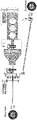
- FIG. 1 A schematic view of an all-wheel drive system 10 for a vehicle 12 according to the inventive Concept 1 is shown in Figure 1 .
- the vehicle 12 is generally indicated by its system boundaries in the present disclosure, with reference to some of the relevant components in more detail.
- the vehicle 12 has a front axle 14 and a rear axle 16.
- the front axle 14 and rear axle 16 of the vehicle normally comprise axle differentials for torque distribution between left and right wheels of the respective axle, which are however not essential to operate the invention disclosed herein.
- the front axle 14 and rear axle 16 are connected or connectable to the all-wheel drive system 10 via a front drive shaft 15 and a rear drive shaft 17, respectively. This connection may be realized via the respective differentials (if present) and may imply a gear ratio between the respective differentials and drive shafts 15, 17.
- the vehicle comprises an internal engine 18.
- the internal engine 18 may comprise an internal combustion engine 20, an internal electrical engine 22 or a combination thereof.
- the all-wheel drive system 10 of the inventive Concept 1 essentially comprises an electrical motor 24 being connected to a first axle 26 of a planetary gear set 28.
- the planetary gear set 28 is arranged at an output side 30 of a gearbox 32 of the associated vehicle 12.
- first 26, second 34, and third axle 38 of the planetary gear set 28 may be comprised by either one of a sun gear wheel 40, a planet carrier 42 or a ring gear wheel 44.
- first axle 26 is comprised by the sun gear wheel 40
- second axle 34 is comprised by the planet carrier 42
- third axle 38 is comprised by the ring gear wheel 44.
- a torque from the internal engine 18 of the vehicle 12 is delivered via the vehicle gearbox 32 and split up in a pre-defined ratio among the front 14 and rear axles 16.
- the electrical motor 24 is then capable of operating at a level appropriate to compensate for any wheel slip that may occur between the front 14 and rear axles 16 during operation of the vehicle 12 in a very fast and accurate manner. This operating level may be around zero rotations per minute and is proportional to the wheel slip to be compensated for.
- This mode is referred to as a longitudinal torque vectoring all-wheel drive (AWD) mode of Concept 1 herein.
- the rear axle 16 is driven by the internal engine 18 of the vehicle 12 and the front axle 14 is driven by the electrical motor 24.
- the electrical motor 24 is capable of adapting the front wheel drive (FWD) with respect to any wheel slip occurring between the wheels of the front 14 and rear axle 16.
- FWD front wheel drive
- ATD hybrid all-wheel drive
- the coupling I is a switchable coupling 46, preferably but optionally a non-friction clutch.
- said switchable non-friction clutch 46 is a dog clutch 48.
- said coupling I in a disconnected state, said coupling I is connecting the second axle 34 of the planetary gear set 28 to ground G.
- the all-wheel drive system 10 as in the preferred embodiment shown in Figure 1 further comprises a second switchable coupling II and a third switchable coupling III.
- the all-wheel drive system 10 shown in Figure 1 allows for configuration of a variety of different drive modes by configuring different combinations of opening or closing the couplings I, II and III.
- All realizable drive modes can be derived by a skilled person from the shown system set-up, depending on the opening or closing state of each coupling I, II, III and the operational state of the respective engines 18, 24. In the following, five of these modes are described in further detail:
- a first drive mode also referred to as an electric vehicle drive mode of Concept 1
- the coupling I is connected to ground G
- the second coupling II is open and the third coupling III is closed.
- the internal engine 18 of the vehicle 12 is not providing any torque to any of the front 14 or rear axles 16.
- the first drive mode is an electric front wheel drive mode (FWD).
- the drive voltage applied to the electrical motor 24 may be 48 V, for example, but could be any other suitable drive voltage.
- a second drive mode also referred to as a hybrid drive mode of Concept 1, which preferably is an all-wheel drive mode (AWD)
- the coupling I is connected to ground G
- the second coupling II is closed and the third coupling III is closed.
- the coupling I is connected to ground G
- the planet carrier 42 is standing still.
- the second coupling II is also closed, the internal engine 18 of the vehicle 12 is providing a torque to the rear axle 16 via the gearbox output shaft 36 and the rear drive shaft 17.
- the third coupling III is also closed, the torque from the electrical motor 24 is transmitted to the front axle 14 in the above stated manner.
- the second drive mode is an internal engine 18 rear wheel drive mode (RWD) and electric front wheel drive mode (FWD).
- RWD rear wheel drive mode
- FWD electric front wheel drive mode
- this can be a low speed all-wheel drive mode (AWD).
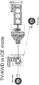
- a third drive mode also referred to as a longitudinal torque vectoring drive mode (TVD) of Concept 1, which preferably is an all-wheel drive mode (AWD)
- TVD longitudinal torque vectoring drive mode
- AWD all-wheel drive mode
- the coupling I is connected to the gearbox output shaft 36, the second coupling II is closed and the third coupling III is closed.
- the internal engine 18 of the vehicle 12 is providing a torque to the rear axle 16 via the gearbox output shaft 36 and the rear drive shaft 17 and at the same time to the planet carrier 42, which passes on the torque to the front axle 14 via the ring gear wheel 44 and the third coupling III.
- the torque controlled to be supplied by the electrical motor 24 is proportional to the desired transfer of torque between the rear axle 16 and the front axle 14.
- the torque is controlled to be at a pre-defined level, which leads to a split of the torque supplied by the internal engine 18 among the rear drive shaft 17 and the front drive shaft 15 in a pre-defined ratio, according to the desired dynamic vehicle 12 properties for different driving situations. If a wheel slip occurs, the electrical motor 24 is controlled to operate at a rotational speed and torque proportional to the wheel slip between the rear axle 16 and the front axle 14.
- a fourth drive mode also referred to as a low drag mode, sailing mode or disconnected mode of Concept 1
- the coupling I is connected to ground G and the second coupling II and third coupling III are open.
- the planetary gear set 28 is standing still and none of the front 14 or rear axles 16 are connected to any torque source of the vehicle 12.
- the vehicle 12 is rolling freely, depending on its current kinetic energy.
- a fifth drive mode also referred to as an internal engine 18 drive mode of Concept 1
- the coupling I is connected to ground G
- the second coupling II is closed and the third coupling III is open.
- the front axle 14 is disconnected from the drive system and the rear axle 16 is driven by the internal engine 18. Accordingly, this is a rear wheel drive mode (RWD).
- RWD rear wheel drive mode
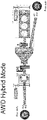
- FIG 2 shows a simplified illustration of the embodiment shown in Figure 1 , only with coupling I. However, the same embodiment is compatible with all features as described with reference to Figure 1 .
- the electrical motor 24 is connected to the planetary gear set 28 via an electrical motor gear wheel 50 comprising a number of teeth Z EM .
- the electrical motor gear wheel 50 is engaged with a second electrical motor gear wheel 52 comprising a number of teeth Z EM2 .
- the second electrical motor gear wheel 52 is connected to the sun gear wheel 40 comprising a number of teeth Za.
- the sun gear wheel 40 is engaged with the planet gear wheels 43 comprising a number of teeth Zb.
- the planet gear wheel 43 is engaged with the ring gear wheel 44 comprising a number of teeth Zc.
- the ring gear wheel 44 Directed to the front axle 14, the ring gear wheel 44 has a number of teeth Z f1 and is engaged with a gear wheel 54 having a number of teeth Z f2 and being functionally connected to the front drive shaft 15.
- gear ratios may apply:
- the above ratios are for example relevant for the longitudinal torque vectoring drive (TVD) mode, the third drive mode of Concept 1 respectively, wherein torque vectoring between the front 14 and rear axles 16 is done via the electrical motor 24.
- TVD longitudinal torque vectoring drive
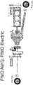
- FIG 3 there is a schematic view of an all-wheel drive system 10 for a vehicle 12 according to another embodiment of the inventive Concept 1, which is similar to the embodiments shown in Figures 1 and 2 . Therefore, only the differences will be described.
- the front drive shaft 15 is indirectly connected to the planetary gear set 28 via the gearbox 32.
- a front wheel drive (FWD) mode without the electrical motor 24 can be configured by closing coupling II, whereas the state of coupling I can be either connected to ground G or to the gearbox output shaft 36.
- a hybrid all-wheel drive mode can be configured by closing coupling II and connecting coupling I to ground G.
- an electric rear wheel drive (RWD) mode can be configured by opening coupling II and putting coupling I to ground G.
- TVD longitudinal torque vectoring
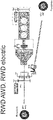
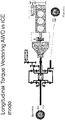
- Figures 4 and 5 are schematically showing an all-wheel drive system 10 for a vehicle 12 according to an embodiment of the inventive Concept 2 and are referred to commonly, if not stated otherwise.
- the Figures show the all-wheel drive system 10, that essentially comprises a differential 56 arranged between a vehicle gearbox 32 and a front 14 and rear axle 16 of the associated vehicle 12. Further, there is a first planetary gear set 28 having a planetary gear set output 58 being connected to one of the differential outputs 60. Further there is a second planetary gear set 62 having a planetary gear set output 64 being connected to the other one of the differential outputs 68. The first 28 and second planetary gear set 62 are sharing a common ring wheel 44, and an electrical motor 24 is selectively connectable to one of the planetary gear sets 28 or to a gearbox output shaft 36 by means of a coupling I.
- the system 10 of Figures 4 and 5 also comprises an internal engine 18.
- the planetary gear set output 58 being connected to the one of the differential outputs 60, is a planet carrier 42 in this example and the differential output 60 is a bevel gear 66 in this example.
- the planetary gear set output 64 connected to the other differential output 68, also is a planet carrier 70 in this example and the other differential output 68 is a bevel gear 72, too.
- the gearbox output shaft 36 is connected to a cage 74 of the differential 56.
- the front axle 14 is functionally connected or connectable to the planetary gear set 28, in this example via a connecting gear 78 that is exemplarily engaged with a planet gear wheel 43 of the planetary gear set 28.
- the coupling I in the inventive Concept 2 is a switchable coupling 46.
- the coupling I is a switchable non-friction clutch 46.
- the coupling 46 is embodied by a coupling sleeve 76.
- the coupling sleeve 76 is switchable between a connected state, wherein it connects the electrical motor 24 to the planetary gear set 28 and a disconnected state, wherein the coupling I is connecting the electrical motor 24 to the gearbox output shaft 36.
- non-friction clutch 46 for example the coupling sleeve 76
- said non-friction clutch 46 can be switched to a neutral state (not shown), as well, wherein said non-friction clutch 46 is disconnecting the electrical motor 24 from the planetary gear set 28 and from the gearbox output shaft 36, in order to adapt the rotational speed of the electrical motor 24 to that of the respective component, the electrical motor 24 is to be coupled to.
- this neutral state is advantageous for the above reasons.
- a first drive mode shown in Figure 4 which may be referred to as a longitudinal torque vectoring (TVD) mode of Concept 2
- the coupling I connects the electrical motor 24 to the planetary gear set 28 and coupling II is closed.
- a torque delivered by the internal engine 18 is distributed in a pre-defined ratio, for example equally, to the front 14 and rear axle 16 via the cage 74 to achieve an all-wheel drive (AWD).
- AWD all-wheel drive
- the electrical motor 24 is operated, preferably proportionally to a wheel slip between the front 14 and rear axle 16, additional torque is delivered to the front axle 14 via the planet carrier 42.
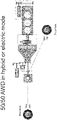
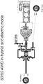
- a second drive mode shown in Figure 5 which may be referred to as an electric vehicle drive mode of Concept 2, the coupling I connects the electrical motor 24 to the gearbox output shaft 36 and coupling II is open. Thus, no torque can be delivered by the internal engine 18. If the electrical motor 24 is operated, a torque will be delivered to the front 14 and rear axle 16 via the cage 74 of the differential 56. Thus, a fully electric all-wheel drive (AWD) mode is achieved.
- ATD all-wheel drive
- a third drive mode shown in Figure 5 which may be referred to as a hybrid mode of Concept 2
- the coupling I connects the electrical motor 24 to the gearbox output shaft 36 and coupling II is closed.
- a torque can be delivered by the internal engine 18 and also by the electrical motor 24 to the gearbox output shaft 36.
- the torque will be delivered to the front 14 and rear axle 16 via the cage 74 of the differential 56.
- a hybrid all-wheel drive (AWD) can be achieved by both said engines 18, 24 or an all-wheel drive (AWD) can be achieved by either of said engines 18, 24.
- AWD Performance Reference performance e.g. 48V AWD in normal mode; longitudinal torque vectoring AWD in performance mode (improved) e.g. 50/50 AWD in normal mode; longitudinal torque vectoring AWD in performance mode (improved)
- a power split all wheel drive and P3 system The present invention relates to an improved system for all wheel drive (AWD) of a vehicle.
- the present invention seeks to overcome the drawbacks of existing systems by providing an improved system as defined by the independent numbered embodiment.
- Preferred embodiments are defined by the dependent embodiments.
- An AWD system is shown in Additional Illustration 1, in the below denoted "Concept 1".
- the system allows for four different operational modes:
Landscapes
- Engineering & Computer Science (AREA)
- Chemical & Material Sciences (AREA)
- Combustion & Propulsion (AREA)
- Transportation (AREA)
- Mechanical Engineering (AREA)
- Arrangement And Driving Of Transmission Devices (AREA)
- Hybrid Electric Vehicles (AREA)
Abstract
Description
- The present invention relates to an all-wheel drive (AWD) system for a vehicle.
- Existing solutions to provide all-wheel drive in a vehicle have been on the market for many years. In the state of the art, for example, so called P3-drive-systems are well known. This type of drive system commonly refers to a drive system for a vehicle, comprising a first motor, such as a combustion motor and a second motor, such as an electrical motor. In P3-systems, the electrical motor is connected to an output shaft of a gearbox of the associated vehicle.
- However, as the technology develops there is a need of further improvement, especially with regard to fuel consumption and driving characteristics.
- For example, the patent document
US 20190061521 A1 discloses a transfer case of an all-wheel drive system for a vehicle. The system comprises an electric motor being connected to a first axle in the form of a sun gear's axle of a planetary gear set. The planetary gear set is arranged at an output side formed by an output shaft of a transmission. Further, there is a coupling and a second axle of the planetary gear set formed by a ring gear's axle of the planetary gear set. Said ring gear's axle is permanently connected to the output shaft and the coupling is selectively locking the rotation of the ring gear to a housing of the transfer case or unlocking the rotation of the ring gear. Moreover, there is a third axle in the form of a planet gear's axle of the planetary gear set. Said third axle is connected to a rear axle of the respective vehicle. - The patent document
WO 2017178595 A2 discloses another all-wheel drive system for a vehicle that comprises a differential. There is a first planetary gear set comprising a planetary gear set output, which is connected to a housing of the differential. The housing forms a differential output. Further, there is a second planetary gear set with a planetary gear set output, which is connected to a right output shaft of the differential, forming another differential output. The first and second planetary gear sets are sharing a common ring wheel. The differential is arranged on-axis of a respective front or rear axle of said vehicle. - Finally, the patent document
US 20060079369 A1 shows a vehicle drive system, wherein a differential embodied by a planetary gear set is arranged between a transmission, a front axle and a rear axle of the vehicle. - The present invention seeks to overcome the drawbacks of existing systems by providing an improved all-wheel drive system. One of the objectives underlying the present invention in particular is to provide an all-wheel drive system that is highly efficient and features improved driving characteristics.
- These objectives are achieved by the technical subject-matter of the
independent claims 1 and 4. Preferred embodiments of the present invention can be gained from the dependent claims and the present disclosure in general. - The technical solutions of the
independent claims 1 and 4 are solving the above problems by addressing an overall technical task, with its technical solution being implemented in two alternativetechnical Concepts - The overall technical task is to provide an all-wheel drive system for a vehicle that is capable of effectively controlling a wheel slip between a front and rear axle of the associated vehicle.
- A first aspect of the invention refers to an all-wheel drive system for a vehicle, comprising:
- an electrical motor being connected to a first axle of a planetary gear set arranged at an output side of a vehicle gearbox, and
- a second axle of the planetary gear set being connected or connectable to the gearbox output shaft or to ground by a coupling,
- while a third axle of the planetary gear set is connected or connectable to the front axle of the associated vehicle.
- The inventive solution according to the first aspect of the invention is also referred to herein as "
Concept 1". - The coupling can be embodied by a permanent connection, which means a permanent non-switchable coupling, or by a switchable coupling. Based on this inventive solution of
Concept 1, a wheel slip between a front and rear axle of the associated vehicle can be controlled at a significantly decreased response time compared to a conventional all-wheel drive system using frictional clutches. This is based on the electrical motor that is permanently connected to the planetary gear set and can be controlled for the purpose of wheel slip adjustment in a very fast and accurate manner. The inventive solution of Concept 1 in particular controls the front and rear wheel slip by appropriate allocation of torque between the respective front and rear wheels, which is achieved by appropriate operation of the electrical engine. This means, controlling said wheel slip in particular refers to controlling a torque split between the front and rear axle. - The response time herein is defined as a time span from requesting a torque from the electrical motor to its impact on the front and/or rear axle.
- If the second axle of the planetary gear set is permanently connected to the gearbox output shaft via a non-switchable coupling, a torque from an internal engine of the vehicle is delivered via the vehicle gearbox and split up in a pre-defined ratio among the front and rear axles. The electrical motor is then capable of operating at a level appropriate to compensate for a wheel slip that may occur during operation of the vehicle in a very fast and accurate manner. This is referred to as a longitudinal torque vectoring all-wheel drive mode of
Concept 1 herein. Generally, when referring to a motor or engine herein, this term is not limited to either an electrical, combustion or other type of engine or motor. Both terms are used as synonyms herein, unless the present disclosure states anything more specific. - If the second axle of the planetary gear set is permanently connected to ground via a non-switchable coupling, the rear axle is driven by the internal engine of the vehicle and the front axle is driven by the electrical engine. Connected to ground generally refers to being connected to a static structure of the system. Again, the electrical motor is capable of adapting the front wheel drive with respect to any wheel slip occurring between the front and rear axle. This is referred to as a hybrid all-wheel drive mode of Concept 1 herein.
- If the second axle of the planetary gear set is selectively connectable either to the gearbox output shaft or to ground via a switchable coupling, it can be switched between the above described modes.
- Based on that, at least two drive modes can be realized with a switchable coupling. There can be more switchable couplings comprised by the all-wheel drive system of the
inventive Concept 1 in order to enable for additional drive modes that will be described in further detail later on. For example, a second coupling can be provided selectively connecting the internal engine of the vehicle to the vehicle gearbox and a third coupling can be provided selectively connecting the third axle of the planetary gear set to the front axle of the vehicle. - While allowing for a variety of different drive modes, the response time is kept at a very low level and a high torque accuracy is achieved. At the same time, the technical system complexity remains at a low level. As a secondary effect, the fuel consumption of the vehicle is also decreased. With regard to energy efficiency, in the
inventive Concept 1 the kinetic energy of the rotating drive shafts may be used to charge a battery via the permanently connected electrical motor, for example. This implies operational states, wherein the system counteracts wheel slip, which means the electrical motor may be acting as a generator. Theinventive Concept 1 in particular works without any need of friction clutches, since the rotational speed of rotating axles, that are to be coupled to each other, can be synchronized prior to coupling by appropriate control of the electrical motor in a fast and accurate manner. - In a preferred embodiment of the all-wheel drive system of the
inventive Concept 1, the coupling is switchable and in a disconnected state, the coupling is disconnected from the gearbox output shaft and connecting the second axle of the planetary gear set to ground. - This embodiment allows for fast and easy switching of drive modes by synchronization of the drive shafts by appropriate control of the electrical motor followed by connecting or disconnecting the coupling.
- In a preferred embodiment of the all-wheel drive system of the
inventive Concept 1, the first, second, and third axles of the planetary gear set are comprised by either one of a sun gear wheel, a planet carrier or a ring gear wheel. Said first, second, and third axles of the planetary gear set can be comprised by said components of the planetary gear set in any configuration, which merely as an example means said first axle can be comprised by said sun gear wheel, said second axle can be comprise by said planet carrier and said third axle can be comprised by said ring gear wheel. The first, second, and third axles of the planetary gear set can also embody either of said components of the planetary gear set. - Based on that, the system design of the
inventive Concept 1 is very flexible. - A second aspect of the present invention refers to an all-wheel drive system for a vehicle, comprising:
- a differential arranged between a vehicle gearbox and a front and rear axle of an associated vehicle,
- a first planetary gear set having a planetary gear set output being connected to one of the differential outputs, and
- a second planetary gear set having a planetary gear set output being connected to the other one of the differential outputs, wherein
said first and second planetary gear set are sharing a common ring wheel, and an electrical motor is selectively connectable to one of the planetary gear sets or to a gearbox output shaft by means of a coupling. - The alternative inventive solution according to the second aspect of the invention is also referred to herein as "
Concept 2". - The coupling in the
inventive Concept 2 is embodied by a switchable coupling. Based on this inventive solution ofConcept 2, a wheel slip, or torque split respectively, between a front and rear axle of the associated vehicle can be controlled at a significantly decreased response time compared to a conventional all-wheel drive system using frictional clutches. This is based on the electrical motor that is either connected to the respective planetary gear set or can be connected very quickly to it and allows for controlling of any torque split between the front and rear axles in a very fast and accurate manner. - If the electrical motor is connected to one of the planetary gear sets, a torque from an internal engine of the vehicle is delivered via the vehicle gearbox and distributed in a pre-defined ratio among the front and rear axles via the differential. The electrical motor is then capable of operating at a level appropriate to compensate for any wheel slip that may occur during operation of the vehicle in a very fast and accurate manner. This is referred to as a longitudinal torque vectoring all-wheel drive mode of
Concept 2 herein. - If the electrical motor is connected to the gearbox output shaft, the combined torque delivered by the internal engine and the electrical motor is distributed in a pre-defined ratio among the front and rear axles via the differential. This is referred to as a hybrid all-wheel drive mode of
Concept 2 herein. - Based on that, two drive modes can be realized with the switchable coupling. There can be more switchable couplings comprised by the all-wheel drive system of the
inventive Concept 2 in order to enable for additional drive modes that will be described in further detail later on. For example, a second coupling can be provided selectively connecting the internal engine of the vehicle to the vehicle gearbox and a third coupling can be provided selectively connecting the front or rear axle to one of the planetary gear sets. - While allowing for a variety of different drive modes, the response time is kept at a very low level and a high torque accuracy is achieved. At the same time, the technical system complexity remains at a low level. As a secondary effect, the fuel consumption of the vehicle is also decreased. With regard to energy efficiency, in the
inventive Concept 2 the kinetic energy of the rotating drive shafts may be used to charge a battery via the electrical motor if it is connected, for example. Theinventive Concept 2 in particular works without any need of friction clutches, since the rotational speed of rotating axles, that are to be coupled to each other, can be synchronized prior to coupling by appropriate control of the electrical motor in a fast and accurate manner. - In a preferred embodiment of the all-wheel drive system of the
inventive Concept 2, in a disconnected state, the coupling is connecting the electrical motor to the gearbox output shaft. - In a preferred embodiment of the all-wheel drive system of any of the
inventive Concepts - The possibility of using a non-friction clutch is particularly related to the use of the electrical motor that allows for fast and safe synchronization of the respective rotating axles that are to be coupled.
- This also decreases the system costs and the packaging size and improves the thermal behaviour of the system, due to decreased friction effects. The overall efficiency of the system is therefore further improved.
- In a further preferred embodiment of the all-wheel drive system of any of the
inventive Concepts - These types of non-friction clutches are robust, of low complexity, durable and can be actuated at a high speed. Further, these types of clutches realize an immediate torsionally rigid connection.
- A third aspect of the invention refers to a vehicle, comprising an all-wheel drive system according to any embodiment of the
inventive Concepts - In the following, reference will be made to the appended Figures, in which:
-
Fig. 1 is a schematic view of an all-wheel drive system for a vehicle according to an embodiment of theinventive Concept 1; -
Fig. 2 is a schematic view of an all-wheel drive system for a vehicle according to another embodiment of theinventive Concept 1 related toFig. 1 ; -
Fig. 3 is a schematic view of an all-wheel drive system for a vehicle according to another embodiment of theinventive Concept 1 related toFig. 1 and2 ; and -
Figs. 4 and5 are schematic views of an all-wheel drive system according to an embodiment of theinventive Concept 2. - Further, reference will be made to the appended Additional Illustrations, in which Additional Illustrations 1-18 are showing further technical subject-matter that forms part of the present disclosure.
- A schematic view of an all-
wheel drive system 10 for avehicle 12 according to theinventive Concept 1 is shown inFigure 1 . Thevehicle 12 is generally indicated by its system boundaries in the present disclosure, with reference to some of the relevant components in more detail. Thevehicle 12 has afront axle 14 and arear axle 16. Thefront axle 14 andrear axle 16 of the vehicle normally comprise axle differentials for torque distribution between left and right wheels of the respective axle, which are however not essential to operate the invention disclosed herein. Thefront axle 14 andrear axle 16 are connected or connectable to the all-wheel drive system 10 via afront drive shaft 15 and arear drive shaft 17, respectively. This connection may be realized via the respective differentials (if present) and may imply a gear ratio between the respective differentials and driveshafts - Further, the vehicle comprises an
internal engine 18. Theinternal engine 18 may comprise aninternal combustion engine 20, an internalelectrical engine 22 or a combination thereof. - The all-
wheel drive system 10 of theinventive Concept 1 essentially comprises anelectrical motor 24 being connected to afirst axle 26 of a planetary gear set 28. The planetary gear set 28 is arranged at anoutput side 30 of agearbox 32 of the associatedvehicle 12. There is a coupling I permanently or selectively connecting asecond axle 34 of the planetary gear set 28 to agearbox output shaft 36 or to ground G, while athird axle 38 of the planetary gear set 28 is connected or connectable to thefront axle 14 of the associatedvehicle 12. - Optionally, the first 26, second 34, and
third axle 38 of the planetary gear set 28 may be comprised by either one of asun gear wheel 40, aplanet carrier 42 or aring gear wheel 44. In the embodiment shown inFigure 1 , merely as one of these options, thefirst axle 26 is comprised by thesun gear wheel 40, thesecond axle 34 is comprised by theplanet carrier 42 and thethird axle 38 is comprised by thering gear wheel 44. - If the
second axle 34 of the planetary gear set 28 is permanently connected to thegearbox output shaft 36 via a non-switchable coupling I, a torque from theinternal engine 18 of thevehicle 12 is delivered via thevehicle gearbox 32 and split up in a pre-defined ratio among the front 14 andrear axles 16. Theelectrical motor 24 is then capable of operating at a level appropriate to compensate for any wheel slip that may occur between the front 14 andrear axles 16 during operation of thevehicle 12 in a very fast and accurate manner. This operating level may be around zero rotations per minute and is proportional to the wheel slip to be compensated for. This mode is referred to as a longitudinal torque vectoring all-wheel drive (AWD) mode ofConcept 1 herein. - If the
second axle 34 of the planetary gear set 28 is permanently connected to ground G via a non-switchable coupling I, therear axle 16 is driven by theinternal engine 18 of thevehicle 12 and thefront axle 14 is driven by theelectrical motor 24. Again, theelectrical motor 24 is capable of adapting the front wheel drive (FWD) with respect to any wheel slip occurring between the wheels of the front 14 andrear axle 16. This mode is referred to as a hybrid all-wheel drive (AWD) mode ofConcept 1 herein. - In the preferred embodiment shown in
Figure 1 , the coupling I is aswitchable coupling 46, preferably but optionally a non-friction clutch. In particular preferred but optional, said switchable non-friction clutch 46 is adog clutch 48. In the illustrated embodiment, in a disconnected state, said coupling I is connecting thesecond axle 34 of the planetary gear set 28 to ground G. - The all-
wheel drive system 10 as in the preferred embodiment shown inFigure 1 further comprises a second switchable coupling II and a third switchable coupling III. - Based on that, the all-
wheel drive system 10 shown inFigure 1 allows for configuration of a variety of different drive modes by configuring different combinations of opening or closing the couplings I, II and III. All realizable drive modes can be derived by a skilled person from the shown system set-up, depending on the opening or closing state of each coupling I, II, III and the operational state of therespective engines
In a first drive mode, also referred to as an electric vehicle drive mode ofConcept 1, the coupling I is connected to ground G, the second coupling II is open and the third coupling III is closed. As the second coupling II is open, theinternal engine 18 of thevehicle 12 is not providing any torque to any of the front 14 orrear axles 16. As the coupling I is connected to ground G, thesecond axle 34, which is theplanet carrier 42 in this example, of the planetary gear set 28 stands still. Thus, a torque delivered by theelectrical motor 24 is transmitted via thefirst axle 26, which is thesun gear wheel 40 in this example, via aplanet gear wheel 43 of the planetary gear set 28 to thethird axle 38, which is thering gear wheel 44 in this example. The torque is then further transmitted via thefront drive shaft 15 and the closed third coupling III to thefront axle 14. Thus, the first drive mode is an electric front wheel drive mode (FWD). The drive voltage applied to theelectrical motor 24 may be 48 V, for example, but could be any other suitable drive voltage. - In a second drive mode, also referred to as a hybrid drive mode of
Concept 1, which preferably is an all-wheel drive mode (AWD), the coupling I is connected to ground G, the second coupling II is closed and the third coupling III is closed. As the coupling I is connected to ground G, theplanet carrier 42 is standing still. As the second coupling II is also closed, theinternal engine 18 of thevehicle 12 is providing a torque to therear axle 16 via thegearbox output shaft 36 and therear drive shaft 17. At the same time, as the third coupling III is also closed, the torque from theelectrical motor 24 is transmitted to thefront axle 14 in the above stated manner. Thus, the second drive mode is aninternal engine 18 rear wheel drive mode (RWD) and electric front wheel drive mode (FWD). For example, this can be a low speed all-wheel drive mode (AWD). - In a third drive mode, also referred to as a longitudinal torque vectoring drive mode (TVD) of
Concept 1, which preferably is an all-wheel drive mode (AWD), the coupling I is connected to thegearbox output shaft 36, the second coupling II is closed and the third coupling III is closed. As the second coupling II is closed, theinternal engine 18 of thevehicle 12 is providing a torque to therear axle 16 via thegearbox output shaft 36 and therear drive shaft 17 and at the same time to theplanet carrier 42, which passes on the torque to thefront axle 14 via thering gear wheel 44 and the third coupling III. The torque controlled to be supplied by theelectrical motor 24 is proportional to the desired transfer of torque between therear axle 16 and thefront axle 14. As long as no wheel slip occurs, the torque is controlled to be at a pre-defined level, which leads to a split of the torque supplied by theinternal engine 18 among therear drive shaft 17 and thefront drive shaft 15 in a pre-defined ratio, according to the desireddynamic vehicle 12 properties for different driving situations. If a wheel slip occurs, theelectrical motor 24 is controlled to operate at a rotational speed and torque proportional to the wheel slip between therear axle 16 and thefront axle 14. - In a fourth drive mode, also referred to as a low drag mode, sailing mode or disconnected mode of
Concept 1, the coupling I is connected to ground G and the second coupling II and third coupling III are open. This means, the planetary gear set 28 is standing still and none of the front 14 orrear axles 16 are connected to any torque source of thevehicle 12. Thus, thevehicle 12 is rolling freely, depending on its current kinetic energy. - In a fifth drive mode, also referred to as an
internal engine 18 drive mode ofConcept 1, the coupling I is connected to ground G, the second coupling II is closed and the third coupling III is open. In this mode, thefront axle 14 is disconnected from the drive system and therear axle 16 is driven by theinternal engine 18. Accordingly, this is a rear wheel drive mode (RWD). -
Figure 2 shows a simplified illustration of the embodiment shown inFigure 1 , only with coupling I. However, the same embodiment is compatible with all features as described with reference toFigure 1 . Theelectrical motor 24 is connected to the planetary gear set 28 via an electricalmotor gear wheel 50 comprising a number of teeth ZEM. The electricalmotor gear wheel 50 is engaged with a second electricalmotor gear wheel 52 comprising a number of teeth ZEM2. The second electricalmotor gear wheel 52 is connected to thesun gear wheel 40 comprising a number of teeth Za. Thesun gear wheel 40 is engaged with theplanet gear wheels 43 comprising a number of teeth Zb. Theplanet gear wheel 43 is engaged with thering gear wheel 44 comprising a number of teeth Zc. Directed to thefront axle 14, thering gear wheel 44 has a number of teeth Zf1 and is engaged with a gear wheel 54 having a number of teeth Zf2 and being functionally connected to thefront drive shaft 15. - Preferably, the number of teeth may have the following configurations:


- Based on that, the following gear ratios may apply:
-
electrical motor 24 torear drive shaft 17 = ZEM2 / - ZEM∗(Zc/Za+1)=94/25∗(129/43+1)=+15;
-
electrical motor 24 tofront drive shaft 15 = ZEM2 / - ZEM ∗(Zc/Za)∗(Zf2/Zf1)=94/25∗(-129/43)∗(-57/43)=15; and
- internal engine 18 (not shown) to
rear drive shaft 17 = 1. - The above ratios are for example relevant for the longitudinal torque vectoring drive (TVD) mode, the third drive mode of
Concept 1 respectively, wherein torque vectoring between the front 14 andrear axles 16 is done via theelectrical motor 24. - Further, the following gear ratios may apply:


- The above ratios are for example relevant for the hybrid drive mode of
Concept 1, the second drive mode respectively, wherein coupling I is connected to ground G. - Also the following gear ratios may apply, for example to the longitudinal torque vectoring drive (TVD) mode of Concept 1:
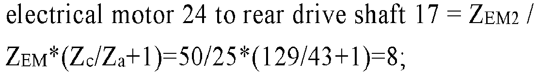

- Also the following gear ratios may apply, for example to the hybrid drive mode of Concept 1:


- In
Figure 3 , there is a schematic view of an all-wheel drive system 10 for avehicle 12 according to another embodiment of theinventive Concept 1, which is similar to the embodiments shown inFigures 1 and2 . Therefore, only the differences will be described. - As can be seen in
Figure 3 , thefront drive shaft 15 is indirectly connected to the planetary gear set 28 via thegearbox 32. Based on that, a front wheel drive (FWD) mode without theelectrical motor 24 can be configured by closing coupling II, whereas the state of coupling I can be either connected to ground G or to thegearbox output shaft 36. Further, a hybrid all-wheel drive mode can be configured by closing coupling II and connecting coupling I to ground G. Further, an electric rear wheel drive (RWD) mode can be configured by opening coupling II and putting coupling I to ground G. To achieve a longitudinal torque vectoring (TVD) mode, coupling II needs to be closed and coupling I needs to be connected to thegearbox output shaft 36. -
Figures 4 and5 are schematically showing an all-wheel drive system 10 for avehicle 12 according to an embodiment of theinventive Concept 2 and are referred to commonly, if not stated otherwise. - The Figures show the all-
wheel drive system 10, that essentially comprises a differential 56 arranged between avehicle gearbox 32 and a front 14 andrear axle 16 of the associatedvehicle 12. Further, there is a first planetary gear set 28 having a planetary gear setoutput 58 being connected to one of the differential outputs 60. Further there is a second planetary gear set 62 having a planetary gear setoutput 64 being connected to the other one of the differential outputs 68. The first 28 and second planetary gear set 62 are sharing acommon ring wheel 44, and anelectrical motor 24 is selectively connectable to one of the planetary gear sets 28 or to agearbox output shaft 36 by means of a coupling I. - The focus of the description of
Concept 2 will be put on the differences toConcept 1 and in particular to the part of thesystem 10 starting from thegearbox output shaft 36 in the direction of itsfront 14 andrear axles 16. Apart from that, if not different statement is made herein, reference can be fully made to the foregoing description. - The
system 10 ofFigures 4 and5 also comprises aninternal engine 18. Just as an example, the planetary gear setoutput 58, being connected to the one of thedifferential outputs 60, is aplanet carrier 42 in this example and thedifferential output 60 is abevel gear 66 in this example. Further, merely as an example, the planetary gear setoutput 64, connected to the otherdifferential output 68, also is aplanet carrier 70 in this example and the otherdifferential output 68 is abevel gear 72, too. Exemplarily, thegearbox output shaft 36 is connected to acage 74 of the differential 56. - Illustrated couplings II and III in this
Concept 2 are optional if not stated otherwise, but are preferred and therefore illustrated inFigures 4 and5 . Thefront axle 14 is functionally connected or connectable to the planetary gear set 28, in this example via a connectinggear 78 that is exemplarily engaged with aplanet gear wheel 43 of the planetary gear set 28. - The coupling I in the
inventive Concept 2 is aswitchable coupling 46. Preferably, the coupling I is a switchable non-friction clutch 46. Particularly preferred and illustrated inFigures 4 and5 thecoupling 46 is embodied by acoupling sleeve 76. - As can be seen in
Figures 4 and5 , thecoupling sleeve 76 is switchable between a connected state, wherein it connects theelectrical motor 24 to the planetary gear set 28 and a disconnected state, wherein the coupling I is connecting theelectrical motor 24 to thegearbox output shaft 36. It will be understood by a person skilled in the art, that in case of the non-friction clutch 46, for example thecoupling sleeve 76, said non-friction clutch 46 can be switched to a neutral state (not shown), as well, wherein said non-friction clutch 46 is disconnecting theelectrical motor 24 from the planetary gear set 28 and from thegearbox output shaft 36, in order to adapt the rotational speed of theelectrical motor 24 to that of the respective component, theelectrical motor 24 is to be coupled to. Also in case of a friction clutch, this neutral state is advantageous for the above reasons. - Based on this, for example three drive modes can be configured:
In a first drive mode shown inFigure 4 , which may be referred to as a longitudinal torque vectoring (TVD) mode ofConcept 2, the coupling I connects theelectrical motor 24 to the planetary gear set 28 and coupling II is closed. Thus, a torque delivered by theinternal engine 18 is distributed in a pre-defined ratio, for example equally, to the front 14 andrear axle 16 via thecage 74 to achieve an all-wheel drive (AWD). If theelectrical motor 24 is operated, preferably proportionally to a wheel slip between the front 14 andrear axle 16, additional torque is delivered to thefront axle 14 via theplanet carrier 42. - In a second drive mode shown in
Figure 5 , which may be referred to as an electric vehicle drive mode ofConcept 2, the coupling I connects theelectrical motor 24 to thegearbox output shaft 36 and coupling II is open. Thus, no torque can be delivered by theinternal engine 18. If theelectrical motor 24 is operated, a torque will be delivered to the front 14 andrear axle 16 via thecage 74 of the differential 56. Thus, a fully electric all-wheel drive (AWD) mode is achieved. - In a third drive mode shown in
Figure 5 , which may be referred to as a hybrid mode ofConcept 2, the coupling I connects theelectrical motor 24 to thegearbox output shaft 36 and coupling II is closed. Thus, a torque can be delivered by theinternal engine 18 and also by theelectrical motor 24 to thegearbox output shaft 36. The torque will be delivered to the front 14 andrear axle 16 via thecage 74 of the differential 56. Depending on the operational state of theinternal engine 18 and theelectrical motor 24, a hybrid all-wheel drive (AWD) can be achieved by both saidengines engines - The following table provides an overview of the complexity of
Concept 1 andConcept 2 with regard to a friction-clutch based AWD in P3 configuration as known from the prior art.Feature comprised State of the art Concept 1 Concept 2Dog clutch NO (low complexity) YES (medium complexity) YES (medium complexity) Conventional (friction) clutch incl. additional actuator YES (high complexity) NO (low complexity) NO (low complexity) Transmission 2-stage gearbox or 3- stage gear box 1+1-stage gearbox + planetary gear set 2+1-stage gearboxes + 2x planetary gear set + differential - From the table it can be gained that the
inventive Concepts Concepts - The following table provides an overview of pros and cons of
Concept 1 andConcept 2 with regard to a friction-clutch based AWD in P3 configuration as known from the prior art.Feature comprised State of the art Concept 1 Concept 2Response time 100-200ms 30-50ms (improved) 30-50ms (improved) AWD Torque tolerance 10-15% 3-5 % (improved) 3-5% (improved) AWD energy consumption Slip energy converted to heat by friction clutch Slip energy convertible to electric energy in one of the slip directions. Battery drainage in opposite direction possible (improved) Slip energy convertible to electric energy in one of the slip directions. Battery drainage in opposite direction possible (improved) Complexity Reference complexity maintained maintained stick-slip-effects high low (improved) low (improved) AWD Performance Reference performance e.g. 48V AWD in normal mode; longitudinal torque vectoring AWD in performance mode (improved) e.g. 50/50 AWD in normal mode; longitudinal torque vectoring AWD in performance mode (improved) - Below, further subject-matter is disclosed that features a relation to the invention disclosed herein.
A power split all wheel drive and P3 system:
The present invention relates to an improved system for all wheel drive (AWD) of a vehicle. - Existing solutions to provide all wheel drive have been on the market for many years. However, as the technology develops there is a need to further improvements, especially with regards to fuel consumption and driving characteristics.
- The present invention seeks to overcome the drawbacks of existing systems by providing an improved system as defined by the independent numbered embodiment. Preferred embodiments are defined by the dependent embodiments.
- In the following, reference will be given by the appended Additional Illustrations in which:
- Additional Illustrations 1-2 are schematic views of an all wheel drive system according to an embodiment;
-
Additional Illustration 3 is a schematic view of an all wheel drive system according to an embodiment; and - Additional Illustrations 4-18 are schematic views of all wheel drive system according to further embodiments.
- An AWD system is shown in
Additional Illustration 1, in the below denoted "Concept 1". The system allows for four different operational modes: - Electric vehicle mode (48V FWD)
- Low speed AWD (ICE RWD and 48V FWD)
- Longitudinal Torque Vectoring AWD (Power split AWD)
- Low drag mode (planetary gear set standing still)
- In
Additional Illustration 2, some further detail of the embodiment shown inAdditional Illustration 1 are given. The following applies for torque vectoring (TV) mode and hybrid mode, respectfully. -
-

-

-
-

-

- In
Additional Illustration 3 another embodiment is shown, in the below denoted "Concept 2". The possible modes available by this embodiment are: - Electric vehicle mode (
48V 50/50 AWD) - Low speed AWD (ICE and
EM 50/50 AWD) - Longitudinal Torque Vectoring AWD (Power split AWD)
- Additional Illustrations 4-18 show other embodiments of an all wheel drive system.
Numbered embodiments: - 1. An all wheel drive system comprising a differential arranged between a vehicle gearbox and a front and rear axle of an associated vehicle, a first planetary gear set having a planetary gear set output being connected to one of the differential outputs, and a second planetary gear set having a planetary gear set output being connected to the other one of the differential outputs, said first and second planetary gear set sharing a common ring wheel, and an electrical motor being connected to one of the planetary gear sets by means of a coupling.
- 2. The all wheel drive system according to
embodiment 1, wherein in a disconnected state, the coupling is connecting the electrical motor to the gearbox output shaft. - 3. An all wheel drive system comprising an electrical motor being connected to a first axle of a planetary gear set arranged at an output side of a vehicle gearbox, and a coupling connecting a second axle of the planetary gear set to the gearbox output shaft while a third axle of the planetary gear set is connected to the front axle of the associated vehicle.
- 4. The all wheel drive system according to
embodiment 3, wherein in a disconnected state, the coupling is connecting the second axle of the planetary gear set to ground. - 5. The all wheel drive system according to any one of embodiments 1-4, wherein said coupling being a non-friction clutch.
- 6. The all wheel drive system according to embodiment 5, wherein the non-friction clutch is a dog clutch or a coupling sleeve.
- 7. The all wheel drive system according to
embodiment 3, wherein the first, second, and third axles of the planetary gear set is either one of a sun gear, a planet carrier, and a ring wheel, in any configuration.
| | | | Electric Motor | RearAxle | FrontAxle | Mode | |
| To GND | Open | Closed | Vehicle speed dependent motor RPM | Disconnected | 48V FWD | FWD EV-mode | |
| To GND | Closed | Closed | Vehicle speed dependent motor | ICE RWD | 48V FWD | Hybrid mode (Low speed AWD) | |
| To Gbox | Closed | Closed | Motor RPM working around 0 RPM RPM proportional to front to rear slip | PowerSplit AWD | PowerSplit AWD | Longitudinal Torque Vectoring AWD | |
| To GND | Open | Open | 0 RPM | Sailing | Sailing | Low drag disconnect (planetary gear set standing still) |
| | | | Electric Motor | RearAxle | FrontAxle | Mode | |
| To GBOX | Open | N/A | Vehicle speed | 48V RWD | 48V FWD | EV-mode - 50/50AWD | |
| To GBOX | Closed | N/A | Vehicle speed dependent motor RPM | ICE/EM RWD | ICE/EM FWD | Hybrid mode - 50/50 AWD | |
| To Planetary GBOX | Closed | N/A | Motor RPM working around 0 RPM RPM proportional to front to rear slip | PowerSplit ICE AWD | PowerSplit ICE AWD | Longitudinal Torque Vectoring AWD | |
| N/A | N/A | N/A | N/A | N/A | N/A | N/A |
| Friction plate AWD + | Concept | 1 | | |
| Dog clutch | YES (red color code) | YES (red color code) | YES (red color code) | |
| Conventional clutch incl. additional actuator | YES (red color code) | NO (green color code) | NO (green color code) | |
| Transmission | 2-stage gearbox (green color code) | 1+1-stage gearbox + planetary gearset (orange color code) | 2+1-stage gearboxes + 2x planetary gearsets + differential (red color code) |
| Conventional AWD Clutch with | Concept | 1 | | |
| Response time | 100-200ms (red color code) | 30-50ms (green color code) | 30-50ms (green color code) | |
| AWD Torque accuracy | 0 (red color code) | + (green color code) | + (green color code) | |
| AWD energy consumption | Slip energy converted to heat (red color code) | Slip energy converted to electric energy (battery charge) (green color code) | Slip energy converted to electric energy in one of the slip directions. Battery drainage in opposite direction (orange color code) | |
| Complexity | 0 (green color code) | 0 or - ? (green color code) | -- (red color code) | |
| Torque Capacity | Independent of front to rear slip (discarding heat development) | High front to rear slip will cause loss of torque capacity. Control must inhibit too high slip (orange color code) | High front to rear slip will cause loss of torque capacity. Control must inhibit too high slip (orange color code) | |
| NVH | 0 (red color code) | +? (green color code) | +? (green color code) | |
| AWD Performance | Conventional AWD only (red color code) | - 48V AWD in normal mode | - 50/50 AWD in normal mode | |
| - longitudinal torque vectoring AWD in performance mode (orange color code) | - longitudinal torque vectoring AWD in performance mode (green color code) |
Claims (8)
- All-wheel drive system (10) for a vehicle (12), comprising:- an electrical motor (24) being connected to a first axle (26) of a planetary gear set (28) arranged at an output side (30) of a vehicle gearbox (32), and- a second axle (34) of the planetary gear set (28) being connected or connectable to the gearbox output shaft (36) or to ground (G) by a coupling (I),- while a third axle (38) of the planetary gear set (28) is connected or connectable to the front axle (14) of the associated vehicle (12).
- All-wheel drive system (10) according to claim 1, wherein the coupling (I) is switchable and in a disconnected state, the coupling (I) is disconnected from the gearbox output shaft (36) and connecting the second axle (34) of the planetary gear set (28) to ground (G).
- All-wheel drive system (10) according to claim 1 or 2, wherein the first (26), second (34), and third axles (34) of the planetary gear set (28) are comprised by either one of a sun gear wheel (40), a planet carrier (42), and a ring gear wheel (44).
- All-wheel drive system (10) for a vehicle (12), comprising:- a differential (56) arranged between a vehicle gearbox (32) and a front (14) and rear axle (16) of an associated vehicle (12),- a first planetary gear set (28) having a planetary gear set output (58) being connected to one of the differential outputs (60), and- a second planetary gear set (62) having a planetary gear set output (64) being connected to the other one of the differential outputs (68), wherein
said first (28) and second planetary gear set (62) are sharing a common ring wheel (44), and an electrical motor (24) is electively connectable to one of the planetary gear sets (28) or to a gearbox output shaft (36) by means of a coupling (I). - All-wheel drive system (10) according to claim 4, wherein in a disconnected state, the coupling (I) is connecting the electrical motor (24) to the gearbox output shaft (36).
- All-wheel drive system (10) according to any one of the preceding claims, wherein said coupling (I) is a non-friction clutch.
- All-wheel drive system (10) according to claim 6, wherein the non-friction clutch is a dog clutch (48) or a coupling sleeve (76).
- Vehicle (12), comprising an all-wheel drive system (10) according to any of the preceding claims.
Applications Claiming Priority (1)
| Application Number | Priority Date | Filing Date | Title |
|---|---|---|---|
| SE2051341 | 2020-11-17 |
Publications (2)
| Publication Number | Publication Date |
|---|---|
| EP4035920A2 true EP4035920A2 (en) | 2022-08-03 |
| EP4035920A3 EP4035920A3 (en) | 2022-11-16 |
Family
ID=77910723
Family Applications (1)
| Application Number | Title | Priority Date | Filing Date |
|---|---|---|---|
| EP21198576.7A Pending EP4035920A3 (en) | 2020-11-17 | 2021-09-23 | Power split all-wheel drive system |
Country Status (2)
| Country | Link |
|---|---|
| US (1) | US11554656B2 (en) |
| EP (1) | EP4035920A3 (en) |
Families Citing this family (1)
| Publication number | Priority date | Publication date | Assignee | Title |
|---|---|---|---|---|
| WO2024180356A1 (en) * | 2023-02-28 | 2024-09-06 | Debreceni Egyetem | Hybrid drive for additional hybridization of commercial vehicles with conventional drives |
Citations (3)
| Publication number | Priority date | Publication date | Assignee | Title |
|---|---|---|---|---|
| US20060079369A1 (en) | 2004-05-24 | 2006-04-13 | Mohan Sankar K | Torque vectoring axle assembly |
| WO2017178595A2 (en) | 2016-04-15 | 2017-10-19 | Borgwarner Sweden Ab | A vehicle driveline system |
| US20190061521A1 (en) | 2017-08-22 | 2019-02-28 | Borgwarner Inc. | Electrified (4WD) Four Wheel Drive Device |
Family Cites Families (5)
| Publication number | Priority date | Publication date | Assignee | Title |
|---|---|---|---|---|
| US6464608B2 (en) * | 2001-02-08 | 2002-10-15 | New Venture Gear Inc. | Transfer case for hybrid vehicle |
| US6533692B1 (en) * | 2001-10-19 | 2003-03-18 | New Venture Gear, Inc. | Drivetrain with hybrid transfer case |
| DE102012021513B4 (en) * | 2012-11-02 | 2022-12-15 | Audi Ag | Transmission device of a motor vehicle |
| JP2017521293A (en) | 2014-05-06 | 2017-08-03 | ボルグワーナー スウェーデン エービー | Torque vectoring device |
| DE102017218858B4 (en) * | 2017-04-06 | 2019-02-21 | Magna powertrain gmbh & co kg | Vehicle with transfer case and method of operating this vehicle |
-
2021
- 2021-09-23 US US17/482,768 patent/US11554656B2/en active Active
- 2021-09-23 EP EP21198576.7A patent/EP4035920A3/en active Pending
Patent Citations (3)
| Publication number | Priority date | Publication date | Assignee | Title |
|---|---|---|---|---|
| US20060079369A1 (en) | 2004-05-24 | 2006-04-13 | Mohan Sankar K | Torque vectoring axle assembly |
| WO2017178595A2 (en) | 2016-04-15 | 2017-10-19 | Borgwarner Sweden Ab | A vehicle driveline system |
| US20190061521A1 (en) | 2017-08-22 | 2019-02-28 | Borgwarner Inc. | Electrified (4WD) Four Wheel Drive Device |
Also Published As
| Publication number | Publication date |
|---|---|
| US11554656B2 (en) | 2023-01-17 |
| US20220153117A1 (en) | 2022-05-19 |
| EP4035920A3 (en) | 2022-11-16 |
Similar Documents
| Publication | Publication Date | Title |
|---|---|---|
| US10094457B2 (en) | Electric all-wheel drive two speed with split double reduction planetary | |
| US10668797B2 (en) | Power transmission apparatus for a vehicle | |
| US9205739B2 (en) | Two-speed power take-off unit | |
| US9895970B2 (en) | Multi-mode drive system for transaxle applications | |
| US20160138695A1 (en) | Disconnecting awd driveline with torque-vectoring capabilities | |
| US7678003B2 (en) | Hybrid vehicle transmission with a mechanical reverse function | |
| EP1072457B1 (en) | Split helical planetary gear assembly | |
| US10940750B2 (en) | Hybrid all-wheel drive system having dynamic clutches | |
| CN105946544B (en) | Axle assembly for hybrid electric vehicle | |
| US10415679B2 (en) | Electric all-wheel drive two speed with split double reduction planetary | |
| US10605345B2 (en) | Device for torque vectoring | |
| US11951821B2 (en) | Gearbox for an electric powertrain | |
| US11739818B2 (en) | Powertrain for electric vehicle | |
| CN106461054A (en) | Gearbox unit for a motor vehicle | |
| EP4035920A2 (en) | Power split all-wheel drive system | |
| US10744876B2 (en) | System for torque vectoring | |
| EP3750728A1 (en) | Vehicle powertrain system and method for operating a vehicle powertrain system | |
| US10670128B2 (en) | All-wheel drive driveline with front limited slip differential | |
| CN116353335A (en) | Hybrid power transmission mechanism for vehicle | |
| US10150368B2 (en) | Transaxle and power take-off unit | |
| US20080090692A1 (en) | Transfer case center differential | |
| US11927253B2 (en) | Powertrain for electric vehicle |
Legal Events
| Date | Code | Title | Description |
|---|---|---|---|
| PUAI | Public reference made under article 153(3) epc to a published international application that has entered the european phase |
Free format text: ORIGINAL CODE: 0009012 |
|
| STAA | Information on the status of an ep patent application or granted ep patent |
Free format text: STATUS: THE APPLICATION HAS BEEN PUBLISHED |
|
| AK | Designated contracting states |
Kind code of ref document: A2 Designated state(s): AL AT BE BG CH CY CZ DE DK EE ES FI FR GB GR HR HU IE IS IT LI LT LU LV MC MK MT NL NO PL PT RO RS SE SI SK SM TR |
|
| PUAL | Search report despatched |
Free format text: ORIGINAL CODE: 0009013 |
|
| AK | Designated contracting states |
Kind code of ref document: A3 Designated state(s): AL AT BE BG CH CY CZ DE DK EE ES FI FR GB GR HR HU IE IS IT LI LT LU LV MC MK MT NL NO PL PT RO RS SE SI SK SM TR |
|
| RIC1 | Information provided on ipc code assigned before grant |
Ipc: B60K 17/356 20060101ALI20221007BHEP Ipc: B60K 17/35 20060101ALI20221007BHEP Ipc: B60K 17/346 20060101ALI20221007BHEP Ipc: B60K 17/344 20060101AFI20221007BHEP |
|
| STAA | Information on the status of an ep patent application or granted ep patent |
Free format text: STATUS: REQUEST FOR EXAMINATION WAS MADE |
|
| 17P | Request for examination filed |
Effective date: 20230516 |
|
| RBV | Designated contracting states (corrected) |
Designated state(s): AL AT BE BG CH CY CZ DE DK EE ES FI FR GB GR HR HU IE IS IT LI LT LU LV MC MK MT NL NO PL PT RO RS SE SI SK SM TR |