EP4035835B1 - Anchoring device for spring-damper assemblies for machines for mounting/removing vehicle suspensions - Google Patents
Anchoring device for spring-damper assemblies for machines for mounting/removing vehicle suspensions Download PDFInfo
- Publication number
- EP4035835B1 EP4035835B1 EP21217034.4A EP21217034A EP4035835B1 EP 4035835 B1 EP4035835 B1 EP 4035835B1 EP 21217034 A EP21217034 A EP 21217034A EP 4035835 B1 EP4035835 B1 EP 4035835B1
- Authority
- EP
- European Patent Office
- Prior art keywords
- spring
- assembly
- flange
- arms
- coupling
- Prior art date
- Legal status (The legal status is an assumption and is not a legal conclusion. Google has not performed a legal analysis and makes no representation as to the accuracy of the status listed.)
- Active
Links
Images


Classifications
-
- B—PERFORMING OPERATIONS; TRANSPORTING
- B25—HAND TOOLS; PORTABLE POWER-DRIVEN TOOLS; MANIPULATORS
- B25B—TOOLS OR BENCH DEVICES NOT OTHERWISE PROVIDED FOR, FOR FASTENING, CONNECTING, DISENGAGING, OR HOLDING
- B25B27/00—Hand tools, specially adapted for fitting together or separating parts or objects whether or not involving some deformation, not otherwise provided for
- B25B27/14—Hand tools, specially adapted for fitting together or separating parts or objects whether or not involving some deformation, not otherwise provided for for assembling objects other than by press fit or detaching same
- B25B27/30—Hand tools, specially adapted for fitting together or separating parts or objects whether or not involving some deformation, not otherwise provided for for assembling objects other than by press fit or detaching same positioning or withdrawing springs, e.g. coil or leaf springs
- B25B27/302—Hand tools, specially adapted for fitting together or separating parts or objects whether or not involving some deformation, not otherwise provided for for assembling objects other than by press fit or detaching same positioning or withdrawing springs, e.g. coil or leaf springs coil springs other than torsion coil springs
- B25B27/304—Hand tools, specially adapted for fitting together or separating parts or objects whether or not involving some deformation, not otherwise provided for for assembling objects other than by press fit or detaching same positioning or withdrawing springs, e.g. coil or leaf springs coil springs other than torsion coil springs by compressing coil springs
-
- B—PERFORMING OPERATIONS; TRANSPORTING
- B60—VEHICLES IN GENERAL
- B60G—VEHICLE SUSPENSION ARRANGEMENTS
- B60G2206/00—Indexing codes related to the manufacturing of suspensions: constructional features, the materials used, procedures or tools
- B60G2206/01—Constructional features of suspension elements, e.g. arms, dampers, springs
- B60G2206/90—Maintenance
- B60G2206/92—Tools or equipment used for assembling
- B60G2206/921—Coil spring compressor
Definitions
- the present invention relates to an anchoring device for spring-damper assemblies for machines for mounting/removing vehicle suspensions.
- An anchoring device according to the preamble of claim 1 is know from US6470554B1 .
- the spring generally rests in a lower region on an annular plate which is integral with the shock absorber jacket and is provided in an upper region with an abutment element for the last turn, called cap, to which the free end of the movable stem of the shock absorber is connected.
- cap an abutment element for the last turn, called cap
- Such abutment element can have different shapes and is generally provided with an annular flange in which there are holes for the insertion of threaded elements for connection to the vehicle chassis which can have different dimensions and positions.
- the automatic equipment of the known type called coil spring compressors, are essentially constituted by a frame which supports in a lower region a spring supporting assembly and in an upper region an assembly for the compression/release of said spring and means for actuating with an alternating translational motion in a vertical direction the supporting assembly or the compression/release assembly with respect to each other, in order to obtain a gradual compression of the spring during the removal step and a subsequent gradual release thereof after the replacement or repair of the shock absorber.
- Said actuation means usually comprise a pneumatic cylinder.
- machines are known in which the actuation means are associated with the compression/release assembly, while the supporting assembly remains at a fixed level, except for any adjustments of the initial position.
- the compression/release assembly provides generally a pair of adjustable vices adapted to be arranged on the wire of one of the first of the complete upper turns of the spring.
- said vices can be associated with a grip assembly provided with suitable adjustments of the relative position of the vices which is associated with the movable stem of the actuation cylinder, as described in EPA 18410791A2 .
- the vices can be associated with respective supporting arms connected to a crossmember associated so as it can slide along a pair of vertical guides provided in the frame of the machine.
- a crossmember associated so as it can slide along a pair of vertical guides provided in the frame of the machine.
- the upper end of the spring must be coupled temporarily to the compression/release assembly by means of the corresponding cap, without gripping directly the last turn thereof.
- plates are known which are conveniently shaped to be coupled to the cap of a specific model of suspension and must be mounted on the machine in each instance.
- This solution evidently entails the need for the operators to equip themselves with a certain number of differently shaped plates, to be used as needed.
- rigid plates which are provided with a plurality of holes distributed thereon for the insertion of threaded elements for connection to the cap of the suspension to be mounted/removed, which must engage in the holes provided in said cap placed below said plate.
- this solution is mainly designed to be used on coil spring compressors in which the actuation cylinder is associated with the lower supporting assembly of the spring and the upper compression/release assembly remains fixed.
- EP 2671683A1 which is adapted to be associated with the vices supported by an upper compression/release assembly connected to the actuation cylinder as described above.
- such accessory is essentially constituted by a plate adapted to be clamped to the arms of the machine, which is provided in a lower region with a first plurality of holes adapted to be arranged at respective holes of the cap of the suspension on which it is necessary to work.
- Said plate is provided with a central opening in which a ring, provided in turn with a second plurality of holes, can be coupled so that it can rotate about an axis at right angles to the arrangement of said plate.
- Said ring can be rotated through a certain angle with respect to the plate so as to arrange its own holes at the respective holes of the cap of the suspension if it is not possible to align them directly with those of the plate.
- the aim of the present invention is to eliminate the drawbacks mentioned above of the background art by devising an anchoring device for spring-damper assemblies for machines for mounting/removing vehicle suspensions which can be adapted to the different shapes and positions of the suspension on the coil spring compressor.
- an object of the present invention is to make the operations required of the operators, as the type of suspension on which they must work changes, faster and easier.
- Another object of the present invention is to have a structure that is simple, relatively easy to provide in practice, safe in use, effective in operation, and relatively low-cost.
- an anchoring device for spring-damper assemblies for machines for mounting/removing vehicle suspensions is generally designated by the reference numeral 1.
- the device 1 is designed, during use, to be applied to a conventional machine 100 for the mounting/removing of vehicle suspensions.
- Such suspensions essentially consist of a spring-damper assembly G constituted by a helical spring M the turns of which are wound around the movable stem of a shock absorber A and which is interposed between a plate P, which is integral with the external jacket of said shock absorber, and an abutment element R associated with the movable stem.
- the machine 100 is of the type comprising a frame 101 for supporting a lower assembly 102 for the support of the spring/damper assembly and an upper assembly 103 for the compression/release of the spring M which comprises a crossmember 104 which supports a pair of orientable arms 105 and can move with an alternating translational motion along two substantially vertical guides 106 associated with the frame 101.
- the term "substantially” is understood to mean except for the usual machining and assembly tolerances of the component parts.
- the arms 105 are supported by the crossmember 104 and are associated so as they can rotate about the guides 106 so as to be able to modify their orientation and therefore the distance of the corresponding ends.
- the crossmember 104 is associated with play with the guides 106, according to a constructive method known to the person skilled in the art, so as to be able to vary its own inclination with respect to them by a predefined maximum angle, so as to allow the machine 1 to adapt to different positions of the spring-damper assembly G.
- the arms 105 are provided with pins 108 which protrude in a lower region from the corresponding ends for connection to traditional vices or to other accessories for the anchoring of the upper part of the spring M of the spring-damper assembly G on which it is necessary to work.
- the machine 1 provides actuation means 107 for the movement, with an alternating translational motion, of the crossmember 104, which are conventionally constituted by a pneumatic cylinder the stem of which is associated with said crossmember and the jacket of which is supported by the frame 101.
- the device 1 comprises a coupling assembly 2 which can be associated with the upper abutment element R of the spring M of the spring-damper assembly G and means 3 for temporary or reversible connection to the arms 105 of the machine 1.
- the device 1 is adapted to be applied to the machine 1 by connecting it to the arms 105 in case one has to work on spring-damper assemblies G that entail compressing/releasing the spring M by means of the corresponding upper abutment element R, replacing conventional vices or other dedicated accessories of the known type.
- connection means 3 provide a joint 4 which can be associated in a reversible manner with each one of the arms 105 by means of the corresponding pin 108, which are provided with two degrees of freedom in rotation about respective rotation axes which are substantially mutually perpendicular.
- Each joint 4 comprises a bushing 5 which is extended along a first axis A1 and is associated with the coupling assembly 2 so that it can rotate about a second axis A2 that is substantially perpendicular to the first axis A1 and not coplanar with respect to it, and a cylinder 6 inserted within the bushing 5 and provided with a seat 7 for the insertion of the pin 108 of the corresponding arm 105.
- the seat 7 is extended along a third axis A3 which is substantially perpendicular to the first and second axes A1 and A2.
- the bushing 5 is provided with an elongated slot 8 so as to allow an arc of relative rotation between the bushing 5 and the cylinder 6 about the first axis A1.
- the device 1 is arranged so that the first and the second axes A1 and A2 are substantially horizontal and the third axis A3 is substantially vertical.
- the first axes A1 of the two joints 4 are substantially mutually parallel. During use, when the joints 4 are arranged at the same level, the corresponding first axes A1 are aligned. The second axes A2 of the joints 4 are substantially mutually parallel.
- the joints 4 allow, therefore, the coupling assembly 2 to modify its own orientation by means of a rotation about the first axes A1 ( Figures 7, 7a, 7b ) and/or by means of a rotation about the second axes A2 ( Figures 5 , 5a and 5b ) to adapt to different shapes and arrangements of the spring-damper assembly G and of the corresponding upper abutment element R.
- the coupling with play of the crossmember 104 to the guides 106 makes it possible to compensate for the consequent misalignment in the vertical direction of the joints 4 and of the corresponding arms 105.
- the coupling assembly 2 comprises an annular flange 9 which is hinged to the bushings 5 and a coupling plate 10 associated rotatably within said flange.
- the coupling plate 10 also has an annular shape.
- the coupling plate 10 has a plurality of openings 11, which are variously shaped and distributed thereon.
- the openings 11 pass through the thickness of the coupling plate 10 so as to allow the selective insertion of threaded elements 12 for connection to the abutment element R of the spring-damper assembly G on which it is necessary to work.
- the geometry and arrangement of the individual openings 11 on the coupling plate 10 are such as to optimize the flexibility of use of the device 1 as the type of spring-damper assembly G on which it is necessary to work varies.
- the flange 9 is provided in diametrically opposite positions with two pairs of eyes 13 for the insertion of respective pivots 14 arranged along the second axes A2 and passing through corresponding holes 15 formed in the bushings 5.
- Each pivot 14 is locked axially by elastic rings 23 engaged in annular grooves 24, adapted to abut on opposite sides of the eyes 13.
- each joint 4 is articulated to the flange 9 about the respective second axis A2.
- Means 16 are also provided for temporarily locking the angular position of the coupling plate 10 with respect to the flange 9.
- Such temporary locking means 16 can provide, for example, one or more, preferably two, threaded knobs 17 adapted to engage in corresponding threaded holes 18 provided in diametrically opposite parts of the coupling plate 10 in order to be clamped against the flange 9 to prevent the relative rotation of said plate with respect to it.
- the coupling plate 10 is provided with an internal band 19, in which the openings 11 are distributed, and with a lowered external band 20, between the internal band 19 and the external band 20 there being an annular profile 21 coupled slidingly to the internal edge 9a of the flange 9.
- the internal band 19 protrudes inside the annular flange 9 and the external band 20 abuts below said flange.
- the internal band 19 of the coupling plate 10 remains recessed within the flange 9.
- the device 1 comprises spacers 22 adapted to be associated with the threaded elements 12 and to be interposed between the coupling plate 10 and the abutment element R in order to allow a stable anchoring thereof regardless of the shape of said element.
- Such spacers 22 are provided with a through hole to fit them along the stem of the threaded elements 12.
- washers 25 having an elongated shape in order to ensure a stable connection.
- Figures 5-7b show a machine 100 of the type described above in which the device 1 is applied to a spring-damper assembly G in a first configuration of use which does not provide for the use of the spacers 22 and of the washers 25.
- the shape of the coupling assembly with the possibility to orient the coupling plate with respect to the flange and the variety of openings present on said plate, increases further the flexibility of use of the device according to the invention.
Landscapes
- Engineering & Computer Science (AREA)
- Mechanical Engineering (AREA)
- Fluid-Damping Devices (AREA)
Description
- The present invention relates to an anchoring device for spring-damper assemblies for machines for mounting/removing vehicle suspensions. An anchoring device according to the preamble of
claim 1 is know fromUS6470554B1 . - In the field of car repair shop work for the maintenance of vehicles it is known to have to work on their suspensions, for example in order to replace the shock absorber.
- Once the spring-damper assembly has been disassembled from the vehicle, it is necessary to compress the spring in order to release the shock absorber and remove it from its seat, then insert a new one and finally release the spring to restore the original configuration of the assembly and be able to mount it back on the vehicle.
- The spring generally rests in a lower region on an annular plate which is integral with the shock absorber jacket and is provided in an upper region with an abutment element for the last turn, called cap, to which the free end of the movable stem of the shock absorber is connected. During the removal step, the abutment element is disengaged from the shock absorber stem so that the spring can be moved independently.
- Such abutment element can have different shapes and is generally provided with an annular flange in which there are holes for the insertion of threaded elements for connection to the vehicle chassis which can have different dimensions and positions.
- In order to perform the operations described above, both manual and automatically actuated equipment is known.
- The automatic equipment of the known type, called coil spring compressors, are essentially constituted by a frame which supports in a lower region a spring supporting assembly and in an upper region an assembly for the compression/release of said spring and means for actuating with an alternating translational motion in a vertical direction the supporting assembly or the compression/release assembly with respect to each other, in order to obtain a gradual compression of the spring during the removal step and a subsequent gradual release thereof after the replacement or repair of the shock absorber. Said actuation means usually comprise a pneumatic cylinder.
- In particular, machines are known in which the actuation means are associated with the compression/release assembly, while the supporting assembly remains at a fixed level, except for any adjustments of the initial position.
- The compression/release assembly provides generally a pair of adjustable vices adapted to be arranged on the wire of one of the first of the complete upper turns of the spring.
- In a first version of the coil spring compressor said vices can be associated with a grip assembly provided with suitable adjustments of the relative position of the vices which is associated with the movable stem of the actuation cylinder, as described in
EPA 18410791A2 - In other versions of the coil spring compressor the vices can be associated with respective supporting arms connected to a crossmember associated so as it can slide along a pair of vertical guides provided in the frame of the machine. There are various adjustments of the spatial position of the vices in order to be able to adapt to various types of shock absorbers.
- However, for some applications the upper end of the spring must be coupled temporarily to the compression/release assembly by means of the corresponding cap, without gripping directly the last turn thereof.
- Various accessories to be mounted on the coil spring compressor are known for this purpose.
- For example, plates are known which are conveniently shaped to be coupled to the cap of a specific model of suspension and must be mounted on the machine in each instance. This solution evidently entails the need for the operators to equip themselves with a certain number of differently shaped plates, to be used as needed.
- In order to try to make the use of these accessories more flexible, some solutions have been developed which allow limited adaptations in the configuration for use as the type of suspension on which one must work changes.
- For example, rigid plates are known which are provided with a plurality of holes distributed thereon for the insertion of threaded elements for connection to the cap of the suspension to be mounted/removed, which must engage in the holes provided in said cap placed below said plate.
- Obviously, the rigidity of this solution limits its flexibility of use, since the plate, based on the positioning of the corresponding holes, is suitable to be used only with preset types of suspensions.
- Furthermore, this solution is mainly designed to be used on coil spring compressors in which the actuation cylinder is associated with the lower supporting assembly of the spring and the upper compression/release assembly remains fixed.
- Again, an accessory is known from
EP 2671683A1 which is adapted to be associated with the vices supported by an upper compression/release assembly connected to the actuation cylinder as described above. - However, this solution also has limited possibilities of adjustment to adapt to the different shapes of the suspension caps on which it is necessary to intervene.
- In fact, such accessory is essentially constituted by a plate adapted to be clamped to the arms of the machine, which is provided in a lower region with a first plurality of holes adapted to be arranged at respective holes of the cap of the suspension on which it is necessary to work. Said plate is provided with a central opening in which a ring, provided in turn with a second plurality of holes, can be coupled so that it can rotate about an axis at right angles to the arrangement of said plate. Said ring can be rotated through a certain angle with respect to the plate so as to arrange its own holes at the respective holes of the cap of the suspension if it is not possible to align them directly with those of the plate.
- These solutions of the known type are not free from drawbacks, which include the fact that they have limited flexibility of use if the type of suspension to be removed and remounted varies, with particular reference to the spatial orientation thereof.
- The aim of the present invention is to eliminate the drawbacks mentioned above of the background art by devising an anchoring device for spring-damper assemblies for machines for mounting/removing vehicle suspensions which can be adapted to the different shapes and positions of the suspension on the coil spring compressor.
- Within this aim, an object of the present invention is to make the operations required of the operators, as the type of suspension on which they must work changes, faster and easier.
- Another object of the present invention is to have a structure that is simple, relatively easy to provide in practice, safe in use, effective in operation, and relatively low-cost.
- This aim and these objects are all achieved by the present anchoring device for spring-damper assemblies for machines for mounting/removing vehicle suspensions according to what is stated in the following
claim 1 and optionally provided with one or more of the characteristics stated in the dependent claims. - Further characteristics and advantages of the present invention will become more apparent from the detailed description of a preferred but not exclusive embodiment of an anchoring device for spring-damper assemblies for machines for mounting/removing vehicle suspensions, illustrated by way of non-limiting example in the accompanying drawings, wherein:
-
Figure 1 is a perspective view of an anchoring device for spring-damper assemblies for machines for mounting/removing vehicle suspensions according to the invention; -
Figure 2 is an exploded perspective view of the device ofFigure 1 ; -
Figure 3 is a front elevation view of the device ofFigure 1 ; -
Figure 4 is a top plan view of the device ofFigure 1 ; -
Figure 5 is a front elevation view of a coil spring compressor in which the device according to the invention is mounted, applied to a suspension in a first configuration of use; -
Figures 5a and 5b are front elevation views of the device according to the invention shown inFigure 5 in different conditions of operation; -
Figure 6 is a top plan view of the machine ofFigure 5 ; -
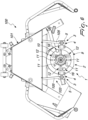
Figure 7 is a lateral elevation view of a portion of the machine ofFigure 5 ; -
Figures 7a and 7b are lateral elevation views of the device according to the invention shown inFigure 7 , in different conditions of operation; -
Figure 8 is a front elevation view of the device according to the invention applied to a suspension in a second configuration of use. - With reference to the figures, an anchoring device for spring-damper assemblies for machines for mounting/removing vehicle suspensions is generally designated by the
reference numeral 1. - The
device 1 is designed, during use, to be applied to aconventional machine 100 for the mounting/removing of vehicle suspensions. - Such suspensions essentially consist of a spring-damper assembly G constituted by a helical spring M the turns of which are wound around the movable stem of a shock absorber A and which is interposed between a plate P, which is integral with the external jacket of said shock absorber, and an abutment element R associated with the movable stem.
- The
machine 100 is of the type comprising aframe 101 for supporting alower assembly 102 for the support of the spring/damper assembly and anupper assembly 103 for the compression/release of the spring M which comprises acrossmember 104 which supports a pair oforientable arms 105 and can move with an alternating translational motion along two substantiallyvertical guides 106 associated with theframe 101. - In the present description, the term "substantially" is understood to mean except for the usual machining and assembly tolerances of the component parts.
- The
arms 105 are supported by thecrossmember 104 and are associated so as they can rotate about theguides 106 so as to be able to modify their orientation and therefore the distance of the corresponding ends. - The
crossmember 104 is associated with play with theguides 106, according to a constructive method known to the person skilled in the art, so as to be able to vary its own inclination with respect to them by a predefined maximum angle, so as to allow themachine 1 to adapt to different positions of the spring-damper assembly G. - The
arms 105 are provided withpins 108 which protrude in a lower region from the corresponding ends for connection to traditional vices or to other accessories for the anchoring of the upper part of the spring M of the spring-damper assembly G on which it is necessary to work. - The
machine 1 provides actuation means 107 for the movement, with an alternating translational motion, of thecrossmember 104, which are conventionally constituted by a pneumatic cylinder the stem of which is associated with said crossmember and the jacket of which is supported by theframe 101. - The shape and operation of the
machine 1 are not described in detail since they are known to the person skilled in the art. - The
device 1 comprises acoupling assembly 2 which can be associated with the upper abutment element R of the spring M of the spring-damper assembly G and means 3 for temporary or reversible connection to thearms 105 of themachine 1. - The
device 1 is adapted to be applied to themachine 1 by connecting it to thearms 105 in case one has to work on spring-damper assemblies G that entail compressing/releasing the spring M by means of the corresponding upper abutment element R, replacing conventional vices or other dedicated accessories of the known type. - Such connection means 3 provide a
joint 4 which can be associated in a reversible manner with each one of thearms 105 by means of thecorresponding pin 108, which are provided with two degrees of freedom in rotation about respective rotation axes which are substantially mutually perpendicular. - Each
joint 4 comprises abushing 5 which is extended along a first axis A1 and is associated with thecoupling assembly 2 so that it can rotate about a second axis A2 that is substantially perpendicular to the first axis A1 and not coplanar with respect to it, and acylinder 6 inserted within thebushing 5 and provided with aseat 7 for the insertion of thepin 108 of thecorresponding arm 105. Theseat 7 is extended along a third axis A3 which is substantially perpendicular to the first and second axes A1 and A2. Thebushing 5 is provided with anelongated slot 8 so as to allow an arc of relative rotation between thebushing 5 and thecylinder 6 about the first axis A1. - During use, the
device 1 is arranged so that the first and the second axes A1 and A2 are substantially horizontal and the third axis A3 is substantially vertical. - The first axes A1 of the two
joints 4 are substantially mutually parallel. During use, when thejoints 4 are arranged at the same level, the corresponding first axes A1 are aligned. The second axes A2 of thejoints 4 are substantially mutually parallel. - When the
device 1 is mounted on themachine 100 thejoints 4 allow, therefore, thecoupling assembly 2 to modify its own orientation by means of a rotation about the first axes A1 (Figures 7, 7a, 7b ) and/or by means of a rotation about the second axes A2 (Figures 5 ,5a and 5b ) to adapt to different shapes and arrangements of the spring-damper assembly G and of the corresponding upper abutment element R. - When, during use, a rotation of the
coupling assembly 2 about the second axes A2 is necessary, the coupling with play of thecrossmember 104 to theguides 106 makes it possible to compensate for the consequent misalignment in the vertical direction of thejoints 4 and of the correspondingarms 105. - Furthermore, the
coupling assembly 2 comprises anannular flange 9 which is hinged to thebushings 5 and acoupling plate 10 associated rotatably within said flange. Thecoupling plate 10 also has an annular shape. - The
coupling plate 10 has a plurality ofopenings 11, which are variously shaped and distributed thereon. Theopenings 11 pass through the thickness of thecoupling plate 10 so as to allow the selective insertion of threadedelements 12 for connection to the abutment element R of the spring-damper assembly G on which it is necessary to work. - By manually turning the
coupling plate 10 with respect to theflange 9 it is possible to position some of theopenings 11 at the holes usually provided on the abutment element R in order to be able to insert the threadedelements 12 so as to render thedevice 1 integral, by means of thecoupling plate 10, with said abutment element R and allow the compression/release of the spring M in safe conditions. - The geometry and arrangement of the
individual openings 11 on thecoupling plate 10 are such as to optimize the flexibility of use of thedevice 1 as the type of spring-damper assembly G on which it is necessary to work varies. - The
flange 9 is provided in diametrically opposite positions with two pairs ofeyes 13 for the insertion ofrespective pivots 14 arranged along the second axes A2 and passing through correspondingholes 15 formed in thebushings 5. Eachpivot 14 is locked axially byelastic rings 23 engaged inannular grooves 24, adapted to abut on opposite sides of theeyes 13. - In this manner each joint 4 is articulated to the
flange 9 about the respective second axis A2. - Means 16 are also provided for temporarily locking the angular position of the
coupling plate 10 with respect to theflange 9. - Such temporary locking means 16 can provide, for example, one or more, preferably two, threaded
knobs 17 adapted to engage in corresponding threadedholes 18 provided in diametrically opposite parts of thecoupling plate 10 in order to be clamped against theflange 9 to prevent the relative rotation of said plate with respect to it. - In greater detail, the
coupling plate 10 is provided with aninternal band 19, in which theopenings 11 are distributed, and with a loweredexternal band 20, between theinternal band 19 and theexternal band 20 there being anannular profile 21 coupled slidingly to theinternal edge 9a of theflange 9. Theinternal band 19 protrudes inside theannular flange 9 and theexternal band 20 abuts below said flange. - The
internal band 19 of thecoupling plate 10 remains recessed within theflange 9. - Furthermore, the
device 1 comprisesspacers 22 adapted to be associated with the threadedelements 12 and to be interposed between thecoupling plate 10 and the abutment element R in order to allow a stable anchoring thereof regardless of the shape of said element. -
Such spacers 22 are provided with a through hole to fit them along the stem of the threadedelements 12. - Between the head of the threaded
elements 12 and theinternal band 19 there are preferablywashers 25 having an elongated shape in order to ensure a stable connection. - In the embodiment shown there are three threaded
elements 12, with correspondingwashers 25, adapted to be inserted inrespective openings 11 selected from those provided on theinternal band 19 of thecoupling plate 10 as a function of the type of spring-damper assembly G on which it is necessary to work. -
Figures 5-7b show amachine 100 of the type described above in which thedevice 1 is applied to a spring-damper assembly G in a first configuration of use which does not provide for the use of thespacers 22 and of thewashers 25. - In
Figure 8 , thedevice 1 is applied to a different spring-damper assembly G which instead requires the use ofspacers 22 andwashers 25. - In practice it has been found that the described invention achieves the intended aim and objects and in particular it is pointed out that the device according to the invention, due to the different arrangements of the coupling assembly allowed by the particular means for connecting to the machine that are used, makes it possible to work on a broad range of spring-damper assemblies in optimum safety conditions.
- The shape of the coupling assembly, with the possibility to orient the coupling plate with respect to the flange and the variety of openings present on said plate, increases further the flexibility of use of the device according to the invention.
- The invention thus conceived is susceptible of numerous modifications and variations, all of which are within the scope of the appended claims.
- Where technical features mentioned in any claim are followed by reference signs, those reference signs have been included for the sole purpose of increasing the intelligibility of the claims and accordingly such reference signs do not have any limiting effect on the interpretation of each element identified by way of example by such reference signs.
Claims (7)
- An anchoring device (1) for spring-damper assemblies for machines for mounting/removing vehicle suspensions, machine (100) of the type comprising a frame (101) for supporting a lower assembly (102) for the support of the spring/damper assembly (G) and an upper assembly (103) for the compression/release of the spring (M) which comprises a crossmember (104) which supports a pair of orientable arms (105) which can move with an alternating translational motion along at least two substantially vertical guides (106) associated with the frame (101), said device (1) comprising a coupling assembly (2) which can be associated with an upper abutment element (R) of the spring (M) of the spring-damper assembly (G) and means (3) for connecting said coupling assembly (2) to said arms (105), said connection means (3) comprising a pair of joints (4) each of which can be associated with each one of said arms (105) and is provided with two degrees of freedom in rotation about respective rotation axes (A1, A2) which are mutually substantially perpendicular, characterized in that each one of said joints (4) comprises a bushing (5) which is extended along a first axis (A1) and is associated with said coupling assembly (2) so that it can rotate about a second axis (A2) that is substantially perpendicular to said first axis (A1), a cylinder (6) accommodated within said bushing (5) and provided with a seat (7) for the insertion of a pin (108) for fixing to the respective arm (105), the seat (7) being extended along a third axis (A3) that is substantially perpendicular to the first and second axes (A1, A2) and the bushing (5) being provided with an elongated slot (8) so as to allow an arc of relative rotation between the bushing (5) and the cylinder (6) about said first axis (A1).
- The device (1) according to claim 1, characterized in that the first axes (A1) of said two joints (4) are arranged substantially parallel to each other.
- The device (1) according to one or more of the preceding claims, characterized in that said coupling assembly (2) comprises an annular flange (9) associated with said bushings (5) and a coupling plate (10) associated rotatably within said flange (9), the coupling plate (10) being provided with a plurality of openings (11) for the selective insertion of threaded elements (12) for connection to the abutment element (R) of the spring-damper assembly (G).
- The device (1) according to claim 3, characterized in that it comprises means (16) for temporarily locking the angular position of said coupling plate (10) with respect to said flange (9).
- The device (1) according to claim 3, characterized in that said coupling plate (10) is provided with an internal band (19) in which said openings (11) are distributed and with a lowered external band (20), an annular profile (21) being formed between the internal band (19) and the external band (20) and being coupled slidingly with the internal edge (9a) of said flange (9), the internal band (19) protruding inside the flange (9) and the external band (20) abutting below said flange.
- The device (1) according to claim 3, characterized in that it comprises spacers (22) adapted to be associated with said threaded elements (12) and to be interposed between the coupling plate (10) and the abutment element (R) of the spring-damper assembly (G).
- A machine (100) for mounting/removing vehicle suspensions, comprising a frame (101) for supporting a lower assembly (102) for supporting the spring-damper assembly (G) and an upper assembly (103) for the compression/release of the spring (M) which comprises a crossmember (104) which supports a pair of orientable arms (105) and can move with an alternating translational motion along two substantially vertical guides (106) associated with said frame (101), the crossmember (104) being associated with play with said guides (106) so as to be able to vary its arrangement with respect to them, characterized in that it comprises a device (1) according to one or more of claims 1-6 having the corresponding joints (4) associated with said arms (105).
Applications Claiming Priority (1)
| Application Number | Priority Date | Filing Date | Title |
|---|---|---|---|
| IT202100001688 | 2021-01-28 |
Publications (3)
| Publication Number | Publication Date |
|---|---|
| EP4035835A1 EP4035835A1 (en) | 2022-08-03 |
| EP4035835C0 EP4035835C0 (en) | 2024-09-04 |
| EP4035835B1 true EP4035835B1 (en) | 2024-09-04 |
Family
ID=75439276
Family Applications (1)
| Application Number | Title | Priority Date | Filing Date |
|---|---|---|---|
| EP21217034.4A Active EP4035835B1 (en) | 2021-01-28 | 2021-12-22 | Anchoring device for spring-damper assemblies for machines for mounting/removing vehicle suspensions |
Country Status (3)
| Country | Link |
|---|---|
| EP (1) | EP4035835B1 (en) |
| ES (1) | ES2999066T3 (en) |
| PL (1) | PL4035835T3 (en) |
Family Cites Families (4)
| Publication number | Priority date | Publication date | Assignee | Title |
|---|---|---|---|---|
| FR2790986A1 (en) * | 1999-03-19 | 2000-09-22 | Michelin & Cie | METHOD AND DEVICE FOR PRECISE MOUNTING OF A MAC PHERSON SUSPENSION FORCE LEG |
| DE202006014178U1 (en) * | 2006-09-12 | 2006-11-23 | Klann-Spezial-Werkzeugbau-Gmbh | Spiral spring compressing unit comprises end plates on connecting rods, one end of spring being attached to pressure plate, while other is attached to mounting with centering pin whose angle can be adjusted to that of last winding on spring |
| TW201006709A (en) * | 2008-08-13 | 2010-02-16 | zhi-sheng Zhang | Portable shock absorber disassembling device |
| DE202012005626U1 (en) | 2012-06-06 | 2012-06-29 | Klann-Spezial-Werkzeugbau-Gmbh | Pressure plate for spring tensioner |
-
2021
- 2021-12-22 PL PL21217034.4T patent/PL4035835T3/en unknown
- 2021-12-22 ES ES21217034T patent/ES2999066T3/en active Active
- 2021-12-22 EP EP21217034.4A patent/EP4035835B1/en active Active
Also Published As
| Publication number | Publication date |
|---|---|
| PL4035835T3 (en) | 2025-02-03 |
| EP4035835C0 (en) | 2024-09-04 |
| EP4035835A1 (en) | 2022-08-03 |
| ES2999066T3 (en) | 2025-02-24 |
Similar Documents
| Publication | Publication Date | Title |
|---|---|---|
| US3814382A (en) | Spring compressor | |
| US4267896A (en) | Method and apparatus for aligning automobile suspension members | |
| US5680686A (en) | Strut spring compressor having floating compression head | |
| US4558500A (en) | Spring compressor for MacPherson strut suspension assemblies | |
| US12162089B2 (en) | Manual universal punching/welding apparatus and method | |
| CN107953733B (en) | tire changing machine | |
| EP4373680B1 (en) | An adjusting device for adjusting the camber angle for a suspension of a motor vehicle | |
| EP4035835B1 (en) | Anchoring device for spring-damper assemblies for machines for mounting/removing vehicle suspensions | |
| EP2524820B1 (en) | Machine for fitting and removing wheel tyres for vehicles | |
| EP2735405B1 (en) | An improved press for the reversible disassembling of car shock absorbers | |
| US4785519A (en) | Strut spring compressor | |
| CN107097064B (en) | Piston dismounting device of oil pressure damper | |
| CN113977228B (en) | Press-fitting device and press-fitting method for rubber nodes in connecting rod piece | |
| KR20150089410A (en) | Variable adapter for bushing replacement work | |
| EP3738715B1 (en) | Device for supporting spring-damper assemblies for machines for assembling/disassembling vehicle suspensions | |
| US4237594A (en) | Coil spring compressing tool | |
| EP3263279B1 (en) | Machine for assembling/disassembling spring/damper units of suspensions of vehicles having a simplified structure | |
| EP1214176B1 (en) | A device for the dismantling and reassembly of vehicle-suspension spring/shock-absorber units | |
| CN112658671A (en) | Industrial production is with automatic intelligent control device | |
| US2296162A (en) | Quick acting clamp | |
| CN115156793B (en) | Quick change device for robot welding fixture | |
| CN215153771U (en) | Height adjusting device | |
| US5099757A (en) | Spring rate control in a screen printing device | |
| CN113681480A (en) | A tooling fixture for auto parts | |
| EP4173760B1 (en) | Supporting fixture for assembling/disassembling the gearbox of vehicles with increased operating flexibility |
Legal Events
| Date | Code | Title | Description |
|---|---|---|---|
| PUAI | Public reference made under article 153(3) epc to a published international application that has entered the european phase |
Free format text: ORIGINAL CODE: 0009012 |
|
| STAA | Information on the status of an ep patent application or granted ep patent |
Free format text: STATUS: THE APPLICATION HAS BEEN PUBLISHED |
|
| AK | Designated contracting states |
Kind code of ref document: A1 Designated state(s): AL AT BE BG CH CY CZ DE DK EE ES FI FR GB GR HR HU IE IS IT LI LT LU LV MC MK MT NL NO PL PT RO RS SE SI SK SM TR |
|
| STAA | Information on the status of an ep patent application or granted ep patent |
Free format text: STATUS: REQUEST FOR EXAMINATION WAS MADE |
|
| 17P | Request for examination filed |
Effective date: 20221025 |
|
| RBV | Designated contracting states (corrected) |
Designated state(s): AL AT BE BG CH CY CZ DE DK EE ES FI FR GB GR HR HU IE IS IT LI LT LU LV MC MK MT NL NO PL PT RO RS SE SI SK SM TR |
|
| P01 | Opt-out of the competence of the unified patent court (upc) registered |
Effective date: 20230528 |
|
| GRAP | Despatch of communication of intention to grant a patent |
Free format text: ORIGINAL CODE: EPIDOSNIGR1 |
|
| STAA | Information on the status of an ep patent application or granted ep patent |
Free format text: STATUS: GRANT OF PATENT IS INTENDED |
|
| INTG | Intention to grant announced |
Effective date: 20240405 |
|
| GRAS | Grant fee paid |
Free format text: ORIGINAL CODE: EPIDOSNIGR3 |
|
| GRAA | (expected) grant |
Free format text: ORIGINAL CODE: 0009210 |
|
| STAA | Information on the status of an ep patent application or granted ep patent |
Free format text: STATUS: THE PATENT HAS BEEN GRANTED |
|
| AK | Designated contracting states |
Kind code of ref document: B1 Designated state(s): AL AT BE BG CH CY CZ DE DK EE ES FI FR GB GR HR HU IE IS IT LI LT LU LV MC MK MT NL NO PL PT RO RS SE SI SK SM TR |
|
| REG | Reference to a national code |
Ref country code: GB Ref legal event code: FG4D |
|
| REG | Reference to a national code |
Ref country code: CH Ref legal event code: EP |
|
| REG | Reference to a national code |
Ref country code: IE Ref legal event code: FG4D |
|
| REG | Reference to a national code |
Ref country code: DE Ref legal event code: R096 Ref document number: 602021018263 Country of ref document: DE |
|
| U01 | Request for unitary effect filed |
Effective date: 20240926 |
|
| U07 | Unitary effect registered |
Designated state(s): AT BE BG DE DK EE FI FR IT LT LU LV MT NL PT RO SE SI Effective date: 20241021 |
|
| P04 | Withdrawal of opt-out of the competence of the unified patent court (upc) registered |
Free format text: CASE NUMBER: APP_56630/2024 Effective date: 20241016 |
|
| PG25 | Lapsed in a contracting state [announced via postgrant information from national office to epo] |
Ref country code: NO Free format text: LAPSE BECAUSE OF FAILURE TO SUBMIT A TRANSLATION OF THE DESCRIPTION OR TO PAY THE FEE WITHIN THE PRESCRIBED TIME-LIMIT Effective date: 20241204 |
|
| PG25 | Lapsed in a contracting state [announced via postgrant information from national office to epo] |
Ref country code: GR Free format text: LAPSE BECAUSE OF FAILURE TO SUBMIT A TRANSLATION OF THE DESCRIPTION OR TO PAY THE FEE WITHIN THE PRESCRIBED TIME-LIMIT Effective date: 20241205 |
|
| U20 | Renewal fee for the european patent with unitary effect paid |
Year of fee payment: 4 Effective date: 20241218 |
|
| PG25 | Lapsed in a contracting state [announced via postgrant information from national office to epo] |
Ref country code: HR Free format text: LAPSE BECAUSE OF FAILURE TO SUBMIT A TRANSLATION OF THE DESCRIPTION OR TO PAY THE FEE WITHIN THE PRESCRIBED TIME-LIMIT Effective date: 20240904 |
|
| PG25 | Lapsed in a contracting state [announced via postgrant information from national office to epo] |
Ref country code: RS Free format text: LAPSE BECAUSE OF FAILURE TO SUBMIT A TRANSLATION OF THE DESCRIPTION OR TO PAY THE FEE WITHIN THE PRESCRIBED TIME-LIMIT Effective date: 20241204 |
|
| PG25 | Lapsed in a contracting state [announced via postgrant information from national office to epo] |
Ref country code: RS Free format text: LAPSE BECAUSE OF FAILURE TO SUBMIT A TRANSLATION OF THE DESCRIPTION OR TO PAY THE FEE WITHIN THE PRESCRIBED TIME-LIMIT Effective date: 20241204 Ref country code: NO Free format text: LAPSE BECAUSE OF FAILURE TO SUBMIT A TRANSLATION OF THE DESCRIPTION OR TO PAY THE FEE WITHIN THE PRESCRIBED TIME-LIMIT Effective date: 20241204 Ref country code: HR Free format text: LAPSE BECAUSE OF FAILURE TO SUBMIT A TRANSLATION OF THE DESCRIPTION OR TO PAY THE FEE WITHIN THE PRESCRIBED TIME-LIMIT Effective date: 20240904 Ref country code: GR Free format text: LAPSE BECAUSE OF FAILURE TO SUBMIT A TRANSLATION OF THE DESCRIPTION OR TO PAY THE FEE WITHIN THE PRESCRIBED TIME-LIMIT Effective date: 20241205 |
|
| REG | Reference to a national code |
Ref country code: ES Ref legal event code: FG2A Ref document number: 2999066 Country of ref document: ES Kind code of ref document: T3 Effective date: 20250224 |
|
| PG25 | Lapsed in a contracting state [announced via postgrant information from national office to epo] |
Ref country code: IS Free format text: LAPSE BECAUSE OF FAILURE TO SUBMIT A TRANSLATION OF THE DESCRIPTION OR TO PAY THE FEE WITHIN THE PRESCRIBED TIME-LIMIT Effective date: 20250104 |
|
| PG25 | Lapsed in a contracting state [announced via postgrant information from national office to epo] |
Ref country code: SM Free format text: LAPSE BECAUSE OF FAILURE TO SUBMIT A TRANSLATION OF THE DESCRIPTION OR TO PAY THE FEE WITHIN THE PRESCRIBED TIME-LIMIT Effective date: 20240904 |
|
| PG25 | Lapsed in a contracting state [announced via postgrant information from national office to epo] |
Ref country code: CZ Free format text: LAPSE BECAUSE OF FAILURE TO SUBMIT A TRANSLATION OF THE DESCRIPTION OR TO PAY THE FEE WITHIN THE PRESCRIBED TIME-LIMIT Effective date: 20240904 |
|
| PG25 | Lapsed in a contracting state [announced via postgrant information from national office to epo] |
Ref country code: SK Free format text: LAPSE BECAUSE OF FAILURE TO SUBMIT A TRANSLATION OF THE DESCRIPTION OR TO PAY THE FEE WITHIN THE PRESCRIBED TIME-LIMIT Effective date: 20240904 |
|
| PG25 | Lapsed in a contracting state [announced via postgrant information from national office to epo] |
Ref country code: MC Free format text: LAPSE BECAUSE OF FAILURE TO SUBMIT A TRANSLATION OF THE DESCRIPTION OR TO PAY THE FEE WITHIN THE PRESCRIBED TIME-LIMIT Effective date: 20240904 |
|
| PLBE | No opposition filed within time limit |
Free format text: ORIGINAL CODE: 0009261 |
|
| STAA | Information on the status of an ep patent application or granted ep patent |
Free format text: STATUS: NO OPPOSITION FILED WITHIN TIME LIMIT |
|
| REG | Reference to a national code |
Ref country code: CH Ref legal event code: PL |
|
| 26N | No opposition filed |
Effective date: 20250605 |
|
| PG25 | Lapsed in a contracting state [announced via postgrant information from national office to epo] |
Ref country code: CH Free format text: LAPSE BECAUSE OF NON-PAYMENT OF DUE FEES Effective date: 20241231 |
|
| PG25 | Lapsed in a contracting state [announced via postgrant information from national office to epo] |
Ref country code: IE Free format text: LAPSE BECAUSE OF NON-PAYMENT OF DUE FEES Effective date: 20241222 |
|
| PGFP | Annual fee paid to national office [announced via postgrant information from national office to epo] |
Ref country code: GB Payment date: 20251218 Year of fee payment: 5 |
|
| U20 | Renewal fee for the european patent with unitary effect paid |
Year of fee payment: 5 Effective date: 20251218 |
|
| PGFP | Annual fee paid to national office [announced via postgrant information from national office to epo] |
Ref country code: PL Payment date: 20251212 Year of fee payment: 5 |
|
| PGFP | Annual fee paid to national office [announced via postgrant information from national office to epo] |
Ref country code: ES Payment date: 20260105 Year of fee payment: 5 |