EP4035830A1 - Sanding machine for sanding/finishing panels made of wood, metal, plastic or the like - Google Patents
Sanding machine for sanding/finishing panels made of wood, metal, plastic or the like Download PDFInfo
- Publication number
- EP4035830A1 EP4035830A1 EP22153663.4A EP22153663A EP4035830A1 EP 4035830 A1 EP4035830 A1 EP 4035830A1 EP 22153663 A EP22153663 A EP 22153663A EP 4035830 A1 EP4035830 A1 EP 4035830A1
- Authority
- EP
- European Patent Office
- Prior art keywords
- sanding
- sanding machine
- machine according
- abrasive belt
- belt
- Prior art date
- Legal status (The legal status is an assumption and is not a legal conclusion. Google has not performed a legal analysis and makes no representation as to the accuracy of the status listed.)
- Granted
Links
Images


Classifications
-
- B—PERFORMING OPERATIONS; TRANSPORTING
- B24—GRINDING; POLISHING
- B24B—MACHINES, DEVICES, OR PROCESSES FOR GRINDING OR POLISHING; DRESSING OR CONDITIONING OF ABRADING SURFACES; FEEDING OF GRINDING, POLISHING, OR LAPPING AGENTS
- B24B21/00—Machines or devices using grinding or polishing belts; Accessories therefor
- B24B21/04—Machines or devices using grinding or polishing belts; Accessories therefor for grinding plane surfaces
- B24B21/10—Machines or devices using grinding or polishing belts; Accessories therefor for grinding plane surfaces involving a rigid member, e.g. pressure bar, table, pressing or supporting the belt over substantially its whole span
-
- B—PERFORMING OPERATIONS; TRANSPORTING
- B24—GRINDING; POLISHING
- B24B—MACHINES, DEVICES, OR PROCESSES FOR GRINDING OR POLISHING; DRESSING OR CONDITIONING OF ABRADING SURFACES; FEEDING OF GRINDING, POLISHING, OR LAPPING AGENTS
- B24B7/00—Machines or devices designed for grinding plane surfaces on work, including polishing plane glass surfaces; Accessories therefor
- B24B7/06—Machines or devices designed for grinding plane surfaces on work, including polishing plane glass surfaces; Accessories therefor involving conveyor belts, a sequence of travelling work-tables or the like
-
- B—PERFORMING OPERATIONS; TRANSPORTING
- B24—GRINDING; POLISHING
- B24B—MACHINES, DEVICES, OR PROCESSES FOR GRINDING OR POLISHING; DRESSING OR CONDITIONING OF ABRADING SURFACES; FEEDING OF GRINDING, POLISHING, OR LAPPING AGENTS
- B24B7/00—Machines or devices designed for grinding plane surfaces on work, including polishing plane glass surfaces; Accessories therefor
- B24B7/20—Machines or devices designed for grinding plane surfaces on work, including polishing plane glass surfaces; Accessories therefor characterised by a special design with respect to properties of the material of non-metallic articles to be ground
- B24B7/28—Machines or devices designed for grinding plane surfaces on work, including polishing plane glass surfaces; Accessories therefor characterised by a special design with respect to properties of the material of non-metallic articles to be ground for grinding wood
Definitions
- the invention relates to a sanding machine for sanding/finishing panels made of wood, metal, plastic or the like.
- a sanding machine which comprises a conveyor belt, which has an upper transport branch defining a substantially horizontal support surface for at least one panel and is designed to feed the panel in a first direction; and a sanding device, which is mounted above the support surface in order to sand an upper face of the panel.
- the sanding device comprises an abrasive belt, which is wound in a ring shape around a plurality of idler rollers and extends in a second direction, which is transverse to the first direction.
- the sanding device further comprises a plurality of thrust elements, which are distributed inside the abrasive belt in a third direction, which is inclined at angles other than 0° relative to the first direction and to the second direction, and have an active portion with a substantially rectangular shape acting upon the abrasive belt.
- the thrust elements are movable independently of one another in a fourth direction, which is orthogonal to the support surface, between respective lowered operating positions, in which the corresponding portions of abrasive belt are moved so as to come into contact with the upper face of the panel, and respective raised rest position, in which the corresponding portions of abrasive belt disengage the upper portion of the panel.
- the sanding machine further comprises an intermediate belt interposed between the thrust element and the abrasive belt.
- the intermediate belt is mounted inside the abrasive belt and is provided with a plurality of teeth, which project from the intermediate belt, are in contact with the abrasive belt in order to the reduce the surface of the abrasive belt in contact with the panel and define, together with the abrasive belt, a plurality of cooling channels, which are flown through by air suited to ensure the cooling of the abrasive belt.
- the sanding machine is further provided with a detection device to detect at least one geometrical feature of the panel.
- the detection device normally comprises a plurality of contact rollers, which are distributed above the support surface in the second direction and are mounted so as to rotate around respective rotation axes, which are parallel to the second direction.
- the contact rollers arranged inside the moving path of the panel are lifted from the panel so as to allow the detection device to detect the width of the panel in the second direction and/or the presence of possible openings made in panels used as, for example, frames for doors and/or windows.
- the active portion of each thrust element has a width, measured parallel to the third direction, which is smaller than a width, measured parallel to the second direction, of the portion of abrasive belt and, hence, of panel engaged by the active portion.
- the object of the invention is to provide a sanding machine for sanding/finishing panels made of wood, metal, plastic or the like, which does not suffer from the drawbacks described above and is simple and economic to be actuated.
- a sanding machine for sanding/finishing panels made of wood, metal, plastic or the like according to the appended claims.
- number 1 indicates, as a whole, a sanding machine for sanding/finishing panels 2 made of wood, metal, plastic or the like with a substantially parallelepiped-like shape.
- the panel 2 has at least one opening and is used, for example, as frame for doors and/or windows.
- the sanding machine 1 comprises a support frame 3 and a feeding device 4, which is mounted on the support frame 3 so as to move the panels 2 one after the other in a horizontal direction 5.
- the device 4 comprises a conveyor belt 6, which has an upper transport branch defining a horizontal support surface P for the panel 2 and is wound in a ring shape around a pair of motor-driven pulleys 7 so as to rotate, relative to the frame 3, around respective longitudinal axes 8, which are parallel to one another and to a horizontal direction 9, which is transverse to the direction 5.
- the conveyor belt 6 is eliminated and replaced by a plurality of motor-driven feeding rollers, which are mounted so as to rotate around respective rotation axes, which are parallel to the axis 9.
- the sanding machine 1 further comprises at least one sanding unit 10 comprising, in turn, an abrasive belt 11, which is wound in a ring shape around a plurality of idler rollers 12 (in this case, two rollers 12), which are mounted so as to rotate around respective longitudinal axes 13 parallel to a direction 14, which is oriented according to respective angles other than 0° relative to the direction 5 and to the direction 9.
- a sanding unit 10 comprising, in turn, an abrasive belt 11, which is wound in a ring shape around a plurality of idler rollers 12 (in this case, two rollers 12), which are mounted so as to rotate around respective longitudinal axes 13 parallel to a direction 14, which is oriented according to respective angles other than 0° relative to the direction 5 and to the direction 9.
- the belt 11 has a lower sanding branch 15, which is moved so as to come into contact with an upper face 16 of the panel 2 in ways that will be better described below and extends as well as is movable in a direction 17, which is transverse to the direction 14 and is oriented according to respective angles other than 0° relative to the direction 5 and to the direction 9.
- the unit 10 further comprises an intermediate belt 18, which is mounted inside the belt 11, extends as well as is movable in the direction 17 and is wound in a ring shape around a plurality of idler rollers 19 (in this case, two rollers 19), which are mounted so as to rotate around respective longitudinal axes 20, which are parallel to the axes 13 and to the direction 14.
- an intermediate belt 18 which is mounted inside the belt 11, extends as well as is movable in the direction 17 and is wound in a ring shape around a plurality of idler rollers 19 (in this case, two rollers 19), which are mounted so as to rotate around respective longitudinal axes 20, which are parallel to the axes 13 and to the direction 14.
- the belt 18 has a plurality of teeth 21 parallel to one another, which project from an outer surface of the belt 18 and face the belt 11.
- the belts 11 and 18 are operated by an operating device 22 comprising, in this case, an electric motor (which is not shown herein), a first belt transmission 23 to connect an output rod of the electric motor (which is not shown herein) and one of the rollers 12 to one another and a second belt transmission 24 to connect the motor-driven roller 12 and one of the rollers 19 to one another.
- an operating device 22 comprising, in this case, an electric motor (which is not shown herein), a first belt transmission 23 to connect an output rod of the electric motor (which is not shown herein) and one of the rollers 12 to one another and a second belt transmission 24 to connect the motor-driven roller 12 and one of the rollers 19 to one another.
- the lower branch 15 of the belt 11 is selectively moved so as to come into contact with the face 16 of the panel 2 by a thrust device 25, which is mounted inside the belt 18.
- the device 25 comprises, in particular, a plurality of thrust elements 26, which are distributed inside the belt 18 in the direction 9, are mounted above the branch 15 and are movable independently of one another in a vertical direction 27, which is orthogonal to the directions 5 and 9 and perpendicular to the surface P.
- Each element 26 has an active portion (which is not shown herein) with a substantially rectangular shape and is movable in the direction 27 between a lowered operating position, in which the active portion of the element 26 moves the belt 18 so that it comes into contact with the belt 11 and the belt 11 so that it comes into contact with the face 16, and a raised rest position, in which the belt 11 disengages the face 16.
- the teeth 21 of the belt 18 are moved so as to come into contact with the belt 11 in order to reduce the surface of the belt 11 in contact with the face 16 and define, together with the belt 11, a plurality of cooling channels (not shown herein), which are flown through by air suited to ensure the cooling of the belt 11.
- the width of the belt 11, measured parallel to the direction 14, is at least equal to twice the width of the active portion (not shown herein) of an element 26 measured parallel to the direction 5.
- the sanding machine 1 is further provided with a detection device 28, which is mounted above and on the input side of the surface P in order to detect at least one geometrical feature of the panel 2.
- the device 28 is a mechanical detection device, which is arranged upstream of the device 25 in the direction 5 and comprises a plurality of contact rollers 29, which are as many as the elements 26.
- rollers 29 are distributed above the surface P in the direction 9 and are mounted so as to rotate around respective rotation axes 30, which are parallel to the direction 9.
- the contact rollers 29 arranged inside the moving path of the panel 2 are lifted from the panel 2 so as to allow the detection device 28 to detect the width of the panel 2 in the direction 9 and/or the presence of openings (not shown herein) made in the panels 2 used as, for example, frames for doors and/or windows.
- Each element 26 is aligned with a corresponding roller 29 in the direction 5 and is associated with the corresponding roller 29 so as to move between its lowered operating position and its raised rest position in response to a signal of the roller 29.
- rollers 29 are eliminated and replaced by at least one detection device that is not in contact with the panels 2, for example an optical, inductive or capacitive device.
- each element 26 Since the elements 26 are distributed in the direction 9, the active portion (which is not shown herein) of each element 26 has a width, measured parallel to the direction 9, which is equal to a width, also measured parallel to the direction 9, of the portion of belt 11 and, hence, of panel 2 engaged by the active portion itself (which is not shown herein) and the sanding machine 1 has a relatively high processing precision, in particular in the area of the longitudinal edges of the face 16 parallel to the direction 5.
- both the elements 26 and the rollers 29 are distributed above the surface P in the direction 9, both the distances between the elements 26 and the relative rollers 29 and the time intervals between the detection of the rollers 29 and the movements of the corresponding elements 26 to their lowered operating positions are equal to one another.
- the sanding machine 1 is provided with an electronic control unit 31, which is configured to calculate one single time interval and, therefore, is relatively simple and economic.
- the sanding machine 1 comprises a further sanding unit 32, which is arranged between the detection device 28 and the unit 10 and is completely equivalent to the unit 10.
- the sole difference between the unit 32 and the unit 10 lies in the fact that the branch 15 of the belt 11 of the unit 32 extends and is movable in a direction 33 converging towards the direction 17.
- the belt 11 of the unit 10 is movable in a clockwise direction and the belt 11 of the unit 32 is movable in a counterclockwise direction.
- both the direction 17 and the direction 33 have a component that is parallel and contrary to the direction 5 and the sanding processing of the belts 11 of the two units 10 and 32 is oriented substantially crosswise to the direction 5.
- the variant shown in figure 3 is different from figure 2 in that, in the former, the branch 15 of the belt 11 of the unit 32 extends and is movable in a direction 34 parallel to the direction 17.
- the belt 11 of the unit 10 is movable in a clockwise direction and the belt 11 of the unit 32 is movable in a counterclockwise direction.
- the direction 17 has a component that is parallel and contrary to the direction 5
- the direction 34 has a component that is parallel to and concordant with the direction 5
- the sanding processing of the belt 11 of the unit 10 is oriented substantially crosswise to the direction 5
- the sanding processing of the belt 11 of the unit 32 is oriented according to a relatively large angle relative to the direction 9 and, therefore, the sanding machine 1 has a relatively high finishing of the faces 16 of the panels 2.
- the conveyor belt 6 is eliminated and replaced by a plurality of motor-driven feeding rollers, which are mounted so as to rotate around respective rotation axes, which are parallel to the axis 9, and the sanding machine 1 is further provided with at least one sanding unit completely equivalent to the units 10, 32 and mounted under the surface P in order to sand/finish a lower face of the panels 2.
Landscapes
- Engineering & Computer Science (AREA)
- Mechanical Engineering (AREA)
- Finish Polishing, Edge Sharpening, And Grinding By Specific Grinding Devices (AREA)
- Laminated Bodies (AREA)
- Dry Formation Of Fiberboard And The Like (AREA)
Abstract
Description
- This Patent Application claims priority from
Italian Patent Application No. 102021000001613 filed on January 27, 2021 - The invention relates to a sanding machine for sanding/finishing panels made of wood, metal, plastic or the like.
- When dealing with the sanding/finishing of panels made of wood, metal, plastic or the like, a sanding machine is known, which comprises a conveyor belt, which has an upper transport branch defining a substantially horizontal support surface for at least one panel and is designed to feed the panel in a first direction; and a sanding device, which is mounted above the support surface in order to sand an upper face of the panel.
- The sanding device comprises an abrasive belt, which is wound in a ring shape around a plurality of idler rollers and extends in a second direction, which is transverse to the first direction.
- The sanding device further comprises a plurality of thrust elements, which are distributed inside the abrasive belt in a third direction, which is inclined at angles other than 0° relative to the first direction and to the second direction, and have an active portion with a substantially rectangular shape acting upon the abrasive belt.
- The thrust elements are movable independently of one another in a fourth direction, which is orthogonal to the support surface, between respective lowered operating positions, in which the corresponding portions of abrasive belt are moved so as to come into contact with the upper face of the panel, and respective raised rest position, in which the corresponding portions of abrasive belt disengage the upper portion of the panel.
- Generally speaking, the sanding machine further comprises an intermediate belt interposed between the thrust element and the abrasive belt.
- The intermediate belt is mounted inside the abrasive belt and is provided with a plurality of teeth, which project from the intermediate belt, are in contact with the abrasive belt in order to the reduce the surface of the abrasive belt in contact with the panel and define, together with the abrasive belt, a plurality of cooling channels, which are flown through by air suited to ensure the cooling of the abrasive belt.
- The sanding machine is further provided with a detection device to detect at least one geometrical feature of the panel.
- The detection device normally comprises a plurality of contact rollers, which are distributed above the support surface in the second direction and are mounted so as to rotate around respective rotation axes, which are parallel to the second direction.
- Following the movement of the panel in the first direction, the contact rollers arranged inside the moving path of the panel are lifted from the panel so as to allow the detection device to detect the width of the panel in the second direction and/or the presence of possible openings made in panels used as, for example, frames for doors and/or windows.
- Since the thrust elements are distributed in the third direction, the active portion of each thrust element has a width, measured parallel to the third direction, which is smaller than a width, measured parallel to the second direction, of the portion of abrasive belt and, hence, of panel engaged by the active portion.
- As a consequence, known sanding machines for sanding/finishing of panels made of wood, metal, plastic or the like of the type described above suffer from a relatively small processing precision, in particular in the area of the longitudinal edges of the upper face of the panel parallel to the first direction.
- Furthermore, since:
- the contact rollers are distributed above the support surface in the second direction and the thrust elements are distributed inside the abrasive belt in the third direction, namely in directions that are inclined at an angle other than 0° relative to one another;
- the distances between the contact rollers and the relative thrust elements, measured parallel to the first direction, are different from one another; and
- each thrust element must be moved to its lowered operating position when the centre of gravity of the relative active portion is substantially coplanar to a front face of the panel;
- the time intervals between the detection of the contact rollers and the movements of the corresponding thrust elements to the relative lowered operating positions are all different from one another.
- As a consequence, known sanding machines for sanding/finishing of panels made of wood, metal, plastic or the like of the type described above must be provided with an electronic control unit, which is configured to calculate the aforesaid time intervals and, therefore, is relatively complicated and expensive.
- The object of the invention is to provide a sanding machine for sanding/finishing panels made of wood, metal, plastic or the like, which does not suffer from the drawbacks described above and is simple and economic to be actuated.
- According to the invention, there is provided a sanding machine for sanding/finishing panels made of wood, metal, plastic or the like according to the appended claims.
- The invention will now be described with reference to the accompanying drawings showing a non-limiting embodiment thereof, wherein:
-
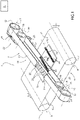
figure 1 is a schematic perspective view, with parts removed for greater clarity, of a preferred embodiment of the sanding machine according to the invention; -
figure 2 is a schematic perspective view, with parts removed for greater clarity, of a first variant of the sanding machine offigure 1 ; and -
figure 3 is a schematic perspective view, with parts removed for greater clarity, of a second variant of the sanding machine offigure 1 . - With reference to
figure 1 , number 1 indicates, as a whole, a sanding machine for sanding/finishing panels 2 made of wood, metal, plastic or the like with a substantially parallelepiped-like shape. - According to a variant which is not shown herein, the
panel 2 has at least one opening and is used, for example, as frame for doors and/or windows. - The sanding machine 1 comprises a support frame 3 and a feeding device 4, which is mounted on the support frame 3 so as to move the
panels 2 one after the other in ahorizontal direction 5. - The device 4 comprises a conveyor belt 6, which has an upper transport branch defining a horizontal support surface P for the
panel 2 and is wound in a ring shape around a pair of motor-drivenpulleys 7 so as to rotate, relative to the frame 3, around respectivelongitudinal axes 8, which are parallel to one another and to ahorizontal direction 9, which is transverse to thedirection 5. - According to a variant which is not shown herein, the conveyor belt 6 is eliminated and replaced by a plurality of motor-driven feeding rollers, which are mounted so as to rotate around respective rotation axes, which are parallel to the
axis 9. - The sanding machine 1 further comprises at least one
sanding unit 10 comprising, in turn, anabrasive belt 11, which is wound in a ring shape around a plurality of idler rollers 12 (in this case, two rollers 12), which are mounted so as to rotate around respectivelongitudinal axes 13 parallel to adirection 14, which is oriented according to respective angles other than 0° relative to thedirection 5 and to thedirection 9. - The
belt 11 has alower sanding branch 15, which is moved so as to come into contact with anupper face 16 of thepanel 2 in ways that will be better described below and extends as well as is movable in adirection 17, which is transverse to thedirection 14 and is oriented according to respective angles other than 0° relative to thedirection 5 and to thedirection 9. - The
unit 10 further comprises anintermediate belt 18, which is mounted inside thebelt 11, extends as well as is movable in thedirection 17 and is wound in a ring shape around a plurality of idler rollers 19 (in this case, two rollers 19), which are mounted so as to rotate around respectivelongitudinal axes 20, which are parallel to theaxes 13 and to thedirection 14. - The
belt 18 has a plurality ofteeth 21 parallel to one another, which project from an outer surface of thebelt 18 and face thebelt 11. - The
belts operating device 22 comprising, in this case, an electric motor (which is not shown herein), afirst belt transmission 23 to connect an output rod of the electric motor (which is not shown herein) and one of therollers 12 to one another and asecond belt transmission 24 to connect the motor-drivenroller 12 and one of therollers 19 to one another. - The
lower branch 15 of thebelt 11 is selectively moved so as to come into contact with theface 16 of thepanel 2 by athrust device 25, which is mounted inside thebelt 18. - The
device 25 comprises, in particular, a plurality ofthrust elements 26, which are distributed inside thebelt 18 in thedirection 9, are mounted above thebranch 15 and are movable independently of one another in avertical direction 27, which is orthogonal to thedirections - Each
element 26 has an active portion (which is not shown herein) with a substantially rectangular shape and is movable in thedirection 27 between a lowered operating position, in which the active portion of theelement 26 moves thebelt 18 so that it comes into contact with thebelt 11 and thebelt 11 so that it comes into contact with theface 16, and a raised rest position, in which thebelt 11 disengages theface 16. - Following the movement of the
elements 26 to their lowered operating position, theteeth 21 of thebelt 18 are moved so as to come into contact with thebelt 11 in order to reduce the surface of thebelt 11 in contact with theface 16 and define, together with thebelt 11, a plurality of cooling channels (not shown herein), which are flown through by air suited to ensure the cooling of thebelt 11. - With regard to the information disclosed above, it should be pointed out that the width of the
belt 11, measured parallel to thedirection 14, is at least equal to twice the width of the active portion (not shown herein) of anelement 26 measured parallel to thedirection 5. - The sanding machine 1 is further provided with a
detection device 28, which is mounted above and on the input side of the surface P in order to detect at least one geometrical feature of thepanel 2. - In this case, the
device 28 is a mechanical detection device, which is arranged upstream of thedevice 25 in thedirection 5 and comprises a plurality ofcontact rollers 29, which are as many as theelements 26. - The
rollers 29 are distributed above the surface P in thedirection 9 and are mounted so as to rotate aroundrespective rotation axes 30, which are parallel to thedirection 9. - Following the movement of the
panel 2 in thedirection 5, thecontact rollers 29 arranged inside the moving path of thepanel 2 are lifted from thepanel 2 so as to allow thedetection device 28 to detect the width of thepanel 2 in thedirection 9 and/or the presence of openings (not shown herein) made in thepanels 2 used as, for example, frames for doors and/or windows. - Each
element 26 is aligned with acorresponding roller 29 in thedirection 5 and is associated with thecorresponding roller 29 so as to move between its lowered operating position and its raised rest position in response to a signal of theroller 29. - According to a variant which is not shown herein, the
rollers 29 are eliminated and replaced by at least one detection device that is not in contact with thepanels 2, for example an optical, inductive or capacitive device. - Since the
elements 26 are distributed in thedirection 9, the active portion (which is not shown herein) of eachelement 26 has a width, measured parallel to thedirection 9, which is equal to a width, also measured parallel to thedirection 9, of the portion ofbelt 11 and, hence, ofpanel 2 engaged by the active portion itself (which is not shown herein) and the sanding machine 1 has a relatively high processing precision, in particular in the area of the longitudinal edges of theface 16 parallel to thedirection 5. - Furthermore, since both the
elements 26 and therollers 29 are distributed above the surface P in thedirection 9, both the distances between theelements 26 and therelative rollers 29 and the time intervals between the detection of therollers 29 and the movements of thecorresponding elements 26 to their lowered operating positions are equal to one another. - As a consequence, the sanding machine 1 is provided with an
electronic control unit 31, which is configured to calculate one single time interval and, therefore, is relatively simple and economic. - The variant shown in
figure 2 is different fromfigure 1 in that, in the former, the sanding machine 1 comprises afurther sanding unit 32, which is arranged between thedetection device 28 and theunit 10 and is completely equivalent to theunit 10. - The sole difference between the
unit 32 and theunit 10 lies in the fact that thebranch 15 of thebelt 11 of theunit 32 extends and is movable in adirection 33 converging towards thedirection 17. - In particular, the
belt 11 of theunit 10 is movable in a clockwise direction and thebelt 11 of theunit 32 is movable in a counterclockwise direction. As a consequence, both thedirection 17 and thedirection 33 have a component that is parallel and contrary to thedirection 5 and the sanding processing of thebelts 11 of the twounits direction 5. - The variant shown in
figure 3 is different fromfigure 2 in that, in the former, thebranch 15 of thebelt 11 of theunit 32 extends and is movable in adirection 34 parallel to thedirection 17. - In particular, the
belt 11 of theunit 10 is movable in a clockwise direction and thebelt 11 of theunit 32 is movable in a counterclockwise direction. As a consequence, thedirection 17 has a component that is parallel and contrary to thedirection 5, thedirection 34 has a component that is parallel to and concordant with thedirection 5, the sanding processing of thebelt 11 of theunit 10 is oriented substantially crosswise to thedirection 5, the sanding processing of thebelt 11 of theunit 32 is oriented according to a relatively large angle relative to thedirection 9 and, therefore, the sanding machine 1 has a relatively high finishing of thefaces 16 of thepanels 2. - According to a variant which is not shown herein, the conveyor belt 6 is eliminated and replaced by a plurality of motor-driven feeding rollers, which are mounted so as to rotate around respective rotation axes, which are parallel to the
axis 9, and the sanding machine 1 is further provided with at least one sanding unit completely equivalent to theunits panels 2.
Claims (16)
- A sanding machine for sanding/finishing panels (2) made of wood, metal, plastic or the like, the sanding machine comprising a feeding device (4), which defines a support surface (P) for at least one panel (2) and is designed to feed the panel (2) in a first direction (5); at least one first sanding device (10), which is mounted above or under the support surface (P) and comprises, in turn, a first abrasive belt (11), which is wound in a ring shape around a plurality of idler rollers (12) so as to sand a face (16) of the panel (2); a plurality of first thrust elements (26), which are distributed inside the first abrasive belt (11) in a second direction (9), which is transverse to the first direction (5) and parallel to the support surface (P); and being characterized in that the first abrasive belt (11) has a sanding segment (15), which is in contact with the face (16) and extends as well as is movable in a third direction (17), which is parallel to the support surface (P) and is inclined at angles other than 0° relative to said first and second directions (5, 9).
- The sanding machine according to claim 1 and further comprising a detection unit (28), which is mounted upstream of the first thrust elements (26) in the first direction (5) in order to detect at least one geometrical feature of the panel (2); the detection unit (28) comprising a plurality of detection devices (29), which are present in a number that is the same as the number of the first thrust elements (26) and are aligned with one another in the second direction (9) .
- The sanding machine according to claim 2, wherein each detection device (29) is aligned with a corresponding first thrust element (26) in the first direction (5).
- The sanding machine according to claim 2 or 3, wherein each detection device (29) comprises a contact member, which is associated with a corresponding first thrust element (26) and is configured to be operated by the panel (2) following the feeding of the panel (2) in the first direction (5).
- The sanding machine according to any one of the preceding claims, wherein each first thrust element (26) is movable between an operating position, in which the first thrust element (26) moves a corresponding abrasive portion of the abrasive belt (11) so that it comes into contact with the face (16), and a rest position, in which the abrasive portion of the abrasive belt (11) disengages the face (16).
- The sanding machine according to any one of the preceding claims, wherein each first thrust element (26) comprises an active portion acting upon the abrasive belt (11); the abrasive belt (11) having a width, measured crosswise to the third direction (17), which is at least equal to twice a length of the active portion measured parallel to the first direction (5).
- The sanding machine according to any one of the preceding claims, wherein the third direction (17) has a component which is parallel to and concordant with the first direction (5) .
- The sanding machine according to any one of the claims from 1 to 6, wherein the third direction (17) has a component which is parallel to and contrary to the first direction (5).
- The sanding machine according to any one of the preceding claims and further comprising a second sanding device (32), which is mounted above or under the support surface (P) and comprises, in turn, a second abrasive belt (11), which is wound in a ring shape around a plurality of idler rollers (12) so as to sand the face (16) and has a sanding segment (15), which is in contact with the face (16) and extends as well as is movable in a fourth direction (33; 34), which is parallel to the support surface (P) and is inclined at angles other than 0° relative to said first and second directions (5, 9).
- The sanding machine according to claim 9, wherein the third direction (17) and the fourth direction (34) are parallel to one another.
- The sanding machine according to claim 9, wherein the third direction (17) and the fourth direction (33) converge towards one another.
- The sanding machine according to any one of the claims from 9 to 11, wherein the first abrasive belt (11) is movable in a clockwise direction and the second abrasive belt (11) is movable in a counterclockwise direction.
- The sanding machine according to any one of the claims from 9 to 12 and further comprising a plurality of second thrust elements (26), which are distributed inside the second abrasive belt (11) in the second direction (9).
- The sanding machine according to any one of the preceding claims and comprising, for each abrasive belt (11), a respective intermediate belt (18) interposed between the relative thrust elements (26) and the abrasive belt (11).
- The sanding machine according to claim 14, wherein the intermediate belt (18) has a plurality of teeth (21) projecting from the intermediate belt (18) and facing the abrasive belt (11).
- The sanding machine according to any one of the preceding claims and comprising two first sanding devices (10), which are arranged one above and the other one under the support surface (P) so as to sand an upper face and a lower face of the panels (2).
Applications Claiming Priority (1)
| Application Number | Priority Date | Filing Date | Title |
|---|---|---|---|
| IT102021000001613A IT202100001613A1 (en) | 2021-01-27 | 2021-01-27 | SANDING MACHINE FOR SANDING/GLOSSY PANELS OF WOOD, METAL, PLASTIC OR SIMILAR |
Publications (2)
| Publication Number | Publication Date |
|---|---|
| EP4035830A1 true EP4035830A1 (en) | 2022-08-03 |
| EP4035830B1 EP4035830B1 (en) | 2025-01-22 |
Family
ID=75439265
Family Applications (1)
| Application Number | Title | Priority Date | Filing Date |
|---|---|---|---|
| EP22153663.4A Active EP4035830B1 (en) | 2021-01-27 | 2022-01-27 | Sanding machine for sanding/finishing panels made of wood, metal, plastic or the like |
Country Status (2)
| Country | Link |
|---|---|
| EP (1) | EP4035830B1 (en) |
| IT (1) | IT202100001613A1 (en) |
Cited By (1)
| Publication number | Priority date | Publication date | Assignee | Title |
|---|---|---|---|---|
| CN118060996A (en) * | 2024-04-19 | 2024-05-24 | 洛阳津达机械设备有限公司 | Processing equipment of semi-autogenous mill welt |
Citations (3)
| Publication number | Priority date | Publication date | Assignee | Title |
|---|---|---|---|---|
| EP0803324A1 (en) * | 1996-04-23 | 1997-10-29 | SCM GROUP AUTEC DIVISION S.p.A. | A sanding machine, in particular for wooden panels |
| EP2965864A1 (en) * | 2014-07-10 | 2016-01-13 | E.M.C. S.r.l. | Sanding machine |
| WO2019138315A1 (en) * | 2018-01-09 | 2019-07-18 | Costa Levigatrici S.P.A. | Sanding machine with transversal belt |
-
2021
- 2021-01-27 IT IT102021000001613A patent/IT202100001613A1/en unknown
-
2022
- 2022-01-27 EP EP22153663.4A patent/EP4035830B1/en active Active
Patent Citations (3)
| Publication number | Priority date | Publication date | Assignee | Title |
|---|---|---|---|---|
| EP0803324A1 (en) * | 1996-04-23 | 1997-10-29 | SCM GROUP AUTEC DIVISION S.p.A. | A sanding machine, in particular for wooden panels |
| EP2965864A1 (en) * | 2014-07-10 | 2016-01-13 | E.M.C. S.r.l. | Sanding machine |
| WO2019138315A1 (en) * | 2018-01-09 | 2019-07-18 | Costa Levigatrici S.P.A. | Sanding machine with transversal belt |
Cited By (1)
| Publication number | Priority date | Publication date | Assignee | Title |
|---|---|---|---|---|
| CN118060996A (en) * | 2024-04-19 | 2024-05-24 | 洛阳津达机械设备有限公司 | Processing equipment of semi-autogenous mill welt |
Also Published As
| Publication number | Publication date |
|---|---|
| EP4035830B1 (en) | 2025-01-22 |
| IT202100001613A1 (en) | 2022-07-27 |
Similar Documents
| Publication | Publication Date | Title |
|---|---|---|
| KR101725337B1 (en) | 2-way branch type pivot wheel sorter | |
| EP3305467B1 (en) | A sanding machine for sanding/finishing panels made of wood, metal or the like | |
| CN102725216B (en) | Knife folding device | |
| EP4035830B1 (en) | Sanding machine for sanding/finishing panels made of wood, metal, plastic or the like | |
| KR102126560B1 (en) | Compound correction equipment for rail | |
| CN103692316A (en) | Sanding equipment for furniture part | |
| CN109366241B (en) | Intelligent flexible edge sealing line square system | |
| ITMO20120262A1 (en) | EQUIPMENT FOR CUTTING CERAMIC MATERIAL SHEETS | |
| US12214966B2 (en) | Glass printing machine with continuous transport system for the glass | |
| KR102198948B1 (en) | Conveyor device for changing direction of conveyed article | |
| US5752593A (en) | Belt feeder centering method and apparatus | |
| US20150047744A1 (en) | Wood-working machine and method for the operation thereof | |
| US11130162B2 (en) | Work reversing apparatus, press transporting line and work reversing method | |
| US20240025195A1 (en) | Glass-printing machine with continuous transportation of the glass | |
| US12448222B2 (en) | Apparatus for manufacturing with overhead conveyor and pinch conveyor | |
| US5372239A (en) | Apparatus for conveying plate-form articles | |
| US12570481B2 (en) | Conveyor with right-angled transfer | |
| EP1231168A1 (en) | Line for conveying a panel of wood or similar | |
| US5193451A (en) | Belt press for making panels | |
| JP6867173B2 (en) | Transport device | |
| JPS6144770B2 (en) | ||
| EP1260328A2 (en) | Cutting machine | |
| EP2835217B1 (en) | Method and machine to sand wood panels or the like | |
| KR101196399B1 (en) | Meandering sensing apparatus of conveyer belt and belt conveyer system with the same | |
| JP5506081B2 (en) | Direction change device |
Legal Events
| Date | Code | Title | Description |
|---|---|---|---|
| PUAI | Public reference made under article 153(3) epc to a published international application that has entered the european phase |
Free format text: ORIGINAL CODE: 0009012 |
|
| STAA | Information on the status of an ep patent application or granted ep patent |
Free format text: STATUS: THE APPLICATION HAS BEEN PUBLISHED |
|
| AK | Designated contracting states |
Kind code of ref document: A1 Designated state(s): AL AT BE BG CH CY CZ DE DK EE ES FI FR GB GR HR HU IE IS IT LI LT LU LV MC MK MT NL NO PL PT RO RS SE SI SK SM TR |
|
| STAA | Information on the status of an ep patent application or granted ep patent |
Free format text: STATUS: REQUEST FOR EXAMINATION WAS MADE |
|
| 17P | Request for examination filed |
Effective date: 20221221 |
|
| RBV | Designated contracting states (corrected) |
Designated state(s): AL AT BE BG CH CY CZ DE DK EE ES FI FR GB GR HR HU IE IS IT LI LT LU LV MC MK MT NL NO PL PT RO RS SE SI SK SM TR |
|
| GRAP | Despatch of communication of intention to grant a patent |
Free format text: ORIGINAL CODE: EPIDOSNIGR1 |
|
| STAA | Information on the status of an ep patent application or granted ep patent |
Free format text: STATUS: GRANT OF PATENT IS INTENDED |
|
| INTG | Intention to grant announced |
Effective date: 20240821 |
|
| GRAS | Grant fee paid |
Free format text: ORIGINAL CODE: EPIDOSNIGR3 |
|
| GRAA | (expected) grant |
Free format text: ORIGINAL CODE: 0009210 |
|
| STAA | Information on the status of an ep patent application or granted ep patent |
Free format text: STATUS: THE PATENT HAS BEEN GRANTED |
|
| AK | Designated contracting states |
Kind code of ref document: B1 Designated state(s): AL AT BE BG CH CY CZ DE DK EE ES FI FR GB GR HR HU IE IS IT LI LT LU LV MC MK MT NL NO PL PT RO RS SE SI SK SM TR |
|
| REG | Reference to a national code |
Ref country code: GB Ref legal event code: FG4D |
|
| REG | Reference to a national code |
Ref country code: CH Ref legal event code: EP |
|
| REG | Reference to a national code |
Ref country code: IE Ref legal event code: FG4D |
|
| REG | Reference to a national code |
Ref country code: DE Ref legal event code: R096 Ref document number: 602022009679 Country of ref document: DE |
|
| PGFP | Annual fee paid to national office [announced via postgrant information from national office to epo] |
Ref country code: AT Payment date: 20250417 Year of fee payment: 4 |
|
| REG | Reference to a national code |
Ref country code: NL Ref legal event code: MP Effective date: 20250122 |
|
| PG25 | Lapsed in a contracting state [announced via postgrant information from national office to epo] |
Ref country code: NL Free format text: LAPSE BECAUSE OF FAILURE TO SUBMIT A TRANSLATION OF THE DESCRIPTION OR TO PAY THE FEE WITHIN THE PRESCRIBED TIME-LIMIT Effective date: 20250122 |
|
| PG25 | Lapsed in a contracting state [announced via postgrant information from national office to epo] |
Ref country code: RS Free format text: LAPSE BECAUSE OF FAILURE TO SUBMIT A TRANSLATION OF THE DESCRIPTION OR TO PAY THE FEE WITHIN THE PRESCRIBED TIME-LIMIT Effective date: 20250422 |
|
| PG25 | Lapsed in a contracting state [announced via postgrant information from national office to epo] |
Ref country code: FI Free format text: LAPSE BECAUSE OF FAILURE TO SUBMIT A TRANSLATION OF THE DESCRIPTION OR TO PAY THE FEE WITHIN THE PRESCRIBED TIME-LIMIT Effective date: 20250122 |
|
| PG25 | Lapsed in a contracting state [announced via postgrant information from national office to epo] |
Ref country code: PL Free format text: LAPSE BECAUSE OF FAILURE TO SUBMIT A TRANSLATION OF THE DESCRIPTION OR TO PAY THE FEE WITHIN THE PRESCRIBED TIME-LIMIT Effective date: 20250122 |
|
| PG25 | Lapsed in a contracting state [announced via postgrant information from national office to epo] |
Ref country code: ES Free format text: LAPSE BECAUSE OF FAILURE TO SUBMIT A TRANSLATION OF THE DESCRIPTION OR TO PAY THE FEE WITHIN THE PRESCRIBED TIME-LIMIT Effective date: 20250122 |
|
| REG | Reference to a national code |
Ref country code: LT Ref legal event code: MG9D |
|
| PG25 | Lapsed in a contracting state [announced via postgrant information from national office to epo] |
Ref country code: NO Free format text: LAPSE BECAUSE OF FAILURE TO SUBMIT A TRANSLATION OF THE DESCRIPTION OR TO PAY THE FEE WITHIN THE PRESCRIBED TIME-LIMIT Effective date: 20250422 Ref country code: IS Free format text: LAPSE BECAUSE OF FAILURE TO SUBMIT A TRANSLATION OF THE DESCRIPTION OR TO PAY THE FEE WITHIN THE PRESCRIBED TIME-LIMIT Effective date: 20250522 |
|
| REG | Reference to a national code |
Ref country code: AT Ref legal event code: MK05 Ref document number: 1761122 Country of ref document: AT Kind code of ref document: T Effective date: 20250122 |
|
| PG25 | Lapsed in a contracting state [announced via postgrant information from national office to epo] |
Ref country code: HR Free format text: LAPSE BECAUSE OF FAILURE TO SUBMIT A TRANSLATION OF THE DESCRIPTION OR TO PAY THE FEE WITHIN THE PRESCRIBED TIME-LIMIT Effective date: 20250122 |
|
| PG25 | Lapsed in a contracting state [announced via postgrant information from national office to epo] |
Ref country code: LV Free format text: LAPSE BECAUSE OF FAILURE TO SUBMIT A TRANSLATION OF THE DESCRIPTION OR TO PAY THE FEE WITHIN THE PRESCRIBED TIME-LIMIT Effective date: 20250122 Ref country code: PT Free format text: LAPSE BECAUSE OF FAILURE TO SUBMIT A TRANSLATION OF THE DESCRIPTION OR TO PAY THE FEE WITHIN THE PRESCRIBED TIME-LIMIT Effective date: 20250522 |
|
| PG25 | Lapsed in a contracting state [announced via postgrant information from national office to epo] |
Ref country code: BG Free format text: LAPSE BECAUSE OF FAILURE TO SUBMIT A TRANSLATION OF THE DESCRIPTION OR TO PAY THE FEE WITHIN THE PRESCRIBED TIME-LIMIT Effective date: 20250122 Ref country code: GR Free format text: LAPSE BECAUSE OF FAILURE TO SUBMIT A TRANSLATION OF THE DESCRIPTION OR TO PAY THE FEE WITHIN THE PRESCRIBED TIME-LIMIT Effective date: 20250423 |
|
| PG25 | Lapsed in a contracting state [announced via postgrant information from national office to epo] |
Ref country code: AT Free format text: LAPSE BECAUSE OF FAILURE TO SUBMIT A TRANSLATION OF THE DESCRIPTION OR TO PAY THE FEE WITHIN THE PRESCRIBED TIME-LIMIT Effective date: 20250122 |
|
| PG25 | Lapsed in a contracting state [announced via postgrant information from national office to epo] |
Ref country code: SE Free format text: LAPSE BECAUSE OF FAILURE TO SUBMIT A TRANSLATION OF THE DESCRIPTION OR TO PAY THE FEE WITHIN THE PRESCRIBED TIME-LIMIT Effective date: 20250122 |
|
| PG25 | Lapsed in a contracting state [announced via postgrant information from national office to epo] |
Ref country code: LU Free format text: LAPSE BECAUSE OF NON-PAYMENT OF DUE FEES Effective date: 20250127 |
|
| PG25 | Lapsed in a contracting state [announced via postgrant information from national office to epo] |
Ref country code: SM Free format text: LAPSE BECAUSE OF FAILURE TO SUBMIT A TRANSLATION OF THE DESCRIPTION OR TO PAY THE FEE WITHIN THE PRESCRIBED TIME-LIMIT Effective date: 20250122 |
|
| PG25 | Lapsed in a contracting state [announced via postgrant information from national office to epo] |
Ref country code: DK Free format text: LAPSE BECAUSE OF FAILURE TO SUBMIT A TRANSLATION OF THE DESCRIPTION OR TO PAY THE FEE WITHIN THE PRESCRIBED TIME-LIMIT Effective date: 20250122 |
|
| PG25 | Lapsed in a contracting state [announced via postgrant information from national office to epo] |
Ref country code: MC Free format text: LAPSE BECAUSE OF FAILURE TO SUBMIT A TRANSLATION OF THE DESCRIPTION OR TO PAY THE FEE WITHIN THE PRESCRIBED TIME-LIMIT Effective date: 20250122 |
|
| PG25 | Lapsed in a contracting state [announced via postgrant information from national office to epo] |
Ref country code: BE Free format text: LAPSE BECAUSE OF NON-PAYMENT OF DUE FEES Effective date: 20250131 |
|
| PG25 | Lapsed in a contracting state [announced via postgrant information from national office to epo] |
Ref country code: CZ Free format text: LAPSE BECAUSE OF FAILURE TO SUBMIT A TRANSLATION OF THE DESCRIPTION OR TO PAY THE FEE WITHIN THE PRESCRIBED TIME-LIMIT Effective date: 20250122 Ref country code: EE Free format text: LAPSE BECAUSE OF FAILURE TO SUBMIT A TRANSLATION OF THE DESCRIPTION OR TO PAY THE FEE WITHIN THE PRESCRIBED TIME-LIMIT Effective date: 20250122 |
|
| REG | Reference to a national code |
Ref country code: BE Ref legal event code: MM Effective date: 20250131 Ref country code: DE Ref legal event code: R097 Ref document number: 602022009679 Country of ref document: DE |
|
| PG25 | Lapsed in a contracting state [announced via postgrant information from national office to epo] |
Ref country code: RO Free format text: LAPSE BECAUSE OF FAILURE TO SUBMIT A TRANSLATION OF THE DESCRIPTION OR TO PAY THE FEE WITHIN THE PRESCRIBED TIME-LIMIT Effective date: 20250122 |
|
| PG25 | Lapsed in a contracting state [announced via postgrant information from national office to epo] |
Ref country code: SK Free format text: LAPSE BECAUSE OF FAILURE TO SUBMIT A TRANSLATION OF THE DESCRIPTION OR TO PAY THE FEE WITHIN THE PRESCRIBED TIME-LIMIT Effective date: 20250122 |
|
| PLBE | No opposition filed within time limit |
Free format text: ORIGINAL CODE: 0009261 |
|
| STAA | Information on the status of an ep patent application or granted ep patent |
Free format text: STATUS: NO OPPOSITION FILED WITHIN TIME LIMIT |
|
| REG | Reference to a national code |
Ref country code: CH Ref legal event code: L10 Free format text: ST27 STATUS EVENT CODE: U-0-0-L10-L00 (AS PROVIDED BY THE NATIONAL OFFICE) Effective date: 20251203 |
|
| 26N | No opposition filed |
Effective date: 20251023 |
|
| PG25 | Lapsed in a contracting state [announced via postgrant information from national office to epo] |
Ref country code: FR Free format text: LAPSE BECAUSE OF NON-PAYMENT OF DUE FEES Effective date: 20250322 |
|
| PG25 | Lapsed in a contracting state [announced via postgrant information from national office to epo] |
Ref country code: IE Free format text: LAPSE BECAUSE OF NON-PAYMENT OF DUE FEES Effective date: 20250127 |
|
| REG | Reference to a national code |
Ref country code: CH Ref legal event code: U11 Free format text: ST27 STATUS EVENT CODE: U-0-0-U10-U11 (AS PROVIDED BY THE NATIONAL OFFICE) Effective date: 20260201 |
|
| PGFP | Annual fee paid to national office [announced via postgrant information from national office to epo] |
Ref country code: DE Payment date: 20260127 Year of fee payment: 5 |
|
| PGFP | Annual fee paid to national office [announced via postgrant information from national office to epo] |
Ref country code: IT Payment date: 20260107 Year of fee payment: 5 |
|
| PGFP | Annual fee paid to national office [announced via postgrant information from national office to epo] |
Ref country code: CH Payment date: 20260201 Year of fee payment: 5 |