EP4035824A1 - Laser processing device - Google Patents
Laser processing device Download PDFInfo
- Publication number
- EP4035824A1 EP4035824A1 EP20867168.5A EP20867168A EP4035824A1 EP 4035824 A1 EP4035824 A1 EP 4035824A1 EP 20867168 A EP20867168 A EP 20867168A EP 4035824 A1 EP4035824 A1 EP 4035824A1
- Authority
- EP
- European Patent Office
- Prior art keywords
- branch pipe
- emission unit
- leading end
- laser
- laser emission
- Prior art date
- Legal status (The legal status is an assumption and is not a legal conclusion. Google has not performed a legal analysis and makes no representation as to the accuracy of the status listed.)
- Granted
Links
Images




Classifications
-
- H—ELECTRICITY
- H01—ELECTRIC ELEMENTS
- H01S—DEVICES USING THE PROCESS OF LIGHT AMPLIFICATION BY STIMULATED EMISSION OF RADIATION [LASER] TO AMPLIFY OR GENERATE LIGHT; DEVICES USING STIMULATED EMISSION OF ELECTROMAGNETIC RADIATION IN WAVE RANGES OTHER THAN OPTICAL
- H01S3/00—Lasers, i.e. devices using stimulated emission of electromagnetic radiation in the infrared, visible or ultraviolet wave range
- H01S3/02—Constructional details
- H01S3/04—Arrangements for thermal management
- H01S3/0404—Air- or gas cooling, e.g. by dry nitrogen
-
- B—PERFORMING OPERATIONS; TRANSPORTING
- B23—MACHINE TOOLS; METAL-WORKING NOT OTHERWISE PROVIDED FOR
- B23K—SOLDERING OR UNSOLDERING; WELDING; CLADDING OR PLATING BY SOLDERING OR WELDING; CUTTING BY APPLYING HEAT LOCALLY, e.g. FLAME CUTTING; WORKING BY LASER BEAM
- B23K26/00—Working by laser beam, e.g. welding, cutting or boring
- B23K26/70—Auxiliary operations or equipment
- B23K26/702—Auxiliary equipment
- B23K26/703—Cooling arrangements
-
- B—PERFORMING OPERATIONS; TRANSPORTING
- B23—MACHINE TOOLS; METAL-WORKING NOT OTHERWISE PROVIDED FOR
- B23K—SOLDERING OR UNSOLDERING; WELDING; CLADDING OR PLATING BY SOLDERING OR WELDING; CUTTING BY APPLYING HEAT LOCALLY, e.g. FLAME CUTTING; WORKING BY LASER BEAM
- B23K37/00—Auxiliary devices or processes, not specially adapted for a procedure covered by only one of the other main groups of this subclass
- B23K37/003—Cooling means for welding or cutting
-
- H—ELECTRICITY
- H01—ELECTRIC ELEMENTS
- H01S—DEVICES USING THE PROCESS OF LIGHT AMPLIFICATION BY STIMULATED EMISSION OF RADIATION [LASER] TO AMPLIFY OR GENERATE LIGHT; DEVICES USING STIMULATED EMISSION OF ELECTROMAGNETIC RADIATION IN WAVE RANGES OTHER THAN OPTICAL
- H01S3/00—Lasers, i.e. devices using stimulated emission of electromagnetic radiation in the infrared, visible or ultraviolet wave range
- H01S3/02—Constructional details
Definitions
- the present disclosure relates to a laser processing device applied to cooling a laser emission unit.
- the technique disclosed in the following patent literature 1 is of a laser optical apparatus where a laser beam source unit is provided on an entire gantry, and a casing encloses a laser beam source of the laser beam source unit.
- a laser beam source unit is provided on an entire gantry, and a casing encloses a laser beam source of the laser beam source unit.
- One end of each of an air intake duct and an air exhaust duct made of a flexible material is connected to the casing.
- the air intake duct is flexed appropriately with its other end being opened in a cover member while the other end of the air exhaust duct is connected to an air exhaust fan provided in the cover member.
- PATENT LITERATURE 1 Japanese Patent Application Laid-open No. H10-22549
- the present disclosure is made in view of the above situation, and an object thereof is to provide a laser processing device facilitating improvement of the cooling efficiency for the laser emission unit and the control member.
- the present specification discloses a laser processing device including:
- the laser processing device is capable of facilitating improvement of the cooling efficiency for the laser emission unit and the control member.
- a laser marker 1 of this embodiment is dust-proof and water-proof, including a first body 3, a second body 5, and a third body 7. From the third body 7, laser beam R is emitted for marking (printing) processing.
- the laser beam R is oscillated and emitted from a laser emission unit 9 provided inside the first body 3, reflected from a reflecting mirror 11 provided inside the second body 5, and finally scanned and collected by a galvanic scanner 13 and an f ⁇ lens 15 provided inside the third body 7 (see FIGs. 9 and 10 ).
- air cooling is performed by way of taking in compressed air from an air intake port 17, and discharging the air from an exhaust port 19 or a silencer 21.
- the air intake port 17 is connected with an unshown air compressor provided separate from the laser marker 1, via a pipe.
- the compressed air supplied from the air compressor is taken into the first body 3 from the air intake port 17.
- the air intake port 17 and the exhaust port 19 are pipe joints of one-touch type.
- the first body 3 is shaped into an approximate cuboid elongate in the front/rear direction D1, including a base member 23 and an outer cover 25.
- the base member 23 and the outer cover 25 are fixed with screws 27.
- the laser marker 1 of this embodiment although many of its components (for example, the outer cover 25 and the like) are fixed with the screws in a removable manner, detailed explanation is omitted. Note that the screws for fixation are in a plurality of types.
- the base member 23 includes a base plate 23A, a back plate 23B, and a front plate 23C.
- the back plate 23B is provided to stand up from the rear end of the base plate 23A.
- the back plate 23B is provided with the air intake port 17, the exhaust port 19, the silencer 21, and the like.
- the front plate 23C is provided to stand up from the front end of the base plate 23A.
- the front plate 23C is provided with the second body 5 (and the third body 7).
- the laser emission unit 9 is arranged along the front/rear direction D1 and, on the left side of the laser emission unit 9, a galvanic substrate 29, a main substrate 31, a power unit 33 and the like are arranged.
- the galvanic substrate 29 is a substrate for controlling the galvanic scanner 13.
- the main substrate 31 is a substrate for controlling the laser marker 1 and is fixed on the base plate 23A via a metallic bracket 32.
- the bracket 32 is bent into an approximate L shape as viewed from the front/rear direction D1, and fixed with the main substrate 31 on the left surface at the other side than the laser emission unit 9.
- the power unit 33 is provided to supply electric power to the laser marker 1.
- the laser emission unit 9 is covered by an inner cover 35.
- the inner cover 35 is shaped into an approximate cuboid elongate in the front/rear direction D1, and its lower side, front side and rear side are all open.
- a space is formed in the inner cover 35 to accommodate the laser emission unit 9 therein and let the front side and the rear side be open.
- a left surface 35A of the inner cover 35 partitions the space into a first space S1 and a second space S2. That is, inside the first body 3, the first space S1 is the right part from the left surface 35A of the inner cover 35 whereas the second space S2 is the left part from the left surface 35A of the inner cover 35.
- the laser emission unit 9 and the like are arranged in the first space S1.
- the galvanic substrate 29, the main substrate 31 (and the bracket 32), the power unit 33, and the like are arranged in the second space S2.
- the second space S2 is in communication with the first space S1 at both sides in the front/rear direction D1 in which the left surface 35A of the inner cover 35 extends.
- the back plate 23B where the exhaust port 19 and the silencer 21 are provided, is arranged at the rear side among the two sides in the front/rear direction D1 where the first space S1 and the second space S2 are in communication.
- the front plate 23C is arranged at the front side among the two sides in the front/rear direction D1 where the first space S1 and the second space S2 are in communication.
- a pipe 37 shown in FIG. 4 is provided in the first body 3.
- the pipe 37 is adapted to schematically show a system where the compressed air flows.
- the compressed air is taken into the first body 3 from the air intake port 17.
- the system of the pipe 37 will be explained below. Note that a specific configuration of the pipe 37 will be described later.
- the pipe 37 is configured for the compressed air to flow therethrough and constructed from a main pipe 39, a first branch pipe 41, a second branch pipe 43, and a third branch pipe 45.
- One end of the main pipe 39 is connected to the air intake port 17.
- the other end of the main pipe 39 serves as a first branch point 47.
- the internal diameter of the main pipe 39 is, for example, 5 mm.
- the main pipe 39 is branched into the first branch pipe 41 and the second branch pipe 43 at the first branch point 47.
- the internal diameter of the first branch pipe 41 is, for example, 5 mm.
- a second branch point 49 is provided midway in the second branch pipe 43.
- the second branch pipe 43 is branched into the third branch pipe 45 and another part of the second branch pipe 43 at the second branch point 49.
- the second branch pipe 43 has such an internal diameter of 5 mm, for example, as from the first branch point 47 to the second branch point 49, and such an internal diameter of 2.5 mm, for example, as from the second branch point 49 to a leading end 43A.
- the internal diameter of the third branch pipe 45 is, for example, 5 mm.
- a leading end 41A of the first branch pipe 41, the leading end 43A of the second branch pipe 43, and a leading end 45A of the third branch pipe 45 are open from which the compressed air taken from the air intake port 17 is jetted.
- a conduit tube 51 As shown in FIGs. 5 to 7 , to the air intake port 17, a conduit tube 51, an electromagnetic valve 53, a conduit tube 55, and a first branch joint 57 are connected in the same order as written herein.
- the electromagnetic valve 53 is a so-called on/off valve.
- the first branch joint 57 is a pipe joint of one-touch type branched in three directions.
- the pipe part from the air intake port 17 to the first branch joint 57 correspond to the main pipe 39. That is, the electromagnetic valve 53 is provided midway in the main pipe 39, and the first branch joint 57 is provided at the first branch point 47.
- the compressed air in the main pipe 39 is controlled by the electromagnetic valve 53 for flowing and stop of the flowing.
- a conduit tube 59 and a left nozzle 61 are connected to the first branch joint 57 in the same order as written herein.
- the conduit tube 59 corresponds to the first branch pipe 41. That is, the leading end 41A of the first branch pipe 41 is provided with the left nozzle 61.
- a conduit tube 63, a second branch joint 65, and a conduit tube 67 are connected to the first branch joint 57 in the same order as written herein.
- the second branch joint 65 is a pipe joint of one-touch type branched in three directions.
- Each of the conduit tubes 63 and 67 corresponds to the second branch pipe 43. That is, the second branch point 49 is provided with the second branch joint 65.
- a conduit tube 69 and a right nozzle 71 are connected to the second branch joint 65 in the same order as written herein.
- the conduit tube 69 corresponds to the third branch pipe 45. That is, the leading end 45A of the third branch pipe 45 is provided with the right nozzle 71.
- the respective conduit tubes 51, 55, 59, 63, 67, and 69 correspond to the pipe 37.
- the left nozzle 61 and the right nozzle 71 are positioned at the rear side of the laser emission unit 9 in the first space S1, being directed to the laser emission unit 9.
- the laser emission unit 9 is shaped into an approximate cuboid elongate in the front/rear direction D1.
- the left surface and the right surface are provided with a left heat sink 73 and a right heat sink 75, respectively.
- the heat sinks 73 and 75 each have a plurality of plate-like fins arranged along the front/rear direction D1.
- Each of the heat sinks 73 and 75 is arranged between the inner cover 35 and the laser emission unit 9.
- the left nozzle 61 is directed to the left heat sink 73 while the right nozzle 71 is directed to the right heat sink 75.
- the conduit tube 67 is arranged to pass above the power unit 33 in the second space S2 at the left side of the left surface 35A of the inner cover 35. Further, as shown in FIGs. 8 to 10 , the conduit tube 67 passes through as far as between the left surface 35A of the inner cover 35 and the bracket 32.
- the pipe joint 77 of one-touch type is connected to the leading end of the conduit tube 67. That is, the pipe joint 77 is connected to the leading end 43A of the second branch pipe 43.
- the pipe joint 77 is fixed on a projecting piece 78 projecting from the bracket 32 to the right side due to the bracket 32 being partially cut in up, in a state of being directed a little more to the left side than at the rear side (that is, to the side of the bracket 32).
- two thermal conducting sheets 79, 79 are interposed between the bracket 32 and the main substrate 31.
- the thermal conducting sheets 79, 79 are each in tight contact with the bracket 32 and in tight contact with heat emitting elements comparatively weak in heat-resisting property among the electric parts mounted on the main substrate 31.
- the main substrate 31 transmits its heat to the metallic bracket 32 via the respective thermal conducting sheets 79, 79.
- the pipe joint 77 is fixed on the projecting piece 78 of the bracket 32, as described above, and is directed to the respective thermal conducting sheets 79, 79 via the bracket 32, from the right side of the bracket 32 by way of being directed a little more to the left side than to the rear side (that is, to the side of the bracket 32).
- the compressed air taken in from the air intake port 17 is jetted out from the left nozzle 61, the right nozzle 71, and the pipe joint 77.
- the compressed air having jetted from the left nozzle 61 and the pipe joint 77 flows frontward in the first space S1 between the inner cover 35 and the laser emission unit 9 to hit the front plate 23C and then flow rearward in the second space S2 after taking away the heat of the laser emission unit 9 from the respective heat sinks 73 and 75.
- the compressed air having jetted from the pipe joint 77 hits the bracket 32 in the second space S2 so as to flow rearward in the second space S2 after taking away the heat of the main substrate 31.
- the air having taken away the heat from the laser emission unit 9 or the main substrate 31 flows rearward in the second space S2, and is then discharged out of the first body 3 from the exhaust port 19 or the silencer 21 provided on the back plate 23B.
- the silencer 21 includes a silencer body 81, a first cover member 83, and a second cover member 85.
- the first cover member 83 is bent into a C-shape in a planar view, and its front side, upper side, and lower side are open.
- the first cover member 83 is fixed on the back plate 23B to enclose the silencer body 81 which passes through from the front side of the first cover member 83.
- the second cover member 85 is shaped into an approximate cuboid, each of right surface and left surface thereof is formed with a slit 87, and its front side is open.
- the silencer body 81 and the first cover member 83 are set into the second cover member 85 from the front side, and the second cover member 85 is fixed on the back plate 23B to enclose the silencer body 81 and the first cover member 83.
- the silencer 21 prevents liquids such as water and the like from flowing into the first body 3 from the silencer body 81.
- the air discharged from the silencer body 81 passes above or below the first cover member 83 and through the slit 87 of the second cover member 85 to be discharged out of the first body 3.
- the left nozzle 61 of the conduit tube 59 for jetting the compressed air (the leading end 41A of the first branch pipe 41) is arranged to face the laser emission unit 9 while the pipe joint 77 of the conduit tube 67 for jetting the compressed air (the leading end 43A of the second branch pipe 43) is arranged to face the bracket 32 fixing the main substrate 31. Therefore, in the laser marker 1 of this embodiment, with the wind of the compressed air directly hitting the laser emission unit 9 and the bracket 32 (the main substrate 31), exhausting heat is performed by way of forced convection such that improvement of the cooling efficiency is facilitated for the laser emission unit 9 and the bracket 32 (the main substrate 31).
- thermal barrier is applied between the laser emission unit 9 and the bracket 32 (the main substrate 31). Therefore, improvement of the cooling efficiency is further facilitated for the laser emission unit 9 and the bracket 32 (the main substrate 31).
- the first space S1 where the laser emission unit 9 is arranged is in communication with the second space S2 where the bracket 32 (the main substrate 31) is arranged, on both sides in the front/rear direction D1 along which the left surface 35A of the inner cover 35 extends.
- the left nozzle 61 of the conduit tube 59 is arranged at the rear side of the laser emission unit 9 in the front/rear direction D1.
- the exhaust port 19 and the silencer 21 are provided on the back plate 23B of the first body 3 positioned at the rear side in the front/rear direction D1.
- the compressed air having jetted from the left nozzle 61 of the conduit tube 59 (the leading end 41A of the first branch pipe 41) flows frontward from the rear part in the first space S1 in the front/rear direction D1 and, further, flows rearward from the front part in the second space S2 in the front/rear direction D1 to be discharged out of the first body 3 from the exhaust port 19 or the silencer 21.
- the air flowing circularly inside the first body 3 is discharged out of the first body 3 such that exhausting heat is performed efficiently by the forced convection. Note that much the same is true on the right nozzle 71 of the conduit tube 69 (the leading end 45A of the third branch pipe 45) for jetting the compressed air.
- the pipe joint 77 of the conduit tube 67 (the leading end 43A of the second branch pipe 43) is directed a little more to the left side than to the rear side (that is, to the side of the bracket 32) in the front/rear direction. Therefore, in the second space S2, because the compressed air having jetted from the pipe joint 77 of the conduit tube 67 (the leading end 43A of the second branch pipe 43) flows rearward from the front side in the front/rear direction D1, the compressed air having jetted from the left nozzle 61 of the conduit tube 59 (the leading end 41A of the first branch pipe 41) flows in the same direction.
- the left nozzle 61 of the conduit tube 59 (the leading end 41A of the first branch pipe 41) is directed to the left heat sink 73 of the laser emission unit 9 whereas the right nozzle 71 of the conduit tube 69 (the leading end 45A of the third branch pipe 45) is directed to the right heat sink 75 of the laser emission unit 9.
- the compressed air having jetted from the left nozzle 61 of the conduit tube 59 flows toward the left heat sink 73 of the laser emission unit 9 whereas the compressed air having jetted from the right nozzle 71 of the conduit tube 69 (the leading end 45A of the third branch pipe 45) flows toward the right heat sink 75 of the laser emission unit 9, such that heat dissipation is performed efficiently for the laser emission unit 9.
- the thermal conducting sheets 79, 79 are each interposed between the main substrate 31 and the bracket 32.
- the pipe joint 77 of the conduit tube 67 (the leading end 43A of the second branch pipe 43) is directed to the respective thermal conducting sheets 79, 79 via the bracket 32, from the right side of the bracket 32. Therefore, if the compressed air has jetted from the pipe joint 77 of the conduit tube 67 (the leading end 43A of the second branch pipe 43), then the compressed air hits the bracket 32 such that it is possible for the compressed air to take away the heat transmitted from the main substrate 31 to the bracket 32 via the respective thermal conducting sheets 79, 79.
- the conduit tube 69 (the third branch pipe 45) has a larger internal diameter (for example, 5 mm) than the conduit tube 67 (for example, 2.5 mm; that is, the part of the second branch pipe 43 from the leading end 43A of the second branch pipe 43 to the second branch point 49).
- the conduit tube 67 has a smaller internal diameter (for example, 2.5 mm; that is, one part of the second branch pipe 43 including the leading end 43A of the second branch pipe 43) than the conduit tube 59 (the first branch pipe 41; for example, 5 mm).
- the amount of the compressed air, which is jetted from each of the left nozzle 61 of the conduit tube 59 (the leading end 41A of the first branch pipe 41), the pipe joint 77 of the conduit tube 67 (the leading end 43A of the second branch pipe 43), and the right nozzle 71 of the conduit tube 69 (the leading end 45A of the third branch pipe 45), is adjusted according to the heat emitting amount of the laser emission unit 9 and the heat emitting amount of the main substrate 31.
- the laser marker 1 is an example of the "laser processing device”.
- the left surface and the right surface of the laser emission unit 9 are examples of the "at least two lateral surfaces of the plurality of lateral surfaces constructing the laser emission unit”.
- the exhaust port 19 and the silencer 21 are examples of the "vent”.
- the first body 3 is an example of the "casing”.
- the back plate 23B is an example of the "lateral surface positioned at the other side in the partitioning direction among the plurality of lateral surfaces constructing the casing”.
- the main substrate 31 and the bracket 32 are examples of the "control member".
- the bracket 32 is an example of the "fixing member".
- the left surface 35A of the inner cover 35 is an example of the "wall”.
- the second branch point 49 is an example of the "branched position of the third branch pipe”.
- the left heat sink 73 and the right heat sink 75 are examples of the "plurality of heat sinks”.
- the left heat sink 73 is an example of the "one heat sink”.
- the right heat sink 75 is an example of the "other heat sink”.
- Each of the thermal conducting sheets 79, 79 is an example of the "thermal conductive member”.
- the front/rear direction D1 is an example of the "partitioning direction”.
- the respective heat sinks 73 and 75 of the laser emission unit 9 may each have a fin in a shape of needle-point holder or a bellows-like fin, for example, instead of the plurality of plate-like fins.
- an upper heat sink may be provided on the upper surface of the laser emission unit 9. In such a case, the left nozzle 61 of the conduit tube 59 (the leading end 41A of the first branch pipe 41) or the right nozzle 71 of the conduit tube 69 (the leading end 45A of the third branch pipe 45) is directed to the upper sink.
- the first space S1 and the second space S2 may be in communication only on the front side in the front/rear direction D1 in which the left surface 35A of the inner cover 35 extends.
- a compressed gas such as nitrogen, helium or the like, for example, may be taken into the air intake port 17.
Landscapes
- Physics & Mathematics (AREA)
- Engineering & Computer Science (AREA)
- Optics & Photonics (AREA)
- Plasma & Fusion (AREA)
- Electromagnetism (AREA)
- Mechanical Engineering (AREA)
- Laser Beam Processing (AREA)
- Lasers (AREA)
Abstract
Description
- The present disclosure relates to a laser processing device applied to cooling a laser emission unit.
- Conventionally, there are proposed various techniques related to the laser processing device mentioned above. For example, the technique disclosed in the following
patent literature 1 is of a laser optical apparatus where a laser beam source unit is provided on an entire gantry, and a casing encloses a laser beam source of the laser beam source unit. One end of each of an air intake duct and an air exhaust duct made of a flexible material is connected to the casing. The air intake duct is flexed appropriately with its other end being opened in a cover member while the other end of the air exhaust duct is connected to an air exhaust fan provided in the cover member. By virtue of this, an air flow for preventing the laser beam source from temperature increase is secured. - PATENT LITERATURE 1: Japanese Patent Application Laid-open No. H10-22549
- However, in the technique disclosed in the
above patent literature 1, no consideration is made for a control member which controls the laser beam source unit, although the control member generates heat. Even though the control member is cooled by the air flow for preventing the laser beam source from temperature increase, this is no more than a secondary cooling such that the control member cannot be cooled sufficiently. Therefore, the temperature inside the casing increases due to the influence of the heat emitted from the control member, such that the laser beam source unit is liable to insufficient cooling. - Accordingly, the present disclosure is made in view of the above situation, and an object thereof is to provide a laser processing device facilitating improvement of the cooling efficiency for the laser emission unit and the control member.
- The present specification discloses a laser processing device including:
- a laser emission unit configured to emit laser beam;
- a control member configured to control the laser emission unit;
- a casing in which the laser emission unit and the control member are accommodated; and
- a pipe through which compressed gas supplied from outside of the casing flows in a branched manner, the pipe being provided in the casing,
- wherein the pipe includes a first branch pipe arranged with a leading end for jetting the compressed gas facing the laser emission unit, and a second branch pipe arranged with a leading end for jetting the compressed gas facing the control member.
- According to the present disclosure, the laser processing device is capable of facilitating improvement of the cooling efficiency for the laser emission unit and the control member.
-
-
FIG. 1 is a perspective view showing a laser marker according to an embodiment of the present disclosure. -
FIG. 2 is another perspective view showing the same laser marker. -
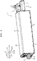
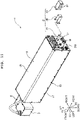
FIG. 3 is a perspective view showing the same laser marker without an outer cover. -
FIG. 4 is a schematic view for explaining a piping system for compressed air in the same laser marker. -
FIG. 5 is a view showing an enlarged part A ofFIG. 3 . -
FIG. 6 is another view showing the enlarged part A ofFIG. 3 . -
FIG. 7 is a front view showing the same laser marker without the outer cover. -
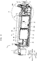
FIG. 8 is a plan view showing the same laser marker without the outer cover. -
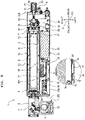
FIG. 9 is a view showing the cross section cut up along the line I-I ofFIG. 7 of the same laser marker without the outer cover. -
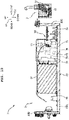
FIG. 10 is a view showing the cross section cut up along the line II-II ofFIG. 8 of the same laser marker without the outer cover. -
FIG. 11 is a perspective view showing the same laser marker with a silencer being disassembled. -
FIG. 12 is another perspective view showing the same laser marker with the silencer being disassembled. - Hereinbelow, an explanation will be made on a laser marker of the present disclosure, based on an embodiment having made the same in a concrete manner, referring to the accompanied drawings. In the drawings used for the following explanation, part of the basic configuration may be omitted in illustration, and the ratio in size and the like may not be necessarily correct for each illustrated part. In the respective drawings, a front/rear direction D1, an up/down direction D2 and a left/right direction D3 are presented as indicated in each drawing.
- As shown in
FIGs. 1 and2 , alaser marker 1 of this embodiment is dust-proof and water-proof, including afirst body 3, asecond body 5, and athird body 7. From thethird body 7, laser beam R is emitted for marking (printing) processing. The laser beam R is oscillated and emitted from alaser emission unit 9 provided inside thefirst body 3, reflected from a reflectingmirror 11 provided inside thesecond body 5, and finally scanned and collected by agalvanic scanner 13 and anfθ lens 15 provided inside the third body 7 (seeFIGs. 9 and10 ). - Inside the
first body 3, air cooling is performed by way of taking in compressed air from anair intake port 17, and discharging the air from anexhaust port 19 or asilencer 21. Note that theair intake port 17 is connected with an unshown air compressor provided separate from thelaser marker 1, via a pipe. The compressed air supplied from the air compressor is taken into thefirst body 3 from theair intake port 17. Theair intake port 17 and theexhaust port 19 are pipe joints of one-touch type. Thefirst body 3 is shaped into an approximate cuboid elongate in the front/rear direction D1, including abase member 23 and anouter cover 25. Thebase member 23 and theouter cover 25 are fixed withscrews 27. - In the
laser marker 1 of this embodiment, although many of its components (for example, theouter cover 25 and the like) are fixed with the screws in a removable manner, detailed explanation is omitted. Note that the screws for fixation are in a plurality of types. - Hereinbelow, referring to the drawings and the like showing the
first body 3 where theouter cover 25 is removed, thefirst body 3 will be explained. As shown inFIG. 3 , thebase member 23 includes abase plate 23A, aback plate 23B, and afront plate 23C. Theback plate 23B is provided to stand up from the rear end of thebase plate 23A. Theback plate 23B is provided with theair intake port 17, theexhaust port 19, thesilencer 21, and the like. Thefront plate 23C is provided to stand up from the front end of thebase plate 23A. Thefront plate 23C is provided with the second body 5 (and the third body 7). - On the
base plate 23A, thelaser emission unit 9 is arranged along the front/rear direction D1 and, on the left side of thelaser emission unit 9, agalvanic substrate 29, amain substrate 31, apower unit 33 and the like are arranged. Thegalvanic substrate 29 is a substrate for controlling thegalvanic scanner 13. Themain substrate 31 is a substrate for controlling thelaser marker 1 and is fixed on thebase plate 23A via ametallic bracket 32. Thebracket 32 is bent into an approximate L shape as viewed from the front/rear direction D1, and fixed with themain substrate 31 on the left surface at the other side than thelaser emission unit 9. Thepower unit 33 is provided to supply electric power to thelaser marker 1. - The
laser emission unit 9 is covered by aninner cover 35. Theinner cover 35 is shaped into an approximate cuboid elongate in the front/rear direction D1, and its lower side, front side and rear side are all open. When theinner cover 35 is fixed on thebase plate 23A along the front/rear direction D1, then a space is formed in theinner cover 35 to accommodate thelaser emission unit 9 therein and let the front side and the rear side be open. - Inside the
first body 3, aleft surface 35A of theinner cover 35 partitions the space into a first space S1 and a second space S2. That is, inside thefirst body 3, the first space S1 is the right part from theleft surface 35A of theinner cover 35 whereas the second space S2 is the left part from theleft surface 35A of theinner cover 35. Thelaser emission unit 9 and the like are arranged in the first space S1. Thegalvanic substrate 29, the main substrate 31 (and the bracket 32), thepower unit 33, and the like are arranged in the second space S2. By virtue of this, between thelaser emission unit 9 and the main substrate 31 (and the bracket 32), theleft surface 35A of theinner cover 35 is interposed. - The second space S2 is in communication with the first space S1 at both sides in the front/rear direction D1 in which the
left surface 35A of theinner cover 35 extends. Theback plate 23B, where theexhaust port 19 and thesilencer 21 are provided, is arranged at the rear side among the two sides in the front/rear direction D1 where the first space S1 and the second space S2 are in communication. On the other hand, thefront plate 23C is arranged at the front side among the two sides in the front/rear direction D1 where the first space S1 and the second space S2 are in communication. - A
pipe 37 shown inFIG. 4 is provided in thefirst body 3. Thepipe 37 is adapted to schematically show a system where the compressed air flows. The compressed air is taken into thefirst body 3 from theair intake port 17. The system of thepipe 37 will be explained below. Note that a specific configuration of thepipe 37 will be described later. Thepipe 37 is configured for the compressed air to flow therethrough and constructed from amain pipe 39, afirst branch pipe 41, asecond branch pipe 43, and athird branch pipe 45. One end of themain pipe 39 is connected to theair intake port 17. The other end of themain pipe 39 serves as afirst branch point 47. The internal diameter of themain pipe 39 is, for example, 5 mm. Themain pipe 39 is branched into thefirst branch pipe 41 and thesecond branch pipe 43 at thefirst branch point 47. - The internal diameter of the
first branch pipe 41 is, for example, 5 mm. Asecond branch point 49 is provided midway in thesecond branch pipe 43. Thesecond branch pipe 43 is branched into thethird branch pipe 45 and another part of thesecond branch pipe 43 at thesecond branch point 49. Thesecond branch pipe 43 has such an internal diameter of 5 mm, for example, as from thefirst branch point 47 to thesecond branch point 49, and such an internal diameter of 2.5 mm, for example, as from thesecond branch point 49 to aleading end 43A. The internal diameter of thethird branch pipe 45 is, for example, 5 mm. Aleading end 41A of thefirst branch pipe 41, theleading end 43A of thesecond branch pipe 43, and aleading end 45A of thethird branch pipe 45 are open from which the compressed air taken from theair intake port 17 is jetted. - A specific explanation will be made for such system of the
pipe 37. As shown inFIGs. 5 to 7 , to theair intake port 17, aconduit tube 51, anelectromagnetic valve 53, aconduit tube 55, and a first branch joint 57 are connected in the same order as written herein. Theelectromagnetic valve 53 is a so-called on/off valve. Thefirst branch joint 57 is a pipe joint of one-touch type branched in three directions. The pipe part from theair intake port 17 to the first branch joint 57 (therespective conduit tubes 51 and 55) correspond to themain pipe 39. That is, theelectromagnetic valve 53 is provided midway in themain pipe 39, and thefirst branch joint 57 is provided at thefirst branch point 47. The compressed air in themain pipe 39 is controlled by theelectromagnetic valve 53 for flowing and stop of the flowing. - A
conduit tube 59 and aleft nozzle 61 are connected to the first branch joint 57 in the same order as written herein. Theconduit tube 59 corresponds to thefirst branch pipe 41. That is, theleading end 41A of thefirst branch pipe 41 is provided with theleft nozzle 61. - Further, a
conduit tube 63, a second branch joint 65, and aconduit tube 67 are connected to the first branch joint 57 in the same order as written herein. The second branch joint 65 is a pipe joint of one-touch type branched in three directions. Each of theconduit tubes second branch pipe 43. That is, thesecond branch point 49 is provided with thesecond branch joint 65. - A
conduit tube 69 and aright nozzle 71 are connected to the second branch joint 65 in the same order as written herein. Theconduit tube 69 corresponds to thethird branch pipe 45. That is, theleading end 45A of thethird branch pipe 45 is provided with theright nozzle 71. - Henceforth, the
respective conduit tubes pipe 37. - The
left nozzle 61 and theright nozzle 71 are positioned at the rear side of thelaser emission unit 9 in the first space S1, being directed to thelaser emission unit 9. Thelaser emission unit 9 is shaped into an approximate cuboid elongate in the front/rear direction D1. Among the six surfaces of thelaser emission unit 9, the left surface and the right surface are provided with aleft heat sink 73 and aright heat sink 75, respectively. The heat sinks 73 and 75 each have a plurality of plate-like fins arranged along the front/rear direction D1. Each of the heat sinks 73 and 75 is arranged between theinner cover 35 and thelaser emission unit 9. Theleft nozzle 61 is directed to theleft heat sink 73 while theright nozzle 71 is directed to theright heat sink 75. - The
conduit tube 67 is arranged to pass above thepower unit 33 in the second space S2 at the left side of theleft surface 35A of theinner cover 35. Further, as shown inFIGs. 8 to 10 , theconduit tube 67 passes through as far as between theleft surface 35A of theinner cover 35 and thebracket 32. Thepipe joint 77 of one-touch type is connected to the leading end of theconduit tube 67. That is, the pipe joint 77 is connected to theleading end 43A of thesecond branch pipe 43. - The pipe joint 77 is fixed on a projecting
piece 78 projecting from thebracket 32 to the right side due to thebracket 32 being partially cut in up, in a state of being directed a little more to the left side than at the rear side (that is, to the side of the bracket 32). Between thebracket 32 and themain substrate 31, twothermal conducting sheets thermal conducting sheets bracket 32 and in tight contact with heat emitting elements comparatively weak in heat-resisting property among the electric parts mounted on themain substrate 31. By virtue of this, themain substrate 31 transmits its heat to themetallic bracket 32 via the respectivethermal conducting sheets piece 78 of thebracket 32, as described above, and is directed to the respectivethermal conducting sheets bracket 32, from the right side of thebracket 32 by way of being directed a little more to the left side than to the rear side (that is, to the side of the bracket 32). - Inside the
first body 3, the compressed air taken in from theair intake port 17 is jetted out from theleft nozzle 61, theright nozzle 71, and the pipe joint 77. The compressed air having jetted from theleft nozzle 61 and the pipe joint 77 flows frontward in the first space S1 between theinner cover 35 and thelaser emission unit 9 to hit thefront plate 23C and then flow rearward in the second space S2 after taking away the heat of thelaser emission unit 9 from therespective heat sinks - The compressed air having jetted from the pipe joint 77 hits the
bracket 32 in the second space S2 so as to flow rearward in the second space S2 after taking away the heat of themain substrate 31. - In this manner, the air having taken away the heat from the
laser emission unit 9 or themain substrate 31 flows rearward in the second space S2, and is then discharged out of thefirst body 3 from theexhaust port 19 or thesilencer 21 provided on theback plate 23B. - As shown in
FIGs. 9 ,11 and12 , thesilencer 21 includes asilencer body 81, afirst cover member 83, and asecond cover member 85. Thefirst cover member 83 is bent into a C-shape in a planar view, and its front side, upper side, and lower side are open. Thefirst cover member 83 is fixed on theback plate 23B to enclose thesilencer body 81 which passes through from the front side of thefirst cover member 83. Thesecond cover member 85 is shaped into an approximate cuboid, each of right surface and left surface thereof is formed with aslit 87, and its front side is open. Thesilencer body 81 and thefirst cover member 83 are set into thesecond cover member 85 from the front side, and thesecond cover member 85 is fixed on theback plate 23B to enclose thesilencer body 81 and thefirst cover member 83. - By virtue of this, the
silencer 21 prevents liquids such as water and the like from flowing into thefirst body 3 from thesilencer body 81. The air discharged from thesilencer body 81 passes above or below thefirst cover member 83 and through theslit 87 of thesecond cover member 85 to be discharged out of thefirst body 3. - As explained above in detail, in the
laser marker 1 of this embodiment, theleft nozzle 61 of theconduit tube 59 for jetting the compressed air (theleading end 41A of the first branch pipe 41) is arranged to face thelaser emission unit 9 while thepipe joint 77 of theconduit tube 67 for jetting the compressed air (theleading end 43A of the second branch pipe 43) is arranged to face thebracket 32 fixing themain substrate 31. Therefore, in thelaser marker 1 of this embodiment, with the wind of the compressed air directly hitting thelaser emission unit 9 and the bracket 32 (the main substrate 31), exhausting heat is performed by way of forced convection such that improvement of the cooling efficiency is facilitated for thelaser emission unit 9 and the bracket 32 (the main substrate 31). Note that much the same is true on theright nozzle 71 of theconduit tube 69 for jetting the compressed air (theleading end 45A of the third branch pipe 45). Further, in thelaser marker 1 of this embodiment, because the bracket 32 (the main substrate 31) is cooled with the wind of the compressed air directly hit thereupon, it is possible to sufficiently cool thelaser emission unit 9 without being affected by the heat emitted at themain substrate 31. - Further, in the
laser marker 1 of this embodiment, due to theleft surface 35A of theinner cover 35 interposed between thelaser emission unit 9 and the bracket 32 (the main substrate 31), thermal barrier is applied between thelaser emission unit 9 and the bracket 32 (the main substrate 31). Therefore, improvement of the cooling efficiency is further facilitated for thelaser emission unit 9 and the bracket 32 (the main substrate 31). - Further, in the
laser marker 1 of this embodiment, the first space S1 where thelaser emission unit 9 is arranged is in communication with the second space S2 where the bracket 32 (the main substrate 31) is arranged, on both sides in the front/rear direction D1 along which theleft surface 35A of theinner cover 35 extends. Further, in the first space S1, at the rear side of thelaser emission unit 9 in the front/rear direction D1, theleft nozzle 61 of the conduit tube 59 (theleading end 41A of the first branch pipe 41) is arranged. Further, theexhaust port 19 and thesilencer 21 are provided on theback plate 23B of thefirst body 3 positioned at the rear side in the front/rear direction D1. - Therefore, the compressed air having jetted from the
left nozzle 61 of the conduit tube 59 (theleading end 41A of the first branch pipe 41) flows frontward from the rear part in the first space S1 in the front/rear direction D1 and, further, flows rearward from the front part in the second space S2 in the front/rear direction D1 to be discharged out of thefirst body 3 from theexhaust port 19 or thesilencer 21. In this manner, in thelaser marker 1 of this embodiment, the air flowing circularly inside thefirst body 3 is discharged out of thefirst body 3 such that exhausting heat is performed efficiently by the forced convection. Note that much the same is true on theright nozzle 71 of the conduit tube 69 (theleading end 45A of the third branch pipe 45) for jetting the compressed air. - Further, in the
laser marker 1 of this embodiment, in the second space S2, thepipe joint 77 of the conduit tube 67 (theleading end 43A of the second branch pipe 43) is directed a little more to the left side than to the rear side (that is, to the side of the bracket 32) in the front/rear direction. Therefore, in the second space S2, because the compressed air having jetted from thepipe joint 77 of the conduit tube 67 (theleading end 43A of the second branch pipe 43) flows rearward from the front side in the front/rear direction D1, the compressed air having jetted from theleft nozzle 61 of the conduit tube 59 (theleading end 41A of the first branch pipe 41) flows in the same direction. By virtue of this, with thelaser marker 1 of this embodiment, it is possible to stabilize the air flow inside thefirst body 3. Nate that much the same is true on theright nozzle 71 of the conduit tube 69 (theleading end 45A of the third branch pipe 45) for jetting the compressed air. - Further, in the
laser marker 1 of this embodiment, theleft nozzle 61 of the conduit tube 59 (theleading end 41A of the first branch pipe 41) is directed to theleft heat sink 73 of thelaser emission unit 9 whereas theright nozzle 71 of the conduit tube 69 (theleading end 45A of the third branch pipe 45) is directed to theright heat sink 75 of thelaser emission unit 9. Therefore, in thelaser marker 1 of this embodiment, the compressed air having jetted from theleft nozzle 61 of the conduit tube 59 (theleading end 41A of the first branch pipe 41) flows toward theleft heat sink 73 of thelaser emission unit 9 whereas the compressed air having jetted from theright nozzle 71 of the conduit tube 69 (theleading end 45A of the third branch pipe 45) flows toward theright heat sink 75 of thelaser emission unit 9, such that heat dissipation is performed efficiently for thelaser emission unit 9. - Further, in the
laser marker 1 of this embodiment, thethermal conducting sheets main substrate 31 and thebracket 32. Further, thepipe joint 77 of the conduit tube 67 (theleading end 43A of the second branch pipe 43) is directed to the respectivethermal conducting sheets bracket 32, from the right side of thebracket 32. Therefore, if the compressed air has jetted from thepipe joint 77 of the conduit tube 67 (theleading end 43A of the second branch pipe 43), then the compressed air hits thebracket 32 such that it is possible for the compressed air to take away the heat transmitted from themain substrate 31 to thebracket 32 via the respectivethermal conducting sheets pipe joint 77 of the conduit tube 67 (theleading end 43A of the second branch pipe 43), because the heat is transmitted from themain substrate 31 to thebracket 32 via the respectivethermal conducting sheets main substrate 31 is still maintained. - Further, in the
laser marker 1 of this embodiment, the conduit tube 69 (the third branch pipe 45) has a larger internal diameter (for example, 5 mm) than the conduit tube 67 (for example, 2.5 mm; that is, the part of thesecond branch pipe 43 from theleading end 43A of thesecond branch pipe 43 to the second branch point 49). In other words, theconduit tube 67 has a smaller internal diameter (for example, 2.5 mm; that is, one part of thesecond branch pipe 43 including theleading end 43A of the second branch pipe 43) than the conduit tube 59 (thefirst branch pipe 41; for example, 5 mm). - In this manner, in the
laser marker 1 of this embodiment, by applying a difference in internal diameter to therespective conduit tubes left nozzle 61 of the conduit tube 59 (theleading end 41A of the first branch pipe 41), thepipe joint 77 of the conduit tube 67 (theleading end 43A of the second branch pipe 43), and theright nozzle 71 of the conduit tube 69 (theleading end 45A of the third branch pipe 45), is adjusted according to the heat emitting amount of thelaser emission unit 9 and the heat emitting amount of themain substrate 31. - In this embodiment, meanwhile, the
laser marker 1 is an example of the "laser processing device". The left surface and the right surface of thelaser emission unit 9 are examples of the "at least two lateral surfaces of the plurality of lateral surfaces constructing the laser emission unit". Theexhaust port 19 and thesilencer 21 are examples of the "vent". Thefirst body 3 is an example of the "casing". Theback plate 23B is an example of the "lateral surface positioned at the other side in the partitioning direction among the plurality of lateral surfaces constructing the casing". Themain substrate 31 and thebracket 32 are examples of the "control member". Thebracket 32 is an example of the "fixing member". Theleft surface 35A of theinner cover 35 is an example of the "wall". Thesecond branch point 49 is an example of the "branched position of the third branch pipe". Theleft heat sink 73 and theright heat sink 75 are examples of the "plurality of heat sinks". Theleft heat sink 73 is an example of the "one heat sink". Theright heat sink 75 is an example of the "other heat sink". Each of thethermal conducting sheets - Note that the present disclosure is not limited to this embodiment but can be changed in various manners without departing from the true spirit thereof. For example, even if either the
left nozzle 61 of the conduit tube 59 (theleading end 41A of the first branch pipe 41) or theright nozzle 71 of the conduit tube 69 (theleading end 45A of the third branch pipe 45) is omitted, improvement of the cooling efficiency is still facilitated for thelaser emission unit 9 and the bracket 32 (the main substrate 31). - Further, the
respective heat sinks laser emission unit 9 may each have a fin in a shape of needle-point holder or a bellows-like fin, for example, instead of the plurality of plate-like fins. Further, in thelaser emission unit 9, instead of theleft heat sink 73 or theright heat sink 75, an upper heat sink may be provided on the upper surface of thelaser emission unit 9. In such a case, theleft nozzle 61 of the conduit tube 59 (theleading end 41A of the first branch pipe 41) or theright nozzle 71 of the conduit tube 69 (theleading end 45A of the third branch pipe 45) is directed to the upper sink. - Further, if the
exhaust port 19 and thesilencer 21 are arranged on theback plate 23B at the side of the second space S2, that is, on the left part of theback plate 23B, then the first space S1 and the second space S2 may be in communication only on the front side in the front/rear direction D1 in which theleft surface 35A of theinner cover 35 extends. - Further, instead of the compressed air, a compressed gas such as nitrogen, helium or the like, for example, may be taken into the
air intake port 17. - 1: Laser marker, 3: First body, 9: Laser emission unit, 19: Exhaust port, 21: Silencer, 23B: Back plate, 31: Main substrate, 32: Bracket, 35A: Left surface of inner cover, 37: Pipe, 41: First branch pipe, 41A: Leading end of first branch pipe, 43: Second branch pipe, 43A: Leading end of second branch pipe, 45: Third branch pipe, 45A: Leading end of third branch pipe, 49: Second branch point, 59: Conduit tube, 61: Left nozzle, 63: Conduit tube, 65: Second branch joint, 67: Conduit tube, 69: Conduit tube, 71: Right nozzle, 73: Left heat sink, 75: Right heat sink, 77: Pipe joint, 79: Thermal conducting sheet, S1: First space, S2: Second space, D1: Front/rear direction, R: Laser beam
Claims (10)
- A laser processing device comprising:a laser emission unit configured to emit laser beam;a control member configured to control the laser emission unit;a casing in which the laser emission unit and the control member are accommodated; anda pipe through which compressed gas supplied from outside of the casing flows in a branched manner, the pipe being provided in the casing,wherein the pipe includes a first branch pipe arranged with a leading end for jetting the compressed gas facing the laser emission unit, and a second branch pipe arranged with a leading end for jetting the compressed gas facing the control member.
- The laser processing device according to claim 1, further comprising a wall provided between the laser emission unit and the control member.
- The laser processing device according to claim 2, further comprising:a first space which is a space formed by partitioning inside the casing by the wall and in which the laser emission unit is arranged; anda second space which is a space formed by partitioning inside the casing by the wall, in which the control member is arranged, and which is in communication with the first space at least on one side in a partitioning direction along which the wall extends,wherein the leading end of the first branch pipe is arranged on the other side in the partitioning direction with respect to the laser emission unit in the first space, anda vent for discharging the gas inside the casing to the outside of the casing is provided in a lateral surface, which is included in a plurality of lateral surfaces constructing the casing and which is positioned on the other side in the partitioning direction.
- The laser processing device according to claim 3, wherein in the second space, the leading end of the second branch pipe is directed to the other side in the partitioning direction.
- The laser processing device according to any one of claims 1 to 4, further comprising a third branch pipe arranged with a leading end for jetting the compressed gas facing the laser emission unit,wherein the laser emission unit comprises a plurality of heat sinks provided respectively on at least two lateral surfaces, which are included in a plurality of lateral surfaces constructing the laser emission unit,the leading end of the first branch pipe is directed to one heat sink among the plurality of heat sinks, andthe leading end of the third branch pipe is directed to another heat sink among the plurality of heat sinks.
- The laser processing device according to any one of claims 1 to 5,
wherein the control member comprises:a control substrate;a metallic fixing member which is fixed on the casing in a state that the control substrate is attached to the fixing member; anda thermal conducting member which is interposed between the control substrate and the fixing member, andthe leading end of the second branch pipe is directed to the thermal conducting member from a side of the fixing member. - The laser processing device according to claim 5, wherein the third branch pipe branches from the second branch pipe.
- The laser processing device according to claim 7, wherein the third branch pipe has an internal diameter larger than an internal diameter of a part, of the second branch pipe, which is defined from the leading end of the second branch pipe to a branching position of the third branch pipe.
- The laser processing device according to claim 7, wherein the first branch pipe has an internal diameter larger than an internal diameter of a part, of the second branch pipe, which is defined from the leading end of the second branch pipe to a branching position of the third branch pipe.
- The laser processing device according to any one of claims 1 to 9, wherein a part of the second branch pipe including the leading end of the second branch pipe has an internal diameter smaller than an internal diameter of the first branch diameter.
Applications Claiming Priority (2)
| Application Number | Priority Date | Filing Date | Title |
|---|---|---|---|
| JP2019175213A JP7279600B2 (en) | 2019-09-26 | 2019-09-26 | Laser processing equipment |
| PCT/JP2020/004510 WO2021059548A1 (en) | 2019-09-26 | 2020-02-06 | Laser processing device |
Publications (3)
| Publication Number | Publication Date |
|---|---|
| EP4035824A1 true EP4035824A1 (en) | 2022-08-03 |
| EP4035824A4 EP4035824A4 (en) | 2023-10-25 |
| EP4035824B1 EP4035824B1 (en) | 2025-01-08 |
Family
ID=75155234
Family Applications (1)
| Application Number | Title | Priority Date | Filing Date |
|---|---|---|---|
| EP20867168.5A Active EP4035824B1 (en) | 2019-09-26 | 2020-02-06 | Laser processing device |
Country Status (4)
| Country | Link |
|---|---|
| US (1) | US12665372B2 (en) |
| EP (1) | EP4035824B1 (en) |
| JP (1) | JP7279600B2 (en) |
| WO (1) | WO2021059548A1 (en) |
Families Citing this family (1)
| Publication number | Priority date | Publication date | Assignee | Title |
|---|---|---|---|---|
| WO2026120495A1 (en) * | 2024-12-05 | 2026-06-11 | Graf Synergy S.R.L. | Laser marker |
Family Cites Families (25)
| Publication number | Priority date | Publication date | Assignee | Title |
|---|---|---|---|---|
| JPS63172481A (en) * | 1987-01-10 | 1988-07-16 | Hitachi Ltd | Laser generator |
| US5253261A (en) * | 1992-04-21 | 1993-10-12 | American Laser Corporation | Gas laser solenoid and cooling apparatus |
| JPH08132235A (en) * | 1994-11-11 | 1996-05-28 | Fanuc Ltd | Cooling device for industrial welding robot |
| US5661746A (en) * | 1995-10-17 | 1997-08-26 | Universal Laser Syatems, Inc. | Free-space gas slab laser |
| US5748656A (en) | 1996-01-05 | 1998-05-05 | Cymer, Inc. | Laser having improved beam quality and reduced operating cost |
| JPH1022549A (en) | 1996-07-05 | 1998-01-23 | Nikon Corp | Laser optical device |
| US5790575A (en) * | 1996-07-15 | 1998-08-04 | Trw Inc. | Diode laser pumped solid state laser gain module |
| US6307871B1 (en) * | 1998-09-11 | 2001-10-23 | Cutting Edge Optronics, Inc. | Laser system using phase change material for thermal control |
| US6813289B2 (en) * | 2001-07-25 | 2004-11-02 | Innotech, Usa, Inc. | Portable laser device |
| US9987185B1 (en) * | 2002-02-27 | 2018-06-05 | CAMS Medical Instruments, Inc. | Transducer devices, apparatus, systems and methods of operation |
| JP4348958B2 (en) * | 2003-02-04 | 2009-10-21 | ブラザー工業株式会社 | Inkjet printer and maintenance method thereof |
| JP4199018B2 (en) * | 2003-02-14 | 2008-12-17 | 株式会社日立製作所 | Rack mount server system |
| US7136613B2 (en) * | 2003-03-10 | 2006-11-14 | Brother Kogyo Kabushiki Kaisha | Multicolor image forming apparatus and image making device |
| US7715454B2 (en) * | 2003-12-04 | 2010-05-11 | Universal Laser Systems, Inc. | Method and apparatus for cooling a laser |
| US7564888B2 (en) * | 2004-05-18 | 2009-07-21 | Cymer, Inc. | High power excimer laser with a pulse stretcher |
| US20090194260A1 (en) * | 2008-02-04 | 2009-08-06 | Chih-Peng Liao | Cooling apparatus for graphic cards |
| DE102012205870B3 (en) * | 2012-04-11 | 2013-02-21 | Trumpf Laser- Und Systemtechnik Gmbh | Cooling arrangement for cooling of laser gas for gas laser system, has secondary cooling circuit with supplementary heat exchanger that is located for additional cooling of laser gas flowing from fan to resonator |
| JP2013239696A (en) * | 2012-04-16 | 2013-11-28 | Amada Co Ltd | Fiber laser machining device, fiber laser oscillator, and dehumidifying method of fiber laser oscillator |
| JP6156311B2 (en) * | 2014-09-29 | 2017-07-05 | ブラザー工業株式会社 | Laser module, laser oscillator and laser processing apparatus |
| JP6435153B2 (en) * | 2014-10-14 | 2018-12-05 | 株式会社アマダホールディングス | Laser resonator, laser processing apparatus, and laser resonator dehumidification method |
| ES2576962B1 (en) | 2015-01-09 | 2017-01-23 | Macsa Id, S.A. | Equipment for laser marking of products |
| KR101821927B1 (en) * | 2017-07-19 | 2018-01-25 | 이영호 | Electronic money mining system |
| CN112448253A (en) * | 2019-08-30 | 2021-03-05 | 中国科学院大连化学物理研究所 | Solid laser gain module cooled by supersonic low-temperature gas and laser |
| CN113300194A (en) * | 2021-07-15 | 2021-08-24 | 武汉锐科光纤激光技术股份有限公司 | Self-circulation liquid cooling system and pulse laser |
| CN113690720B (en) * | 2021-08-17 | 2023-01-06 | 岗春智能装备制造(江苏)有限公司 | A laser head cooling device |
-
2019
- 2019-09-26 JP JP2019175213A patent/JP7279600B2/en active Active
-
2020
- 2020-02-06 EP EP20867168.5A patent/EP4035824B1/en active Active
- 2020-02-06 WO PCT/JP2020/004510 patent/WO2021059548A1/en not_active Ceased
-
2022
- 2022-03-24 US US17/702,931 patent/US12665372B2/en active Active
Also Published As
| Publication number | Publication date |
|---|---|
| US20220216663A1 (en) | 2022-07-07 |
| JP2021049563A (en) | 2021-04-01 |
| WO2021059548A1 (en) | 2021-04-01 |
| US12665372B2 (en) | 2026-06-23 |
| JP7279600B2 (en) | 2023-05-23 |
| EP4035824B1 (en) | 2025-01-08 |
| EP4035824A4 (en) | 2023-10-25 |
Similar Documents
| Publication | Publication Date | Title |
|---|---|---|
| US11693228B2 (en) | Device for heat dissipation from an endoscopic illumination apparatus | |
| EP4410686B1 (en) | Unmanned aerial vehicle base station and unmanned aerial vehicle system | |
| CN105492969B (en) | Light supply apparatus and image display device | |
| US20220216663A1 (en) | Laser processing apparatus | |
| US20070103647A1 (en) | Optical device and optical apparatus | |
| JP2016072338A (en) | Laser module, laser oscillator and laser processing apparatus | |
| EP2675025B1 (en) | Light source apparatus | |
| CN103775974B (en) | Light-focusing type lightguide and light supply apparatus | |
| JP2002148714A (en) | Display device | |
| CZ310301B6 (en) | A lighting device for a motor vehicle | |
| US11369259B2 (en) | Endoscopic device and heat radiator | |
| JP6396199B2 (en) | Laser processing equipment | |
| JP2005321525A (en) | projector | |
| CN220983707U (en) | Projector optical machine and projector | |
| JP6432160B2 (en) | Light source unit and light source device | |
| JP2020076849A (en) | Electronic apparatus and projector | |
| JP2019185021A (en) | Illumination device | |
| JP2022158264A (en) | X-ray inspection device | |
| CN222953524U (en) | Laser and laser device | |
| CN217848624U (en) | Laser beam combining device | |
| JP2000057840A (en) | Spot light source device | |
| CN222868316U (en) | Heat dissipation mechanism of laser | |
| JP2015222675A (en) | Cooling structure and light source unit | |
| JP2017156482A (en) | Image projection device | |
| CN223966809U (en) | Laser beam combining device and projection apparatus |
Legal Events
| Date | Code | Title | Description |
|---|---|---|---|
| STAA | Information on the status of an ep patent application or granted ep patent |
Free format text: STATUS: THE INTERNATIONAL PUBLICATION HAS BEEN MADE |
|
| PUAI | Public reference made under article 153(3) epc to a published international application that has entered the european phase |
Free format text: ORIGINAL CODE: 0009012 |
|
| STAA | Information on the status of an ep patent application or granted ep patent |
Free format text: STATUS: REQUEST FOR EXAMINATION WAS MADE |
|
| 17P | Request for examination filed |
Effective date: 20220315 |
|
| AK | Designated contracting states |
Kind code of ref document: A1 Designated state(s): AL AT BE BG CH CY CZ DE DK EE ES FI FR GB GR HR HU IE IS IT LI LT LU LV MC MK MT NL NO PL PT RO RS SE SI SK SM TR |
|
| DAV | Request for validation of the european patent (deleted) | ||
| DAX | Request for extension of the european patent (deleted) | ||
| P01 | Opt-out of the competence of the unified patent court (upc) registered |
Effective date: 20230529 |
|
| A4 | Supplementary search report drawn up and despatched |
Effective date: 20230927 |
|
| RIC1 | Information provided on ipc code assigned before grant |
Ipc: H01S 3/02 20060101ALI20230921BHEP Ipc: H01S 3/04 20060101ALI20230921BHEP Ipc: B23K 37/00 20060101ALI20230921BHEP Ipc: B23K 26/70 20140101AFI20230921BHEP |
|
| GRAP | Despatch of communication of intention to grant a patent |
Free format text: ORIGINAL CODE: EPIDOSNIGR1 |
|
| STAA | Information on the status of an ep patent application or granted ep patent |
Free format text: STATUS: GRANT OF PATENT IS INTENDED |
|
| RIC1 | Information provided on ipc code assigned before grant |
Ipc: H01S 3/02 20060101ALI20240807BHEP Ipc: H01S 3/04 20060101ALI20240807BHEP Ipc: B23K 37/00 20060101ALI20240807BHEP Ipc: B23K 26/70 20140101AFI20240807BHEP |
|
| INTG | Intention to grant announced |
Effective date: 20240909 |
|
| GRAS | Grant fee paid |
Free format text: ORIGINAL CODE: EPIDOSNIGR3 |
|
| GRAA | (expected) grant |
Free format text: ORIGINAL CODE: 0009210 |
|
| STAA | Information on the status of an ep patent application or granted ep patent |
Free format text: STATUS: THE PATENT HAS BEEN GRANTED |
|
| AK | Designated contracting states |
Kind code of ref document: B1 Designated state(s): AL AT BE BG CH CY CZ DE DK EE ES FI FR GB GR HR HU IE IS IT LI LT LU LV MC MK MT NL NO PL PT RO RS SE SI SK SM TR |
|
| REG | Reference to a national code |
Ref country code: GB Ref legal event code: FG4D |
|
| REG | Reference to a national code |
Ref country code: CH Ref legal event code: EP |
|
| REG | Reference to a national code |
Ref country code: DE Ref legal event code: R096 Ref document number: 602020044627 Country of ref document: DE |
|
| REG | Reference to a national code |
Ref country code: IE Ref legal event code: FG4D |
|
| REG | Reference to a national code |
Ref country code: LT Ref legal event code: MG9D |
|
| REG | Reference to a national code |
Ref country code: NL Ref legal event code: MP Effective date: 20250108 |
|
| REG | Reference to a national code |
Ref country code: AT Ref legal event code: MK05 Ref document number: 1758023 Country of ref document: AT Kind code of ref document: T Effective date: 20250108 |
|
| PG25 | Lapsed in a contracting state [announced via postgrant information from national office to epo] |
Ref country code: NL Free format text: LAPSE BECAUSE OF FAILURE TO SUBMIT A TRANSLATION OF THE DESCRIPTION OR TO PAY THE FEE WITHIN THE PRESCRIBED TIME-LIMIT Effective date: 20250108 |
|
| PG25 | Lapsed in a contracting state [announced via postgrant information from national office to epo] |
Ref country code: RS Free format text: LAPSE BECAUSE OF FAILURE TO SUBMIT A TRANSLATION OF THE DESCRIPTION OR TO PAY THE FEE WITHIN THE PRESCRIBED TIME-LIMIT Effective date: 20250408 |
|
| PG25 | Lapsed in a contracting state [announced via postgrant information from national office to epo] |
Ref country code: FI Free format text: LAPSE BECAUSE OF FAILURE TO SUBMIT A TRANSLATION OF THE DESCRIPTION OR TO PAY THE FEE WITHIN THE PRESCRIBED TIME-LIMIT Effective date: 20250108 |
|
| PG25 | Lapsed in a contracting state [announced via postgrant information from national office to epo] |
Ref country code: PL Free format text: LAPSE BECAUSE OF FAILURE TO SUBMIT A TRANSLATION OF THE DESCRIPTION OR TO PAY THE FEE WITHIN THE PRESCRIBED TIME-LIMIT Effective date: 20250108 |
|
| PG25 | Lapsed in a contracting state [announced via postgrant information from national office to epo] |
Ref country code: ES Free format text: LAPSE BECAUSE OF FAILURE TO SUBMIT A TRANSLATION OF THE DESCRIPTION OR TO PAY THE FEE WITHIN THE PRESCRIBED TIME-LIMIT Effective date: 20250108 |
|
| PG25 | Lapsed in a contracting state [announced via postgrant information from national office to epo] |
Ref country code: IS Free format text: LAPSE BECAUSE OF FAILURE TO SUBMIT A TRANSLATION OF THE DESCRIPTION OR TO PAY THE FEE WITHIN THE PRESCRIBED TIME-LIMIT Effective date: 20250508 Ref country code: NO Free format text: LAPSE BECAUSE OF FAILURE TO SUBMIT A TRANSLATION OF THE DESCRIPTION OR TO PAY THE FEE WITHIN THE PRESCRIBED TIME-LIMIT Effective date: 20250408 |
|
| PG25 | Lapsed in a contracting state [announced via postgrant information from national office to epo] |
Ref country code: HR Free format text: LAPSE BECAUSE OF FAILURE TO SUBMIT A TRANSLATION OF THE DESCRIPTION OR TO PAY THE FEE WITHIN THE PRESCRIBED TIME-LIMIT Effective date: 20250108 |
|
| PG25 | Lapsed in a contracting state [announced via postgrant information from national office to epo] |
Ref country code: LV Free format text: LAPSE BECAUSE OF FAILURE TO SUBMIT A TRANSLATION OF THE DESCRIPTION OR TO PAY THE FEE WITHIN THE PRESCRIBED TIME-LIMIT Effective date: 20250108 Ref country code: PT Free format text: LAPSE BECAUSE OF FAILURE TO SUBMIT A TRANSLATION OF THE DESCRIPTION OR TO PAY THE FEE WITHIN THE PRESCRIBED TIME-LIMIT Effective date: 20250508 |
|
| PG25 | Lapsed in a contracting state [announced via postgrant information from national office to epo] |
Ref country code: BG Free format text: LAPSE BECAUSE OF FAILURE TO SUBMIT A TRANSLATION OF THE DESCRIPTION OR TO PAY THE FEE WITHIN THE PRESCRIBED TIME-LIMIT Effective date: 20250108 Ref country code: GR Free format text: LAPSE BECAUSE OF FAILURE TO SUBMIT A TRANSLATION OF THE DESCRIPTION OR TO PAY THE FEE WITHIN THE PRESCRIBED TIME-LIMIT Effective date: 20250409 |
|
| PG25 | Lapsed in a contracting state [announced via postgrant information from national office to epo] |
Ref country code: AT Free format text: LAPSE BECAUSE OF FAILURE TO SUBMIT A TRANSLATION OF THE DESCRIPTION OR TO PAY THE FEE WITHIN THE PRESCRIBED TIME-LIMIT Effective date: 20250108 |
|
| PG25 | Lapsed in a contracting state [announced via postgrant information from national office to epo] |
Ref country code: SE Free format text: LAPSE BECAUSE OF FAILURE TO SUBMIT A TRANSLATION OF THE DESCRIPTION OR TO PAY THE FEE WITHIN THE PRESCRIBED TIME-LIMIT Effective date: 20250108 |
|
| REG | Reference to a national code |
Ref country code: CH Ref legal event code: PL |
|
| PG25 | Lapsed in a contracting state [announced via postgrant information from national office to epo] |
Ref country code: SM Free format text: LAPSE BECAUSE OF FAILURE TO SUBMIT A TRANSLATION OF THE DESCRIPTION OR TO PAY THE FEE WITHIN THE PRESCRIBED TIME-LIMIT Effective date: 20250108 |
|
| REG | Reference to a national code |
Ref country code: DE Ref legal event code: R097 Ref document number: 602020044627 Country of ref document: DE |
|
| PG25 | Lapsed in a contracting state [announced via postgrant information from national office to epo] |
Ref country code: DK Free format text: LAPSE BECAUSE OF FAILURE TO SUBMIT A TRANSLATION OF THE DESCRIPTION OR TO PAY THE FEE WITHIN THE PRESCRIBED TIME-LIMIT Effective date: 20250108 |
|
| PG25 | Lapsed in a contracting state [announced via postgrant information from national office to epo] |
Ref country code: MC Free format text: LAPSE BECAUSE OF FAILURE TO SUBMIT A TRANSLATION OF THE DESCRIPTION OR TO PAY THE FEE WITHIN THE PRESCRIBED TIME-LIMIT Effective date: 20250108 |
|
| PG25 | Lapsed in a contracting state [announced via postgrant information from national office to epo] |
Ref country code: LU Free format text: LAPSE BECAUSE OF NON-PAYMENT OF DUE FEES Effective date: 20250206 |
|
| PG25 | Lapsed in a contracting state [announced via postgrant information from national office to epo] |
Ref country code: CH Free format text: LAPSE BECAUSE OF NON-PAYMENT OF DUE FEES Effective date: 20250228 |
|
| PG25 | Lapsed in a contracting state [announced via postgrant information from national office to epo] |
Ref country code: EE Free format text: LAPSE BECAUSE OF FAILURE TO SUBMIT A TRANSLATION OF THE DESCRIPTION OR TO PAY THE FEE WITHIN THE PRESCRIBED TIME-LIMIT Effective date: 20250108 Ref country code: CZ Free format text: LAPSE BECAUSE OF FAILURE TO SUBMIT A TRANSLATION OF THE DESCRIPTION OR TO PAY THE FEE WITHIN THE PRESCRIBED TIME-LIMIT Effective date: 20250108 |
|
| PG25 | Lapsed in a contracting state [announced via postgrant information from national office to epo] |
Ref country code: RO Free format text: LAPSE BECAUSE OF FAILURE TO SUBMIT A TRANSLATION OF THE DESCRIPTION OR TO PAY THE FEE WITHIN THE PRESCRIBED TIME-LIMIT Effective date: 20250108 |
|
| PG25 | Lapsed in a contracting state [announced via postgrant information from national office to epo] |
Ref country code: SK Free format text: LAPSE BECAUSE OF FAILURE TO SUBMIT A TRANSLATION OF THE DESCRIPTION OR TO PAY THE FEE WITHIN THE PRESCRIBED TIME-LIMIT Effective date: 20250108 |
|
| PLBE | No opposition filed within time limit |
Free format text: ORIGINAL CODE: 0009261 |
|
| STAA | Information on the status of an ep patent application or granted ep patent |
Free format text: STATUS: NO OPPOSITION FILED WITHIN TIME LIMIT |
|
| REG | Reference to a national code |
Ref country code: BE Ref legal event code: MM Effective date: 20250228 |
|
| 26N | No opposition filed |
Effective date: 20251009 |
|
| PG25 | Lapsed in a contracting state [announced via postgrant information from national office to epo] |
Ref country code: BE Free format text: LAPSE BECAUSE OF NON-PAYMENT OF DUE FEES Effective date: 20250228 |
|
| PG25 | Lapsed in a contracting state [announced via postgrant information from national office to epo] |
Ref country code: IE Free format text: LAPSE BECAUSE OF NON-PAYMENT OF DUE FEES Effective date: 20250206 |
|
| PG25 | Lapsed in a contracting state [announced via postgrant information from national office to epo] |
Ref country code: IT Free format text: LAPSE BECAUSE OF FAILURE TO SUBMIT A TRANSLATION OF THE DESCRIPTION OR TO PAY THE FEE WITHIN THE PRESCRIBED TIME-LIMIT Effective date: 20250108 |
|
| PGFP | Annual fee paid to national office [announced via postgrant information from national office to epo] |
Ref country code: GB Payment date: 20260211 Year of fee payment: 7 |
|
| PGFP | Annual fee paid to national office [announced via postgrant information from national office to epo] |
Ref country code: DE Payment date: 20260213 Year of fee payment: 7 |
|
| PGFP | Annual fee paid to national office [announced via postgrant information from national office to epo] |
Ref country code: FR Payment date: 20260209 Year of fee payment: 7 |
|
| PG25 | Lapsed in a contracting state [announced via postgrant information from national office to epo] |
Ref country code: CY Free format text: LAPSE BECAUSE OF FAILURE TO SUBMIT A TRANSLATION OF THE DESCRIPTION OR TO PAY THE FEE WITHIN THE PRESCRIBED TIME-LIMIT Effective date: 20250108 |
|
| PG25 | Lapsed in a contracting state [announced via postgrant information from national office to epo] |
Ref country code: TR Free format text: LAPSE BECAUSE OF FAILURE TO SUBMIT A TRANSLATION OF THE DESCRIPTION OR TO PAY THE FEE WITHIN THE PRESCRIBED TIME-LIMIT Effective date: 20250108 |
|
| PG25 | Lapsed in a contracting state [announced via postgrant information from national office to epo] |
Ref country code: LT Free format text: LAPSE BECAUSE OF FAILURE TO SUBMIT A TRANSLATION OF THE DESCRIPTION OR TO PAY THE FEE WITHIN THE PRESCRIBED TIME-LIMIT Effective date: 20250108 |