EP4035784B1 - Underwater cleaning device for marine life on sealing surface of gate, and device combination and cleaning method - Google Patents
Underwater cleaning device for marine life on sealing surface of gate, and device combination and cleaning method Download PDFInfo
- Publication number
- EP4035784B1 EP4035784B1 EP20892652.7A EP20892652A EP4035784B1 EP 4035784 B1 EP4035784 B1 EP 4035784B1 EP 20892652 A EP20892652 A EP 20892652A EP 4035784 B1 EP4035784 B1 EP 4035784B1
- Authority
- EP
- European Patent Office
- Prior art keywords
- nozzle
- cleaning
- gate
- sealing surfaces
- underwater
- Prior art date
- Legal status (The legal status is an assumption and is not a legal conclusion. Google has not performed a legal analysis and makes no representation as to the accuracy of the status listed.)
- Active
Links
Images



Classifications
-
- B—PERFORMING OPERATIONS; TRANSPORTING
- B08—CLEANING
- B08B—CLEANING IN GENERAL; PREVENTION OF FOULING IN GENERAL
- B08B3/00—Cleaning by methods involving the use or presence of liquid or steam
- B08B3/02—Cleaning by the force of jets or sprays
-
- B—PERFORMING OPERATIONS; TRANSPORTING
- B08—CLEANING
- B08B—CLEANING IN GENERAL; PREVENTION OF FOULING IN GENERAL
- B08B3/00—Cleaning by methods involving the use or presence of liquid or steam
- B08B3/02—Cleaning by the force of jets or sprays
- B08B3/024—Cleaning by means of spray elements moving over the surface to be cleaned
-
- B—PERFORMING OPERATIONS; TRANSPORTING
- B08—CLEANING
- B08B—CLEANING IN GENERAL; PREVENTION OF FOULING IN GENERAL
- B08B13/00—Accessories or details of general applicability for machines or apparatus for cleaning
-
- B—PERFORMING OPERATIONS; TRANSPORTING
- B66—HOISTING; LIFTING; HAULING
- B66C—CRANES; LOAD-ENGAGING ELEMENTS OR DEVICES FOR CRANES, CAPSTANS, WINCHES, OR TACKLES
- B66C1/00—Load-engaging elements or devices attached to lifting or lowering gear of cranes or adapted for connection therewith for transmitting lifting forces to articles or groups of articles
- B66C1/10—Load-engaging elements or devices attached to lifting or lowering gear of cranes or adapted for connection therewith for transmitting lifting forces to articles or groups of articles by mechanical means
- B66C1/12—Slings comprising chains, wires, ropes, or bands; Nets
-
- B—PERFORMING OPERATIONS; TRANSPORTING
- B66—HOISTING; LIFTING; HAULING
- B66C—CRANES; LOAD-ENGAGING ELEMENTS OR DEVICES FOR CRANES, CAPSTANS, WINCHES, OR TACKLES
- B66C1/00—Load-engaging elements or devices attached to lifting or lowering gear of cranes or adapted for connection therewith for transmitting lifting forces to articles or groups of articles
- B66C1/10—Load-engaging elements or devices attached to lifting or lowering gear of cranes or adapted for connection therewith for transmitting lifting forces to articles or groups of articles by mechanical means
- B66C1/12—Slings comprising chains, wires, ropes, or bands; Nets
- B66C1/16—Slings with load-engaging platforms or frameworks
-
- B—PERFORMING OPERATIONS; TRANSPORTING
- B66—HOISTING; LIFTING; HAULING
- B66C—CRANES; LOAD-ENGAGING ELEMENTS OR DEVICES FOR CRANES, CAPSTANS, WINCHES, OR TACKLES
- B66C1/00—Load-engaging elements or devices attached to lifting or lowering gear of cranes or adapted for connection therewith for transmitting lifting forces to articles or groups of articles
- B66C1/10—Load-engaging elements or devices attached to lifting or lowering gear of cranes or adapted for connection therewith for transmitting lifting forces to articles or groups of articles by mechanical means
- B66C1/62—Load-engaging elements or devices attached to lifting or lowering gear of cranes or adapted for connection therewith for transmitting lifting forces to articles or groups of articles by mechanical means comprising article-engaging members of a shape complementary to that of the articles to be handled
- B66C1/66—Load-engaging elements or devices attached to lifting or lowering gear of cranes or adapted for connection therewith for transmitting lifting forces to articles or groups of articles by mechanical means comprising article-engaging members of a shape complementary to that of the articles to be handled for engaging holes, recesses, or abutments on articles specially provided for facilitating handling thereof
-
- E—FIXED CONSTRUCTIONS
- E02—HYDRAULIC ENGINEERING; FOUNDATIONS; SOIL SHIFTING
- E02B—HYDRAULIC ENGINEERING
- E02B8/00—Details of barrages or weirs ; Energy dissipating devices carried by lock or dry-dock gates
-
- B—PERFORMING OPERATIONS; TRANSPORTING
- B08—CLEANING
- B08B—CLEANING IN GENERAL; PREVENTION OF FOULING IN GENERAL
- B08B2203/00—Details of cleaning machines or methods involving the use or presence of liquid or steam
- B08B2203/02—Details of machines or methods for cleaning by the force of jets or sprays
- B08B2203/0288—Ultra or megasonic jets
-
- B—PERFORMING OPERATIONS; TRANSPORTING
- B63—SHIPS OR OTHER WATERBORNE VESSELS; RELATED EQUIPMENT
- B63B—SHIPS OR OTHER WATERBORNE VESSELS; EQUIPMENT FOR SHIPPING
- B63B59/00—Hull protection specially adapted for vessels; Cleaning devices specially adapted for vessels
- B63B59/06—Cleaning devices for hulls
- B63B59/08—Cleaning devices for hulls of underwater surfaces while afloat
- B63B2059/087—Cleaning devices for hulls of underwater surfaces while afloat the devices being adapted for being pulled across, or along the underwater surface to be cleaned, e.g. by ropes
-
- E—FIXED CONSTRUCTIONS
- E02—HYDRAULIC ENGINEERING; FOUNDATIONS; SOIL SHIFTING
- E02B—HYDRAULIC ENGINEERING
- E02B7/00—Barrages or weirs; Layout, construction, methods of, or devices for, making same
- E02B7/20—Movable barrages; Lock or dry-dock gates
- E02B7/54—Sealings for gates
Definitions
- the invention relates to the technical field of marine life cleaning, in particular to an underwater cleaning device for marine life on a sealing surface of a gate, a device combination and a cleaning method thereof.
- Chinese application CN106269623 A discloses an automatic cleaning machine including a frame, a longitudinal cleaning system, a transverse cleaning system, and a control system, to clean the sluice gate.
- the operation stability of the machine is to be improved.
- An aspect of the invention is to provide an underwater cleaning device for marine life on sealing surfaces of a gate, which has neither the inefficiency of the traditional cleaning method by divers nor the problems of poor movement stability of the cleaning device.
- Another aspect of the invention is to provide an underwater cleaning device combination for marine life on sealing surfaces of a gate, which has neither the inefficiency of the traditional cleaning method by divers nor the problems of poor movement stability of the cleaning device.
- Still an aspect of the invention is to provide an underwater cleaning method for marine life on sealing surfaces of a gate, which has neither the inefficiency of the traditional cleaning method by divers nor the problems of poor movement stability of the cleaning device.
- the present invention provides an underwater cleaning device for marine life on sealing surfaces of a gate, adapted for cleaning marine life attached to sealing surfaces of a gate of a building structure, the underwater cleaning device including a main structure, a cleaning structure installed on the main structure, and a rigging structure fixed to the main structure.
- the rigging structure is connected with a lifting device to drive the cleaning structure to move to a corresponding position on the sealing surfaces of the gate, and the cleaning structure is configured to clean the marine life on the sealing surfaces of the gate when the cleaning structure moves to the corresponding position on the sealing surfaces of the gate.
- the main structure comprises a truss arranged laterally and a moving carrier slidably provided on the truss
- the cleaning structure comprises a nozzle structure, a delivery pipe and a reel device
- the delivery pipe is configured to provide jetting fluid to the nozzle structure
- the nozzle structure comprises a first nozzle for cleaning an upper sealing surface of the sealing surfaces and a second nozzle for cleaning a lower sealing surface of the sealing surfaces
- the first nozzle and the second nozzle are mounted on the moving carrier.
- the reel device is mounted on the truss and configured to release or rewind the delivery pipe with a movement of the moving carrier, and the reel device comprises a reel body, a left guide wheel and a right guide wheel, the delivery pipe is wound on the reel body and is located between the left guide wheel and the right guide wheel.
- opposite sides of the main structure are respectively provided with a guide member for slidably matching with a guide rail that is extended in a vertical direction and provided on both sides of the sealing surfaces of the gate.
- the nozzle structure is configured to jet fluid in a direction angled at 30-40 degrees relative to the sealing surfaces of the gate.
- the nozzle structure is a cavitation nozzle structure.
- the nozzle structure further includes a third nozzle and a fourth nozzle respectively for cleaning a left sealing surface and a right sealing surface of the sealing surfaces, and the third nozzle and the fourth nozzle are mounted on left and right sides of the moving carrier respectively.
- the cleaning structure further includes a first valve for controlling fluid discharge of the first nozzle, a second valve for controlling fluid discharge of the second nozzle, and a third valve for control fluid discharge of the third nozzle and the fourth nozzle.
- the device further includes a vision system
- the vision system includes a camera device for collecting underwater image information and at least two fill light devices for providing light sources to the camera device, the fill light devices are respectively installed on left and right sides of the truss;
- the camera device includes a panoramic camera installed in a middle of the truss, a left camera and a right camera installed on the left and right sides of the truss, and a moving camera installed on the moving carrier.
- the rigging structure includes a lifting ring for connecting with the lifting device, a plurality of lifting ropes connected with the lifting ring, and a draw rod connected to a lower end of the lifting rope, the draw rod is connected with the main structure and has an adjustable length.
- the present invention further provides an underwater cleaning device combination for marine life on sealing surfaces of a gate, adapted for cleaning marine life attached to sealing surfaces of a gate of a building structure, the underwater cleaning device combination including an underwater cleaning device for marine life on sealing surfaces of a gate according to the invention and two guide rails, the guide rails being installed side by side on both sides of the sealing surfaces of the gate.
- the opposite sides of the main structure are respectively provided with a guide member for matching with the guide rails.
- a new marine life cleaning device is provided in the present invention, the main structure is fixed with the rigging structure, the cleaning structure is installed on the main structure, and the rigging structure is connected to the lifting device.
- the underwater cleaning device can be driven by the lifting device to move along the building structure to the position corresponding to the sealing surfaces of the gate, and then clean the marine life on the sealing surfaces by means of the cleaning structure, which has neither the inefficiency of the traditional cleaning method by divers nor the problems of poor movement stability of the cleaning device, and is applicable to the cleaning of marine life on the sealing surfaces of large gates.
- the cleaning device of the present invention is applicable to sealing surfaces of different gates with various sizes and various materials, without any material restriction of the building structure, to obtain good applicability. Furthermore, there is no need to move the main structure on the cleaning structure, which is applicable to perform cleanup on sharp edges and corners, and multiple planes.
- the present invention further provides an underwater cleaning method for marine life on sealing surfaces of a gate, adapted for cleaning marine life attached to sealing surfaces of a gate of a building structure.
- the method includes the following steps:
- the main structure comprises a truss arranged laterally and a moving carrier slidably provided on the truss
- the cleaning structure comprises a nozzle structure, a delivery pipe and a reel device
- the delivery pipe is configured to provide jetting fluid to the nozzle structure
- the nozzle structure comprises a first nozzle for cleaning an upper sealing surface of the sealing surfaces and a second nozzle for cleaning a lower sealing surface of the sealing surfaces
- the first nozzle and the second nozzle are mounted on the moving carrier.
- the reel device is mounted on the truss and configured to release or rewind the delivery pipe with a movement of the moving carrier, and the reel device comprises a reel body, a left guide wheel and a right guide wheel, the delivery pipe is wound on the reel body and is located between the left guide wheel and the right guide wheel.
- a new marine life cleaning method is provided in the present invention, the rigging structure of the underwater cleaning device is connected to a lifting device, and the underwater cleaning device is driven by the lifting device to move along the building structure to a position corresponding to the sealing surfaces of the gate, to clean the marine life on the sealing surfaces of the gate through the cleaning structure.
- the cleaning device of the present invention is applicable to sealing surfaces of different gates with various sizes and various materials, without any material restriction of the building structure, to obtain good applicability. Furthermore, there is no need to move the main structure on the cleaning structure, which is applicable to perform cleanup on sharp edges and corners, and multiple planes.
- the present disclosure provides an underwater cleaning device 100 for marine life on a sealing surface of a gate, which is adapted for connecting with a lifting device (not shown) and is movable in a vertical direction along a building structure 200 under the action of the lifting device, to clean up the marine life adhering to the sealing surface of the gate of the building structure 200.
- the device 100 includes a main structure 1, a cleaning structure installed on the main structure 1, and a rigging structure 3 fixed to the main structure 1.
- the rigging structure 3 is configured to connect with the lifting device to drive the main structure 1 with the cleaning structure supported to move along the building structure 200 to a corresponding position on the sealing surface of the gate, and the cleaning structure is configured to clean the marine life on the sealing surface of the gate when the cleaning structure moves to the corresponding position on the sealing surface of the gate.
- the opposite sides of the main structure 1 are respectively provided with a guide member 13 for slidably matching with a guide rail (not shown) that is extended in a vertical direction and provided on both sides of the sealing surface of the gate.
- a guide rail (not shown) that is extended in a vertical direction and provided on both sides of the sealing surface of the gate.
- the guide member 13 can move in the vertical direction along the guide rail, so that the underwater cleaning device 100 can stably move in the vertical direction along the building structure 200, without jamming due to the marine life bred on the guide rails.
- the guide member 13 is a guide wheel, which is not limited however.
- the lateral dimension of the main structure 1 is adapted to those of the building structure 200 and the guide rail, so as to ensure that the underwater cleaning device 100 can operate in a limited space, and transfer a reaction force generated during the cleaning to the guide rails and the building structure 200.
- the guides 13 are sized to match the guide rails, which is beneficial to transfer the reaction force generated during the cleaning to the guide rails.
- the lateral dimension of the main structure 1 can be adjusted adaptively according to the lateral dimension of the sealing surface of the gate to be cleaned, so that the underwater cleaning device 100 can be suitable for cleaning different sealing surfaces of various lateral dimensions, especially for the sealing surfaces of large vertical gantry gates.
- the rigging structure 3 includes a lifting ring 31 for connecting with the lifting device, a plurality of lifting ropes 32 connected with the lifting ring 31, and a draw rod 33 connected to a lower end of the lifting rope 32, the draw rod 33 is connected with the main structure 1, and has an adjustable length. By adjusting the length of the draw rod 33, the force balance of the rigging structure 3 is ensured, so that the underwater cleaning device 100 can move stably along the guide rails under the action of the lifting device. More specifically, the lifting rope 32 is a stainless steel wire rope, and the draw rod 33 is a basket draw rod.
- the cleaning structure includes a nozzle structure (not shown) and a delivery pipe (not shown) configured to provide jetting fluid to the nozzle structure.
- the nozzle structure is a cavitation nozzle structure, which uses strong force of micro-jet and shock waves generated by cavitation jet technology to remove the marine life.
- Such a structure is simple, which is suitable to effectively remove large-area marine life on the sealing surfaces of the gate.
- the sealing surfaces of the gate includes an upper sealing surface 210 matching with the lintel of the gate, a lower sealing surface 220 matching with the bottom of the gate, and a left sealing surface and a right sealing surface located on opposite sides of the upper sealing surface 210 and the lower sealing surface 220 (the four surfaces are formed like a door frame structure). Since the upper sealing surface 210 (vertical surface), the lower sealing surface 220 (horizontal surface), the left sealing surface (vertical surface) and the right sealing surface (vertical surface) are located in different planes, in this embodiment, different nozzles with different spray directions are applied to clean the four sealing surfaces, so that everywhere of the sealing surfaces of the gate may be cleaned without dead corners, thereby ensuring the cleaning effect of the sealing surfaces of the gate.
- the first nozzle 21 is configured to jet fluid in a direction angled at 30-40 degrees relative to the upper sealing surface 210
- the second nozzle 22 is configured to jet fluid in a direction angled at 30-40 degrees relative to the lower sealing surface 220
- the third nozzle 23 is configured to jet fluid in a direction angled at 30-40 degrees relative to the left sealing surface
- the fourth nozzle 24 is configured to jet fluid in a direction angled at 30-40 degrees relative to the right sealing surface, so as to optimized the cleaning effect.
- the main structure 1 includes a truss 11 arranged laterally and a moving carrier 12 slidably arranged on the truss 11.
- the first nozzle 21 and the second nozzle 22 are installed on the moving carrier 12.
- the main body structure 1 is driven by an external lifting device to reach the upper sealing surface 210 or the lower sealing surface 220, the first nozzle 21 and the second nozzle 22 carried by the moving carrier 12 to move laterally along the truss 11, so that the upper sealing surface 210 and the lower sealing surface 220 can be cleaned fully, to ensure the cleaning effect.
- the truss 11 includes a truss beam 111, a left end beam 112 installed on the left side of the truss beam 111, and a right end beam 113 installed on the right side of the truss beam 111.
- the third nozzle 23 is installed on the left end beam 112, and the fourth nozzle 24 is installed on the right end beam 113, when the underwater cleaning device 100 moves in the vertical direction along the guide rail under the action of the lifting device, the third nozzle 23 and the fourth nozzle 24 clean marine life on the left sealing surface and the left sealing surface respectively.
- the moving carrier 12 will simultaneously drive the first nozzle 21 and the second nozzle 22 to move laterally along the truss 11 when moving laterally along the truss 11.
- the moving carrier 12 may also include a plurality of independent moving parts that can move laterally along the truss 11, and the first nozzle 21 and the second nozzle 22 are independently installed on different moving parts, in such an arrangement, the first nozzle 21 and the second nozzle 22 can be driven by the moving parts respectively, so as to move laterally along the truss 11.
- the moving carrier 12 includes a main body 121, a wheel 122 mounted on the main body 121, a driving assembly 123, a lateral limiting wheel 124 and a vertical limiting wheel 125.
- the main body 121 is a welded structure, which is connected to the first nozzle 21 and the second nozzle 22 by bolts.
- the wheel 122 is connected to the output end of the drive assembly 123 and driven to move laterally along the truss beam 111.
- the drive assembly 123 dynamic and static technology is adopted, a motor is wrapped in the sealed cavity, and at the same time, compressed air is input into the sealed cavity, so that the sealed cavity maintains a slight positive pressure relative to the external environment.
- the motor in the driving assembly 123 is ensured to be worked normally in an environment with a water depth of 15 meters, to drive the wheels 122 normally.
- the lateral limiting wheel 124 is configured to realize the lateral limit of the wheel 122
- the vertical limit wheel 125 is configured to realize the vertical limit of the wheel 122.
- moving carrier, 12 is engaged with the truss beam 111 by gear rack, which is not limited thereto.
- the cleaning structure further includes a first valve 25 and a second valve 26 installed on the moving carrier 12, and a third valve 27 installed on the truss 11.
- the first valve 25 is configured to control the liquid outlet of the first nozzle 21
- the second valve 26 is configured to control the fluid discharge of the second nozzle 22
- the third valve 27 is configured to control the fluid discharge of the third nozzle 23 and the fourth nozzle 24. That is to say, the first nozzle 21 and the second nozzle 22 are separately controlled by the first valve 25 and the second valve 26, and the third nozzle 23 and the fourth nozzle 24 are simultaneously controlled by the third valve 27, which is convenient for cleaning the left and the right sealing surfaces.
- the first valve 25, the second valve 26 and the third valve 27 are all electromagnetic valves, which is not limited thereto however.
- the cleaning structure further includes a reel device 28 mounted on the truss beam 111, and the reel device 28 is configured to release or rewind the delivery pipe with the movement of the moving carrier 12.
- the reel device 28 uses a spring drive mechanism to realize the retraction of the delivery pipe.
- the reel device 28 includes a reel body 281, a left guide wheel 282 and a right guide wheel 283.
- the delivery pipe is wound on the reel body 281 and is located between the left guide wheel 282 and the right guide wheel 283.
- a desired delivery pipe can be ensured due to the reel body 281, and the delivery pipe can be bent to the left or right with a proper bending radius by means of the left guide wheel 282 and the right guide wheel 283, and further the delivery pipe will not interfere with the main structure 1.
- the underwater cleaning device 100 further includes a vision system having a camera device and a fill light device 45 for providing a light source to the camera device.
- the camera device includes a panoramic camera 41 mounted on the middle position of the truss beam 111, a left camera 42 mounted on the left end beam 112, a right camera 43 mounted on the right end beam 113, and a moving camera 44 mounted on the moving carrier 12.
- the moving camera 44 is configured to move laterally on the truss beam 111 with the moving carrier 12, collect underwater image information by each camera 41, 42, 43, 44, and transmit such information to an onshore monitor (not shown) through network cables, so that the operator can judge the underwater position of the underwater cleaning device 100, observe the marine life on the sealing surfaces of the gate, and check the jet state of the underwater cleaning device 100.
- Two fill light devices 45 is provided on the left end beam 112 and the right end beam 113 respectively, so as to establish a full coverage light field, thereby realizing all-round high-definition monitoring of each sealing surface of the gate.
- the two fill light devices 45 may also be installed at other positions of the truss 11, and the left camera 42 and the right camera 43 are not limited to be installed on the left end beam 112 and the right end beam 113.
- the present invention also provides an underwater cleaning device combination for marine life on the sealing surfaces of the gate, which is adapted for cleaning the marine life attached to the sealing surfaces of the gate of the building structure 200.
- the device combination includes the underwater cleaning device 100 according to the invention and two guide rails installed side by side on both sides of the sealing surfaces of the gate.
- the underwater cleaning device 100 includes a main structure 1, a cleaning structure installed on the main structure 1 for cleaning marine life, and a rigging structure fixed to the main structure 1.
- Two guide members 13 are arranged at opposite sides of the main structure 1 for matching with the guide rails.
- the rigging structure 3 is configured to connect with a lifting device to drive the cleaning structure to move to a corresponding position on the sealing surfaces of the gate, and the cleaning structure 1 is configured to clean the marine life on the sealing surfaces when the cleaning structure moves to the corresponding position on the sealing surfaces of the gate.
- the structures of the underwater cleaning device 100 are as described above, and are not repeated here.
- the lifting ring 31 of the underwater cleaning device 100 is hung on the hook of the lifting device, so that the underwater cleaning device 100 is lifted and transferred above (on the water) the gate of the building structure 200 to be cleaned.
- the structural integrity of the underwater cleaning device 100 is checked, after that, the underwater cleaning device 100 is lowered into the water at a low speed, and the vision system is turned on to monitor the underwater image information; sequentially, the underwater cleaning device 100 is continued to be lowered at a low speed to reach the bottom of the gate, during such a process, the growth of marine life on the sealing surfaces of the gate may be observed by the visual system.
- the underwater cleaning device 100 is lifted to the upper sealing surface 210 and stopped, the first valve 25 is turned on to control the moving carrier 12 to move laterally on the truss 11, and the first nozzle 21 sprays to clean the marine life on the upper sealing surface 210. Then, the moving carrier 12 is controlled to rest in the middle of the truss 11, and the first valve 25 is turned off. Then, the third valve 27 is turned on, and the underwater cleaning device 100 is lowered down at a low speed, and the third nozzle 23 and the fourth nozzle 24 spray to clean the marine life on the left sealing surface and the right sealing surface until the underwater cleaning device 100 is moved down to the lower sealing surface 220.
- the third valve 27 is turned off, and the second valve 26 is turned on to control the moving carrier 12 to move laterally on the truss 11, so that the second nozzle 22 spray to clean the marine life on the lower sealing surface 220.
- the second valve 26 is turned off and the moving carrier 12 is controlled to rest in the middle of the truss 11.
- the underwater cleaning device 100 is lifted to move up the water surface along the track. Once the marine life are formed for a period of time, the underwater cleaning device 100 will be lowered down into the water again to clean and the visual system will check the cleaning effect.
- the present invention also discloses an underwater cleaning method for marine life on the sealing surfaces of the gate, for cleaning the marine life attached to the sealing surfaces of the gate of the building structure, including the following steps:
- the underwater cleaning method further includes: installing two guide rails extended vertically on the building structure, the guide rails being located at two sides of the sealing surfaces of the gate; arranging two guide members 13 at opposite sides of the main structure 1; and moving the guide members 13 along the guide rails while the underwater cleaning device 100 moves downward along the building structure 200 in step S3.
- the guide member 13 is a guide wheel, which is not limited thereto however.
- a new marine life cleaning device 100 is provided, the main structure 1 is fixed with the rigging structure 3, the cleaning structure is installed on the main structure 1, and the rigging structure 3 is connected to the lifting device.
- the underwater cleaning device 100 can be driven by the lifting device to move along the building structure 200 to the position corresponding to the sealing surfaces of the gate, and then clean the marine life on the sealing surfaces by means of the cleaning structure, which has neither the inefficiency of the traditional cleaning method by divers nor the problems of poor movement stability of the cleaning device, and is applicable to the cleaning of marine life on the sealing surfaces of large gates.
- the underwater cleaning device 100 of the present invention is applicable to sealing surfaces of different gates with various sizes and various materials, without any material restriction of the building structure 200, to obtain good applicability. Furthermore, there is no need to move the main structure 1 on the cleaning structure, which is applicable to perform cleanup on sharp edges and corners, and multiple planes.
Landscapes
- Engineering & Computer Science (AREA)
- Mechanical Engineering (AREA)
- General Engineering & Computer Science (AREA)
- Civil Engineering (AREA)
- Structural Engineering (AREA)
- Cleaning In General (AREA)
- Cleaning By Liquid Or Steam (AREA)
Description
- The invention relates to the technical field of marine life cleaning, in particular to an underwater cleaning device for marine life on a sealing surface of a gate, a device combination and a cleaning method thereof.
- With the passage of time, the sealing surfaces of a gate of a building structure located at water intake of a large seawater culvert will be bred with a large number of marine life, which will affect the sealing effect between the gate and the building structure when the gate is closed, to bring a potential safety hazard. Therefore, the marine life on the sealing surfaces of the gate must be cleaned regularly. The traditional cleaning method is usually manually performed by divers diving into the water with hand-held cleaning tools. Such a method brings problems such as heavy workload and difficulty in ensuring the personal safety of divers, and this method is greatly affected by weather and ocean conditions.
-
Chinese patent ZL201611189296.1 CN106475364A , discloses a cleaning robot for cleaning marine life on the outer surface of pipeline, which adopts a magnetic adsorption wheel to position the robot on the outer surface of the pipeline and movable axially to clean the marine life on the outer surface. This method has the following defects however. First, the magnetic adsorption is unsuitable for stainless steel material and the concrete surface. Second, as for the magnetic adsorption wheel driving, the cleaning robot will be difficult to stably move along the pipeline when the surface of the pipeline is uneven due to the large number of marine life attached on the surface. Meanwhile, the underwater carrier with adsorption wheel is unable to adapt to sharp edges and corners, and multi-plane operations. Furthermore, such a cleaning robot is unsuitable for large-scale configuration and has a small cleaning range and limited movement, which leads to an extremely low cleaning efficiency of large vertical gantry steel structure. Chinese applicationCN106269623 A discloses an automatic cleaning machine including a frame, a longitudinal cleaning system, a transverse cleaning system, and a control system, to clean the sluice gate. However, the operation stability of the machine is to be improved. - An aspect of the invention is to provide an underwater cleaning device for marine life on sealing surfaces of a gate, which has neither the inefficiency of the traditional cleaning method by divers nor the problems of poor movement stability of the cleaning device.
- Another aspect of the invention is to provide an underwater cleaning device combination for marine life on sealing surfaces of a gate, which has neither the inefficiency of the traditional cleaning method by divers nor the problems of poor movement stability of the cleaning device.
- Still an aspect of the invention is to provide an underwater cleaning method for marine life on sealing surfaces of a gate, which has neither the inefficiency of the traditional cleaning method by divers nor the problems of poor movement stability of the cleaning device.
- To achieve the above-mentioned objectives, the present invention provides an underwater cleaning device for marine life on sealing surfaces of a gate, adapted for cleaning marine life attached to sealing surfaces of a gate of a building structure, the underwater cleaning device including a main structure, a cleaning structure installed on the main structure, and a rigging structure fixed to the main structure. The rigging structure is connected with a lifting device to drive the cleaning structure to move to a corresponding position on the sealing surfaces of the gate, and the cleaning structure is configured to clean the marine life on the sealing surfaces of the gate when the cleaning structure moves to the corresponding position on the sealing surfaces of the gate. The main structure comprises a truss arranged laterally and a moving carrier slidably provided on the truss, the cleaning structure comprises a nozzle structure, a delivery pipe and a reel device, the delivery pipe is configured to provide jetting fluid to the nozzle structure, the nozzle structure comprises a first nozzle for cleaning an upper sealing surface of the sealing surfaces and a second nozzle for cleaning a lower sealing surface of the sealing surfaces, and the first nozzle and the second nozzle are mounted on the moving carrier. The reel device is mounted on the truss and configured to release or rewind the delivery pipe with a movement of the moving carrier, and the reel device comprises a reel body, a left guide wheel and a right guide wheel, the delivery pipe is wound on the reel body and is located between the left guide wheel and the right guide wheel.
- Preferably, opposite sides of the main structure are respectively provided with a guide member for slidably matching with a guide rail that is extended in a vertical direction and provided on both sides of the sealing surfaces of the gate.
- Preferably, the nozzle structure is configured to jet fluid in a direction angled at 30-40 degrees relative to the sealing surfaces of the gate.
- Preferably, the nozzle structure is a cavitation nozzle structure.
- Preferably, the nozzle structure further includes a third nozzle and a fourth nozzle respectively for cleaning a left sealing surface and a right sealing surface of the sealing surfaces, and the third nozzle and the fourth nozzle are mounted on left and right sides of the moving carrier respectively.
- Preferably, the cleaning structure further includes a first valve for controlling fluid discharge of the first nozzle, a second valve for controlling fluid discharge of the second nozzle, and a third valve for control fluid discharge of the third nozzle and the fourth nozzle.
- Preferably, the device further includes a vision system, the vision system includes a camera device for collecting underwater image information and at least two fill light devices for providing light sources to the camera device, the fill light devices are respectively installed on left and right sides of the truss; the camera device includes a panoramic camera installed in a middle of the truss, a left camera and a right camera installed on the left and right sides of the truss, and a moving camera installed on the moving carrier.
- Preferably, the rigging structure includes a lifting ring for connecting with the lifting device, a plurality of lifting ropes connected with the lifting ring, and a draw rod connected to a lower end of the lifting rope, the draw rod is connected with the main structure and has an adjustable length.
- The present invention further provides an underwater cleaning device combination for marine life on sealing surfaces of a gate, adapted for cleaning marine life attached to sealing surfaces of a gate of a building structure, the underwater cleaning device combination including an underwater cleaning device for marine life on sealing surfaces of a gate according to the invention and two guide rails, the guide rails being installed side by side on both sides of the sealing surfaces of the gate. The opposite sides of the main structure are respectively provided with a guide member for matching with the guide rails.
- In comparison with the prior art, a new marine life cleaning device is provided in the present invention, the main structure is fixed with the rigging structure, the cleaning structure is installed on the main structure, and the rigging structure is connected to the lifting device. In such an arrangement, the underwater cleaning device can be driven by the lifting device to move along the building structure to the position corresponding to the sealing surfaces of the gate, and then clean the marine life on the sealing surfaces by means of the cleaning structure, which has neither the inefficiency of the traditional cleaning method by divers nor the problems of poor movement stability of the cleaning device, and is applicable to the cleaning of marine life on the sealing surfaces of large gates. In addition, the cleaning device of the present invention is applicable to sealing surfaces of different gates with various sizes and various materials, without any material restriction of the building structure, to obtain good applicability. Furthermore, there is no need to move the main structure on the cleaning structure, which is applicable to perform cleanup on sharp edges and corners, and multiple planes.
- The present invention further provides an underwater cleaning method for marine life on sealing surfaces of a gate, adapted for cleaning marine life attached to sealing surfaces of a gate of a building structure. The method includes the following steps:
- S1, providing an underwater cleaning device for marine life on sealing surfaces of a gate, the underwater cleaning device including a main structure, a cleaning structure installed on the main structure, and a rigging structure fixed to the main structure;
- S2, connecting the rigging structure with a lifting device;
- S3, driving the underwater cleaning device by the lifting device to move along the building structure to a position corresponding to the sealing surfaces of the gate; and
- S4, cleaning the marine life on the sealing surfaces of the gate through the cleaning structure.
- The main structure comprises a truss arranged laterally and a moving carrier slidably provided on the truss, the cleaning structure comprises a nozzle structure, a delivery pipe and a reel device, the delivery pipe is configured to provide jetting fluid to the nozzle structure, the nozzle structure comprises a first nozzle for cleaning an upper sealing surface of the sealing surfaces and a second nozzle for cleaning a lower sealing surface of the sealing surfaces, and the first nozzle and the second nozzle are mounted on the moving carrier. The reel device is mounted on the truss and configured to release or rewind the delivery pipe with a movement of the moving carrier, and the reel device comprises a reel body, a left guide wheel and a right guide wheel, the delivery pipe is wound on the reel body and is located between the left guide wheel and the right guide wheel.
- Preferably, the method further includes installing two guide rails extended vertically on the building structure, the guide rails being located at two sides of the sealing surfaces of the gate; arranging two guide members at opposite sides of the main structure; and moving the guide members along the guide rails while the underwater cleaning device moves downward along the building structure in step S3.
- In comparison with the prior art, a new marine life cleaning method is provided in the present invention, the rigging structure of the underwater cleaning device is connected to a lifting device, and the underwater cleaning device is driven by the lifting device to move along the building structure to a position corresponding to the sealing surfaces of the gate, to clean the marine life on the sealing surfaces of the gate through the cleaning structure. In such a way, it has neither the inefficiency of the traditional cleaning method by divers nor the problems of poor movement stability of the cleaning device, and is applicable to the cleaning of marine life on the sealing surfaces of large gates. In addition, the cleaning device of the present invention is applicable to sealing surfaces of different gates with various sizes and various materials, without any material restriction of the building structure, to obtain good applicability. Furthermore, there is no need to move the main structure on the cleaning structure, which is applicable to perform cleanup on sharp edges and corners, and multiple planes.
-
-
FIG. 1 is a perspective schematic view of an underwater cleaning device for marine life on sealing surfaces of a gate according to the embodiment of the present invention. -
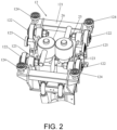
FIG. 2 is a partial structural schematic view of the moving carrier shown inFIG. 1 . -
FIG. 3 is a schematic view of the underwater cleaning device for marine life on the sealing surfaces of the gate shown inFIG. 1 during cleaning. -
FIG. 4 is a flow chart of a method for an underwater cleaning device for marine life on sealing surfaces of a gate according to an embodiment of the present invention. - In order to describe the technical content, structural features, achieved objects and effects of the present invention in detail, the following detailed description is given in conjunction with the embodiments and the accompanying drawings. Obviously, the embodiments described are only a part of the embodiments of the present invention, but not all of the embodiments. Based on the embodiments in the present invention, all other embodiments obtained by those of ordinary skill in the art without creative work fall within the protection scope of the present invention as defined by the appended claims.
- In the description of the present invention, it should be understood that the orientation or positional relationship indicated by the terms "upper", "lower", "left", "right", "vertical", "horizontal", "lateral", etc. is based on that shown in the drawings and is only for the convenience of describing the present invention and simplifying the description, and therefore should not be construed as a limitation on the protection content of the present invention.
- Referring to
FIGS. 1-3 , the present disclosure provides anunderwater cleaning device 100 for marine life on a sealing surface of a gate, which is adapted for connecting with a lifting device (not shown) and is movable in a vertical direction along abuilding structure 200 under the action of the lifting device, to clean up the marine life adhering to the sealing surface of the gate of thebuilding structure 200. Specifically, thedevice 100 includes amain structure 1, a cleaning structure installed on themain structure 1, and arigging structure 3 fixed to themain structure 1. Therigging structure 3 is configured to connect with the lifting device to drive themain structure 1 with the cleaning structure supported to move along thebuilding structure 200 to a corresponding position on the sealing surface of the gate, and the cleaning structure is configured to clean the marine life on the sealing surface of the gate when the cleaning structure moves to the corresponding position on the sealing surface of the gate. - In an embodiment, the opposite sides of the
main structure 1 are respectively provided with aguide member 13 for slidably matching with a guide rail (not shown) that is extended in a vertical direction and provided on both sides of the sealing surface of the gate. When theunderwater cleaning device 100 is subjected to the force of the lifting device, theguide member 13 can move in the vertical direction along the guide rail, so that theunderwater cleaning device 100 can stably move in the vertical direction along thebuilding structure 200, without jamming due to the marine life bred on the guide rails. Preferably, theguide member 13 is a guide wheel, which is not limited however. - It should be noted that, the lateral dimension of the
main structure 1 is adapted to those of thebuilding structure 200 and the guide rail, so as to ensure that theunderwater cleaning device 100 can operate in a limited space, and transfer a reaction force generated during the cleaning to the guide rails and thebuilding structure 200. Theguides 13 are sized to match the guide rails, which is beneficial to transfer the reaction force generated during the cleaning to the guide rails. In specific implementation, the lateral dimension of themain structure 1 can be adjusted adaptively according to the lateral dimension of the sealing surface of the gate to be cleaned, so that theunderwater cleaning device 100 can be suitable for cleaning different sealing surfaces of various lateral dimensions, especially for the sealing surfaces of large vertical gantry gates. - Referring to
FIG. 1 , the riggingstructure 3 includes a liftingring 31 for connecting with the lifting device, a plurality of liftingropes 32 connected with the liftingring 31, and adraw rod 33 connected to a lower end of the liftingrope 32, thedraw rod 33 is connected with themain structure 1, and has an adjustable length. By adjusting the length of thedraw rod 33, the force balance of the riggingstructure 3 is ensured, so that theunderwater cleaning device 100 can move stably along the guide rails under the action of the lifting device. More specifically, the liftingrope 32 is a stainless steel wire rope, and thedraw rod 33 is a basket draw rod. - Referring to
FIGS. 2-3 , the cleaning structure includes a nozzle structure (not shown) and a delivery pipe (not shown) configured to provide jetting fluid to the nozzle structure. Preferably, the nozzle structure is a cavitation nozzle structure, which uses strong force of micro-jet and shock waves generated by cavitation jet technology to remove the marine life. Such a structure is simple, which is suitable to effectively remove large-area marine life on the sealing surfaces of the gate. - Specifically, the sealing surfaces of the gate includes an
upper sealing surface 210 matching with the lintel of the gate, alower sealing surface 220 matching with the bottom of the gate, and a left sealing surface and a right sealing surface located on opposite sides of theupper sealing surface 210 and the lower sealing surface 220 (the four surfaces are formed like a door frame structure). Since the upper sealing surface 210 (vertical surface), the lower sealing surface 220 (horizontal surface), the left sealing surface (vertical surface) and the right sealing surface (vertical surface) are located in different planes, in this embodiment, different nozzles with different spray directions are applied to clean the four sealing surfaces, so that everywhere of the sealing surfaces of the gate may be cleaned without dead corners, thereby ensuring the cleaning effect of the sealing surfaces of the gate. Specifically, the nozzle structure includes afirst nozzle 21, asecond nozzle 22, athird nozzle 23 and afourth nozzle 24. Thefirst nozzle 21 is configured to clean the marine life on theupper sealing surface 210, and thesecond nozzle 22 is configured to clean the marine life on thelower sealing surface 220, thethird nozzle 23 is configured to clean the marine life on the left sealing surface, and thefourth nozzle 24 is configured to clean the marine life on the right sealing surface. Specifically, thefirst nozzle 21 is configured to jet fluid in a direction angled at 30-40 degrees relative to theupper sealing surface 210, thesecond nozzle 22 is configured to jet fluid in a direction angled at 30-40 degrees relative to thelower sealing surface 220, thethird nozzle 23 is configured to jet fluid in a direction angled at 30-40 degrees relative to the left sealing surface, and thefourth nozzle 24 is configured to jet fluid in a direction angled at 30-40 degrees relative to the right sealing surface, so as to optimized the cleaning effect. - Please refer to
FIG. 1 andFIG. 2 , themain structure 1 includes atruss 11 arranged laterally and a movingcarrier 12 slidably arranged on thetruss 11. Thefirst nozzle 21 and thesecond nozzle 22 are installed on the movingcarrier 12. When themain body structure 1 is driven by an external lifting device to reach theupper sealing surface 210 or thelower sealing surface 220, thefirst nozzle 21 and thesecond nozzle 22 carried by the movingcarrier 12 to move laterally along thetruss 11, so that theupper sealing surface 210 and thelower sealing surface 220 can be cleaned fully, to ensure the cleaning effect. Thetruss 11 includes atruss beam 111, aleft end beam 112 installed on the left side of thetruss beam 111, and aright end beam 113 installed on the right side of thetruss beam 111. Thethird nozzle 23 is installed on theleft end beam 112, and thefourth nozzle 24 is installed on theright end beam 113, when theunderwater cleaning device 100 moves in the vertical direction along the guide rail under the action of the lifting device, thethird nozzle 23 and thefourth nozzle 24 clean marine life on the left sealing surface and the left sealing surface respectively. - It is worth noting that, in this embodiment, the moving
carrier 12 will simultaneously drive thefirst nozzle 21 and thesecond nozzle 22 to move laterally along thetruss 11 when moving laterally along thetruss 11. In other embodiments, the movingcarrier 12 may also include a plurality of independent moving parts that can move laterally along thetruss 11, and thefirst nozzle 21 and thesecond nozzle 22 are independently installed on different moving parts, in such an arrangement, thefirst nozzle 21 and thesecond nozzle 22 can be driven by the moving parts respectively, so as to move laterally along thetruss 11. - More specifically, the moving
carrier 12 includes amain body 121, awheel 122 mounted on themain body 121, a drivingassembly 123, alateral limiting wheel 124 and a vertical limitingwheel 125. Themain body 121 is a welded structure, which is connected to thefirst nozzle 21 and thesecond nozzle 22 by bolts. Thewheel 122 is connected to the output end of thedrive assembly 123 and driven to move laterally along thetruss beam 111. In this embodiment, in thedrive assembly 123, dynamic and static technology is adopted, a motor is wrapped in the sealed cavity, and at the same time, compressed air is input into the sealed cavity, so that the sealed cavity maintains a slight positive pressure relative to the external environment. In such a way, the motor in the drivingassembly 123 is ensured to be worked normally in an environment with a water depth of 15 meters, to drive thewheels 122 normally. Thelateral limiting wheel 124 is configured to realize the lateral limit of thewheel 122, and thevertical limit wheel 125 is configured to realize the vertical limit of thewheel 122. In this embodiment, moving carrier, 12 is engaged with thetruss beam 111 by gear rack, which is not limited thereto. - Specifically, the cleaning structure further includes a
first valve 25 and asecond valve 26 installed on the movingcarrier 12, and athird valve 27 installed on thetruss 11. More specifically, thefirst valve 25 is configured to control the liquid outlet of thefirst nozzle 21, thesecond valve 26 is configured to control the fluid discharge of thesecond nozzle 22, and thethird valve 27 is configured to control the fluid discharge of thethird nozzle 23 and thefourth nozzle 24. That is to say, thefirst nozzle 21 and thesecond nozzle 22 are separately controlled by thefirst valve 25 and thesecond valve 26, and thethird nozzle 23 and thefourth nozzle 24 are simultaneously controlled by thethird valve 27, which is convenient for cleaning the left and the right sealing surfaces. Preferably, thefirst valve 25, thesecond valve 26 and thethird valve 27 are all electromagnetic valves, which is not limited thereto however. - Referring to
FIG.1 , the cleaning structure further includes areel device 28 mounted on thetruss beam 111, and thereel device 28 is configured to release or rewind the delivery pipe with the movement of the movingcarrier 12. Specifically, thereel device 28 uses a spring drive mechanism to realize the retraction of the delivery pipe. According to the invention, thereel device 28 includes areel body 281, aleft guide wheel 282 and aright guide wheel 283. The delivery pipe is wound on thereel body 281 and is located between theleft guide wheel 282 and theright guide wheel 283. In such a way, a desired delivery pipe can be ensured due to thereel body 281, and the delivery pipe can be bent to the left or right with a proper bending radius by means of theleft guide wheel 282 and theright guide wheel 283, and further the delivery pipe will not interfere with themain structure 1. - Please continue to refer to
FIG. 1 , specifically, theunderwater cleaning device 100 further includes a vision system having a camera device and afill light device 45 for providing a light source to the camera device. More specifically, the camera device includes apanoramic camera 41 mounted on the middle position of thetruss beam 111, aleft camera 42 mounted on theleft end beam 112, aright camera 43 mounted on theright end beam 113, and a movingcamera 44 mounted on the movingcarrier 12. The movingcamera 44 is configured to move laterally on thetruss beam 111 with the movingcarrier 12, collect underwater image information by eachcamera underwater cleaning device 100, observe the marine life on the sealing surfaces of the gate, and check the jet state of theunderwater cleaning device 100. Twofill light devices 45 is provided on theleft end beam 112 and theright end beam 113 respectively, so as to establish a full coverage light field, thereby realizing all-round high-definition monitoring of each sealing surface of the gate. Of course, in other embodiments, the twofill light devices 45 may also be installed at other positions of thetruss 11, and theleft camera 42 and theright camera 43 are not limited to be installed on theleft end beam 112 and theright end beam 113. - The present invention also provides an underwater cleaning device combination for marine life on the sealing surfaces of the gate, which is adapted for cleaning the marine life attached to the sealing surfaces of the gate of the
building structure 200. The device combination includes theunderwater cleaning device 100 according to the invention and two guide rails installed side by side on both sides of the sealing surfaces of the gate. Theunderwater cleaning device 100 includes amain structure 1, a cleaning structure installed on themain structure 1 for cleaning marine life, and a rigging structure fixed to themain structure 1. Twoguide members 13 are arranged at opposite sides of themain structure 1 for matching with the guide rails. The riggingstructure 3 is configured to connect with a lifting device to drive the cleaning structure to move to a corresponding position on the sealing surfaces of the gate, and thecleaning structure 1 is configured to clean the marine life on the sealing surfaces when the cleaning structure moves to the corresponding position on the sealing surfaces of the gate. The structures of theunderwater cleaning device 100 are as described above, and are not repeated here. - Hereinafter, the operation process of the
underwater cleaning device 100 for marine life on the sealing surfaces of the gate according to the present invention will be described with reference to the specific embodiments shown inFIGS. 1-3 . - Firstly, the lifting
ring 31 of theunderwater cleaning device 100 is hung on the hook of the lifting device, so that theunderwater cleaning device 100 is lifted and transferred above (on the water) the gate of thebuilding structure 200 to be cleaned. Next, the structural integrity of theunderwater cleaning device 100 is checked, after that, theunderwater cleaning device 100 is lowered into the water at a low speed, and the vision system is turned on to monitor the underwater image information; sequentially, theunderwater cleaning device 100 is continued to be lowered at a low speed to reach the bottom of the gate, during such a process, the growth of marine life on the sealing surfaces of the gate may be observed by the visual system. Then, theunderwater cleaning device 100 is lifted to theupper sealing surface 210 and stopped, thefirst valve 25 is turned on to control the movingcarrier 12 to move laterally on thetruss 11, and thefirst nozzle 21 sprays to clean the marine life on theupper sealing surface 210. Then, the movingcarrier 12 is controlled to rest in the middle of thetruss 11, and thefirst valve 25 is turned off. Then, thethird valve 27 is turned on, and theunderwater cleaning device 100 is lowered down at a low speed, and thethird nozzle 23 and thefourth nozzle 24 spray to clean the marine life on the left sealing surface and the right sealing surface until theunderwater cleaning device 100 is moved down to thelower sealing surface 220. Then, thethird valve 27 is turned off, and thesecond valve 26 is turned on to control the movingcarrier 12 to move laterally on thetruss 11, so that thesecond nozzle 22 spray to clean the marine life on thelower sealing surface 220. After the cleaning is completed, thesecond valve 26 is turned off and the movingcarrier 12 is controlled to rest in the middle of thetruss 11. Finally, theunderwater cleaning device 100 is lifted to move up the water surface along the track. Once the marine life are formed for a period of time, theunderwater cleaning device 100 will be lowered down into the water again to clean and the visual system will check the cleaning effect. - Referring to
FIG. 4 , the present invention also discloses an underwater cleaning method for marine life on the sealing surfaces of the gate, for cleaning the marine life attached to the sealing surfaces of the gate of the building structure, including the following steps: - S1, providing an
underwater cleaning device 100 for marine life on sealing surfaces of a gate, wherein theunderwater cleaning device 100 is as described above and includes amain structure 1, a cleaning structure installed on themain structure 1, and a riggingstructure 3 fixed to themain structure 1; - S2, connecting the rigging
structure 3 with a lifting device; - S3, driving the
underwater cleaning device 100 by the lifting device to move along thebuilding structure 200 to a position corresponding to the sealing surfaces of the gate; and - S4, cleaning the marine life on the sealing surfaces of the gate through the cleaning structure.
- Specifically, the underwater cleaning method further includes: installing two guide rails extended vertically on the building structure, the guide rails being located at two sides of the sealing surfaces of the gate; arranging two
guide members 13 at opposite sides of themain structure 1; and moving theguide members 13 along the guide rails while theunderwater cleaning device 100 moves downward along thebuilding structure 200 in step S3. With the cooperation of the guide rail and the guiding member, theunderwater cleaning device 100 can stably move in the vertical direction along thebuilding structure 200, without jamming due to the marine life bred on the guide rails. Preferably, theguide member 13 is a guide wheel, which is not limited thereto however. - Compared with the prior art, a new marine
life cleaning device 100 is provided, themain structure 1 is fixed with the riggingstructure 3, the cleaning structure is installed on themain structure 1, and the riggingstructure 3 is connected to the lifting device. In such an arrangement, theunderwater cleaning device 100 can be driven by the lifting device to move along thebuilding structure 200 to the position corresponding to the sealing surfaces of the gate, and then clean the marine life on the sealing surfaces by means of the cleaning structure, which has neither the inefficiency of the traditional cleaning method by divers nor the problems of poor movement stability of the cleaning device, and is applicable to the cleaning of marine life on the sealing surfaces of large gates. In addition, theunderwater cleaning device 100 of the present invention is applicable to sealing surfaces of different gates with various sizes and various materials, without any material restriction of thebuilding structure 200, to obtain good applicability. Furthermore, there is no need to move themain structure 1 on the cleaning structure, which is applicable to perform cleanup on sharp edges and corners, and multiple planes.
Claims (11)
- An underwater cleaning device (100) for marine life on sealing surfaces of a gate, adapted for cleaning marine life attached to sealing surfaces of a gate of a building structure (200), the underwater cleaning device (100) comprising a main structure (1), a cleaning structure installed on the main structure (1), and a rigging structure (3) fixed to the main structure (1), wherein the rigging structure (3) is connected with a lifting device to drive the cleaning structure to move to a corresponding position on the sealing surfaces of the gate, and the cleaning structure is configured to clean the marine life on the sealing surfaces of the gate when the cleaning structure moves to the corresponding position on the sealing surfaces of the gate;wherein the main structure (1) comprises a truss (11) arranged laterally and a moving carrier (12) slidably provided on the truss (11), the cleaning structure comprises a nozzle structure, a delivery pipe and a reel device (28), the delivery pipe is configured to provide jetting fluid to the nozzle structure, the nozzle structure comprises a first nozzle (21) for cleaning an upper sealing surface (210) of the sealing surfaces and a second nozzle (22) for cleaning a lower sealing surface (220) of the sealing surfaces, and the first nozzle (21) and the second nozzle (22) are mounted on the moving carrier (12);the reel device (28) is mounted on the truss (111) characterized in that the reel device (28) is configured to release or rewind the delivery pipe with a movement of the moving carrier (12), and the reel device (28) comprises a reel body (281), a left guide wheel (282) and a right guide wheel (283), the delivery pipe is wound on the reel body (281) and is located between the left guide wheel (282) and the right guide wheel (283) .
- The underwater cleaning device according to claim 1, wherein opposite sides of the main structure (1) are respectively provided with a guide member (13) for slidably matching with a guide rail that is extended in a vertical direction and provided on both sides of the sealing surfaces of the gate.
- The underwater cleaning device according to claim 1 or claim 2, wherein the nozzle structure is configured to jet fluid in a direction angled at 30-40 degrees relative to the sealing surfaces of the gate.
- The underwater cleaning device according to claim 1 or claim 2, wherein the nozzle structure is a cavitation nozzle structure.
- The underwater cleaning device according to claim 1 or claim 2, wherein the nozzle structure further comprises a third nozzle (23) and a fourth nozzle (24) respectively for cleaning a left sealing surface and a right sealing surface of the sealing surfaces, and the third nozzle (23) and the fourth nozzle (24) are mounted on left and right sides of the moving carrier (12) respectively.
- The underwater cleaning device according to claim 5, wherein the cleaning structure further comprises a first valve (25) for controlling fluid discharge of the first nozzle (21), a second valve (26) for controlling fluid discharge of the second nozzle (22), and a third valve (27) for control fluid discharge of the third nozzle (23) and the fourth nozzle (24).
- The underwater cleaning device according to claim 1 or claim 2, further comprising a vision system, wherein the vision system comprises a camera device for collecting underwater image information and at least two fill light devices (45) for providing light sources to the camera device, the fill light devices (45) are respectively installed on left and right sides of the truss (11); the camera device comprises a panoramic camera (41) installed in a middle of the truss (11), a left camera (42) and a right camera (43) installed on the left and right sides of the truss (11), and a moving camera (44) installed on the moving carrier (12).
- The underwater cleaning device according to claim 1, wherein the rigging structure (3) comprises a lifting ring (31) for connecting with the lifting device, a plurality of lifting ropes (32) connected with the lifting ring (31), and a draw rod (33) connected to a lower end of the lifting rope (32), the draw rod (33) is connected with the main structure (1) and has an adjustable length.
- An underwater cleaning device combination for marine life on sealing surfaces of a gate, adapted for cleaning marine life attached to sealing surfaces of a gate of a building structure (200), the underwater cleaning device combination comprising an underwater cleaning device (100) for marine life on sealing surfaces of a gate according to any of the claims 1 to 8 and two guide rails, the guide rails being installed side by side on both sides of the sealing surfaces of the gate, wherein opposite sides of the main structure (1) are respectively provided with a guide member (13) for slidably matching with the guide rails.
- An underwater cleaning method for marine life on sealing surfaces of a gate, adapted for cleaning marine life attached to sealing surfaces of a gate of a building structure, the under cleaning method comprising steps of:S1, providing an underwater cleaning device (100) for marine life on sealing surfaces of a gate, the underwater cleaning device (100) comprising a main structure (1), a cleaning structure installed on the main structure (1), and a rigging structure (3) fixed to the main structure (1);S2, connecting the rigging structure (3) with a lifting device;S3, driving the underwater cleaning device (100) by the lifting device to move along the building structure (200) to a position corresponding to the sealing surfaces of the gate; andS4, cleaning the marine life on the sealing surfaces of the gate through the cleaning structure;wherein the main structure (1) comprises a truss (11) arranged laterally and a moving carrier (12) slidably provided on the truss (11), the cleaning structure comprises a nozzle structure, a delivery pipe and a reel device (28), the delivery pipe is configured to provide jetting fluid to the nozzle structure, the nozzle structure comprises a first nozzle (21) for cleaning an upper sealing surface (210) of the sealing surfaces and a second nozzle (22) for cleaning a lower sealing surface (220) of the sealing surfaces, and the first nozzle (21) and the second nozzle (22) are mounted on the moving carrier (12); characterized in that, the reel device (28) is mounted on the truss (111) and configured to release or rewind the delivery pipe with a movement of the moving carrier (12), and the reel device (28) comprises a reel body (281), a left guide wheel (282) and a right guide wheel (283), the delivery pipe is wound on the reel body (281) and is located between the left guide wheel (282) and the right guide wheel (283).
- The underwater cleaning method according to claim 10, further comprising:installing two guide rails extended vertically on the building structure (200), the guide rails being located at two sides of the sealing surfaces of the gate;arranging two guide members (13) at opposite sides of the main structure (1); andmoving the guide members (13) along the guide rails while the underwater cleaning device (100) moves downward along the building structure (200) in step S3.
Applications Claiming Priority (2)
| Application Number | Priority Date | Filing Date | Title |
|---|---|---|---|
| CN201911210063.9A CN111112180B (en) | 2019-11-29 | 2019-11-29 | Underwater cleaning equipment, equipment combination and cleaning method for sea creatures on gate sealing surface |
| PCT/CN2020/090859 WO2021103438A1 (en) | 2019-11-29 | 2020-05-18 | Underwater cleaning device for marine life on sealing surface of gate, and device combination and cleaning method |
Publications (3)
| Publication Number | Publication Date |
|---|---|
| EP4035784A1 EP4035784A1 (en) | 2022-08-03 |
| EP4035784A4 EP4035784A4 (en) | 2022-12-21 |
| EP4035784B1 true EP4035784B1 (en) | 2025-05-07 |
Family
ID=70496531
Family Applications (1)
| Application Number | Title | Priority Date | Filing Date |
|---|---|---|---|
| EP20892652.7A Active EP4035784B1 (en) | 2019-11-29 | 2020-05-18 | Underwater cleaning device for marine life on sealing surface of gate, and device combination and cleaning method |
Country Status (4)
| Country | Link |
|---|---|
| EP (1) | EP4035784B1 (en) |
| JP (1) | JP7400087B2 (en) |
| CN (1) | CN111112180B (en) |
| WO (1) | WO2021103438A1 (en) |
Families Citing this family (9)
| Publication number | Priority date | Publication date | Assignee | Title |
|---|---|---|---|---|
| CN111112180B (en) * | 2019-11-29 | 2021-08-17 | 中广核研究院有限公司 | Underwater cleaning equipment, equipment combination and cleaning method for sea creatures on gate sealing surface |
| CN114011775B (en) * | 2021-10-21 | 2023-07-14 | 广东行远机器人技术有限公司 | Pump house gate sealing area cleaning method, system and computer readable storage medium |
| CN114011776A (en) * | 2021-10-21 | 2022-02-08 | 广东行远机器人技术有限公司 | Underwater cleaning robot and underwater cleaning system |
| CN118080434A (en) * | 2022-11-28 | 2024-05-28 | 中核武汉核电运行技术股份有限公司 | A cleaning device for gate rails and their sealing surfaces |
| CN116140249A (en) * | 2022-12-28 | 2023-05-23 | 中核武汉核电运行技术股份有限公司 | Seawater system gate slot cleaning device, system and method |
| CN117364716A (en) * | 2023-10-12 | 2024-01-09 | 南通展宇节能环保技术有限公司 | Self-cleaning sluice device for hydraulic engineering |
| CN119158825A (en) * | 2024-11-21 | 2024-12-20 | 新河县黄河水利机械有限公司 | A water conservancy project gate cleaning and maintenance device |
| CN120305801B (en) * | 2025-05-30 | 2025-10-28 | 聊城雅居乐环保科技有限公司 | Cleaning device for activated carbon adsorption box |
| CN120482943B (en) * | 2025-07-14 | 2025-09-19 | 中铁建大桥工程局集团靖江重工有限公司 | An aerial posture-adjustable lifting sling for a beam moving machine |
Family Cites Families (17)
| Publication number | Priority date | Publication date | Assignee | Title |
|---|---|---|---|---|
| JPS49110370U (en) * | 1973-01-17 | 1974-09-20 | ||
| JPS568691U (en) * | 1979-07-02 | 1981-01-24 | ||
| JPS57140253U (en) * | 1981-02-27 | 1982-09-02 | ||
| JPS62112807A (en) * | 1985-11-13 | 1987-05-23 | Ishikawajima Harima Heavy Ind Co Ltd | Underwater work equipment |
| JPH0776446B2 (en) * | 1988-06-07 | 1995-08-16 | 丸誠重工業株式会社 | Device for cleaning the gutter of a corner-cutting gate |
| JPH02298390A (en) * | 1989-05-12 | 1990-12-10 | Masaaki Kanzawa | Wall surface maintenance apparatus |
| JP3013768U (en) | 1995-01-20 | 1995-07-18 | チャン カイ−クオ | Building exterior wall washer |
| JP3318249B2 (en) * | 1997-12-26 | 2002-08-26 | 株式会社奥村組 | Underwater cleaning device |
| JP2007326010A (en) | 2006-06-07 | 2007-12-20 | Hitachi Ltd | Cleaning device and cleaning method in structure in which liquid is put |
| US9839925B2 (en) | 2012-09-11 | 2017-12-12 | Ge-Hitachi Nuclear Energy Americas Llc | Methods of cleaning a submerged surface using a fluid jet discharging a liquid/gas combination |
| CN106269623B (en) * | 2016-09-06 | 2018-07-06 | 吉林大学 | A kind of frame-type PX pumping plants sluice gate guide rail automatic cleaning machine |
| CN106475364B (en) * | 2016-12-21 | 2018-10-26 | 中国海洋石油总公司 | A kind of encircling type underwater steel construction pipeline external surface marine growth cleaning robot |
| CN107100222B (en) * | 2017-05-25 | 2022-05-13 | 武汉大学 | Construction diversion tunnel bottom gate way silt sand cleaning device |
| CN207436018U (en) * | 2017-10-31 | 2018-06-01 | 扬州天朗水务设备有限公司 | A kind of new Stoplog gate Zhua Luo mechanisms |
| JP2019177300A (en) | 2018-03-30 | 2019-10-17 | 株式会社Ihi | Base conditioning device of underwater metal structure |
| CN109985850A (en) * | 2019-04-26 | 2019-07-09 | 山东交通学院 | A device for removing marine organisms from the surface of a pile-type offshore platform column |
| CN111112180B (en) * | 2019-11-29 | 2021-08-17 | 中广核研究院有限公司 | Underwater cleaning equipment, equipment combination and cleaning method for sea creatures on gate sealing surface |
-
2019
- 2019-11-29 CN CN201911210063.9A patent/CN111112180B/en active Active
-
2020
- 2020-05-18 JP JP2022517991A patent/JP7400087B2/en active Active
- 2020-05-18 WO PCT/CN2020/090859 patent/WO2021103438A1/en not_active Ceased
- 2020-05-18 EP EP20892652.7A patent/EP4035784B1/en active Active
Also Published As
| Publication number | Publication date |
|---|---|
| EP4035784A4 (en) | 2022-12-21 |
| EP4035784A1 (en) | 2022-08-03 |
| CN111112180A (en) | 2020-05-08 |
| JP7400087B2 (en) | 2023-12-18 |
| WO2021103438A1 (en) | 2021-06-03 |
| JP2022549421A (en) | 2022-11-25 |
| CN111112180B (en) | 2021-08-17 |
Similar Documents
| Publication | Publication Date | Title |
|---|---|---|
| EP4035784A1 (en) | Underwater cleaning device for marine life on sealing surface of gate, and device combination and cleaning method | |
| CN106269623B (en) | A kind of frame-type PX pumping plants sluice gate guide rail automatic cleaning machine | |
| KR100971666B1 (en) | Robot for internal exploration and operation of piping | |
| CN113427491B (en) | Wall climbing type pipeline outer surface encircling inspection/cleaning robot and pipeline surface cleaning method | |
| CN113426768B (en) | Pipeline outer wall cleaning robot | |
| CA2671156A1 (en) | Method and apparatus for cleaning a substantially vertical surface | |
| CN104801509A (en) | Electrified water-washing operation device for electrical equipment | |
| CA2730790A1 (en) | Top-down hydro-demolition system with rigid support frame | |
| KR102198788B1 (en) | Dron for Cleaning | |
| DE4415434C2 (en) | Automatic cleaning device for window and / or facade surfaces | |
| CN204602697U (en) | For the living water washing implement of electrical equipment | |
| CN110547719A (en) | Automatic cleaning robot for glass curtain wall | |
| JP6839965B2 (en) | Manipulator device | |
| CN115320842B (en) | Flaw detection and repair integrated unmanned aerial vehicle and working method thereof | |
| CN115369760B (en) | A bridge main body maintenance machine | |
| WO2016036254A1 (en) | Crawler configured for submarine use | |
| CN118253457B (en) | Ship body surface treatment device for ship maintenance | |
| KR100858279B1 (en) | Automatic supply and recovery of paint hose for painting work inside the hull and its control method | |
| CN218562082U (en) | Bridge main body overhaul machine | |
| CN111451200A (en) | Automatic cleaning system for sealing surface of underwater gate | |
| CN218292747U (en) | Steel construction canopy glass installation removes and hangs basket | |
| KR101059509B1 (en) | Automatic supply and recovery of hose | |
| KR20170043379A (en) | An Operation Tool for Outer Walls of a Building and Gondola Unit Comprising the Operation Tool | |
| KR20210010050A (en) | Ship block outside blasting apparatus | |
| CN116748048A (en) | Ship cabin intelligent spraying system |
Legal Events
| Date | Code | Title | Description |
|---|---|---|---|
| STAA | Information on the status of an ep patent application or granted ep patent |
Free format text: STATUS: THE INTERNATIONAL PUBLICATION HAS BEEN MADE |
|
| PUAI | Public reference made under article 153(3) epc to a published international application that has entered the european phase |
Free format text: ORIGINAL CODE: 0009012 |
|
| STAA | Information on the status of an ep patent application or granted ep patent |
Free format text: STATUS: REQUEST FOR EXAMINATION WAS MADE |
|
| 17P | Request for examination filed |
Effective date: 20220425 |
|
| AK | Designated contracting states |
Kind code of ref document: A1 Designated state(s): AL AT BE BG CH CY CZ DE DK EE ES FI FR GB GR HR HU IE IS IT LI LT LU LV MC MK MT NL NO PL PT RO RS SE SI SK SM TR |
|
| REG | Reference to a national code |
Ref country code: DE Ref legal event code: R079 Free format text: PREVIOUS MAIN CLASS: B08B0003020000 Ipc: E02B0008000000 Ref document number: 602020051069 Country of ref document: DE |
|
| A4 | Supplementary search report drawn up and despatched |
Effective date: 20221123 |
|
| RIC1 | Information provided on ipc code assigned before grant |
Ipc: B63B 59/08 20060101ALN20221117BHEP Ipc: E02B 7/54 20060101ALN20221117BHEP Ipc: B66C 1/66 20060101ALI20221117BHEP Ipc: B66C 1/16 20060101ALI20221117BHEP Ipc: B08B 3/02 20060101ALI20221117BHEP Ipc: E02B 8/00 20060101AFI20221117BHEP |
|
| DAV | Request for validation of the european patent (deleted) | ||
| DAX | Request for extension of the european patent (deleted) | ||
| RIN1 | Information on inventor provided before grant (corrected) |
Inventor name: YU, BING Inventor name: CHEN, JIAJIE Inventor name: ZHANG, MEILING Inventor name: LI, ZHI Inventor name: LIU, GANG Inventor name: ZHOU, GUOFENG Inventor name: WU, YU Inventor name: ZHAO, APENG Inventor name: ZHU, JIANLIN |
|
| GRAP | Despatch of communication of intention to grant a patent |
Free format text: ORIGINAL CODE: EPIDOSNIGR1 |
|
| STAA | Information on the status of an ep patent application or granted ep patent |
Free format text: STATUS: GRANT OF PATENT IS INTENDED |
|
| INTG | Intention to grant announced |
Effective date: 20250217 |
|
| GRAS | Grant fee paid |
Free format text: ORIGINAL CODE: EPIDOSNIGR3 |
|
| GRAA | (expected) grant |
Free format text: ORIGINAL CODE: 0009210 |
|
| STAA | Information on the status of an ep patent application or granted ep patent |
Free format text: STATUS: THE PATENT HAS BEEN GRANTED |
|
| AK | Designated contracting states |
Kind code of ref document: B1 Designated state(s): AL AT BE BG CH CY CZ DE DK EE ES FI FR GB GR HR HU IE IS IT LI LT LU LV MC MK MT NL NO PL PT RO RS SE SI SK SM TR |
|
| REG | Reference to a national code |
Ref country code: GB Ref legal event code: FG4D |
|
| REG | Reference to a national code |
Ref country code: CH Ref legal event code: EP |
|
| REG | Reference to a national code |
Ref country code: DE Ref legal event code: R096 Ref document number: 602020051069 Country of ref document: DE |
|
| REG | Reference to a national code |
Ref country code: IE Ref legal event code: FG4D |
|
| PGFP | Annual fee paid to national office [announced via postgrant information from national office to epo] |
Ref country code: GB Payment date: 20250620 Year of fee payment: 6 |
|
| PGFP | Annual fee paid to national office [announced via postgrant information from national office to epo] |
Ref country code: FR Payment date: 20250620 Year of fee payment: 6 |
|
| REG | Reference to a national code |
Ref country code: NL Ref legal event code: MP Effective date: 20250507 |
|
| PG25 | Lapsed in a contracting state [announced via postgrant information from national office to epo] |
Ref country code: PT Free format text: LAPSE BECAUSE OF FAILURE TO SUBMIT A TRANSLATION OF THE DESCRIPTION OR TO PAY THE FEE WITHIN THE PRESCRIBED TIME-LIMIT Effective date: 20250908 Ref country code: ES Free format text: LAPSE BECAUSE OF FAILURE TO SUBMIT A TRANSLATION OF THE DESCRIPTION OR TO PAY THE FEE WITHIN THE PRESCRIBED TIME-LIMIT Effective date: 20250507 Ref country code: FI Free format text: LAPSE BECAUSE OF FAILURE TO SUBMIT A TRANSLATION OF THE DESCRIPTION OR TO PAY THE FEE WITHIN THE PRESCRIBED TIME-LIMIT Effective date: 20250507 |
|
| REG | Reference to a national code |
Ref country code: LT Ref legal event code: MG9D |
|
| PG25 | Lapsed in a contracting state [announced via postgrant information from national office to epo] |
Ref country code: NO Free format text: LAPSE BECAUSE OF FAILURE TO SUBMIT A TRANSLATION OF THE DESCRIPTION OR TO PAY THE FEE WITHIN THE PRESCRIBED TIME-LIMIT Effective date: 20250807 Ref country code: GR Free format text: LAPSE BECAUSE OF FAILURE TO SUBMIT A TRANSLATION OF THE DESCRIPTION OR TO PAY THE FEE WITHIN THE PRESCRIBED TIME-LIMIT Effective date: 20250808 |
|
| PG25 | Lapsed in a contracting state [announced via postgrant information from national office to epo] |
Ref country code: PL Free format text: LAPSE BECAUSE OF FAILURE TO SUBMIT A TRANSLATION OF THE DESCRIPTION OR TO PAY THE FEE WITHIN THE PRESCRIBED TIME-LIMIT Effective date: 20250507 Ref country code: NL Free format text: LAPSE BECAUSE OF FAILURE TO SUBMIT A TRANSLATION OF THE DESCRIPTION OR TO PAY THE FEE WITHIN THE PRESCRIBED TIME-LIMIT Effective date: 20250507 |
|
| REG | Reference to a national code |
Ref country code: AT Ref legal event code: MK05 Ref document number: 1792586 Country of ref document: AT Kind code of ref document: T Effective date: 20250507 |
|
| PG25 | Lapsed in a contracting state [announced via postgrant information from national office to epo] |
Ref country code: BG Free format text: LAPSE BECAUSE OF FAILURE TO SUBMIT A TRANSLATION OF THE DESCRIPTION OR TO PAY THE FEE WITHIN THE PRESCRIBED TIME-LIMIT Effective date: 20250507 |
|
| PG25 | Lapsed in a contracting state [announced via postgrant information from national office to epo] |
Ref country code: HR Free format text: LAPSE BECAUSE OF FAILURE TO SUBMIT A TRANSLATION OF THE DESCRIPTION OR TO PAY THE FEE WITHIN THE PRESCRIBED TIME-LIMIT Effective date: 20250507 |
|
| PG25 | Lapsed in a contracting state [announced via postgrant information from national office to epo] |
Ref country code: AT Free format text: LAPSE BECAUSE OF FAILURE TO SUBMIT A TRANSLATION OF THE DESCRIPTION OR TO PAY THE FEE WITHIN THE PRESCRIBED TIME-LIMIT Effective date: 20250507 |
|
| PG25 | Lapsed in a contracting state [announced via postgrant information from national office to epo] |
Ref country code: RS Free format text: LAPSE BECAUSE OF FAILURE TO SUBMIT A TRANSLATION OF THE DESCRIPTION OR TO PAY THE FEE WITHIN THE PRESCRIBED TIME-LIMIT Effective date: 20250807 |
|
| PG25 | Lapsed in a contracting state [announced via postgrant information from national office to epo] |
Ref country code: IS Free format text: LAPSE BECAUSE OF FAILURE TO SUBMIT A TRANSLATION OF THE DESCRIPTION OR TO PAY THE FEE WITHIN THE PRESCRIBED TIME-LIMIT Effective date: 20250907 |
|
| PG25 | Lapsed in a contracting state [announced via postgrant information from national office to epo] |
Ref country code: LV Free format text: LAPSE BECAUSE OF FAILURE TO SUBMIT A TRANSLATION OF THE DESCRIPTION OR TO PAY THE FEE WITHIN THE PRESCRIBED TIME-LIMIT Effective date: 20250507 |
|
| REG | Reference to a national code |
Ref country code: DE Ref legal event code: R119 Ref document number: 602020051069 Country of ref document: DE |
|
| REG | Reference to a national code |
Ref country code: CH Ref legal event code: H13 Free format text: ST27 STATUS EVENT CODE: U-0-0-H10-H13 (AS PROVIDED BY THE NATIONAL OFFICE) Effective date: 20251223 |
|
| PG25 | Lapsed in a contracting state [announced via postgrant information from national office to epo] |
Ref country code: SM Free format text: LAPSE BECAUSE OF FAILURE TO SUBMIT A TRANSLATION OF THE DESCRIPTION OR TO PAY THE FEE WITHIN THE PRESCRIBED TIME-LIMIT Effective date: 20250507 Ref country code: DK Free format text: LAPSE BECAUSE OF FAILURE TO SUBMIT A TRANSLATION OF THE DESCRIPTION OR TO PAY THE FEE WITHIN THE PRESCRIBED TIME-LIMIT Effective date: 20250507 |
|
| PG25 | Lapsed in a contracting state [announced via postgrant information from national office to epo] |
Ref country code: LU Free format text: LAPSE BECAUSE OF NON-PAYMENT OF DUE FEES Effective date: 20250518 |
|
| PG25 | Lapsed in a contracting state [announced via postgrant information from national office to epo] |
Ref country code: CH Free format text: LAPSE BECAUSE OF NON-PAYMENT OF DUE FEES Effective date: 20250531 |
|
| PG25 | Lapsed in a contracting state [announced via postgrant information from national office to epo] |
Ref country code: CZ Free format text: LAPSE BECAUSE OF FAILURE TO SUBMIT A TRANSLATION OF THE DESCRIPTION OR TO PAY THE FEE WITHIN THE PRESCRIBED TIME-LIMIT Effective date: 20250507 |
|
| PG25 | Lapsed in a contracting state [announced via postgrant information from national office to epo] |
Ref country code: EE Free format text: LAPSE BECAUSE OF FAILURE TO SUBMIT A TRANSLATION OF THE DESCRIPTION OR TO PAY THE FEE WITHIN THE PRESCRIBED TIME-LIMIT Effective date: 20250507 |
|
| PG25 | Lapsed in a contracting state [announced via postgrant information from national office to epo] |
Ref country code: SK Free format text: LAPSE BECAUSE OF FAILURE TO SUBMIT A TRANSLATION OF THE DESCRIPTION OR TO PAY THE FEE WITHIN THE PRESCRIBED TIME-LIMIT Effective date: 20250507 |
|
| PG25 | Lapsed in a contracting state [announced via postgrant information from national office to epo] |
Ref country code: IT Free format text: LAPSE BECAUSE OF FAILURE TO SUBMIT A TRANSLATION OF THE DESCRIPTION OR TO PAY THE FEE WITHIN THE PRESCRIBED TIME-LIMIT Effective date: 20250507 |
|
| REG | Reference to a national code |
Ref country code: BE Ref legal event code: MM Effective date: 20250531 |
|
| PG25 | Lapsed in a contracting state [announced via postgrant information from national office to epo] |
Ref country code: RO Free format text: LAPSE BECAUSE OF FAILURE TO SUBMIT A TRANSLATION OF THE DESCRIPTION OR TO PAY THE FEE WITHIN THE PRESCRIBED TIME-LIMIT Effective date: 20250507 |
|
| PG25 | Lapsed in a contracting state [announced via postgrant information from national office to epo] |
Ref country code: MC Free format text: LAPSE BECAUSE OF FAILURE TO SUBMIT A TRANSLATION OF THE DESCRIPTION OR TO PAY THE FEE WITHIN THE PRESCRIBED TIME-LIMIT Effective date: 20250507 |
|
| PLBE | No opposition filed within time limit |
Free format text: ORIGINAL CODE: 0009261 |
|
| STAA | Information on the status of an ep patent application or granted ep patent |
Free format text: STATUS: NO OPPOSITION FILED WITHIN TIME LIMIT |
|
| REG | Reference to a national code |
Ref country code: CH Ref legal event code: L10 Free format text: ST27 STATUS EVENT CODE: U-0-0-L10-L00 (AS PROVIDED BY THE NATIONAL OFFICE) Effective date: 20260318 |
|
| PG25 | Lapsed in a contracting state [announced via postgrant information from national office to epo] |
Ref country code: IE Free format text: LAPSE BECAUSE OF NON-PAYMENT OF DUE FEES Effective date: 20250518 Ref country code: DE Free format text: LAPSE BECAUSE OF NON-PAYMENT OF DUE FEES Effective date: 20251202 |
|
| 26N | No opposition filed |
Effective date: 20260210 |
|
| PG25 | Lapsed in a contracting state [announced via postgrant information from national office to epo] |
Ref country code: BE Free format text: LAPSE BECAUSE OF NON-PAYMENT OF DUE FEES Effective date: 20250531 |