EP4035620A1 - Surgical system and display method - Google Patents
Surgical system and display method Download PDFInfo
- Publication number
- EP4035620A1 EP4035620A1 EP22153651.9A EP22153651A EP4035620A1 EP 4035620 A1 EP4035620 A1 EP 4035620A1 EP 22153651 A EP22153651 A EP 22153651A EP 4035620 A1 EP4035620 A1 EP 4035620A1
- Authority
- EP
- European Patent Office
- Prior art keywords
- screen
- area
- endoscope
- center
- length
- Prior art date
- Legal status (The legal status is an assumption and is not a legal conclusion. Google has not performed a legal analysis and makes no representation as to the accuracy of the status listed.)
- Pending
Links
Images


Classifications
-
- A—HUMAN NECESSITIES
- A61—MEDICAL OR VETERINARY SCIENCE; HYGIENE
- A61B—DIAGNOSIS; SURGERY; IDENTIFICATION
- A61B34/00—Computer-aided surgery; Manipulators or robots specially adapted for use in surgery
- A61B34/25—User interfaces for surgical systems
-
- A—HUMAN NECESSITIES
- A61—MEDICAL OR VETERINARY SCIENCE; HYGIENE
- A61B—DIAGNOSIS; SURGERY; IDENTIFICATION
- A61B1/00—Instruments for performing medical examinations of the interior of cavities or tubes of the body by visual or photographical inspection, e.g. endoscopes; Illuminating arrangements therefor
- A61B1/00002—Operational features of endoscopes
- A61B1/00039—Operational features of endoscopes provided with input arrangements for the user
- A61B1/0004—Operational features of endoscopes provided with input arrangements for the user for electronic operation
-
- A—HUMAN NECESSITIES
- A61—MEDICAL OR VETERINARY SCIENCE; HYGIENE
- A61B—DIAGNOSIS; SURGERY; IDENTIFICATION
- A61B1/00—Instruments for performing medical examinations of the interior of cavities or tubes of the body by visual or photographical inspection, e.g. endoscopes; Illuminating arrangements therefor
- A61B1/00002—Operational features of endoscopes
- A61B1/00043—Operational features of endoscopes provided with output arrangements
- A61B1/00045—Display arrangement
- A61B1/0005—Display arrangement combining images e.g. side-by-side, superimposed or tiled
-
- A—HUMAN NECESSITIES
- A61—MEDICAL OR VETERINARY SCIENCE; HYGIENE
- A61B—DIAGNOSIS; SURGERY; IDENTIFICATION
- A61B1/00—Instruments for performing medical examinations of the interior of cavities or tubes of the body by visual or photographical inspection, e.g. endoscopes; Illuminating arrangements therefor
- A61B1/00147—Holding or positioning arrangements
- A61B1/00149—Holding or positioning arrangements using articulated arms
-
- A—HUMAN NECESSITIES
- A61—MEDICAL OR VETERINARY SCIENCE; HYGIENE
- A61B—DIAGNOSIS; SURGERY; IDENTIFICATION
- A61B34/00—Computer-aided surgery; Manipulators or robots specially adapted for use in surgery
- A61B34/30—Surgical robots
-
- A—HUMAN NECESSITIES
- A61—MEDICAL OR VETERINARY SCIENCE; HYGIENE
- A61B—DIAGNOSIS; SURGERY; IDENTIFICATION
- A61B34/00—Computer-aided surgery; Manipulators or robots specially adapted for use in surgery
- A61B34/30—Surgical robots
- A61B34/37—Master-slave robots
-
- A—HUMAN NECESSITIES
- A61—MEDICAL OR VETERINARY SCIENCE; HYGIENE
- A61B—DIAGNOSIS; SURGERY; IDENTIFICATION
- A61B90/00—Instruments, implements or accessories specially adapted for surgery or diagnosis and not covered by any of the groups A61B1/00 - A61B50/00, e.g. for luxation treatment or for protecting wound edges
- A61B90/36—Image-producing devices or illumination devices not otherwise provided for
- A61B90/361—Image-producing devices, e.g. surgical cameras
-
- G—PHYSICS
- G16—INFORMATION AND COMMUNICATION TECHNOLOGY [ICT] SPECIALLY ADAPTED FOR SPECIFIC APPLICATION FIELDS
- G16H—HEALTHCARE INFORMATICS, i.e. INFORMATION AND COMMUNICATION TECHNOLOGY [ICT] SPECIALLY ADAPTED FOR THE HANDLING OR PROCESSING OF MEDICAL OR HEALTHCARE DATA
- G16H20/00—ICT specially adapted for therapies or health-improving plans, e.g. for handling prescriptions, for steering therapy or for monitoring patient compliance
- G16H20/40—ICT specially adapted for therapies or health-improving plans, e.g. for handling prescriptions, for steering therapy or for monitoring patient compliance relating to mechanical, radiation or invasive therapies, e.g. surgery, laser therapy, dialysis or acupuncture
-
- G—PHYSICS
- G16—INFORMATION AND COMMUNICATION TECHNOLOGY [ICT] SPECIALLY ADAPTED FOR SPECIFIC APPLICATION FIELDS
- G16H—HEALTHCARE INFORMATICS, i.e. INFORMATION AND COMMUNICATION TECHNOLOGY [ICT] SPECIALLY ADAPTED FOR THE HANDLING OR PROCESSING OF MEDICAL OR HEALTHCARE DATA
- G16H40/00—ICT specially adapted for the management or administration of healthcare resources or facilities; ICT specially adapted for the management or operation of medical equipment or devices
- G16H40/60—ICT specially adapted for the management or administration of healthcare resources or facilities; ICT specially adapted for the management or operation of medical equipment or devices for the operation of medical equipment or devices
- G16H40/67—ICT specially adapted for the management or administration of healthcare resources or facilities; ICT specially adapted for the management or operation of medical equipment or devices for the operation of medical equipment or devices for remote operation
-
- A—HUMAN NECESSITIES
- A61—MEDICAL OR VETERINARY SCIENCE; HYGIENE
- A61B—DIAGNOSIS; SURGERY; IDENTIFICATION
- A61B17/00—Surgical instruments, devices or methods, e.g. tourniquets
- A61B2017/00973—Surgical instruments, devices or methods, e.g. tourniquets pedal-operated
-
- A—HUMAN NECESSITIES
- A61—MEDICAL OR VETERINARY SCIENCE; HYGIENE
- A61B—DIAGNOSIS; SURGERY; IDENTIFICATION
- A61B34/00—Computer-aided surgery; Manipulators or robots specially adapted for use in surgery
- A61B34/20—Surgical navigation systems; Devices for tracking or guiding surgical instruments, e.g. for frameless stereotaxis
- A61B2034/2046—Tracking techniques
- A61B2034/2059—Mechanical position encoders
-
- A—HUMAN NECESSITIES
- A61—MEDICAL OR VETERINARY SCIENCE; HYGIENE
- A61B—DIAGNOSIS; SURGERY; IDENTIFICATION
- A61B34/00—Computer-aided surgery; Manipulators or robots specially adapted for use in surgery
- A61B34/30—Surgical robots
- A61B2034/301—Surgical robots for introducing or steering flexible instruments inserted into the body, e.g. catheters or endoscopes
-
- A—HUMAN NECESSITIES
- A61—MEDICAL OR VETERINARY SCIENCE; HYGIENE
- A61B—DIAGNOSIS; SURGERY; IDENTIFICATION
- A61B34/00—Computer-aided surgery; Manipulators or robots specially adapted for use in surgery
- A61B34/30—Surgical robots
- A61B2034/302—Surgical robots specifically adapted for manipulations within body cavities, e.g. within abdominal or thoracic cavities
-
- A—HUMAN NECESSITIES
- A61—MEDICAL OR VETERINARY SCIENCE; HYGIENE
- A61B—DIAGNOSIS; SURGERY; IDENTIFICATION
- A61B34/00—Computer-aided surgery; Manipulators or robots specially adapted for use in surgery
- A61B34/70—Manipulators specially adapted for use in surgery
- A61B34/74—Manipulators with manual electric input means
- A61B2034/742—Joysticks
-
- A—HUMAN NECESSITIES
- A61—MEDICAL OR VETERINARY SCIENCE; HYGIENE
- A61B—DIAGNOSIS; SURGERY; IDENTIFICATION
- A61B90/00—Instruments, implements or accessories specially adapted for surgery or diagnosis and not covered by any of the groups A61B1/00 - A61B50/00, e.g. for luxation treatment or for protecting wound edges
- A61B90/36—Image-producing devices or illumination devices not otherwise provided for
- A61B90/37—Surgical systems with images on a monitor during operation
- A61B2090/373—Surgical systems with images on a monitor during operation using light, e.g. by using optical scanners
-
- A—HUMAN NECESSITIES
- A61—MEDICAL OR VETERINARY SCIENCE; HYGIENE
- A61B—DIAGNOSIS; SURGERY; IDENTIFICATION
- A61B2560/00—Constructional details of operational features of apparatus; Accessories for medical measuring apparatus
- A61B2560/04—Constructional details of apparatus
- A61B2560/0437—Trolley or cart-type apparatus
-
- A—HUMAN NECESSITIES
- A61—MEDICAL OR VETERINARY SCIENCE; HYGIENE
- A61B—DIAGNOSIS; SURGERY; IDENTIFICATION
- A61B34/00—Computer-aided surgery; Manipulators or robots specially adapted for use in surgery
- A61B34/70—Manipulators specially adapted for use in surgery
- A61B34/74—Manipulators with manual electric input means
Definitions
- the disclosure may relate to a surgical system and a display method, and more particularly to a surgical system and a display method to display, in a display device, a graphical user interface on an image captured by an endoscope in an overlapped manner.
- the endoscope captures an image of a surgical site, in order to display the captured image in a viewing area (image display area) of a monitor screen.
- a current position of a surgical tool is determined relative to the image (the field of view) captured by the endoscope. Then, when the determined current position of the surgical tool is located outside the image (the field of view), a symbol indicating the current position of the surgical tool is displayed at a boundary area outside the viewing area of the monitor screen.
- Patent Document 1 Japanese Patent Application Publication No. 2013-188574
- An object of one or more embodiments of the disclosure may be to provide a surgical system and a display method that allows an operator to visually recognize a mark indicating a surgical instrument that is located outside the field of view easily without significantly moving the line of sight.
- a first aspect of one or more embodiments may be a surgical system that may include: manipulators that respectively support an endoscope and surgical instruments; a remote control apparatus that includes a display device configured to display an image captured by the endoscope and operation handles configured to operate the surgical instruments, respectively; and a control device configured to generate a graphical user interface and display, on the display device, the graphical user interface on the image captured by the endoscope in an overlapped manner.
- the control device is configured to display, in response to receiving a command that enables the endoscope to move and determining that at least one of the surgical instruments is located outside a field of view of the endoscope, a mark that corresponds to the surgical instrument that is located outside the field of view of the endoscope at a neighborhood area in a vicinity of an outer edge of a center area of the graphical user interface.
- the center area does not include a vicinity of an edge of a screen of the display device and includes a center of the screen of the display device.
- the control device displays, in the screen of the display device, the graphical user interface on the image captured by the endoscope in the overlapped manner, such that the graphical user interface displays the mark indicating the at least one of the first surgical instrument and the second surgical instrument that is located outside the field of view of the endoscope at the neighborhood area in the vicinity of the outer edge of the center area of the screen of the display device, wherein the center area includes the center of the screen and does not include the vicinity of the edge of the screen. Accordingly, the mark indicating the at least one of the first surgical instrument and the second surgical instrument that is located outside the field of view is displayed at a position relatively closer to the center of the screen than the vicinity of the edge of the screen of the display device is. As a result, an operator can easily visually recognize the mark indicating the surgical instrument that is located outside the field of view without significantly moving the line of sight.
- a second aspect of one or more embodiments may be a surgical system that may include: manipulators that support an endoscope and surgical instruments, respectively; a remote control apparatus that includes a display device configured to display an image captured by the endoscope, a first operation handle to operate a first surgical instrument among the surgical instruments, a second operation handle to operate a second surgical instrument among the surgical instruments, and an endoscope pedal configured, when being operated, to enable the endoscope to move according to operation of both of the first operation handle and the second operation handle together; and a control device configured to generate a graphical user interface and display, on the display device, the graphical user interface on the image captured by the endoscope in an overlapped manner.
- the control device is configured to display, in response to determining that the endoscope pedal is operated and that at least one of the surgical instruments is located outside a field of view of the endoscope, a mark that corresponds to the surgical instrument that is located outside the field of view of the endoscope at a neighborhood area in a vicinity of an outer edge of a center area of the graphical user interface.
- the center area does not include a vicinity of an edge of a screen of the display device and includes a center of the screen of the display device.
- the control device displays, in the screen of the display device, the graphical user interface on the image captured by the endoscope in the overlapped manner, such that the graphical user interface displays the mark indicating the at least one of the first surgical instrument and the second surgical instrument that is located outside the field of view of the endoscope in the neighborhood area in the vicinity of the outer edge of the center area of the screen of the display device, wherein the center area includes the center of the screen and does not include the vicinity of the edge of the screen. Accordingly, the mark indicating the at least one of the first surgical instrument and the second surgical instrument that is located outside the field of view is displayed at a position relatively closer to the center of the screen than the vicinity of the edge of the screen of the display device is.
- the second aspect can provide the surgical system that allows an operator to visually recognize the mark indicating the surgical instrument that is located outside the field of view of the endoscope easily, without significantly moving the line of sight.
- a third aspect of one or more embodiments may be a display method that may include: acquiring an image at a surgical site captured by an endoscope; generating a graphical user interface and displaying, on a display device, the graphical user interface on the image captured by the endoscope in an overlapped manner; and in response to receiving a command that enables the endoscope to move and determining that at least one of a first surgical instrument that is supported by a first manipulator and a second surgical instrument that is supported by a second manipulator is located outside a field of view of the endoscope, displaying a mark indicating the at least one of the first surgical instrument and the second surgical instrument that is located outside the field of view of the endoscope at a neighborhood area in a vicinity of an outer edge of a center area of the graphical user interface.
- the center area of the graphical user interface does not include a vicinity of an edge of a screen of the display device and includes a center of the screen of the display device.
- the displaying of the graphical user interface includes displaying, in the screen of the display device, the graphical user interface on the image captured by the endoscope in the overlapped manner, such that the graphical user interface displays the mark indicating the at least one of the first surgical instrument and the second surgical instrument that is located outside the field of view of the endoscope in the neighborhood area in the vicinity of the outer edge of the center area of the screen of the display device, wherein the center area includes the center of the screen and does not include the vicinity of the edge of the screen. Accordingly, the mark indicating the at least one of the first surgical instrument and the second surgical instrument that is located outside the field of view is displayed at a position relatively closer to the center of the screen than the vicinity of the edge of the screen is.
- the third aspect can provide a display method capable of allowing an operator to visually recognize the mark indicating the surgical instrument that is located outside the field of view of the endoscope easily, without significantly moving the line of sight.
- an operator can easily visually recognize a mark indicating a surgical instrument that is located outside a field of view, without significantly moving a line of sight.
- the surgical operation system 100 includes a medical manipulator 1 serving as a patient-side apparatus and a remote control apparatus 2 serving as an operator-side apparatus to operate the medical manipulator 1.
- the medical manipulator 1 is provided with a medical trolley 3 and is thus configured to be movable.
- the remote control apparatus 2 is provided at a location away from the medical manipulator 1.
- the medical manipulator 1 is configured to be remotely operated by the remote control apparatus 2.
- An operator (such as a doctor) inputs to the remote control apparatus 2 an instruction that causes the medical manipulator 1 to perform a desired operation.
- the remote control apparatus 2 transmits the inputted instruction to the medical manipulator 1.
- the medical manipulator 1 operates in response to the received instruction.
- the medical manipulator 1 is disposed in a surgery room, as a sterile field, which is sterilized.
- the surgical operation system 100 is an example of a "surgical system.”
- the remote control apparatus 2 is disposed inside the surgery room or outside the surgery room, for example.
- the remote control apparatus 2 includes operation handles 21, foot pedals 22, a touch panel 23, a monitor 24, a support arm 25, and a support bar 26.
- the operation handles 21 are hand controllers (HC) provided for the operator (such as a doctor) to input instructions.
- HC hand controllers
- the monitor 24 is an example of a "display device.”
- the operation handles 21 are configured to operate the medical instruments 4. Specifically, the operation handles 21 receive an amount of movement inputted by the operator O to operate the medical instruments 4.
- the operation handles 21 include an operation handle 21L, which is arranged on the left side of the operator (such as a doctor) and is to be operated by the left hand of the operator O, and an operation handle 21R, which is arranged on the right side of the operator and is to be operated by the right hand of the operator O.
- the operation handle 21L and the operation handle 21R are examples of a "first operation handle” and a "second operation handle", respectively.
- each of the operation handles 21 includes a link portion 21a, a link portion 21b, a link portion 21c, and a link portion 21d that is to be operated by the operator (such as a doctor).
- the link portion 21a is rotatable about an axis (joint) A4.
- an arm portion 61 described later rotates about an axis (joint) JT4.
- the link portion 21b is rotatable about an axis (joint) A5 with respect to the link portion 21a.
- the arm portion 61 described later rotates about an axis (joint) JT5.
- the link portion 21c is rotatable about an axis (joint) A6 with respect to the link portion 21b.
- the arm portion 61 rotates about an axis (joint) JT6.
- the link portion 21d is rotatable about an axis (joint) A7 with respect to the link portion 21c.
- the arm portion 61 rotates about an axis (joint) JT7.
- the medical instrument 4 is an example of a "surgical instrument", a "first surgical instrument", or a "second surgical instrument.”
- a movement amount of the arm 60 (medical instrument 4) is scaled (changed) with respect to the operation amount received by the operation handle 21. For example, when the movement scaling ratio is set to 1/2, the medical instrument 4 moves 1/2 of the movement distance of the operation handle 21. This allows for precise fine surgery.
- the arm 60 is an example of a "manipulator.”
- the plural foot pedals 22 are provided to execute functions of the medical instrument 4.
- the plural foot pedals 22 are arranged on a base 28.
- the foot pedals 22 include a switch pedal 22a, a clutch pedal 22b, a camera pedal 22c, cutting pedals 22d, and coagulation pedals 22e.
- the switch pedal 22a, the clutch pedal 22b, the camera pedal 22c, the cutting pedals 22d, and the coagulation pedals 22e are operated by the foot of the operator.
- the cutting pedals 22d include a cutting pedal 22dR for the right arm 60 and a cutting pedal 22dL for the left arm 60.
- the coagulation pedals 22e include a coagulation pedal 22eR for the right arm 60 and a coagulation pedal 22eL for the left arm 60.
- the foot pedal 22 is an example of an "operation pedal.”
- the camera pedal 22c is an example of an "input device” or an "endoscope pedal.”
- the switch pedal 22a is configured to select one of the arms 60 that is to be operated by the operation handles 21.
- the clutch pedal 22b is configured to perform a clutch operation that temporarily disconnects an operational connection (a control-related connection) between the arm 60 and the operation handle 21. While the clutch pedal 22b is depressed by the operator, the operation by the operation handle 21 is not transmitted to the arm 60.
- the camera pedal 22c is provided for inputting a command that allows the endoscope 6 to be moved. Specifically, in response to the camera pedal 22c being depressed (stepped) by the operator, the command that allows the endoscope 6 to be moved is inputted. That is, while the command that enables the endoscope 6 to move is being inputted by the camera pedal 22c (that is, while the camera pedal 22c is depressed by the operator), the endoscope 6 is able to be moved by moving both of the operation handle 21R and operation handle 21L.
- an electrosurgical device (not illustrated) is activated.
- the monitor 24 is a display device of a scope type configured to display an image (see FIG. 13 ) captured by the endoscope 6.
- the support arm 25 supports the monitor 24 in such a manner that the height of the monitor 24 is adjusted to the height of the face of the operator (such as a doctor).
- the touch panel 23 is disposed on the support bar 26.
- the medical trolley 3 is provided with a control unit 31 that controls the operation of the medical manipulator 1 and a storage 32 that stores therein programs for controlling the operation of the medical manipulator 1. Based on the instruction inputted to the remote control apparatus 2, the control unit 31 of the medical trolley 3 controls the operation of the medical manipulator 1.
- the medical trolley 3 is provided with an input device 33.
- the input device 33 is configured to accept operations to move or change posture of a positioner 40, an arm base 50, and the arms 60, mainly to prepare for surgery before the surgery.
- the medical manipulator 1 is disposed in the surgery room.
- the medical manipulator 1 includes the medical trolley 3, the positioner 40, the arm base 50, and the arms 60.
- the arm base 50 is attached to a distal end of the positioner 40.
- the arm base 50 is a relatively long rod shape (elongate shape).
- Base portions (proximal end portions) of the arms 60 are attached to the arm base 50.
- Each of the arms 60 is configured such that the arm 60 is able to take a folded posture (storage posture).
- the arm base 50 and the arms 60 are used with being covered with a sterile drape (not illustrated).
- the arm 60 supports the medical instrument 4. Note that the medical instrument 4 is an example of a "surgical instrument.”
- the positioner 40 is configured as a 7-axis articulated robot.
- the positioner 40 is disposed on the medical trolley 3.
- the positioner 40 is configured to move the arm base 50.
- the positioner 40 is configured to move the position of the arm base 50 three-dimensionally.
- the positioner 40 includes a base portion 41 and link portions 42 connected to the base portion 41.
- the link portions 42 are connected to each other via joints 43.
- the medical instruments 4 include, for example, an instrument that is replaceable, an endoscope 6 (see FIG. 8 ) configured to capture an image of a surgical site, and the like.
- the instrument is provided with a driven unit 4a, which is driven by servomotors M2 provided in a holder 71 of the arm 60.
- a driven unit 4a which is driven by servomotors M2 provided in a holder 71 of the arm 60.
- forceps 4b as an end effector is provided.
- the instrument includes: a first support 4e having a distal end portion thereof that rotatably supports proximal end portions of end effector members 104a and 104b about an axis (joint) JT11; a second support 4f having a distal end portion thereof that rotatably supports a proximal end portion of the first support 4e about an axis (joint) JT10; and a shaft 4c connected a proximal end portion of the second support 4f.
- the driven unit 4a, the shaft 4c, the second support 4f, the first support 4e, and the forceps 4b are arranged along the Z direction.
- the axis JT11 is orthogonal to a direction (Z direction) in which the shaft 4c extends.
- the axis JT10 is provided away from the axis JT11 in the direction in which the shaft 4c extends, and is orthogonal to the axis JT11 and orthogonal to the direction in which the shaft 4c extends.
- the forceps 4b is attached to the first support 4e so as to be rotatable about the axis JT11.
- the second support 4f rotatably supports the first support 4e about the axis JT10.
- the first support 4e is attached to the second support 4f so as to be rotatable about the axis JT10.
- a distal side (Z1 side) portion of the first support 4e has a U-shape.
- a tool center point (TCP1, Clevis) is set at the center of the U-shaped distal side portion of the first support 4e along the axis JT11.
- the medical instrument 4 (forceps 4b) includes an axis (joint) JT9 as a rotation axis of the shaft 4c (an axis (joint) along the direction in which the shaft 4c extends) and an axis (joint) JT12 about which the forceps 4b open and close.
- the number of the servomotors M2 provided in the holder 71 of the arm 60 is two or more (for example, four).
- Rotors (rotation members) in the driven unit 4a are driven by the plurality of servomotors M2. As a result, the medical instrument 4 is driven about the J9 axis to the J12 axis.
- a tool center point TCP2 of the endoscope 6 is set at the distal end of the endoscope 6.
- the arm 60 includes an arm portion 61 (the base portion 62, the link portions 63, the joint portions 64) and a translation movement mechanism 70 provided at the distal end portion of the arm portion 61.
- the arm 60 is configured such that the distal end portion thereof is three-dimensionally movable with respect to the proximal side (the arm base 50) of the arm 60.
- the arm portion 61 is configured as a 7-axis articulated robot arm.
- the plural arms 60 have the same configuration.
- the arm 60 includes the axis (joints) JT1 to JT7 as rotation axes and an axis (joint) J8 as a linear motion axis.
- the joints JT1 to JT7 correspond to the rotation axes of the joint portions 64 of the arm portion 61.
- the joint JT7 corresponds to the proximal end side link portion 72 of the translational movement mechanism 70.
- a joint JT8 is an axis for moving the distal end side link portion 73 of the translational movement mechanism 70 relative to the proximal end side link portion 72 along the Z direction. That is, the servomotors M1 illustrated in FIG. 12 are provided to correspond to the joints JT1 to JT7 of the arm 60.
- the servomotor M3 is provided to correspond to the joint JT8.
- the translation movement mechanism 70 is provided on a side of the distal end of the arm portion 61.
- the medical instrument 4 is attached to the translation movement mechanism 70.
- the translation movement mechanism 70 translationally moves the medical instrument 4 in the insertion direction of the medical instrument 4 into a patient P.
- the translation movement mechanism 70 is configured to translationally move the medical instrument 4 relative to the arm portion 61.
- the translation movement mechanism 70 is provided with the holder 71 configured to hold the medical instrument 4.
- the holder 71 accommodates therein the servo- motors M2 (see FIG. 12 ).
- the medical manipulator 1 includes an operation unit 80 (manipulation unit) which is attached to each of the arms 60 to operate the arm 60.
- the operation unit 80 includes an enable switch 81, a joystick 82, and a switch section 83.
- the enable switch 81 enables or disables the movements of the arm 60 in response to the joystick 82 and the switch section 83.
- the enable switch 81 being depressed by an operator (nurse, assistant, etc.) gripping the operation unit 80, the enable switch 81 enables the medical instrument 4 to move by the arm 60.
- the switch section 83 includes: a switch 83a for moving the medical instrument 4 in the direction in which the medical instrument 4 is inserted into the patient P along the longitudinal direction of the medical instrument 4; and a switch 83b for moving the distal end 4d of the medical instrument 4 in the direction opposite to the direction in which the medical instrument 4 is inserted into the patient P. Both the switch 83a and the switch 83b are composed of push button switches.
- the operation unit 80 includes a pivot button 85 for setting a pivot position PP that serves as a fulcrum (see FIG. 11 ) for the movement of the medical instrument 4 attached to the arm 60.
- the pivot button 85 is provided on a surface 80b of the operation unit 80 so as to be adjacent to the enable switch 81.
- the pivot position PP is set by pressing the pivot button 85 in a state where the distal end of the endoscope 6 (see FIG. 8 ) or the distal end of the pivot position setting device 7 ( FIG. 9 ) is moved to a position corresponding to an insertion position of the trocar T inserted into the body surface S of the patient P.
- the pivot position PP set is stored in the storage 32. In the teaching of the pivot position PP, the pivot position PP is set as one point (coordinate), but the teaching of the pivot position PP does not set the direction of the medical instrument 4.
- the endoscope 6 is attached to one (for example, the arm 60c) of the plural arms 60, and the medical instruments 4 other than the endoscope 6 are attached to the other arms 60 (for example, the arms 60a, 60b, and 60d).
- the endoscope 6 is attached to one of the four arms 60, and the medical instruments 4 (forceps 4b, etc.) other than the endoscope 6 are attached to the other three arms 60.
- the pivot position PP for the endoscope 6 is set to the arm 60 to which the endoscope 6 is attached.
- the pivot position PP for the medical instrument 4 is set to the arm 60 to which the medical instrument 4 other than the endoscope 6 is attached.
- the endoscope 6 is attached to one of two arms 60 (arms 60b and 60c) arranged in the center area among the four arms 60 arranged adjacent to each other. That is, the pivot position PP is individually set for each of the plurality of arms 60.
- the arm 60 for example, the arm 60c
- supports the endoscope 6 is an example of a "third manipulator".
- the surface 80b of the operation unit 80 is provided with an adjustment button 86 for optimizing the position of the arm 60.
- the pivot position PP is set to the arm 60 to which the endoscope 6 is attached, the positions of the other arms 60 (arm bases 50) are optimized by pressing the adjustment button 86.
- the operation unit 80 includes a mode switch button 84 for switching between a translational movement mode (see FIG. 10 ) to translationally move the medical instrument 4 attached to the arm 60 and a rotational movement mode (see FIG. 11 ) for rotationally move the medical instrument 4 attached to the arm 60.
- a mode indicator 84a is provided in the vicinity of the mode switch button 84.
- the mode indicator 84a displays the switched mode (the current mode). Specifically, when the mode indicator 84a is turned on (rotational movement mode) or off (translational movement mode), the current mode (translational movement mode or rotational movement mode) is displayed.
- the mode indicator 84a also serves as a pivot position indicator that indicates that the pivot position PP has been set.
- the arm 60 in the translational movement mode to translationally move the arm 60, the arm 60 is moved in such a manner that the distal end 4d of the medical instrument 4 moves on the XY plane.
- the rotational movement mode in which the medical instrument 4 is to be rotationally moved when the pivot position PP is not set by the operator, the arm 60 is moved such that the medical instrument 4 is rotated around the forceps 4b, and when the pivot position PP is set by the operator, the arm 60 is moved such that the medical instrument 4 is rotated around the pivot position PP as a fulcrum.
- the medical instrument 4 is rotationally moved in the state where the shaft 4c of the medical instrument 4 is inserted in the trocar T.
- the arm 60 is provided with the plurality of servomotors M1, a plurality of encoders E1, and a plurality of speed reducers (not illustrated), so as to correspond to the plurality of joint portions 64 of the arm portion 61.
- the encoder E1 is configured to detect the rotation angle of the servomotor M1.
- the speed reducer is configured to reduce the rotation of the servomotor M1 to increase the torque.
- the translational movement mechanism 70 includes the servomotors M2 for rotating the rotors (rotation members) provided in the driven unit 4a of the medical instrument 4, a servomotor M3 for translationally moving the medical instrument 4, encoders E2, an encoder E3, and speed reducers (not illustrated).
- the encoders E2 and the encoder E3 are configured to detect the rotation angles of the servomotors M2 and the servomotor M3, respectively.
- the speed reducers are configured to reduce the rotations of the servomotors M2 and the servomotor M3 to increase the torque thereof.
- the positioner 40 is provided with a plurality of servomotors M4, a plurality of encoders E4, and a plurality of speed reducers (not illustrated), so as to correspond to the plurality of joints 43 of the positioner 40.
- the encoders E4 detect the rotation angles of the servomotors M4.
- the speed reducers are configured to reduce the rotations of the servomotors M4 to increase the torque thereof.
- the medical trolley 3 is provided with servomotors M5 that drive a plurality of front wheels (not illustrated) of the medical trolley 3 respectively, encoders E5, speed reducers (not illustrated), and brakes (not illustrated).
- the speed reducer is configured to reduce the rotation of the servomotor M5 to increase the torque.
- a throttle 34a of the medical trolley 3 is provided with a potentiometer P1 (see FIG. 1 ).
- the servomotors M5 for the front wheels are driven based on the rotation angle detected by the potentiometer P1 according to the rotation of the throttle portion 34a.
- the rear wheels (not illustrated) of the medical trolley 3 are a twin-wheel type and are steered based on the left-right rotation of an operation handle 34.
- the operation handle 34 of the medical trolley 3 is provided with a potentiometer P2 (see FIG. 2 ).
- the rear wheels of the medical trolley 3 are provided with servomotors M6, encoders E6, and speed reducers (not illustrated).
- the speed reducer is configured to reduce the rotation of the servomotor M6 to increase the torque.
- the servomotors M6 for the rear wheels are driven based on the rotation angle detected by the potentiometer P2 according to the left-right rotation of the operation handle 34. That is, the steering of the rear wheels by the left-right rotation of the operation handle 34 is power-assisted by the servomotors M6.
- the medical trolley 3 moves in the front-rear direction by driving the front wheels.
- the rear wheels of the medical trolley 3 are steered and thus the medical trolley 3 is rotated in the left-right direction.
- the control unit 31 of the medical trolley 3 includes an arm control unit 31a that controls the movement of the plurality of arms 60 based on commands, and a positioner control unit 31b that controls the movement of the positioner 40 and driving of the front wheel (not illustrated) of the medical trolley 3 based on commands.
- a servo control unit C1 that controls the servomotors M1 for driving the arm 60 is electrically connected to the arm control unit 31a.
- an encoder E1 that detects the rotation angle of the servomotor M1 is electrically connected to the servo control unit C1.
- a servo control unit C2 that controls the servomotors M2 for driving the medical instrument 4 is electrically connected to the arm control unit 31a.
- the encoders E2 that detect the rotation angles of the servomotors M2 are electrically connected to the servo control unit C2.
- the servo control unit C3 that controls the servomotor M3 for translationally moving by the translational movement mechanism 70 is electrically connected to the arm control unit 31a.
- the encoder E3 for detecting the rotation angle of the servomotor M3 is electrically connected to the servo control unit C3.
- the operation command inputted to the remote control apparatus 2 is inputted to the arm control unit 31a.
- the arm control unit 31a generates position commands based on the operation command inputted and the rotation angles detected by the encoders E1 (E2, E3), and outputs the position commands to the servo control units C1 (C2, C3).
- the servo control units C1 (C2, C3) generate torque commands based on the position commands inputted from the arm control unit 31a and the rotation angles detected by the encoders E1 (E2, E3), and output the torque commands to the servomotors M1 (M2, M3).
- the arm 60 is moved so as to comply with the operation command inputted to the remote control apparatus 2.
- the control unit 31 (arm control unit 31a) is configured to operate the arm 60 based on an input signal from the joystick 82 of the operation unit 80.
- the arm control unit 31a generates position commands based on the input signal (operation command) inputted from the joystick 82 and the rotation angles detected by the encoders E1, and outputs the position commands to the servo control units C1.
- the servo control unit C1 generates torque commands based on the position command inputted from the arm control unit 31a and the rotation angles detected by the encoders E1, and outputs the torque commands to the servomotors M1.
- the arm 60 is moved so as to follow the operation command inputted to the joystick 82.
- the control unit 31 (arm control unit 31a) is configured to operate the arm 60 based on an input signal from the switch section 83 of the operation unit 80. Specifically, the arm control unit 31a generates position commands based on the input signal (operation command) inputted from the switch section 83 and the rotation angles detected by the encoders E1 or E3, and outputs the position commands to the servo control units C1 or C3. The servo control units C1 or C3 generate torque commands based on the position command inputted from the arm control unit 31a and the rotation angles detected by the encoders E1 or E3, and outputs the generated torque commands to the servomotors M1 or M3. As a result, the arm 60 is moved so as to follow the operation command inputted to the switch section 83.
- the servo control units C4 that control the servomotors M4 for moving the positioner 40 are electrically connected to the positioner control unit 31b.
- the encoders E4 that detects the rotation angles of the servomotors M4 are electrically connected to the servo control units C4.
- the servo control units C5 that control the servomotors 5 for driving the front wheel (not illustrated) of the medical trolley 3 are electrically connected to the positioner control unit 31b.
- the encoders E5 that detect the rotation angles of the servomotors M5 are electrically connected to the servo control units C5.
- An operation command regarding setting of the preparation position and the like is inputted from the input device 33 to the positioner control unit 31b.
- the positioner control unit 31b generates position commands based on the operation command inputted from the input device 33 and the rotation angle detected by the encoder E4, and outputs the position commands to the servo control units C4.
- the servo control unit C4 generates torque commands based on the position command inputted from the positioner control unit 31b and the rotation angles detected by the encoders E4, and outputs the torque commands to the servomotors M4.
- the positioner 40 is moved so as to follow the operation command inputted to the input device 33.
- the positioner control unit 31b moves the medical trolley 3 based on the operation command from the input device 33.
- the surgical operation system 100 includes an image processing device 8.
- the image processing device 8 generates a graphical user interface G (see FIG. 14 ) and displays, on the monitor 24 of the remote control apparatus 2, the graphical user interface G superimposed on the image (see FIG. 13 ) captured by the endoscope 6.
- the image processing device 8 is configured to obtain the image from the endoscope 6. Note that the image processing device 8 is an example of an "control device” or a "controller.”
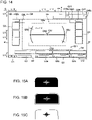
- the graphical user interface G includes a clutch area G1.
- a state of the clutch pedal 22b is displayed in the clutch area G1 as illustrated in FIGS. 15A, 15B, and 15C.
- FIG. 15A illustrates the clutch area in a state (OFF state) in which the clutch pedal 22b is not depressed .
- FIG. 15B illustrates the clutch area in a state (hover state) in which the operator puts his/her foot on the clutch pedal 22b.
- FIG. 15C illustrates the clutch area in a state (ON state) in which the clutch pedal 22b is depressed.
- the graphical user interface G includes a camera area G2 indicating information relating to the endoscope 6.
- the camera area G2 is displayed in an area near the lower end ed (see FIG. 13 ) of the screen gr of the monitor 24.
- the camera area G2 is an example of a "fourth area”.
- the graphical user interface G includes hand areas G3.
- the hand areas G3 display information of the medical instruments 4 attached to the arms 60 and indicate operation states of the medical instruments 4 attached to the arms 60 (and thus may serve as medical instrument operation state indicators).
- the hand areas G3 include: a hand area G3a that displays information about the arm 60a (the arm 60a having the identification number "4") and the medical instrument 4 attached to the arm 60a that is to be operated by the operation handle 21L for the left hand, a hand area G3b that displays information about the arm 60b (the arm 60b having the identification number "3") and the medical instrument 4 for replacement attached to the arm 60b, and a hand area G3c that displays information about the arm 60d (the arm 60d having the identification number "1") and the medical instrument 4 attached to the arm 60d that is to be operated by the operation handle 21R for the right hand.
- the hand areas G3 are displayed in an area in the vicinity of the lower end ed of the screen gr of the monitor 24.
- the clutch area G1 is also displayed in the area in the vicinity of the lower end ed of the screen gr of the monitor 24.
- the clutch area G1, the camera area G2, and the hand area G3 are displayed between the lower end ed of the screen gr and a position above the lower end ed of the screen gr by a length (L11) of one tenth of the vertical length of the screen gr.
- the hand areas G3a, the hand area G3b, and the hand area G3c are examples of a "first area", a "second area”, and a "third area", respectively.
- the information about the arm 60 includes: the identification number (e.g., "1", "2”, etc.) of the arm 60; and an arrow icon that is displayed when the arm 60 is set as a replacement destination of an arm 60 to which the medical instrument 4 for replacement is attached.
- the information about the medical instrument 4 includes a name (a type) of the medical instrument 4.
- the information about the medical instrument 4 also includes the information regarding the operation state of the medical instrument 4, e.g., indication of whether the clutch pedal 22b, the coagulation pedal 22e, the cutting pedal 22d, or the like for the medical instrument 4 is being operated or not.
- the hand areas (hand area G3a and hand area G3c) for the arms 60 that are operation targets to be operated are displayed in dark gray.
- the identification numbers "1" and "4" of the arms 60 that are the operation targets are displayed in white ovals (white elongate circles).
- the hand area (hand area G3b) of the arm 60 that is not the operation target is displayed in light gray, and in this hand area G3b, the identification number "3" of that arm 60 is displayed in an even lighter gray color lighter than the light gray color of the hand area G3b.
- the graphical user interface G includes a medical instrument usage information area G4, which is a pop-up area.
- the medical instrument usage information area G4 the current number of times of use / the maximum number of times of use (see FIG. 16 ) of the medical instrument 4 attached to each arm 60 is displayed in a pop-up.
- the current number of uses of the medical instrument becomes equal to the maximum number of uses of the medical instrument, the current number of uses is displayed in red.
- error information is displayed in a pop-up manner.
- the medical instrument usage information area G4 is displayed in an area adjacent above the clutch area G1, the camera area G2, and the hand area G3 on the monitor 24.
- the medical instrument usage information area G4 is an example of a "surgical instrument usage information area".
- the graphical user interface G includes a level indication area G5.
- the level indication area G5 In the level indication area G5, information on the angle of the endoscope 6 is displayed.
- the level indication area G5 is displayed only while the camera pedal 22c is being depressed (stepped). That is, when receiving the command that enables the movement of the endoscope 6, the image processing device 8 displays a level LV (a level indication LV) of the endoscope 6 in the level indication area G5.
- the level indication area G5 is an example of a "center area”.
- the graphical user interface G includes a left pop-up area G6.
- the icons illustrated in FIGS. 17A to 17C are displayed in the hover state, which is a state where the foot of the operator is placed on the foot pedal 22.
- FIG. 17A illustrates an icon displayed when the foot is placed on the coagulation pedal 22eL or the cutting pedal 22dL.
- FIG. 17B illustrates an icon displayed when the foot is placed on the clutch pedal 22b.
- FIG. 17C illustrates an icon displayed when the foot is placed on the camera pedal 22c.
- the left pop-up area G6 is displayed in a left side portion on the monitor 24.
- the left pop-up area G6 is an example of an "operation pedal area".
- the graphical user interface G includes a right pop-up area G7.
- an icon FIG. 18
- the right pop-up area G7 is displayed in a right side portion on the monitor 24.
- the right pop-up area G7 is an example of an "operation pedal area”.
- the graphical user interface G includes the first area G8 that displays the movable range of the arm 60 and the operable range of the operation handle 21 where the operation handle 21 is operable in the movable range of the arm 60.
- the graphical user interface G also includes a second area G9 that displays a direction in which the operation handle 21 is required to be operated to return the operation handle 21 to the inside of the operable range of the operation handle (toward the center of the operable range of the operation handle) and/or (e.g., "and" in a first embodiment) to return the arm 60 to the inside of the movable range (toward the center of the movable range of the arm 60).
- the number of arms 60 that can be operated by the operation handle 21 is two.
- the operation handle 21L operates the left arm 60L (for example, the arm 60a, see FIG. 1 ) that supports the medical instrument 4
- the operation handle 21R operates the right arm 60R (for example, the arm 60d, see FIG. 1 ) that supports the medical instrument 4.
- the first area G8 includes a first area G8L for the left arm 60L and a first area G8R for the right arm 60R
- the second area G9 includes a second area G9L for the left arm 60L and a second area G9R for the right arm 60R.
- the left arm 60L and the right arm 60R are examples of a "first manipulator" and a "second manipulator.”
- the graphical user interface G includes error notification areas G15 (G15a, G15b)
- the error notification area G15a is displayed in a pop-up to display warning and error information when a warning or an error occurs.
- the error notification area G15b is displayed in a pop-up to display details of notes of the warning and the error displayed in the error notification area G15a.
- the image processing device 8 is configured to switch between a displayable mode and a non-displayable mode, wherein the mark MK1 illustrated in FIG. 13 (also the mark MK2 illustrated in FIG. 25 according to a second embodiment) that corresponds to the medical instrument 4 located outside the field of view of the endoscope 6 is displayable in the displayable mode and is not displayable in the non-displayable mode.
- the mark MK1 illustrated in FIG. 13 also the mark MK2 illustrated in FIG. 25 according to a second embodiment
- the mark MK1 illustrated in FIG. 13 also the mark MK2 illustrated in FIG. 25 according to a second embodiment
- FIG. 19 in response to operation on the touch panel 23 of the remote control apparatus 2, "ON” and “OFF” buttons for turning on and off an "Out-of-view forceps display" are displayed.
- the image processing device 8 displays, in response to the camera pedal 22c being depressed by the operator, the mark MK1 (or the mark MK2 according to a second embodiment) corresponding to the medical instrument 4 that is located outside the field of view of the endoscope 6.
- the mark MK1 or the mark MK2 according to a second embodiment
- the display setting of the "out-of-view forceps display” can be easily switched based on the skill level of the operator's operation and the needs of the operator.
- the graphical user interface G includes a status area G10.
- the status area G10 information such as the remaining amount of the built-in battery of the medical manipulator 1, the brightness / contrast of the monitor 24, the lap time, and the elapsed time of the surgery are displayed.
- the status area G10 is displayed between the upper end eu of the screen gr and a position below the upper end eu of the screen gr by a length (L11) of one tenth of the vertical length of the screen gr.
- the status area G10 is an example of a "surgical system area".
- the image processing device 8 displays, in the monitor 24, the graphical user interface G on the image captured by the endoscope 6 in the overlapped manner, such that the graphical user interface G displays a mark MK1 that indicates the medical instrument 4 that is located outside the field of view of the endoscope 6.
- the mark MK1 (the graphical user interface G) is displayed, when the image processing device 8 receives the command that enables the movement of the endoscope 6 (when the camera pedal 22c is being depressed (stepped) by the operator) and any one of the medical instruments 4 (any one of the medical instruments 4 attached to the arms 60a, 60b, and 60d) is located outside the field of view of the endoscope 6.
- the mark MK1 (the graphical user interface G) is displayed in a neighborhood area G11 in the vicinity of the outer edge of the level indication area G5, wherein the level indication area G5 includes the center portion CN1 of the screen gr of the monitor 24 and does not include the vicinity of the edge e (eu, ed, el, and er) of the monitor screen gr (that is, the level indication area G5 does not include an edge neighborhood portion (or a peripheral portion) of the monitor screen gr inside and in the vicinity of the edge e (eu, ed, el, and er) of the monitor screen gr).
- the neighborhood area G11 is an area located outside the level LV and in the vicinity of the level LV.
- the image processing device 8 acquires the position of the medical instrument 4 based on the posture and the position of the arm 60 to which the medical instrument 4 is attached. Further, the image processing device 8 acquires the imaging direction of the endoscope 6 based on the posture and the position of the arm 60 to which the endoscope 6 is attached. Further, the image processing device 8 acquires the field angle (field of view range) of the endoscope 6 based on the zoom state of the endoscope 6. The image processing device 8 obtains the field angle (field of view range) of the endoscope 6 with reference to values of the mechanical system (lens, etc.) of the endoscope 6.
- the image processing device 8 obtains the coordinates of the distal end of each of the medical instruments 4 with respect to the field of view of the endoscope 6, based on the information on the field of view of the endoscope 6, the posture and the position of the endoscope 6, and the positions of the arms 60. With this, the image processing device 8 determines whether each of the medical instruments 4 is located outside the field of view of the endoscope 6 or not.
- the medical instruments 4 (the medical instruments 4 such as the forceps 4b other than the endoscope 6) are respectively attached to the arm 60a (corresponding to the hand area G3a having the identification number "4"), the arm 60b (corresponding to the hand area G3b having the identification number "3"), the arm 60d (corresponding to the hand area G3c having the identification number "1") among the arms 60a, 60b, 60c, and 60d.
- the endoscope 6 is attached to the arm 60c (corresponding to the camera area G2 having the identification number "2").
- the arm 60a (corresponding to the hand area G3a having the identification number "4") and the arm 60d (corresponding to the hand area G3c having the identification number "1") are in the active states in which the arm 60a and 60d are allowed to be operated by the operation handle(s) 21, and the hand areas G3a and G3c corresponding to these arms 60a and 60d are displayed in dark gray.
- the arm 60b is in the inactive state in which the arm 60b is not allowed to be operated by the operation handle(s) 21, and the hand area G3b corresponding the arm 60b is displayed in light gray.
- the medical instrument 4 attached to the arm 60a (corresponding to the hand area G3a having the identification number "4") and the medical instrument 4 attached to the arm 60d (corresponding to the hand area G3c having the identification number "1") are located in the field of view of the endoscope 6.
- the medical instrument 4 attached to the arm 60b (corresponding to the hand area G3b having the identification number "3" ) is located outside the field of view of the endoscope 6.
- the graphical interface G is configured to display the mark MK1 that indicates the medical instrument 4 that is located outside the field of view of the endoscope 6, at the area G12 (see FIG. 20 ), in the neighborhood area G11, that is deviated from the center CN2 of the level indication area G5 in the direction in which the medical instrument 4 is deviated from the field of view of the endoscope 6.
- the mark MK1 (the letter of the number "3") is displayed.
- the area G12 that displays the mark MK1 indicating (corresponding to) the medical instrument 4 that is located outside the field of view of the endoscope 6 is one of the areas G12 into which the neighborhood area G11 is divided by radially extending lines centered on the center CN2 of the level indication area G5.
- the neighborhood area G11 is radially divided into eight areas G12a to G12h by the radial lines radially extending from the center CN2 of the level indication area G5.
- the eight areas G12a to G12h are arranged at intervals of 45 degrees about the center CN2.
- FIG. 20 illustrates all of display patterns, in which a pair of the marks MK1 having the identification numbers "1” and "4", which indicates the medical instruments 4 corresponding to the identification numbers "1” and "4" are located outside the field of view of the endoscope 6, is displayed in each one of the areas G12a, G12b, G12, G12d, G12e, G12f, G12g, and G12h.
- the image processing device 8 when receiving the command that enables the movement of the endoscope 6, the image processing device 8 displays the level LV of the endoscope 6 in the level indication area G5.
- the image processing device 8 displays, on the monitor 24, the graphical user interface G to display the mark MK1 in the neighborhood area G11 in the vicinity of the outer edge of the level indication area G5.
- the level LV indicates the inclination of the field of view of the endoscope 6 with respect to the patient P.
- the level LV is displayed when the image processing device 8 receives the command that enables the movement of the endoscope 6 (when the camera pedal 22c is operated, e.g., is depressed).
- the level indication area G5 is a rectangular area (a rectangular shape elongated in the lateral direction) including the upper side G5a, the left side G5b, the right side G5c, and the lower side G5d thereof.
- the visibility of the operator can be improved by displaying the mark MK1 in the neighborhood area G11 in the vicinity of the level indication area G5 having a predetermined size including the center portion of the screen gr.
- the upper side G5a of the level indication area G5 is provided between a position upper from the center CN1 of the screen gr of the monitor 24 by the length L11 of one tenth of the vertical length of the screen gr and a position lower from the upper edge eu of the screen gr by the length L11 of one tenth of the vertical length of the screen gr. It may be preferable that the upper side G5a of the level indication area G5 is provided between a position upper from the center CN1 of the screen gr by a length of one eighth of the vertical length of the screen gr and a position lower from the upper edge eu of the screen by the length of one eighth of the vertical length of the screen gr.
- the upper side G5a of the level indication area G5 is provided between a position upper from the center CN1 of the screen gr by a length of one sixth of the vertical length of the screen gr and a position lower from the upper edge eu of the screen by the length of one sixth of the vertical length of the screen gr.
- the upper side G5a of the level indication area G5 is provided a position lower than the status area G10 that displays the remaining battery level of the built-in battery of the medical manipulator 1, or the like.
- the left side G5b of the level indication area G5 is provided between a position left from the center CN1 of the screen gr of the monitor 24 by the length L12 of one tenth of the horizontal length of the screen gr, and a position right from the left end el of the screen gr by the length L12. It may be preferable that the left side G5b of the level indication area G5 is provided between a position left from the center CN1 of the screen gr of the monitor 24 by a length of one eighth of the horizontal length of the screen gr and a position right from the left end el of the screen gr by the length of one eighth of the horizontal length of the screen gr.
- the left side G5b of the level indication area G5 is provided between a position left from the center CN1 of the screen gr of the monitor 24 by a length of one sixth of the horizontal length of the screen gr and a position right from the left end el of the screen gr by the length of one sixth of the horizontal length of the screen gr.
- the right side G5c of the level indication area G5 is provided between a position right from the center CN1 of the screen gr of the monitor 24 by the length L12 of one tenth of the horizontal length of the screen gr and a position left from the right end er of the screen gr by the length L12 of one tenth of the horizontal length of the screen gr. It may be preferable that the right side G5c of the level indication area G5 is provided between a position right from the center CN1 of the screen gr of the monitor 24 by a length of one eighth of the horizontal length of the screen gr and a position left from the right end er of the screen gr by the length of one eight of the horizontal length of the screen gr.
- the right side G5c of the level indication area G5 is provided between a position right from the center CN1 of the screen gr of the monitor 24 by a length of one sixth of the horizontal length of the screen gr and a position left from the right end er of the screen gr by the length of one sixth of the horizontal length of the screen gr.
- the lower side G5d of the level indication area G5 is provided between a position lower from the center CN1 of the screen gr of the monitor 24 by the length L11 of one tenth of the vertical length of the screen gr and a position upper from the lower end ed of the screen by the length L11 of one tenth of the vertical length of the screen gr. It may be preferable that the lower side G5d of the level indication area G5 is provided between a position lower from the center CN1 of the screen gr of the monitor 24 by a length of one eighth of the vertical length of the screen gr and a position upper from the lower end ed of the screen by the length of one eighth of the vertical length of the screen gr.
- the lower side G5d of the level indication area G5 is provided between a position lower from the center CN1 of the screen gr of the monitor 24 by a length of one sixth of the vertical length of the screen gr and a position upper from the lower end ed of the screen by the length of one sixth of the vertical length of the screen gr.
- the lower end G5d of the level indication area G5 is provided above the hand area G3a, the hand area G3b, the hand area G3c, and the camera area G2. Further, the lower end G5d of the level indication area G5 is provided above the medical instrument usage information area G4.
- center CN1 of the screen gr of the monitor 24 and the center CN2 of the level indication area G5 are provided at positions substantially same as each other.
- the mark MK1 indicating the medical instrument 4 that is located outside the field of view is displayed in an area between the level indication area G5 and at least one (e.g., "all" in a first embodiment) of the medical instrument usage information area G4, the left pop-up area G6, the right pop-up area G7, and the status area G10.
- the medical instrument usage information area G4 indicates the usage information of each medical instrument 4.
- the left pop-up area G6 is displayed when the foot pedal 22 is operated (that is, in the hover state where the foot is placed on the foot pedal 22).
- the right pop-up area G7 is displayed when the coagulation pedal 22eR or the cutting pedal 22dR is operated (that is, when the foot is placed on the coagulation pedal 22eR or the cutting pedal 22dR).
- the status area G10 displays the status of the surgical system 400.
- the mark MK1 includes the identification number to identify the arm 60 that supports the medical instrument 4 that is located outside the field of view of the endoscope 6.
- the letter of the number "3" serving as the mark MK1 is displayed indicating that the medical instrument 4 attached to the arm 60b (corresponding to the hand area G3a having the identification number "3") is located outside the field of view of the endoscope 6.
- the mark MK1 is displayed in different manners depending on whether the medical instrument 4 located outside the field of view is an operation target or not. Specifically, as illustrated in FIG. 21 , when the medical instrument 4 attached to the arm 60 is an operation target, the mark MK1 is displayed, which is the black-colored identification number (any of 1 to 4) of the arm 60 in a white oval in a black square. To the contrary, as illustrated in FIG. 22 , when the medical instrument 4 attached to the arm 60 is not an operation target, the mark MK1 is displayed, which is the gray-colored identification number (any of 1 to 4) of the arm 60 in a black square.
- FIG. 20 when two or more of the medical instruments 4 among the medical instrument 4 attached to the arm 60a, the medical instrument 4 attached to the arm 60b, and the medical instrument 4 attached to the arm 60d are located outside the field of view of the endoscope 6, two or more of the marks MK1 corresponding to the medical instruments 4 that are located outside the field of view of the endoscope 6 are displayed so as to correspond to the order of the arrangement positions of the arm 60a, the arm 60b, and the arm 60d.
- the order of the arrangement positions of the arm 60a, the arm 60b, and the arm 60d means the order of the positions of the arm 60a, the arm 60b, and the arm 60d in the state where the arm 60a, the arm 60b, and the arm 60d are attached to the arm base 50.
- the mark MK1 having the identification number "4" corresponding to the arm 60a, the mark MK1 having the identification number "3" corresponding to the arm 60b, and the mark MK1 having the identification number "1" corresponding to the arm 60d are displayed in that order so as to corresponding to the order of the arrangement positions of the arms 60a, 60b, and 60d.
- the mark MK1 having the identification number "4", the mark MK1 having the identification number "3", and the mark MK1 having the identification number "1" are displayed in the arrangement order of the hand area G3a having identification number "4", the hand area G3b having identification number "3", and the hand area G3c having identification number "1".
- the mark(s) MK1 corresponding the one or two medical instruments 4 located outside the field of view of the endoscope 6 are displayed at the positions shifted toward the center of the screen gr of the monitor 24 than those in the state where all the marks MK1 are displayed.
- the mark MK1 having the identification number "4" corresponding to the medical instrument 4 attached to the arm 60a is displayed so as to be arranged closer to (shifted toward) the center of the screen gr than a position of the mark MK1 having identification number "4" in the state where all the three marks MK1 having identification numbers "4" , "3", and "1" are displayed (see FIG. 20 ).
- the mark MK1 having the identification number "4" corresponding to the medical instrument 4 attached to the arm 60a is displayed so as to be arranged closer to the center of the screen gr than a position of the mark MK1 having identification number "4" in the state where all the three marks MK1 having identification numbers "4" , "3", and "1" are displayed (see FIG. 20 ).
- the mark MK1 having the identification number "1" corresponding to the medical instrument 4 attached to the arm 60d is displayed so as to be arranged closer to the center of the screen gr than a position of the mark MK1 having identification number "1" in the state where all the three marks MK1 having identification numbers "4" , "3", and "1" are displayed (see FIG. 20 ).
- step S1 the image processing device 8 acquires the image captured by the endoscope 6 configured to acquire the image of the surgical site.
- step S2 the image processing device 8 determines whether the command that enables the endoscope 6 to move is received (whether the camera pedal 22c is depressed by the operator). In the case of "Yes” in step S2, the process proceeds to step S3. In the case of "No” in step S2, the process returns to step S1.
- step S3 the image processing device 8 determines whether at least one (any one) of the medical instruments 4 attached to the arms 60a, 60b, and 60d is located outside the field of view of the endoscope 6.
- step S3 that is, in the case where the command that enables the movements of the endoscope 6 is received and at least one of the medical instruments 4 that are attached to the arms 60 is located outside the field of view of the endoscope 6
- the process proceeds to step S4.
- step S4 the process returns to step S1.
- step S4 the image processing device 8 displays, on the screen gr of the monitor 24, the graphical user interface G on the image captured by the endoscope 6 in the overlapped manner, such that the graphical user interface G displays, at the neighborhood area G11 in the vicinity of the outer edge of the level indication area G5, the mark MK1 indicating the medical instrument 4 that is located outside the field of view of the endoscope 6, wherein the level indication area G5 includes the center CN1 of the monitor screen gr and does not include the vicinity of the edge e of the monitor screen gr.
- steps S1 to S4 described above are always performed during the operation of the surgical operation system 100.
- the image processing device 8 displays, on the screen gr of the monitor 24, the graphical user interface G on the image captured by the endoscope 6 in the overlapped manner, such that the graphical user interface G displays, in the neighborhood area G11 in the vicinity of the outer edge of the level indication area G5, the mark MK1 indicating the medical instrument that is located outside the field of view of the endoscope 6, wherein the level indication area G5 is displayed at the central region of the monitor screen gr and includes the center CN1 of the monitor screen gr and does not include the vicinity of the edge e (eu, ed, el, and er) of the monitor screen gr.
- the mark MK1 indicating the medical instrument 4 that is located outside the field of view of the endoscope 6 is displayed at the position closer to the center of the screen gr of the monitor 24 than the vicinity of the edge e of the monitor screen gr is.
- the operator can easily visually recognize the mark MK1 indicating the medical instrument 4 that is located outside the field of view of the endoscope 6 without significantly moving the line of sight.
- the graphical interface G is configured to display the mark MK1 indicating the medical instrument 4 that is located outside the field of view of the endoscope 6, in one of the areas G12, in the neighborhood area G11 in the vicinity of the outer edge of the level indication area G5, that is deviated from the center CN2 of the level indication area G5 in the direction in which the medical instrument 4 is deviated from the field of view of the endoscope 6.
- the mark MK1 is located in the vicinity of the level indication area G5 and displaced from the center CN2 of the level indication area G5 in the direction in which the medical instrument 4 is displaced from the field of view of the endoscope 6.
- the operator can easily recognize the displaced direction in which the medical instrument 4 outside the field of view of the endoscope 6 is displaced from the field of view of the endoscope 6 without significantly moving the line of sight from the level indication area G5. Further, since the position of the mark MK1 relative to the center CN2 of the level indication area G5 in the screen gr of the monitor 24 corresponds to the position of the medical instrument 4 that is located outside the field of view of the endoscope 6 relative to the field of view of the endoscope 6, the operator can intuitively and easily recognize the position (the displaced direction) of the medical instrument 4 located outside the field of view of the endoscope 6.
- the area G12 that displays the mark MK1 indicating the medical instrument 4 located outside the field of view of the endoscope 6 is one of the areas G12 (G12a to G12h) into which the neighborhood area G11 is divided by lines radially extending from the center CN2 of the level indication area G5.
- the plural areas G12 are radially arranged from the center CN2 of the level indication area G5 (that is, the plural areas G12 are circumferentially arranged around the center CN2 of the level indication area G5), the position of the medical instrument 4 located outside the field of view can be more intuitively recognized, unlike a case where the plural areas G12 are provided in only one region in the screen gr of the monitor 24.
- the image processing device 8 when receiving the command that enables the movement of the endoscope 6, displays, on the monitor 24, the level LV of the endoscope 6 in the level indication area G5 and the graphical user interface G that displays the mark MK1 outside the level LV.
- the mark MK1 indicating the medical instrument 4 located outside the field of view is displayed together with the level LV. Accordingly, the operator can more easily recognize the mark MK1.
- the mark MK1 indicating the medical instrument 4 that is located outside the field of view is displayed in an area between the level indication area G5 and at least one of the medical instrument usage information area G4, the left pop-up area G6, the right pop-up area G7, and the status area G10.
- the mark MK1 is displayed closer to the center of the screen than the at least one of the medical instrument usage information area G4, the left pop-up area G6, the right pop-up area G7, and the status area G10. Therefore, unlike the case where the mark MK1 is arranged at the edge portion e of the screen gr, the visibility of the mark MK1 can be improved.
- the level indication area G5 has the rectangular shape having the upper side G5a, the left side G5b, the right side G5c, and the lower side G5d thereof, in such a manner that the upper side G5a of the rectangular level indication area G5 is located closer to the upper end eu of the screen gr of the monitor 24 than the center CN1 of the screen gr of the monitor 24 is, the left side G5b of the rectangular level indication area G5 is located closer to the left end el of the screen gr than the center CN1 of the screen gr is, the right side G5c of the rectangular level indication area G5 is located closer to the right end er of the screen gr than the center CN1 of the screen gr is, and the lower side G5d of the rectangular level indication area G5 is located closer to the lower end ed of the screen gr than the center CN1 of the screen gr is.
- the mark MK1 is displayed in the neighborhood area G11 in the vicinity of the outer edge of the level indication area G5, so that the mark MK1 is not displayed in the center portion of the screen gr of the monitor 24. Therefore, it is possible to prevent the mark MK1 from hindering the operator from visually recognizing the center portion of the screen gr of the monitor 24.
- the upper side G5a of the level indication area G5 is provided between a position upper from the center CN1 of the screen gr of the monitor 24 by the length L11, which is one tenth of the vertical length of the screen gr, and a position lower from the upper edge eu of the screen gr by the length L11.
- the left side G5b of the level indication area G5 is provided between a position left from the center CN1 of the screen gr of the monitor 24 by the length L12, which is one tenth of the horizontal length of the screen gr, and a position right from the left end el of the screen gr by the length L12.
- the right side G5c of the level indication area G5 is provided between a position right from the center CN1 of the screen gr of the monitor 24 by the length L12, which is one tenth of the horizontal length of the screen gr, and a position left from the right end er of the screen gr by the length L12.
- the lower side G5d of the level indication area G5 is provided between a position lower from the center CN1 of the screen gr of the monitor 24 by the length L11, which is one tenth of the vertical length of the screen gr, and a position upper from the lower end ed of the screen by the length L11.
- the mark MK1 displayed in the neighborhood area G11 in the vicinity of the outer edge of the level indication area G5 is located closer to the center of the screen gr from the edge portion e of the screen gr. Therefore, unlike the case where the mark MK1 is arranged at the edge portion e of the screen gr, the visibility of the mark MK1 can be improved.
- the upper side G5a of the level indication area G5 is provided between a position upper from the center CN1 of the screen gr of the monitor 24 by a length of one eighth of the vertical length of the screen gr and a position lower from the upper edge eu of the screen gr by the length of one eighth of the vertical length of the screen gr
- the left side G5b of the level indication area G5 is provided between a position left from the center CN1 of the screen gr of the monitor 24 by a length of one eighth of the horizontal length of the screen gr and a position right from the left end el of the screen gr by the length of one eighth of the horizontal length of the screen gr
- the right side G5c of the level indication area G5 is provided between a position right from the center CN1 of the screen gr of the monitor 24 by the length of one eighth of the horizontal length of the screen gr and a position left from the right end er of the screen gr
- the plurality of arms 60 includes the arm 60b that supports the medical instrument 4 for replacement that is not an operation target, and the graphical user interface G displays, at an edge neighborhood area in the vicinity of the lower end ed of the screen gr of the monitor 24, the hand area G3a that indicates the information regarding the medical instrument 4 supported by the arm 60d, the hand area G3b that indicates the information regarding the medical instrument 4 supported by the arm 60b, the hand area G3c that indicates the information regarding the medical instrument 4 supported by the arm 60a, and the camera area G2 that indicates the information regarding the endoscope 6.
- the mark MK1 is displayed closer to the center of the screen gr than the hand areas G3a, G3b, and G3c and the camera area G2 are.
- the visibility of the mark MK1 can be further improved.
- the level indication area G5 is the rectangular area having the upper side G5a, the left side G5b, the right side G5c, and the lower side G5d thereof and the lower side G5d of the level indication area G5 is located upper than the hand areas G3a, G3b, and G3c and the camera area G2.
- the mark MK1 is located at a position upper than that in a case where the lower end G5d of the level indication area G5 is provided at the lower end ed of the screen gr. Therefore, the mark MK1 can be visually recognized while suppressing the downward movement of the line of sight of the operator.
- the marks MK1 corresponding to the two or more of the medical instruments 4 located outside the field of view of the endoscope 6 are displayed so as to be arranged in the order corresponding to the arrangement order of the arms 60a, 60b and 60d to which the two of more of the medical instruments 4 are attached.
- the operator O can easily recognize the arrangement order of the medical instruments 4 that are located outside the field of view of the endoscope 6.
- the image processing device 8 is configured to switch between the displayable mode in which the marks MK1 are displayable and the non-displayable mode in which the marks MK1 are not displayable. As a result, it is possible to switch between the displayable mode in which the marks MK1 are displayable and the non-displayable mode in which marks MK2 are not displayable, as needed.
- the marks MK1 corresponding to all the medical instruments 4 are displayed in the order of the arrangement positions of the arms 60 that supports all the medical instruments 4.
- one or two of the marks MK1 corresponding to the one or two of the medical instruments 4 are displayed at the positions closer to the center of the screen g than those in the state where all the marks MK1 are displayed.
- the remote control apparatus 2 includes the camera pedal 22c for inputting the command that enables the endoscope 6 to move, and the endoscope 6 is configured to be moved according to both of the operation handle 21R and operation handle 21L being moved together while the camera pedal 22c is being depressed to output the command that enables the endoscope 6 to move.
- the operator O can easily move the endoscope 6 by operating the camera pedal 22c.
- the mark MK1 is displayed in different manners depending on whether the medical instrument 4 located outside the field of view is an operation target or not.
- the operator O can easily recognize whether or not the medical instrument 4 that is located outside the field of view of the endoscope 6 is an operation target.
- the mark MK1 includes the number that identifies the arm 60 that supports the medical instrument 4 that is located outside the field of view of the endoscope 6. With this configuration, the operator O can easily identify the medical instrument 4 that is located outside the field of view of the endoscope 6.
- a mark MK2 includes an arrow MK2a that indicates a direction in which the medical instrument 4 that is located outside the field of view of the endoscope 6 is deviated from the field of view of the endoscope 6.
- the identification number (for example, "4") of the medical instrument 4 that is located outside the field of view of the endoscope 6 is displayed at a position in the vicinity of the arrow MK2a and on the outer side of the arrow MK2a. Note that the identification number may be displayed in the arrow MK2a, like a mark MK3 such as being illustrated in FIG. 27 .
- the inside of the arrow MK2a is displayed as transparent or translucent so that the image captured by the endoscope can be seen through the arrow MK2a.
- the identification number in the mark MK2 corresponding to the target medical instrument 4 is displayed in black color in a white circle (see the number "4" in FIGS. 25 ).
- the identification number in the mark MK2 corresponding to the non-target medical instrument 4 is displayed in gray color in a black circle (see the identification number "3" in FIG. 26 ).
- the arrow MK2a is two-dimensionally displayed.
- the mark MK2 includes the arrow MK2a that indicates the direction in which the medical instrument 4 that is located outside the field of view of the endoscope 6 is deviated from the field of view of the endoscope 6.
- the image processing device 8 acquires the image from the endoscope 6 and generates the graphical user interface G.
- the control unit 31 of the medical manipulator 1, a control unit (not illustrated) of the remote control apparatus 2, or the like may generate the graphical user interface G.
- an image processing device that acquires the image from the endoscope 6 and an image processing device that generates a graphical user interface G to be superimposed on the image acquired from the endoscope 6 may be separately provided.
- the mark MK1 is displayed in one of the areas G12 that is deviated from the center CN2 of the level indication area G5 in the direction in which the medical instrument 4 is deviated from the field of view of the endoscope 6.
- the invention is not limited thereto.
- the mark MK2 may be displayed at a fixed position in the neighborhood area G11 in the vicinity of the outer edge of the level indication area G5.
- the invention is not limited thereto.
- the number of the divided areas G12 may be a number other than eight.
- the mark MK1 is displayed outside the level indication area G5.
- the invention is not limited thereto.
- the mark MK1 may be displayed in the level indication area G5.
- the level indication area G5 has the rectangular shape.
- the invention is not limited thereto.
- the level indication area G5 may have a shape other than the rectangular shape (e.g., an oval shape or the like).
- the camera area G2 and the hand areas G3 (the hand area G3a, the hand area G3b, and the hand area G3c) are displayed in the area in the vicinity of the lower end of the screen gr of the monitor 24.
- the invention is not limited thereto.
- the camera area G2 and the hand areas G3 (the hand area G3a, the hand area G3b, and the hand area G3c) may be displayed in an area in the vicinity of the upper end eu of the screen gr of the monitor 24.
- the camera area G2 and the hand areas G3 may be displayed between the upper end eu of the screen gr and a position blow the upper end eu of the screen gr by the length (L11) of one tenth of the vertical length of the screen gr.
- first and second embodiments described above the case has been described in which, when two or more of the medical instruments 4 are located outside the field of view of the endoscope 6, two or more marks MK1 corresponding to the two or more of the medical instruments 4 are displayed in the arrangement order of the arms 60 that supports the two or more of the medical instruments 4.
- the invention is not limited thereto.
- the order of the positions of the marks MK1 displayed may be different from the order of the physical positions of the arms 60 that support the medical instruments 4.
- first and second embodiments described above the case has been described in which, when one or two of the medical instruments 4 are located outside the field of view of the endoscope 6, the one or two marks MK1 corresponding to the one or two of the medical instruments 4 are displayed at the position shifted toward the center of the screen g.
- the invention is not limited thereto.
- a position of each of the marks MK1 corresponding to the medical instruments 4 may be fixed.
- the mark MK1 is displayed in different manners depending on whether the medical instrument 4 located outside the field of view is an operation target or not.
- the invention is not limited thereto.
- the mark MK1 may be displayed in the same manner regardless of whether the medical instrument 4 located outside the field of view is an operation target or not.
- a portion (e.g. a left end portion) of each of the hand areas G3a, G3b and G3c may include divided eight sections G13 (see FIG. 29A ), and one of the eight sections G13 may be highlighted in a color (e.g., white) different from the rest of the eight sections G13 (see FIG. 29B ), to indicate the position of the medical instrument 4 that is located outside the field of view of the endoscope 6.
- the mark MK1 indicating the medical instrument 4 that is located outside the field of view of the endoscope 6 is displayed in the neighborhood area G1 in the vicinity of the outer edge of the level indication area G5.
- the invention is not limited thereto.
- an outer circumferential portion of each of the hand areas G3a, G3b, and G3c may be divided into eight sections G14, and one of the eight sections G14 may be highlighted in a color (e.g., white) different from the rest of the eight sections G14, to indicate the position of the medical instrument 4 that is located outside the field of view of the endoscope 6.
- the number of the arms 60 provided is four.
- the invention is not limited thereto.
- the number of the arms 60 may be any number as long as at least one is provided.
- each of the arm portion 61 and the positioner 40 are configured as the 7-axis articulated robot.
- the invention is not limited thereto.
- each of the arm portion 61 and the positioner 40 may be configured as an articulated robot other than the 7-axis articulated robot (for example, a 6-axis articulated robot, an 8-axis articulated robot, or the like).
- the medical manipulator 1 includes the medical trolley 3, the positioner 40, and the arm base 50.
- the invention is not limited thereto.
- the medical manipulator 1 may include only the arms 60 and not include the medical trolley 3, the positioner 40, or the arm base 50.
- a mark MK4 such as being illustrated in FIG. 32 may include the outer edge e1 of the black squire surrounded by another color (such as, red, or the like).
- a mark MK5 such as being illustrated in FIG. 33A may be displayed having the identification number of the arm 60 in the white oval without the black square (e.g., when the medical instrument 4 is an operation target), or a mark MK5 such as being illustrated in FIG. 33B may be displayed having the gray-colored identification number of the arm 60 without the black squire and the white oval (e.g., when the medical instrument is a non-operation target).
- the arrow MK2a is two-dimensionally displayed.
- the invention is not limited thereto.
- the arrow MK2a may be three-dimensionally displayed.
- the level indication area G5 in which the level LV is displayed serves as a center area according to the invention.
- the invention is not limited thereto.
- an area other than the level indication area G5 may serve as the center area.
- each of the elements disclosed herein may be carried out by a circuit or a processing circuit including a general purpose processor, a dedicated processor, an integrated circuit, an ASIC (Application Special Integrated Circuit), a conventional circuit, or a combination of two or more of them, that is configured or programmed to perform the functions.
- a processor is considered a processing circuit or a circuit because it contains transistors and other circuit elements.
- a circuit, a unit, or a means may be either a hardware that is configured to perform the recited function(s) or a hardware that is programmed to perform the recited function(s).
- the hardware may be the hardware disclosed herein, or may be other known hardware that is programmed or configured to perform the function(s) described. If the hardware is a processor which is considered as a type of a circuit, a circuit, a means, or a unit is a combination of hardware and software, and the software is used to configure the hardware and/or the processor.
Abstract
Description
- The disclosure may relate to a surgical system and a display method, and more particularly to a surgical system and a display method to display, in a display device, a graphical user interface on an image captured by an endoscope in an overlapped manner.
- In a related art, there is known a robotic surgical system that superimposes and displays a graphical user interface on an image captured by an endoscope (see, for example, Patent Document 1).
- In the robotic surgical system disclosed in
Patent Document 1, the endoscope captures an image of a surgical site, in order to display the captured image in a viewing area (image display area) of a monitor screen. In the robotic surgical system, a current position of a surgical tool is determined relative to the image (the field of view) captured by the endoscope. Then, when the determined current position of the surgical tool is located outside the image (the field of view), a symbol indicating the current position of the surgical tool is displayed at a boundary area outside the viewing area of the monitor screen. - Patent Document 1:
Japanese Patent Application Publication No. 2013-188574 - However, in such a robotic surgical system disclosed in
Patent Document 1, an operator may concentrate on the center region of the viewing area of the monitor screen during surgery. Accordingly, even if the current position of the tool (the surgical instrument) that is located outside the field of view is displayed as the symbol (mark) in the boundary area outside the viewing area of the monitor screen, the operator may not notice the symbol. When the operator notices the symbol, the operator may need to significantly move the line of sight. - An object of one or more embodiments of the disclosure may be to provide a surgical system and a display method that allows an operator to visually recognize a mark indicating a surgical instrument that is located outside the field of view easily without significantly moving the line of sight.
- A first aspect of one or more embodiments may be a surgical system that may include: manipulators that respectively support an endoscope and surgical instruments; a remote control apparatus that includes a display device configured to display an image captured by the endoscope and operation handles configured to operate the surgical instruments, respectively; and a control device configured to generate a graphical user interface and display, on the display device, the graphical user interface on the image captured by the endoscope in an overlapped manner. The control device is configured to display, in response to receiving a command that enables the endoscope to move and determining that at least one of the surgical instruments is located outside a field of view of the endoscope, a mark that corresponds to the surgical instrument that is located outside the field of view of the endoscope at a neighborhood area in a vicinity of an outer edge of a center area of the graphical user interface. The center area does not include a vicinity of an edge of a screen of the display device and includes a center of the screen of the display device.
- According to the first aspect described above, the control device displays, in the screen of the display device, the graphical user interface on the image captured by the endoscope in the overlapped manner, such that the graphical user interface displays the mark indicating the at least one of the first surgical instrument and the second surgical instrument that is located outside the field of view of the endoscope at the neighborhood area in the vicinity of the outer edge of the center area of the screen of the display device, wherein the center area includes the center of the screen and does not include the vicinity of the edge of the screen. Accordingly, the mark indicating the at least one of the first surgical instrument and the second surgical instrument that is located outside the field of view is displayed at a position relatively closer to the center of the screen than the vicinity of the edge of the screen of the display device is. As a result, an operator can easily visually recognize the mark indicating the surgical instrument that is located outside the field of view without significantly moving the line of sight.
- A second aspect of one or more embodiments may be a surgical system that may include: manipulators that support an endoscope and surgical instruments, respectively; a remote control apparatus that includes a display device configured to display an image captured by the endoscope, a first operation handle to operate a first surgical instrument among the surgical instruments, a second operation handle to operate a second surgical instrument among the surgical instruments, and an endoscope pedal configured, when being operated, to enable the endoscope to move according to operation of both of the first operation handle and the second operation handle together; and a control device configured to generate a graphical user interface and display, on the display device, the graphical user interface on the image captured by the endoscope in an overlapped manner. The control device is configured to display, in response to determining that the endoscope pedal is operated and that at least one of the surgical instruments is located outside a field of view of the endoscope, a mark that corresponds to the surgical instrument that is located outside the field of view of the endoscope at a neighborhood area in a vicinity of an outer edge of a center area of the graphical user interface. The center area does not include a vicinity of an edge of a screen of the display device and includes a center of the screen of the display device.
- According to the second aspect described above, the control device displays, in the screen of the display device, the graphical user interface on the image captured by the endoscope in the overlapped manner, such that the graphical user interface displays the mark indicating the at least one of the first surgical instrument and the second surgical instrument that is located outside the field of view of the endoscope in the neighborhood area in the vicinity of the outer edge of the center area of the screen of the display device, wherein the center area includes the center of the screen and does not include the vicinity of the edge of the screen. Accordingly, the mark indicating the at least one of the first surgical instrument and the second surgical instrument that is located outside the field of view is displayed at a position relatively closer to the center of the screen than the vicinity of the edge of the screen of the display device is. As a result, the second aspect can provide the surgical system that allows an operator to visually recognize the mark indicating the surgical instrument that is located outside the field of view of the endoscope easily, without significantly moving the line of sight.
- A third aspect of one or more embodiments may be a display method that may include: acquiring an image at a surgical site captured by an endoscope; generating a graphical user interface and displaying, on a display device, the graphical user interface on the image captured by the endoscope in an overlapped manner; and in response to receiving a command that enables the endoscope to move and determining that at least one of a first surgical instrument that is supported by a first manipulator and a second surgical instrument that is supported by a second manipulator is located outside a field of view of the endoscope, displaying a mark indicating the at least one of the first surgical instrument and the second surgical instrument that is located outside the field of view of the endoscope at a neighborhood area in a vicinity of an outer edge of a center area of the graphical user interface. The center area of the graphical user interface does not include a vicinity of an edge of a screen of the display device and includes a center of the screen of the display device.
- According to the third aspect described above, the displaying of the graphical user interface includes displaying, in the screen of the display device, the graphical user interface on the image captured by the endoscope in the overlapped manner, such that the graphical user interface displays the mark indicating the at least one of the first surgical instrument and the second surgical instrument that is located outside the field of view of the endoscope in the neighborhood area in the vicinity of the outer edge of the center area of the screen of the display device, wherein the center area includes the center of the screen and does not include the vicinity of the edge of the screen. Accordingly, the mark indicating the at least one of the first surgical instrument and the second surgical instrument that is located outside the field of view is displayed at a position relatively closer to the center of the screen than the vicinity of the edge of the screen is. As a result, the third aspect can provide a display method capable of allowing an operator to visually recognize the mark indicating the surgical instrument that is located outside the field of view of the endoscope easily, without significantly moving the line of sight.
- According to an embodiment of the disclosure, an operator can easily visually recognize a mark indicating a surgical instrument that is located outside a field of view, without significantly moving a line of sight.
-
-
FIG. 1 is a diagram illustrating a view of a configuration of a surgical operation system according to a first embodiment; -
FIG. 2 is a diagram illustrating a view of a configuration of a medical manipulator according to a first embodiment; -
FIG. 3 is a diagram illustrating a view of a configuration of an operation handle according to a first embodiment; -
FIG. 4 is a diagram illustrating a view of foot pedals according to a first embodiment; -
FIG. 5 is a diagram illustrating a view of a configuration of an arm of the medical manipulator according to a first embodiment; -
FIG. 6 is a diagram illustrating a view of forceps; -
FIG. 7 is a diagram illustrating a perspective view of a configuration of an operation unit of the medical manipulator according to a first embodiment; -
FIG. 8 is a diagram illustrating a view of an endoscope; -
FIG. 9 is a diagram illustrating a view of a pivot position setting device; -
FIG. 10 is a diagram illustrating a view for explaining translational movements of the arm; -
FIG. 11 is a diagram illustrating a view for explaining rotational movements of the arm; -
FIG. 12 is a block diagram of a configuration of a control unit of the medical manipulator according to a first embodiment; -
FIG. 13 is a diagram illustrating an image captured by the endoscope and a graphical user interface; -
FIG. 14 is a diagram illustrating a view of the graphical user interface including a plurality of areas; -
FIGS. 15A, 15B, and 15C are diagrams for explaining display states of a clutch area; -
FIG. 16 is a diagram for explaining a display state of a medical equipment usage information area; -
FIGS. 17A, 17B, and 17C are diagrams for explaining a left pop-up area; -
FIG. 18 is a diagram for explaining a right pop-up area; -
FIG. 19 is a diagram for explaining a display state of a touch panel of a remote control apparatus; -
FIG. 20 is a diagram for explaining examples of marks according to a first embodiment; -
FIG. 21 is a diagram for explaining an example of a mark (for an operation target) according to a first embodiment; -
FIG. 22 is a diagram for explaining an example of a mark (for a non-operation target) according to a first embodiment; -
FIG. 23 is a diagram for explaining examples of marks displayed so as to be shifted toward a center according to a first embodiment; -
FIG. 24 is a flowchart for explaining a display method according to a first embodiment; -
FIG. 25 is a diagram for explaining a graphical user interface including a mark on an image captured by an endoscope according to a second embodiment; -
FIG. 26 is a diagram for explaining examples of marks according to a second embodiment; -
FIG. 27 is a diagram for explaining an example of a mark according to a second embodiment; -
FIG. 28 is a diagram for explaining a graphical user interface including a mark on an image captured by an endoscope according to a first modification; -
FIGS. 29A and 29B are diagrams for explaining examples of marks according to a first modification; -
FIG. 30 is a diagram for explaining a graphical user interface including a mark on an image captured by an endoscope according to a second modification; -
FIG. 31 is a diagram for explaining examples of marks according to a second modification; -
FIG. 32 is a diagram for explaining an example of a mark according to a third modification; and -
FIGS. 33A and 33B are diagrams for explaining examples of marks according to a fourth modification. - Descriptions are provided hereinbelow for one or more embodiments based on the drawings. In the respective drawings referenced herein, the same constituents are designated by the same reference numerals and duplicate explanation concerning the same constituents is omitted. All of the drawings are provided to illustrate the respective examples only.
- A configuration of a
surgical operation system 100 according to a first embodiment is described with reference toFIGS. 1 to 24 . Thesurgical operation system 100 includes amedical manipulator 1 serving as a patient-side apparatus and aremote control apparatus 2 serving as an operator-side apparatus to operate themedical manipulator 1. Themedical manipulator 1 is provided with amedical trolley 3 and is thus configured to be movable. Theremote control apparatus 2 is provided at a location away from themedical manipulator 1. Themedical manipulator 1 is configured to be remotely operated by theremote control apparatus 2. An operator (such as a doctor) inputs to theremote control apparatus 2 an instruction that causes themedical manipulator 1 to perform a desired operation. Theremote control apparatus 2 transmits the inputted instruction to themedical manipulator 1. Themedical manipulator 1 operates in response to the received instruction. Themedical manipulator 1 is disposed in a surgery room, as a sterile field, which is sterilized. Thesurgical operation system 100 is an example of a "surgical system." - The
remote control apparatus 2 is disposed inside the surgery room or outside the surgery room, for example. Theremote control apparatus 2 includes operation handles 21,foot pedals 22, atouch panel 23, amonitor 24, asupport arm 25, and asupport bar 26. The operation handles 21 are hand controllers (HC) provided for the operator (such as a doctor) to input instructions. Note that themonitor 24 is an example of a "display device." - The operation handles 21 are configured to operate the
medical instruments 4. Specifically, the operation handles 21 receive an amount of movement inputted by the operator O to operate themedical instruments 4. The operation handles 21 include anoperation handle 21L, which is arranged on the left side of the operator (such as a doctor) and is to be operated by the left hand of the operator O, and anoperation handle 21R, which is arranged on the right side of the operator and is to be operated by the right hand of the operator O. The operation handle 21L and the operation handle 21R are examples of a "first operation handle" and a "second operation handle", respectively. - As illustrated in
FIG. 3 , each of the operation handles 21 includes alink portion 21a, alink portion 21b, alink portion 21c, and alink portion 21d that is to be operated by the operator (such as a doctor). Thelink portion 21a is rotatable about an axis (joint) A4. By rotating thelink portion 21a around the axis A4, anarm portion 61 described later rotates about an axis (joint) JT4. Thelink portion 21b is rotatable about an axis (joint) A5 with respect to thelink portion 21a. By rotating thelink portion 21b around the axis A5, thearm portion 61 described later rotates about an axis (joint) JT5. Thelink portion 21c is rotatable about an axis (joint) A6 with respect to thelink portion 21b. By rotating thelink portion 21c around the axis A6, thearm portion 61 rotates about an axis (joint) JT6. Thelink portion 21d is rotatable about an axis (joint) A7 with respect to thelink portion 21c. By rotating thelink portion 21d around the axis A7, thearm portion 61 rotates about an axis (joint) JT7. Themedical instrument 4 is an example of a "surgical instrument", a "first surgical instrument", or a "second surgical instrument." - Further, a movement amount of the arm 60 (medical instrument 4) is scaled (changed) with respect to the operation amount received by the
operation handle 21. For example, when the movement scaling ratio is set to 1/2, themedical instrument 4moves 1/2 of the movement distance of theoperation handle 21. This allows for precise fine surgery. Thearm 60 is an example of a "manipulator." - As illustrated in
FIG. 4 , theplural foot pedals 22 are provided to execute functions of themedical instrument 4. Theplural foot pedals 22 are arranged on abase 28. Thefoot pedals 22 include aswitch pedal 22a, aclutch pedal 22b, acamera pedal 22c, cuttingpedals 22d, and coagulation pedals 22e. Theswitch pedal 22a, theclutch pedal 22b, thecamera pedal 22c, the cuttingpedals 22d, and the coagulation pedals 22e are operated by the foot of the operator. The cuttingpedals 22d include a cutting pedal 22dR for theright arm 60 and a cutting pedal 22dL for theleft arm 60. The coagulation pedals 22e include a coagulation pedal 22eR for theright arm 60 and a coagulation pedal 22eL for theleft arm 60. Thefoot pedal 22 is an example of an "operation pedal." Thecamera pedal 22c is an example of an "input device" or an "endoscope pedal." - The
switch pedal 22a is configured to select one of thearms 60 that is to be operated by the operation handles 21. In a first embodiment, theclutch pedal 22b is configured to perform a clutch operation that temporarily disconnects an operational connection (a control-related connection) between thearm 60 and theoperation handle 21. While theclutch pedal 22b is depressed by the operator, the operation by the operation handle 21 is not transmitted to thearm 60. - In a first embodiment, the
camera pedal 22c is provided for inputting a command that allows theendoscope 6 to be moved. Specifically, in response to thecamera pedal 22c being depressed (stepped) by the operator, the command that allows theendoscope 6 to be moved is inputted. That is, while the command that enables theendoscope 6 to move is being inputted by thecamera pedal 22c (that is, while thecamera pedal 22c is depressed by the operator), theendoscope 6 is able to be moved by moving both of theoperation handle 21R and operation handle 21L. - While the cutting
pedal 22d (coagulation pedal 22e) is depressed (stepped) by the operator, an electrosurgical device (not illustrated) is activated. - As illustrated in
FIG. 1 , themonitor 24 is a display device of a scope type configured to display an image (seeFIG. 13 ) captured by theendoscope 6. Thesupport arm 25 supports themonitor 24 in such a manner that the height of themonitor 24 is adjusted to the height of the face of the operator (such as a doctor). Thetouch panel 23 is disposed on thesupport bar 26. When a sensor(s) provided in the vicinity of themonitor 24 detects the head of the operator, themedical manipulator 1 is allowed to be operated by theremote control apparatus 2. The operator operates the operation handles 21 and thefoot pedals 22, while viewing the surgical site (or affected area) displayed on themonitor 24. With this, the instruction is inputted to theremote control apparatus 2. The instruction that is inputted to theremote control apparatus 2 is transmitted to themedical manipulator 1. - The
medical trolley 3 is provided with acontrol unit 31 that controls the operation of themedical manipulator 1 and astorage 32 that stores therein programs for controlling the operation of themedical manipulator 1. Based on the instruction inputted to theremote control apparatus 2, thecontrol unit 31 of themedical trolley 3 controls the operation of themedical manipulator 1. - Further, the
medical trolley 3 is provided with aninput device 33. Theinput device 33 is configured to accept operations to move or change posture of apositioner 40, anarm base 50, and thearms 60, mainly to prepare for surgery before the surgery. - As illustrated in
FIGS. 1 and2 , themedical manipulator 1 is disposed in the surgery room. Themedical manipulator 1 includes themedical trolley 3, thepositioner 40, thearm base 50, and thearms 60. Thearm base 50 is attached to a distal end of thepositioner 40. Thearm base 50 is a relatively long rod shape (elongate shape). Base portions (proximal end portions) of thearms 60 are attached to thearm base 50. Each of thearms 60 is configured such that thearm 60 is able to take a folded posture (storage posture). Thearm base 50 and thearms 60 are used with being covered with a sterile drape (not illustrated). Thearm 60 supports themedical instrument 4. Note that themedical instrument 4 is an example of a "surgical instrument." - The
positioner 40 is configured as a 7-axis articulated robot. Thepositioner 40 is disposed on themedical trolley 3. Thepositioner 40 is configured to move thearm base 50. Specifically, thepositioner 40 is configured to move the position of thearm base 50 three-dimensionally. - The
positioner 40 includes abase portion 41 andlink portions 42 connected to thebase portion 41. Thelink portions 42 are connected to each other viajoints 43. - As illustrated in
FIG. 1 , to the distal end of each of thearms 60, themedical instrument 4 is attached. Themedical instruments 4 include, for example, an instrument that is replaceable, an endoscope 6 (seeFIG. 8 ) configured to capture an image of a surgical site, and the like. - As illustrated in
FIG. 5 , the instrument is provided with a drivenunit 4a, which is driven by servomotors M2 provided in aholder 71 of thearm 60. To the distal end of the instrument,forceps 4b as an end effector is provided. - As illustrated in
FIG. 6 , the instrument includes: afirst support 4e having a distal end portion thereof that rotatably supports proximal end portions ofend effector members second support 4f having a distal end portion thereof that rotatably supports a proximal end portion of thefirst support 4e about an axis (joint) JT10; and ashaft 4c connected a proximal end portion of thesecond support 4f. The drivenunit 4a, theshaft 4c, thesecond support 4f, thefirst support 4e, and theforceps 4b are arranged along the Z direction. The axis JT11 is orthogonal to a direction (Z direction) in which theshaft 4c extends. The axis JT10 is provided away from the axis JT11 in the direction in which theshaft 4c extends, and is orthogonal to the axis JT11 and orthogonal to the direction in which theshaft 4c extends. - The
forceps 4b is attached to thefirst support 4e so as to be rotatable about the axis JT11. Thesecond support 4f rotatably supports thefirst support 4e about the axis JT10. In other words, thefirst support 4e is attached to thesecond support 4f so as to be rotatable about the axis JT10. A distal side (Z1 side) portion of thefirst support 4e has a U-shape. A tool center point (TCP1, Clevis) is set at the center of the U-shaped distal side portion of thefirst support 4e along the axis JT11. - The medical instrument 4 (
forceps 4b) includes an axis (joint) JT9 as a rotation axis of theshaft 4c (an axis (joint) along the direction in which theshaft 4c extends) and an axis (joint) JT12 about which theforceps 4b open and close. Note that the number of the servomotors M2 provided in theholder 71 of thearm 60 is two or more (for example, four). Rotors (rotation members) in the drivenunit 4a are driven by the plurality of servomotors M2. As a result, themedical instrument 4 is driven about the J9 axis to the J12 axis. - As illustrated in
FIG. 8 , a tool center point TCP2 of theendoscope 6 is set at the distal end of theendoscope 6. - Next, a configuration of the
arm 60 is described in detail. - As illustrated in
FIG. 5 , thearm 60 includes an arm portion 61 (thebase portion 62, thelink portions 63, the joint portions 64) and atranslation movement mechanism 70 provided at the distal end portion of thearm portion 61. Thearm 60 is configured such that the distal end portion thereof is three-dimensionally movable with respect to the proximal side (the arm base 50) of thearm 60. Thearm portion 61 is configured as a 7-axis articulated robot arm. Theplural arms 60 have the same configuration. - As illustrated in
FIG. 5 , thearm 60 includes the axis (joints) JT1 to JT7 as rotation axes and an axis (joint) J8 as a linear motion axis. The joints JT1 to JT7 correspond to the rotation axes of thejoint portions 64 of thearm portion 61. The joint JT7 corresponds to the proximal endside link portion 72 of thetranslational movement mechanism 70. A joint JT8 is an axis for moving the distal endside link portion 73 of thetranslational movement mechanism 70 relative to the proximal endside link portion 72 along the Z direction. That is, the servomotors M1 illustrated inFIG. 12 are provided to correspond to the joints JT1 to JT7 of thearm 60. The servomotor M3 is provided to correspond to the joint JT8. - The
translation movement mechanism 70 is provided on a side of the distal end of thearm portion 61. Themedical instrument 4 is attached to thetranslation movement mechanism 70. Thetranslation movement mechanism 70 translationally moves themedical instrument 4 in the insertion direction of themedical instrument 4 into a patient P. Thetranslation movement mechanism 70 is configured to translationally move themedical instrument 4 relative to thearm portion 61. Specifically, thetranslation movement mechanism 70 is provided with theholder 71 configured to hold themedical instrument 4. Theholder 71 accommodates therein the servo- motors M2 (seeFIG. 12 ). - As illustrated in
FIG. 7 , themedical manipulator 1 includes an operation unit 80 (manipulation unit) which is attached to each of thearms 60 to operate thearm 60. Theoperation unit 80 includes an enableswitch 81, ajoystick 82, and aswitch section 83. The enableswitch 81 enables or disables the movements of thearm 60 in response to thejoystick 82 and theswitch section 83. When the enable switch 81 being depressed by an operator (nurse, assistant, etc.) gripping theoperation unit 80, the enableswitch 81 enables themedical instrument 4 to move by thearm 60. - The
switch section 83 includes: aswitch 83a for moving themedical instrument 4 in the direction in which themedical instrument 4 is inserted into the patient P along the longitudinal direction of themedical instrument 4; and aswitch 83b for moving thedistal end 4d of themedical instrument 4 in the direction opposite to the direction in which themedical instrument 4 is inserted into the patient P. Both theswitch 83a and theswitch 83b are composed of push button switches. - As illustrated in
FIG. 7 , theoperation unit 80 includes apivot button 85 for setting a pivot position PP that serves as a fulcrum (seeFIG. 11 ) for the movement of themedical instrument 4 attached to thearm 60. Thepivot button 85 is provided on asurface 80b of theoperation unit 80 so as to be adjacent to the enableswitch 81. The pivot position PP is set by pressing thepivot button 85 in a state where the distal end of the endoscope 6 (seeFIG. 8 ) or the distal end of the pivot position setting device 7 (FIG. 9 ) is moved to a position corresponding to an insertion position of the trocar T inserted into the body surface S of the patient P. The pivot position PP set is stored in thestorage 32. In the teaching of the pivot position PP, the pivot position PP is set as one point (coordinate), but the teaching of the pivot position PP does not set the direction of themedical instrument 4. - As illustrated in
FIG. 1 , theendoscope 6 is attached to one (for example, thearm 60c) of theplural arms 60, and themedical instruments 4 other than theendoscope 6 are attached to the other arms 60 (for example, thearms endoscope 6 is attached to one of the fourarms 60, and the medical instruments 4 (forceps 4b, etc.) other than theendoscope 6 are attached to the other threearms 60. In the state where theendoscope 6 is attached to thearm 60, the pivot position PP for theendoscope 6 is set to thearm 60 to which theendoscope 6 is attached. Further, in the state where the pivotposition setting device 7 is attached to thearm 60 to which themedical instrument 4 other than theendoscope 6 is attached, the pivot position PP for themedical instrument 4 is set to thearm 60 to which themedical instrument 4 other than theendoscope 6 is attached. Theendoscope 6 is attached to one of two arms 60 (arms arms 60 arranged adjacent to each other. That is, the pivot position PP is individually set for each of the plurality ofarms 60. Note that the arm 60 (for example, thearm 60c) that supports theendoscope 6 is an example of a "third manipulator". - As illustrated in
FIG. 7 , thesurface 80b of theoperation unit 80 is provided with anadjustment button 86 for optimizing the position of thearm 60. After the pivot position PP is set to thearm 60 to which theendoscope 6 is attached, the positions of the other arms 60 (arm bases 50) are optimized by pressing theadjustment button 86. - As illustrated in
FIG. 7 , theoperation unit 80 includes amode switch button 84 for switching between a translational movement mode (seeFIG. 10 ) to translationally move themedical instrument 4 attached to thearm 60 and a rotational movement mode (seeFIG. 11 ) for rotationally move themedical instrument 4 attached to thearm 60. In the vicinity of themode switch button 84, amode indicator 84a is provided. Themode indicator 84a displays the switched mode (the current mode). Specifically, when themode indicator 84a is turned on (rotational movement mode) or off (translational movement mode), the current mode (translational movement mode or rotational movement mode) is displayed. - Further, the
mode indicator 84a also serves as a pivot position indicator that indicates that the pivot position PP has been set. - As illustrated in
FIG. 10 , in the translational movement mode to translationally move thearm 60, thearm 60 is moved in such a manner that thedistal end 4d of themedical instrument 4 moves on the XY plane. Further, as illustrated inFIG. 11 , in the rotational movement mode in which themedical instrument 4 is to be rotationally moved, when the pivot position PP is not set by the operator, thearm 60 is moved such that themedical instrument 4 is rotated around theforceps 4b, and when the pivot position PP is set by the operator, thearm 60 is moved such that themedical instrument 4 is rotated around the pivot position PP as a fulcrum. Themedical instrument 4 is rotationally moved in the state where theshaft 4c of themedical instrument 4 is inserted in the trocar T. - As illustrated in
FIG. 12 , thearm 60 is provided with the plurality of servomotors M1, a plurality of encoders E1, and a plurality of speed reducers (not illustrated), so as to correspond to the plurality ofjoint portions 64 of thearm portion 61. The encoder E1 is configured to detect the rotation angle of the servomotor M1. The speed reducer is configured to reduce the rotation of the servomotor M1 to increase the torque. - As illustrated in
FIG. 12 , thetranslational movement mechanism 70 includes the servomotors M2 for rotating the rotors (rotation members) provided in the drivenunit 4a of themedical instrument 4, a servomotor M3 for translationally moving themedical instrument 4, encoders E2, an encoder E3, and speed reducers (not illustrated). The encoders E2 and the encoder E3 are configured to detect the rotation angles of the servomotors M2 and the servomotor M3, respectively. The speed reducers are configured to reduce the rotations of the servomotors M2 and the servomotor M3 to increase the torque thereof. - The
positioner 40 is provided with a plurality of servomotors M4, a plurality of encoders E4, and a plurality of speed reducers (not illustrated), so as to correspond to the plurality ofjoints 43 of thepositioner 40. The encoders E4 detect the rotation angles of the servomotors M4. The speed reducers are configured to reduce the rotations of the servomotors M4 to increase the torque thereof. - The
medical trolley 3 is provided with servomotors M5 that drive a plurality of front wheels (not illustrated) of themedical trolley 3 respectively, encoders E5, speed reducers (not illustrated), and brakes (not illustrated). The speed reducer is configured to reduce the rotation of the servomotor M5 to increase the torque. Athrottle 34a of themedical trolley 3 is provided with a potentiometer P1 (seeFIG. 1 ). The servomotors M5 for the front wheels are driven based on the rotation angle detected by the potentiometer P1 according to the rotation of thethrottle portion 34a. The rear wheels (not illustrated) of themedical trolley 3 are a twin-wheel type and are steered based on the left-right rotation of anoperation handle 34. The operation handle 34 of themedical trolley 3 is provided with a potentiometer P2 (seeFIG. 2 ). The rear wheels of themedical trolley 3 are provided with servomotors M6, encoders E6, and speed reducers (not illustrated). The speed reducer is configured to reduce the rotation of the servomotor M6 to increase the torque. The servomotors M6 for the rear wheels are driven based on the rotation angle detected by the potentiometer P2 according to the left-right rotation of theoperation handle 34. That is, the steering of the rear wheels by the left-right rotation of the operation handle 34 is power-assisted by the servomotors M6. - Further, the
medical trolley 3 moves in the front-rear direction by driving the front wheels. By rotating the operation handle 34 of themedical trolley 3, the rear wheels of themedical trolley 3 are steered and thus themedical trolley 3 is rotated in the left-right direction. - The
control unit 31 of themedical trolley 3 includes anarm control unit 31a that controls the movement of the plurality ofarms 60 based on commands, and apositioner control unit 31b that controls the movement of thepositioner 40 and driving of the front wheel (not illustrated) of themedical trolley 3 based on commands. A servo control unit C1 that controls the servomotors M1 for driving thearm 60 is electrically connected to thearm control unit 31a. Further, an encoder E1 that detects the rotation angle of the servomotor M1 is electrically connected to the servo control unit C1. - A servo control unit C2 that controls the servomotors M2 for driving the
medical instrument 4 is electrically connected to thearm control unit 31a. The encoders E2 that detect the rotation angles of the servomotors M2 are electrically connected to the servo control unit C2. The servo control unit C3 that controls the servomotor M3 for translationally moving by thetranslational movement mechanism 70 is electrically connected to thearm control unit 31a. The encoder E3 for detecting the rotation angle of the servomotor M3 is electrically connected to the servo control unit C3. - The operation command inputted to the
remote control apparatus 2 is inputted to thearm control unit 31a. Thearm control unit 31a generates position commands based on the operation command inputted and the rotation angles detected by the encoders E1 (E2, E3), and outputs the position commands to the servo control units C1 (C2, C3). The servo control units C1 (C2, C3) generate torque commands based on the position commands inputted from thearm control unit 31a and the rotation angles detected by the encoders E1 (E2, E3), and output the torque commands to the servomotors M1 (M2, M3). As a result, thearm 60 is moved so as to comply with the operation command inputted to theremote control apparatus 2. - As illustrated in
FIG. 12 , the control unit 31 (arm control unit 31a) is configured to operate thearm 60 based on an input signal from thejoystick 82 of theoperation unit 80. Specifically, thearm control unit 31a generates position commands based on the input signal (operation command) inputted from thejoystick 82 and the rotation angles detected by the encoders E1, and outputs the position commands to the servo control units C1. The servo control unit C1 generates torque commands based on the position command inputted from thearm control unit 31a and the rotation angles detected by the encoders E1, and outputs the torque commands to the servomotors M1. As a result, thearm 60 is moved so as to follow the operation command inputted to thejoystick 82. - The control unit 31 (
arm control unit 31a) is configured to operate thearm 60 based on an input signal from theswitch section 83 of theoperation unit 80. Specifically, thearm control unit 31a generates position commands based on the input signal (operation command) inputted from theswitch section 83 and the rotation angles detected by the encoders E1 or E3, and outputs the position commands to the servo control units C1 or C3. The servo control units C1 or C3 generate torque commands based on the position command inputted from thearm control unit 31a and the rotation angles detected by the encoders E1 or E3, and outputs the generated torque commands to the servomotors M1 or M3. As a result, thearm 60 is moved so as to follow the operation command inputted to theswitch section 83. - As illustrated in
FIG. 12 , the servo control units C4 that control the servomotors M4 for moving thepositioner 40 are electrically connected to thepositioner control unit 31b. The encoders E4 that detects the rotation angles of the servomotors M4 are electrically connected to the servo control units C4. The servo control units C5 that control theservomotors 5 for driving the front wheel (not illustrated) of themedical trolley 3 are electrically connected to thepositioner control unit 31b. The encoders E5 that detect the rotation angles of the servomotors M5 are electrically connected to the servo control units C5. - An operation command regarding setting of the preparation position and the like is inputted from the
input device 33 to thepositioner control unit 31b. Thepositioner control unit 31b generates position commands based on the operation command inputted from theinput device 33 and the rotation angle detected by the encoder E4, and outputs the position commands to the servo control units C4. The servo control unit C4 generates torque commands based on the position command inputted from thepositioner control unit 31b and the rotation angles detected by the encoders E4, and outputs the torque commands to the servomotors M4. As a result, thepositioner 40 is moved so as to follow the operation command inputted to theinput device 33. Similarly, thepositioner control unit 31b moves themedical trolley 3 based on the operation command from theinput device 33. - Here, in a first embodiment, the
surgical operation system 100 includes animage processing device 8. Theimage processing device 8 generates a graphical user interface G (seeFIG. 14 ) and displays, on themonitor 24 of theremote control apparatus 2, the graphical user interface G superimposed on the image (seeFIG. 13 ) captured by theendoscope 6. Theimage processing device 8 is configured to obtain the image from theendoscope 6. Note that theimage processing device 8 is an example of an "control device" or a "controller." - As illustrated in
FIG. 14 , the graphical user interface G includes a clutch area G1. A state of theclutch pedal 22b is displayed in the clutch area G1 as illustrated inFIGS. 15A, 15B, and 15C. FIG. 15A illustrates the clutch area in a state (OFF state) in which theclutch pedal 22b is not depressed .FIG. 15B illustrates the clutch area in a state (hover state) in which the operator puts his/her foot on theclutch pedal 22b.FIG. 15C illustrates the clutch area in a state (ON state) in which theclutch pedal 22b is depressed. - As illustrated in
FIG. 14 , in a first embodiment, the graphical user interface G includes a camera area G2 indicating information relating to theendoscope 6. The camera area G2 is displayed in an area near the lower end ed (seeFIG. 13 ) of the screen gr of themonitor 24. The camera area G2 is an example of a "fourth area". - As illustrated in
FIG. 14 , the graphical user interface G includes hand areas G3. The hand areas G3 display information of themedical instruments 4 attached to thearms 60 and indicate operation states of themedical instruments 4 attached to the arms 60 (and thus may serve as medical instrument operation state indicators). The hand areas G3 include: a hand area G3a that displays information about thearm 60a (thearm 60a having the identification number "4") and themedical instrument 4 attached to thearm 60a that is to be operated by theoperation handle 21L for the left hand, a hand area G3b that displays information about thearm 60b (thearm 60b having the identification number "3") and themedical instrument 4 for replacement attached to thearm 60b, and a hand area G3c that displays information about thearm 60d (thearm 60d having the identification number "1") and themedical instrument 4 attached to thearm 60d that is to be operated by theoperation handle 21R for the right hand. The hand areas G3 are displayed in an area in the vicinity of the lower end ed of the screen gr of themonitor 24. The clutch area G1 is also displayed in the area in the vicinity of the lower end ed of the screen gr of themonitor 24. Specifically, as illustrated inFIG. 14 , the clutch area G1, the camera area G2, and the hand area G3 are displayed between the lower end ed of the screen gr and a position above the lower end ed of the screen gr by a length (L11) of one tenth of the vertical length of the screen gr. Note that the hand areas G3a, the hand area G3b, and the hand area G3c are examples of a "first area", a "second area", and a "third area", respectively. - The information about the
arm 60 includes: the identification number (e.g., "1", "2", etc.) of thearm 60; and an arrow icon that is displayed when thearm 60 is set as a replacement destination of anarm 60 to which themedical instrument 4 for replacement is attached. The information about themedical instrument 4 includes a name (a type) of themedical instrument 4. The information about themedical instrument 4 also includes the information regarding the operation state of themedical instrument 4, e.g., indication of whether theclutch pedal 22b, the coagulation pedal 22e, the cuttingpedal 22d, or the like for themedical instrument 4 is being operated or not. - Further, as illustrated in
FIG. 13 , the hand areas (hand area G3a and hand area G3c) for thearms 60 that are operation targets to be operated are displayed in dark gray. In these dark gray hand areas G3a and G3c, the identification numbers "1" and "4" of thearms 60 that are the operation targets are displayed in white ovals (white elongate circles). Further, the hand area (hand area G3b) of thearm 60 that is not the operation target is displayed in light gray, and in this hand area G3b, the identification number "3" of thatarm 60 is displayed in an even lighter gray color lighter than the light gray color of the hand area G3b. - As illustrated in
FIG. 14 , the graphical user interface G includes a medical instrument usage information area G4, which is a pop-up area. In the medical instrument usage information area G4, the current number of times of use / the maximum number of times of use (seeFIG. 16 ) of themedical instrument 4 attached to eacharm 60 is displayed in a pop-up. When the current number of uses of the medical instrument becomes equal to the maximum number of uses of the medical instrument, the current number of uses is displayed in red. When an error occurs in themedical instrument 4 attached to any one of thearms 60, error information is displayed in a pop-up manner. When themedical instrument 4 is not attached to thearm 60, nothing is displayed in the medical instrument usage information area G4. The medical instrument usage information area G4 is displayed in an area adjacent above the clutch area G1, the camera area G2, and the hand area G3 on themonitor 24. The medical instrument usage information area G4 is an example of a "surgical instrument usage information area". - As illustrated in
FIG. 14 , the graphical user interface G includes a level indication area G5. In the level indication area G5, information on the angle of theendoscope 6 is displayed. The level indication area G5 is displayed only while thecamera pedal 22c is being depressed (stepped). That is, when receiving the command that enables the movement of theendoscope 6, theimage processing device 8 displays a level LV (a level indication LV) of theendoscope 6 in the level indication area G5. The level indication area G5 is an example of a "center area". - As illustrated in
FIG. 14 , the graphical user interface G includes a left pop-up area G6. In the left pop-up area G6, the icons illustrated inFIGS. 17A to 17C are displayed in the hover state, which is a state where the foot of the operator is placed on thefoot pedal 22.FIG. 17A illustrates an icon displayed when the foot is placed on the coagulation pedal 22eL or the cutting pedal 22dL.FIG. 17B illustrates an icon displayed when the foot is placed on theclutch pedal 22b.FIG. 17C illustrates an icon displayed when the foot is placed on thecamera pedal 22c. The left pop-up area G6 is displayed in a left side portion on themonitor 24. The left pop-up area G6 is an example of an "operation pedal area". - As illustrated in
FIG. 14 , the graphical user interface G includes a right pop-up area G7. In the right pop-up area G7, an icon (FIG. 18 ) is displayed when the foot is placed on the coagulation pedal 22eR or the cutting pedal 22dR. The right pop-up area G7 is displayed in a right side portion on themonitor 24. The right pop-up area G7 is an example of an "operation pedal area". - Further, as illustrated in
FIG. 14 , the graphical user interface G includes the first area G8 that displays the movable range of thearm 60 and the operable range of the operation handle 21 where the operation handle 21 is operable in the movable range of thearm 60. The graphical user interface G also includes a second area G9 that displays a direction in which the operation handle 21 is required to be operated to return the operation handle 21 to the inside of the operable range of the operation handle (toward the center of the operable range of the operation handle) and/or (e.g., "and" in a first embodiment) to return thearm 60 to the inside of the movable range (toward the center of the movable range of the arm 60). - Further, the number of
arms 60 that can be operated by the operation handle 21 is two. For example, the operation handle 21L operates theleft arm 60L (for example, thearm 60a, seeFIG. 1 ) that supports themedical instrument 4, and the operation handle 21R operates theright arm 60R (for example, thearm 60d, seeFIG. 1 ) that supports themedical instrument 4. The first area G8 includes a first area G8L for theleft arm 60L and a first area G8R for theright arm 60R, and the second area G9 includes a second area G9L for theleft arm 60L and a second area G9R for theright arm 60R. Note that theleft arm 60L and theright arm 60R are examples of a "first manipulator" and a "second manipulator." - As illustrated in
FIG. 14 , the graphical user interface G includes error notification areas G15 (G15a, G15b) The error notification area G15a is displayed in a pop-up to display warning and error information when a warning or an error occurs. The error notification area G15b is displayed in a pop-up to display details of notes of the warning and the error displayed in the error notification area G15a. - Further, in a first embodiment, the
image processing device 8 is configured to switch between a displayable mode and a non-displayable mode, wherein the mark MK1 illustrated inFIG. 13 (also the mark MK2 illustrated inFIG. 25 according to a second embodiment) that corresponds to themedical instrument 4 located outside the field of view of theendoscope 6 is displayable in the displayable mode and is not displayable in the non-displayable mode. Specifically, as illustrated inFIG. 19 , in response to operation on thetouch panel 23 of theremote control apparatus 2, "ON" and "OFF" buttons for turning on and off an "Out-of-view forceps display" are displayed. In a state where the "ON" for the "Out-of-view forceps display" setting is selected, theimage processing device 8 displays, in response to thecamera pedal 22c being depressed by the operator, the mark MK1 (or the mark MK2 according to a second embodiment) corresponding to themedical instrument 4 that is located outside the field of view of theendoscope 6. In a state where the "OFF" for the "Out-of-view forceps display" setting is selected, the mark MK1 (or the mark MK2 according to a second embodiment) is not displayed. With this configuration, the display setting of the "out-of-view forceps display" can be easily switched based on the skill level of the operator's operation and the needs of the operator. - As illustrated in
FIG. 14 , the graphical user interface G includes a status area G10. In the status area G10, information such as the remaining amount of the built-in battery of themedical manipulator 1, the brightness / contrast of themonitor 24, the lap time, and the elapsed time of the surgery are displayed. Specifically, as illustrated inFIG. 14 , the status area G10 is displayed between the upper end eu of the screen gr and a position below the upper end eu of the screen gr by a length (L11) of one tenth of the vertical length of the screen gr. The status area G10 is an example of a "surgical system area". - Here, in a first embodiment, as illustrated in
FIGS. 13 and14 , theimage processing device 8 displays, in themonitor 24, the graphical user interface G on the image captured by theendoscope 6 in the overlapped manner, such that the graphical user interface G displays a mark MK1 that indicates themedical instrument 4 that is located outside the field of view of theendoscope 6. The mark MK1 (the graphical user interface G) is displayed, when theimage processing device 8 receives the command that enables the movement of the endoscope 6 (when thecamera pedal 22c is being depressed (stepped) by the operator) and any one of the medical instruments 4 (any one of themedical instruments 4 attached to thearms endoscope 6. The mark MK1 (the graphical user interface G) is displayed in a neighborhood area G11 in the vicinity of the outer edge of the level indication area G5, wherein the level indication area G5 includes the center portion CN1 of the screen gr of themonitor 24 and does not include the vicinity of the edge e (eu, ed, el, and er) of the monitor screen gr (that is, the level indication area G5 does not include an edge neighborhood portion (or a peripheral portion) of the monitor screen gr inside and in the vicinity of the edge e (eu, ed, el, and er) of the monitor screen gr). Note that the neighborhood area G11 is an area located outside the level LV and in the vicinity of the level LV. - Note that the
image processing device 8 acquires the position of themedical instrument 4 based on the posture and the position of thearm 60 to which themedical instrument 4 is attached. Further, theimage processing device 8 acquires the imaging direction of theendoscope 6 based on the posture and the position of thearm 60 to which theendoscope 6 is attached. Further, theimage processing device 8 acquires the field angle (field of view range) of theendoscope 6 based on the zoom state of theendoscope 6. Theimage processing device 8 obtains the field angle (field of view range) of theendoscope 6 with reference to values of the mechanical system (lens, etc.) of theendoscope 6. Then, theimage processing device 8 obtains the coordinates of the distal end of each of themedical instruments 4 with respect to the field of view of theendoscope 6, based on the information on the field of view of theendoscope 6, the posture and the position of theendoscope 6, and the positions of thearms 60. With this, theimage processing device 8 determines whether each of themedical instruments 4 is located outside the field of view of theendoscope 6 or not. - In the example illustrated in
FIGS. 13 and14 , the medical instruments 4 (themedical instruments 4 such as theforceps 4b other than the endoscope 6) are respectively attached to thearm 60a (corresponding to the hand area G3a having the identification number "4"), thearm 60b (corresponding to the hand area G3b having the identification number "3"), thearm 60d (corresponding to the hand area G3c having the identification number "1") among thearms endoscope 6 is attached to thearm 60c (corresponding to the camera area G2 having the identification number "2"). In an example illustrated inFIG. 13 , thearm 60a (corresponding to the hand area G3a having the identification number "4") and thearm 60d (corresponding to the hand area G3c having the identification number "1") are in the active states in which thearm arms arm 60b is in the inactive state in which thearm 60b is not allowed to be operated by the operation handle(s) 21, and the hand area G3b corresponding thearm 60b is displayed in light gray. - An example illustrated in
FIG. 13 , themedical instrument 4 attached to thearm 60a (corresponding to the hand area G3a having the identification number "4") and themedical instrument 4 attached to thearm 60d (corresponding to the hand area G3c having the identification number "1") are located in the field of view of theendoscope 6. To the contrary, themedical instrument 4 attached to thearm 60b (corresponding to the hand area G3b having the identification number "3" ) is located outside the field of view of theendoscope 6. - In a first embodiment, as illustrated in
FIG. 13 , the graphical interface G is configured to display the mark MK1 that indicates themedical instrument 4 that is located outside the field of view of theendoscope 6, at the area G12 (seeFIG. 20 ), in the neighborhood area G11, that is deviated from the center CN2 of the level indication area G5 in the direction in which themedical instrument 4 is deviated from the field of view of theendoscope 6. InFIG. 13 , the mark MK1 (the letter of the number "3") is displayed. - In a first embodiment, as illustrated in
FIG. 20 , the area G12 that displays the mark MK1 indicating (corresponding to) themedical instrument 4 that is located outside the field of view of theendoscope 6 is one of the areas G12 into which the neighborhood area G11 is divided by radially extending lines centered on the center CN2 of the level indication area G5. In a first embodiment, the neighborhood area G11 is radially divided into eight areas G12a to G12h by the radial lines radially extending from the center CN2 of the level indication area G5. The eight areas G12a to G12h are arranged at intervals of 45 degrees about the center CN2. InFIG. 13 , the mark MK1 (the letter of the number "3") is displayed in the area G12d (seeFIG. 20 ), as an example. Note thatFIG. 20 illustrates all of display patterns, in which a pair of the marks MK1 having the identification numbers "1" and "4", which indicates themedical instruments 4 corresponding to the identification numbers "1" and "4" are located outside the field of view of theendoscope 6, is displayed in each one of the areas G12a, G12b, G12, G12d, G12e, G12f, G12g, and G12h. - In a first embodiment, as illustrated in
FIG. 14 , when receiving the command that enables the movement of theendoscope 6, theimage processing device 8 displays the level LV of theendoscope 6 in the level indication area G5. Theimage processing device 8 displays, on themonitor 24, the graphical user interface G to display the mark MK1 in the neighborhood area G11 in the vicinity of the outer edge of the level indication area G5. The level LV indicates the inclination of the field of view of theendoscope 6 with respect to the patient P. The level LV is displayed when theimage processing device 8 receives the command that enables the movement of the endoscope 6 (when thecamera pedal 22c is operated, e.g., is depressed). - In a first embodiment, as illustrated in
FIG. 14 , the level indication area G5 is a rectangular area (a rectangular shape elongated in the lateral direction) including the upper side G5a, the left side G5b, the right side G5c, and the lower side G5d thereof. In this way, the visibility of the operator can be improved by displaying the mark MK1 in the neighborhood area G11 in the vicinity of the level indication area G5 having a predetermined size including the center portion of the screen gr. The upper side G5a of the level indication area G5 is provided between a position upper from the center CN1 of the screen gr of themonitor 24 by the length L11 of one tenth of the vertical length of the screen gr and a position lower from the upper edge eu of the screen gr by the length L11 of one tenth of the vertical length of the screen gr. It may be preferable that the upper side G5a of the level indication area G5 is provided between a position upper from the center CN1 of the screen gr by a length of one eighth of the vertical length of the screen gr and a position lower from the upper edge eu of the screen by the length of one eighth of the vertical length of the screen gr. It may be more preferable that the upper side G5a of the level indication area G5 is provided between a position upper from the center CN1 of the screen gr by a length of one sixth of the vertical length of the screen gr and a position lower from the upper edge eu of the screen by the length of one sixth of the vertical length of the screen gr. - The upper side G5a of the level indication area G5 is provided a position lower than the status area G10 that displays the remaining battery level of the built-in battery of the
medical manipulator 1, or the like. - The left side G5b of the level indication area G5 is provided between a position left from the center CN1 of the screen gr of the
monitor 24 by the length L12 of one tenth of the horizontal length of the screen gr, and a position right from the left end el of the screen gr by the length L12. It may be preferable that the left side G5b of the level indication area G5 is provided between a position left from the center CN1 of the screen gr of themonitor 24 by a length of one eighth of the horizontal length of the screen gr and a position right from the left end el of the screen gr by the length of one eighth of the horizontal length of the screen gr. It may be more preferable that the left side G5b of the level indication area G5 is provided between a position left from the center CN1 of the screen gr of themonitor 24 by a length of one sixth of the horizontal length of the screen gr and a position right from the left end el of the screen gr by the length of one sixth of the horizontal length of the screen gr. - The right side G5c of the level indication area G5 is provided between a position right from the center CN1 of the screen gr of the
monitor 24 by the length L12 of one tenth of the horizontal length of the screen gr and a position left from the right end er of the screen gr by the length L12 of one tenth of the horizontal length of the screen gr. It may be preferable that the right side G5c of the level indication area G5 is provided between a position right from the center CN1 of the screen gr of themonitor 24 by a length of one eighth of the horizontal length of the screen gr and a position left from the right end er of the screen gr by the length of one eight of the horizontal length of the screen gr. It may be more preferable that the right side G5c of the level indication area G5 is provided between a position right from the center CN1 of the screen gr of themonitor 24 by a length of one sixth of the horizontal length of the screen gr and a position left from the right end er of the screen gr by the length of one sixth of the horizontal length of the screen gr. - The lower side G5d of the level indication area G5 is provided between a position lower from the center CN1 of the screen gr of the
monitor 24 by the length L11 of one tenth of the vertical length of the screen gr and a position upper from the lower end ed of the screen by the length L11 of one tenth of the vertical length of the screen gr. It may be preferable that the lower side G5d of the level indication area G5 is provided between a position lower from the center CN1 of the screen gr of themonitor 24 by a length of one eighth of the vertical length of the screen gr and a position upper from the lower end ed of the screen by the length of one eighth of the vertical length of the screen gr. It may be more preferable that the lower side G5d of the level indication area G5 is provided between a position lower from the center CN1 of the screen gr of themonitor 24 by a length of one sixth of the vertical length of the screen gr and a position upper from the lower end ed of the screen by the length of one sixth of the vertical length of the screen gr. - In a first embodiment, the lower end G5d of the level indication area G5 is provided above the hand area G3a, the hand area G3b, the hand area G3c, and the camera area G2. Further, the lower end G5d of the level indication area G5 is provided above the medical instrument usage information area G4.
- Note that the center CN1 of the screen gr of the
monitor 24 and the center CN2 of the level indication area G5 are provided at positions substantially same as each other. - Further, in a first embodiment, the mark MK1 indicating the
medical instrument 4 that is located outside the field of view is displayed in an area between the level indication area G5 and at least one (e.g., "all" in a first embodiment) of the medical instrument usage information area G4, the left pop-up area G6, the right pop-up area G7, and the status area G10. Note that the medical instrument usage information area G4 indicates the usage information of eachmedical instrument 4. The left pop-up area G6 is displayed when thefoot pedal 22 is operated (that is, in the hover state where the foot is placed on the foot pedal 22). The right pop-up area G7 is displayed when the coagulation pedal 22eR or the cutting pedal 22dR is operated (that is, when the foot is placed on the coagulation pedal 22eR or the cutting pedal 22dR). The status area G10 displays the status of the surgical system 400. - In a first embodiment, as illustrated in
FIG. 13 , the mark MK1 includes the identification number to identify thearm 60 that supports themedical instrument 4 that is located outside the field of view of theendoscope 6. In an example illustrated inFIG. 13 , the letter of the number "3" serving as the mark MK1 is displayed indicating that themedical instrument 4 attached to thearm 60b (corresponding to the hand area G3a having the identification number "3") is located outside the field of view of theendoscope 6. - Further, in a first embodiment, as illustrated in
FIGS. 21 and 22 , the mark MK1 is displayed in different manners depending on whether themedical instrument 4 located outside the field of view is an operation target or not. Specifically, as illustrated inFIG. 21 , when themedical instrument 4 attached to thearm 60 is an operation target, the mark MK1 is displayed, which is the black-colored identification number (any of 1 to 4) of thearm 60 in a white oval in a black square. To the contrary, as illustrated inFIG. 22 , when themedical instrument 4 attached to thearm 60 is not an operation target, the mark MK1 is displayed, which is the gray-colored identification number (any of 1 to 4) of thearm 60 in a black square. - Further, in a first embodiment, as illustrated in
FIG. 20 , when two or more of themedical instruments 4 among themedical instrument 4 attached to thearm 60a, themedical instrument 4 attached to thearm 60b, and themedical instrument 4 attached to thearm 60d are located outside the field of view of theendoscope 6, two or more of the marks MK1 corresponding to themedical instruments 4 that are located outside the field of view of theendoscope 6 are displayed so as to correspond to the order of the arrangement positions of thearm 60a, thearm 60b, and thearm 60d. The order of the arrangement positions of thearm 60a, thearm 60b, and thearm 60d means the order of the positions of thearm 60a, thearm 60b, and thearm 60d in the state where thearm 60a, thearm 60b, and thearm 60d are attached to thearm base 50. - Further, in a first embodiment, as illustrated in
FIG. 20 , when all of themedical instruments 4 attached to thearm endoscope 6, the mark MK1 having the identification number "4" corresponding to thearm 60a, the mark MK1 having the identification number "3" corresponding to thearm 60b, and the mark MK1 having the identification number "1" corresponding to thearm 60d are displayed in that order so as to corresponding to the order of the arrangement positions of thearms - Further, in a first embodiment, as illustrated in
FIG. 23 , when one or two of themedical instruments 4 attached to thearms endoscope 6, the mark(s) MK1 corresponding the one or twomedical instruments 4 located outside the field of view of theendoscope 6 are displayed at the positions shifted toward the center of the screen gr of themonitor 24 than those in the state where all the marks MK1 are displayed. For example, when only themedical instrument 4 attached to thearm 60a is located outside the field of view of theendoscope 6 and on the left side of the field of view of theendoscope 6, the mark MK1 having the identification number "4" corresponding to themedical instrument 4 attached to thearm 60a is displayed so as to be arranged closer to (shifted toward) the center of the screen gr than a position of the mark MK1 having identification number "4" in the state where all the three marks MK1 having identification numbers "4" , "3", and "1" are displayed (seeFIG. 20 ). - Similarly, when only the
medical instrument 4 attached to thearm 60a is located outside and on the lower side of the field of view of theendoscope 6, the mark MK1 having the identification number "4" corresponding to themedical instrument 4 attached to thearm 60a is displayed so as to be arranged closer to the center of the screen gr than a position of the mark MK1 having identification number "4" in the state where all the three marks MK1 having identification numbers "4" , "3", and "1" are displayed (seeFIG. 20 ). The same applies when only themedical instrument 4 attached to thearm 60a is located outside and on the upper side (diagonally upper left side, diagonally lower left side) of the field of view of theendoscope 6. - Similarly, when only the
medical instrument 4 attached to thearm 60d is located outside and on the right side of the field of view of theendoscope 6, the mark MK1 having the identification number "1" corresponding to themedical instrument 4 attached to thearm 60d is displayed so as to be arranged closer to the center of the screen gr than a position of the mark MK1 having identification number "1" in the state where all the three marks MK1 having identification numbers "4" , "3", and "1" are displayed (seeFIG. 20 ). The same applies when only themedical instrument 4 attached to thearm 60d is located outside and on the left side (the diagonally upper left side, the diagonally lower left side) of the field of view of theendoscope 6. - Next, with reference to
FIG. 24 , a method of displaying the graphical user interface G on themonitor 24 in thesurgical operation system 100 is described. Note that the graphic user interface G is generated by theimage processing device 8. - First, in step S1, the
image processing device 8 acquires the image captured by theendoscope 6 configured to acquire the image of the surgical site. - In step S2, the
image processing device 8 determines whether the command that enables theendoscope 6 to move is received (whether thecamera pedal 22c is depressed by the operator). In the case of "Yes" in step S2, the process proceeds to step S3. In the case of "No" in step S2, the process returns to step S1. - Next, in step S3, the
image processing device 8 determines whether at least one (any one) of themedical instruments 4 attached to thearms endoscope 6. In the case of "Yes" in step S3 (that is, in the case where the command that enables the movements of theendoscope 6 is received and at least one of themedical instruments 4 that are attached to thearms 60 is located outside the field of view of the endoscope 6), the process proceeds to step S4. In the case of "No" in step S4, the process returns to step S1. - Next, in step S4, the
image processing device 8 displays, on the screen gr of themonitor 24, the graphical user interface G on the image captured by theendoscope 6 in the overlapped manner, such that the graphical user interface G displays, at the neighborhood area G11 in the vicinity of the outer edge of the level indication area G5, the mark MK1 indicating themedical instrument 4 that is located outside the field of view of theendoscope 6, wherein the level indication area G5 includes the center CN1 of the monitor screen gr and does not include the vicinity of the edge e of the monitor screen gr. - The operations of steps S1 to S4 described above are always performed during the operation of the
surgical operation system 100. - In a first embodiment, the following effects can be obtained.
- In a first embodiment, the
image processing device 8 displays, on the screen gr of themonitor 24, the graphical user interface G on the image captured by theendoscope 6 in the overlapped manner, such that the graphical user interface G displays, in the neighborhood area G11 in the vicinity of the outer edge of the level indication area G5, the mark MK1 indicating the medical instrument that is located outside the field of view of theendoscope 6, wherein the level indication area G5 is displayed at the central region of the monitor screen gr and includes the center CN1 of the monitor screen gr and does not include the vicinity of the edge e (eu, ed, el, and er) of the monitor screen gr. Accordingly, the mark MK1 indicating themedical instrument 4 that is located outside the field of view of theendoscope 6 is displayed at the position closer to the center of the screen gr of themonitor 24 than the vicinity of the edge e of the monitor screen gr is. As a result, the operator can easily visually recognize the mark MK1 indicating themedical instrument 4 that is located outside the field of view of theendoscope 6 without significantly moving the line of sight. - In a first embodiment, the graphical interface G is configured to display the mark MK1 indicating the
medical instrument 4 that is located outside the field of view of theendoscope 6, in one of the areas G12, in the neighborhood area G11 in the vicinity of the outer edge of the level indication area G5, that is deviated from the center CN2 of the level indication area G5 in the direction in which themedical instrument 4 is deviated from the field of view of theendoscope 6. With this configuration, the mark MK1 is located in the vicinity of the level indication area G5 and displaced from the center CN2 of the level indication area G5 in the direction in which themedical instrument 4 is displaced from the field of view of theendoscope 6. Therefore, the operator can easily recognize the displaced direction in which themedical instrument 4 outside the field of view of theendoscope 6 is displaced from the field of view of theendoscope 6 without significantly moving the line of sight from the level indication area G5. Further, since the position of the mark MK1 relative to the center CN2 of the level indication area G5 in the screen gr of themonitor 24 corresponds to the position of themedical instrument 4 that is located outside the field of view of theendoscope 6 relative to the field of view of theendoscope 6, the operator can intuitively and easily recognize the position (the displaced direction) of themedical instrument 4 located outside the field of view of theendoscope 6. - In a first embodiment, as described above, the area G12 that displays the mark MK1 indicating the
medical instrument 4 located outside the field of view of theendoscope 6 is one of the areas G12 (G12a to G12h) into which the neighborhood area G11 is divided by lines radially extending from the center CN2 of the level indication area G5. With this configuration, since the plural areas G12 are radially arranged from the center CN2 of the level indication area G5 (that is, the plural areas G12 are circumferentially arranged around the center CN2 of the level indication area G5), the position of themedical instrument 4 located outside the field of view can be more intuitively recognized, unlike a case where the plural areas G12 are provided in only one region in the screen gr of themonitor 24. - Further, in a first embodiment, as described above, when receiving the command that enables the movement of the
endoscope 6, theimage processing device 8 displays, on themonitor 24, the level LV of theendoscope 6 in the level indication area G5 and the graphical user interface G that displays the mark MK1 outside the level LV. With this configuration, while the operator is visually recognizing the level LV of theendoscope 6 in order to operate (move) theendoscope 6, the mark MK1 indicating themedical instrument 4 located outside the field of view is displayed together with the level LV. Accordingly, the operator can more easily recognize the mark MK1. - Further, in a first embodiment, as described above, the mark MK1 indicating the
medical instrument 4 that is located outside the field of view is displayed in an area between the level indication area G5 and at least one of the medical instrument usage information area G4, the left pop-up area G6, the right pop-up area G7, and the status area G10. With this configuration, the mark MK1 is displayed closer to the center of the screen than the at least one of the medical instrument usage information area G4, the left pop-up area G6, the right pop-up area G7, and the status area G10. Therefore, unlike the case where the mark MK1 is arranged at the edge portion e of the screen gr, the visibility of the mark MK1 can be improved. - Further, in a first embodiment, the level indication area G5 has the rectangular shape having the upper side G5a, the left side G5b, the right side G5c, and the lower side G5d thereof, in such a manner that the upper side G5a of the rectangular level indication area G5 is located closer to the upper end eu of the screen gr of the
monitor 24 than the center CN1 of the screen gr of themonitor 24 is, the left side G5b of the rectangular level indication area G5 is located closer to the left end el of the screen gr than the center CN1 of the screen gr is, the right side G5c of the rectangular level indication area G5 is located closer to the right end er of the screen gr than the center CN1 of the screen gr is, and the lower side G5d of the rectangular level indication area G5 is located closer to the lower end ed of the screen gr than the center CN1 of the screen gr is. That is, the mark MK1 is displayed in the neighborhood area G11 in the vicinity of the outer edge of the level indication area G5, so that the mark MK1 is not displayed in the center portion of the screen gr of themonitor 24. Therefore, it is possible to prevent the mark MK1 from hindering the operator from visually recognizing the center portion of the screen gr of themonitor 24. - Further in a first embodiment, as described above, the upper side G5a of the level indication area G5 is provided between a position upper from the center CN1 of the screen gr of the
monitor 24 by the length L11, which is one tenth of the vertical length of the screen gr, and a position lower from the upper edge eu of the screen gr by the length L11. The left side G5b of the level indication area G5 is provided between a position left from the center CN1 of the screen gr of themonitor 24 by the length L12, which is one tenth of the horizontal length of the screen gr, and a position right from the left end el of the screen gr by the length L12. The right side G5c of the level indication area G5 is provided between a position right from the center CN1 of the screen gr of themonitor 24 by the length L12, which is one tenth of the horizontal length of the screen gr, and a position left from the right end er of the screen gr by the length L12. The lower side G5d of the level indication area G5 is provided between a position lower from the center CN1 of the screen gr of themonitor 24 by the length L11, which is one tenth of the vertical length of the screen gr, and a position upper from the lower end ed of the screen by the length L11. Accordingly, the mark MK1 displayed in the neighborhood area G11 in the vicinity of the outer edge of the level indication area G5 is located closer to the center of the screen gr from the edge portion e of the screen gr. Therefore, unlike the case where the mark MK1 is arranged at the edge portion e of the screen gr, the visibility of the mark MK1 can be improved. - Further in a first embodiment, in order to further improve the visibility of the mark MK1, (i) the upper side G5a of the level indication area G5 is provided between a position upper from the center CN1 of the screen gr of the monitor 24 by a length of one eighth of the vertical length of the screen gr and a position lower from the upper edge eu of the screen gr by the length of one eighth of the vertical length of the screen gr, (ii) the left side G5b of the level indication area G5 is provided between a position left from the center CN1 of the screen gr of the monitor 24 by a length of one eighth of the horizontal length of the screen gr and a position right from the left end el of the screen gr by the length of one eighth of the horizontal length of the screen gr, (iii) the right side G5c of the level indication area G5 is provided between a position right from the center CN1 of the screen gr of the monitor 24 by the length of one eighth of the horizontal length of the screen gr and a position left from the right end er of the screen gr by the length of one eighth of the horizontal length of the screen gr, and (iv) the lower side G5d of the level indication area G5 is provided between a position lower from the center CN1 of the screen gr of the monitor 24 by the length of one eighth of the vertical length of the screen gr and a position upper from the lower end ed of the screen by the length of one eighth of the vertical length of the screen gr.
- Further in a first embodiment, as described above, the plurality of
arms 60 includes thearm 60b that supports themedical instrument 4 for replacement that is not an operation target, and the graphical user interface G displays, at an edge neighborhood area in the vicinity of the lower end ed of the screen gr of themonitor 24, the hand area G3a that indicates the information regarding themedical instrument 4 supported by thearm 60d, the hand area G3b that indicates the information regarding themedical instrument 4 supported by thearm 60b, the hand area G3c that indicates the information regarding themedical instrument 4 supported by thearm 60a, and the camera area G2 that indicates the information regarding theendoscope 6. With this configuration, the mark MK1 is displayed closer to the center of the screen gr than the hand areas G3a, G3b, and G3c and the camera area G2 are. Thus, the visibility of the mark MK1 can be further improved. - Further in a first embodiment, as described above, the level indication area G5 is the rectangular area having the upper side G5a, the left side G5b, the right side G5c, and the lower side G5d thereof and the lower side G5d of the level indication area G5 is located upper than the hand areas G3a, G3b, and G3c and the camera area G2. With this configuration, the mark MK1 is located at a position upper than that in a case where the lower end G5d of the level indication area G5 is provided at the lower end ed of the screen gr. Therefore, the mark MK1 can be visually recognized while suppressing the downward movement of the line of sight of the operator.
- Further, in a first embodiment, as described above, when two or more of the
medical instruments 4 attached to thearms endoscope 6, the marks MK1 corresponding to the two or more of themedical instruments 4 located outside the field of view of theendoscope 6 are displayed so as to be arranged in the order corresponding to the arrangement order of thearms medical instruments 4 are attached. With this configuration, the operator O can easily recognize the arrangement order of themedical instruments 4 that are located outside the field of view of theendoscope 6. - Further, in a first embodiment, as described above, the
image processing device 8 is configured to switch between the displayable mode in which the marks MK1 are displayable and the non-displayable mode in which the marks MK1 are not displayable. As a result, it is possible to switch between the displayable mode in which the marks MK1 are displayable and the non-displayable mode in which marks MK2 are not displayable, as needed. - Further, in a first embodiment, as described above, when all the
medical instruments 4 are located outside the field of view of theendoscope 6, the marks MK1 corresponding to all themedical instruments 4 are displayed in the order of the arrangement positions of thearms 60 that supports all themedical instruments 4. When one or two of themedical instruments 4 are located outside the field of view of theendoscope 6, one or two of the marks MK1 corresponding to the one or two of themedical instruments 4 are displayed at the positions closer to the center of the screen g than those in the state where all the marks MK1 are displayed. With this configuration, since the one or two marks MK1 are displayed closer to the center of the screen g, the visibility thereof can be further improved. - Further, in a first embodiment, as described above, the
remote control apparatus 2 includes thecamera pedal 22c for inputting the command that enables theendoscope 6 to move, and theendoscope 6 is configured to be moved according to both of theoperation handle 21R and operation handle 21L being moved together while thecamera pedal 22c is being depressed to output the command that enables theendoscope 6 to move. Thus, the operator O can easily move theendoscope 6 by operating thecamera pedal 22c. - Further, in a first embodiment, as described above, the mark MK1 is displayed in different manners depending on whether the
medical instrument 4 located outside the field of view is an operation target or not. With this configuration, the operator O can easily recognize whether or not themedical instrument 4 that is located outside the field of view of theendoscope 6 is an operation target. - In a first embodiment, as described above, the mark MK1 includes the number that identifies the
arm 60 that supports themedical instrument 4 that is located outside the field of view of theendoscope 6. With this configuration, the operator O can easily identify themedical instrument 4 that is located outside the field of view of theendoscope 6. - With reference to
FIGS. 25 to 27 , a configuration of asurgical operation system 200 according to a second embodiment is described. - In a second embodiment, as illustrated in
FIGS. 25 and26 , a mark MK2 includes an arrow MK2a that indicates a direction in which themedical instrument 4 that is located outside the field of view of theendoscope 6 is deviated from the field of view of theendoscope 6. Specifically, the identification number (for example, "4") of themedical instrument 4 that is located outside the field of view of theendoscope 6 is displayed at a position in the vicinity of the arrow MK2a and on the outer side of the arrow MK2a. Note that the identification number may be displayed in the arrow MK2a, like a mark MK3 such as being illustrated inFIG. 27 . The inside of the arrow MK2a is displayed as transparent or translucent so that the image captured by the endoscope can be seen through the arrow MK2a. When themedical instrument 4 is an operation target, the identification number in the mark MK2 corresponding to the targetmedical instrument 4 is displayed in black color in a white circle (see the number "4" inFIGS. 25 ). When themedical instrument 4 is not an operation target, the identification number in the mark MK2 corresponding to the non-targetmedical instrument 4 is displayed in gray color in a black circle (see the identification number "3" inFIG. 26 ). The arrow MK2a is two-dimensionally displayed. - In a second embodiment, the following effects can be obtained.
- In a second embodiment, as described above, the mark MK2 includes the arrow MK2a that indicates the direction in which the
medical instrument 4 that is located outside the field of view of theendoscope 6 is deviated from the field of view of theendoscope 6. With this configuration, the operator O can intuitively recognize the direction in which themedical instrument 4 that is located outside the field of view of theendoscope 6 is displaced from the field of view of theendoscope 6. - Note that one or more embodiments disclosed herein should be considered as exemplary in all respects and do not limit the invention. The scope of the invention is indicated by claims, not by explanation of one or more embodiments described above, and includes equivalents to the claims and all alterations (modification) within the same.
- For example, in first and second embodiments described above, the case has been described in which the
image processing device 8 acquires the image from theendoscope 6 and generates the graphical user interface G. However, the invention is not limited thereto. For example, in a modification, thecontrol unit 31 of themedical manipulator 1, a control unit (not illustrated) of theremote control apparatus 2, or the like may generate the graphical user interface G. Further, in a modification, an image processing device that acquires the image from theendoscope 6 and an image processing device that generates a graphical user interface G to be superimposed on the image acquired from theendoscope 6 may be separately provided. - Further, in first and second embodiments described above, the case has been described in which the mark MK1 is displayed in one of the areas G12 that is deviated from the center CN2 of the level indication area G5 in the direction in which the
medical instrument 4 is deviated from the field of view of theendoscope 6. However, the invention is not limited thereto. For example, in a modification, the mark MK2 may be displayed at a fixed position in the neighborhood area G11 in the vicinity of the outer edge of the level indication area G5. - In first and second embodiments described above, the case has been described in which one of the eight areas G12, into which the neighborhood area G11 is divided by radially extending lines centered on the center CN2 of the level indication area G5, is used as the area G12 that displays the mark MK1. However, the invention is not limited thereto. For example, in a modification, the number of the divided areas G12 may be a number other than eight.
- Further, in first and second embodiments described above, the case has been described in which the mark MK1 is displayed outside the level indication area G5. However, the invention is not limited thereto. For example, in a modification, the mark MK1 may be displayed in the level indication area G5.
- Further, in first and second embodiments described above, the case has been described in which the level indication area G5 has the rectangular shape. However, the invention is not limited thereto. For example, in a modification, the level indication area G5 may have a shape other than the rectangular shape (e.g., an oval shape or the like).
- Further, in first and second embodiments described above, the case has been described in which the camera area G2 and the hand areas G3 (the hand area G3a, the hand area G3b, and the hand area G3c) are displayed in the area in the vicinity of the lower end of the screen gr of the
monitor 24. However, the invention is not limited thereto. For example, in a modification, the camera area G2 and the hand areas G3 (the hand area G3a, the hand area G3b, and the hand area G3c) may be displayed in an area in the vicinity of the upper end eu of the screen gr of themonitor 24. Specifically, the camera area G2 and the hand areas G3 may be displayed between the upper end eu of the screen gr and a position blow the upper end eu of the screen gr by the length (L11) of one tenth of the vertical length of the screen gr. - Further, in first and second embodiments described above, the case has been described in which, when two or more of the
medical instruments 4 are located outside the field of view of theendoscope 6, two or more marks MK1 corresponding to the two or more of themedical instruments 4 are displayed in the arrangement order of thearms 60 that supports the two or more of themedical instruments 4. However, the invention is not limited thereto. For example, in a modification, the order of the positions of the marks MK1 displayed may be different from the order of the physical positions of thearms 60 that support themedical instruments 4. - Further, in first and second embodiments described above, the case has been described in which, when one or two of the
medical instruments 4 are located outside the field of view of theendoscope 6, the one or two marks MK1 corresponding to the one or two of themedical instruments 4 are displayed at the position shifted toward the center of the screen g. However, the invention is not limited thereto. For example, in a modification, in each area G12, a position of each of the marks MK1 corresponding to themedical instruments 4 may be fixed. - Further, in first and second embodiments described above, the case has been described in which the mark MK1 is displayed in different manners depending on whether the
medical instrument 4 located outside the field of view is an operation target or not. However, the invention is not limited thereto. For example, in a modification, the mark MK1 may be displayed in the same manner regardless of whether themedical instrument 4 located outside the field of view is an operation target or not. - Further, in first and second embodiments described above, the case has been described in which the mark MK1 indicating the
medical instrument 4 that is located outside the field of view of theendoscope 6 is displayed in the neighborhood area G11 in the vicinity of the outer edge of the level indication area G5. However, the invention is not limited thereto. For example, in a modification, as illustrated inFIGS. 28, 29A and 29B , in addition to the neighborhood area G11, a portion (e.g. a left end portion) of each of the hand areas G3a, G3b and G3c may include divided eight sections G13 (seeFIG. 29A ), and one of the eight sections G13 may be highlighted in a color (e.g., white) different from the rest of the eight sections G13 (seeFIG. 29B ), to indicate the position of themedical instrument 4 that is located outside the field of view of theendoscope 6. - Further, in first and second embodiments described above, the mark MK1 indicating the
medical instrument 4 that is located outside the field of view of theendoscope 6 is displayed in the neighborhood area G1 in the vicinity of the outer edge of the level indication area G5. However, the invention is not limited thereto. For example, in a modification, as illustrated inFIGS. 30 and 31 , in addition to the neighborhood area G11, an outer circumferential portion of each of the hand areas G3a, G3b, and G3c may be divided into eight sections G14, and one of the eight sections G14 may be highlighted in a color (e.g., white) different from the rest of the eight sections G14, to indicate the position of themedical instrument 4 that is located outside the field of view of theendoscope 6. - Further, in first and second embodiments described above, the case has been described in which the number of the
arms 60 provided is four. However, the invention is not limited thereto. In a modification, the number of thearms 60 may be any number as long as at least one is provided. - Further, in first and second embodiments described above, the case has been described in which each of the
arm portion 61 and thepositioner 40 are configured as the 7-axis articulated robot. However, the invention is not limited thereto. For example, each of thearm portion 61 and thepositioner 40 may be configured as an articulated robot other than the 7-axis articulated robot (for example, a 6-axis articulated robot, an 8-axis articulated robot, or the like). - Further, in first and second embodiments described above, the case has been described in which the
medical manipulator 1 includes themedical trolley 3, thepositioner 40, and thearm base 50. However, the invention is not limited thereto. For example, themedical manipulator 1 may include only thearms 60 and not include themedical trolley 3, thepositioner 40, or thearm base 50. - Further, in a first embodiment described above, the case has been described in which each of the identification numbers (1 to 4) of the
arms 60 is displayed in the black squire. However, the invention is not limited thereto. For example, in a modification, a mark MK4 such as being illustrated inFIG. 32 may include the outer edge e1 of the black squire surrounded by another color (such as, red, or the like). Furthermore, in a modification, a mark MK5 such as being illustrated inFIG. 33A may be displayed having the identification number of thearm 60 in the white oval without the black square (e.g., when themedical instrument 4 is an operation target), or a mark MK5 such as being illustrated inFIG. 33B may be displayed having the gray-colored identification number of thearm 60 without the black squire and the white oval (e.g., when the medical instrument is a non-operation target). - Further, in a second embodiment described above, the case has been described in which the arrow MK2a is two-dimensionally displayed. However, the invention is not limited thereto. For example, the arrow MK2a may be three-dimensionally displayed. With this configuration, it is possible for the operator to distinguish between (recognize) a state where the
medical instrument 4 that is located outside the field of view of theendoscope 6 is located closer to the operator and a state where themedical instrument 4 that is located outside the field of view of theendoscope 6 is located further from the operator. - Further, in first and second embodiments described above, the case has been described in which the level indication area G5 in which the level LV is displayed serves as a center area according to the invention. However, the invention is not limited thereto. In a modification, an area other than the level indication area G5 may serve as the center area.
- The functions of each of the elements disclosed herein may be carried out by a circuit or a processing circuit including a general purpose processor, a dedicated processor, an integrated circuit, an ASIC (Application Special Integrated Circuit), a conventional circuit, or a combination of two or more of them, that is configured or programmed to perform the functions. A processor is considered a processing circuit or a circuit because it contains transistors and other circuit elements. In the disclosure, a circuit, a unit, or a means may be either a hardware that is configured to perform the recited function(s) or a hardware that is programmed to perform the recited function(s). The hardware may be the hardware disclosed herein, or may be other known hardware that is programmed or configured to perform the function(s) described. If the hardware is a processor which is considered as a type of a circuit, a circuit, a means, or a unit is a combination of hardware and software, and the software is used to configure the hardware and/or the processor.
Claims (15)
- A robotic surgical system, comprising:manipulators that respectively support an endoscope and surgical instruments;a remote control apparatus that includes a display device configured to display an image captured by the endoscope and operation handles configured to operate the surgical instruments, respectively; anda control device configured to generate a graphical user interface and display, on the display device, the graphical user interface on the image captured by the endoscope in an overlapped manner, whereinthe control device is configured to display, in response to receiving a command that enables the endoscope to move and determining that at least one of the surgical instruments is located outside a field of view of the endoscope, a mark that corresponds to the surgical instrument that is located outside the field of view of the endoscope at a neighborhood area in a vicinity of an outer edge of a center area of the graphical user interface, wherein the center area does not include a vicinity of an edge of a screen of the display device and includes a center of the screen of the display device, and the neighborhood area does not the vicinity of the edge of the screen of the display device.
- The robotic surgical system according to claim 1, wherein
the mark is displayed at a position displaced from a center of the center area in a direction in which the surgical instrument located outside the field of view of the endoscope is displaced from the field of view of the endoscope. - The robotic surgical system according to claim 1 or 2, wherein
the mark is displayed in one of areas into which the neighborhood area is divided by lines radially spread from a center of the center area. - The robotic surgical system according to any one of claims 1 to 3, wherein
the control device is configured, in response to receiving the command that enables the endoscope to move, to display a level of the endoscope in the center area and display the mark in the neighborhood area outside the level. - The robotic surgical system according to any one of claims 1 to 4, whereinthe remote control apparatus includes an operation pedal,the graphical user interface comprises: a surgical instrument usage information area to indicate usage information of the surgical instruments; an operation pedal area that is displayed when the operation pedal is operated; and a surgical system area to indicate a state of the robotic surgical system, andthe mark is arranged between the center area and at least one of the surgical instrument usage information area, the operation pedal area, and the surgical system area.
- The robotic surgical system according to any one of claims 1 to 5, whereinthe center area is in a rectangular shape having an upper side, a left side, a right side, and a lower side thereof,the upper side of the center area is provided between a position upper from the center of the screen by a length of one tenth of a vertical length of the screen and a position lower from an upper end of the screen by the length of one tenth of the vertical length of the screen,the left side of the center area is provided between a position left from the center of the screen by a length of one tenth of a horizontal length of the screen and a position right from a left end of the screen by the length of one tenth of the horizontal length of the screen,the right side of the center area is provided between a position right from the center of the screen by the length of one tenth of the horizontal length of the screen and a position left from a right end of the screen by the length of one tenth of the horizontal length of the screen, andthe lower side of the center area is provided between a position lower from the center of the screen by the length of one tenth of the vertical length of the screen and a position upper from a lower end of the screen by the length of one tenth of the vertical length of the screen.
- The robotic surgical system according to claim 6, whereinthe upper side of the center area is provided between a position upper from the center of the screen by a length of one eighth of the vertical length of the screen and a position lower from the upper end of the screen by the length of one eighth of the vertical length of the screen,the left side of the center area is provided between a position left from the center of the screen by a length of one eighth of the horizontal length of the screen and a position right from the left end of the screen by the length of one eighth of the horizontal length of the screen,the right side of the center area is provided between a position right from the center of the screen by the length of one eighth of the horizontal length of the screen and a position left from the right end of the screen by the length of one eighth of the horizontal length of the screen, andthe lower side of the center area is provided between a position lower from the center of the screen by the length of one eighth of the vertical length of the screen and a position upper from the lower end of the screen by the length of one eighth of the vertical length of the screen.
- The robotic surgical system according to any one of claims 1 to 7, whereinthe surgical instruments comprise first and second surgical instruments that are operation targets to be operated by the operation handles, and a third surgical instrument for replacement that is replaceable with either of the first surgical instrument or the second surgical instrument so as to be an operation target to be operated by the operation handles, andthe graphical user interface displays, at an area in a vicinity of an upper end or a lower end of the screen, a first area that displays information on the first surgical instrument, a second area that displays information on the third surgical instrument, a third area that displays information on the second surgical instrument, and a fourth area that displays information on the endoscope.
- The robotic surgical system according to claim 8, whereinthe first, second, and third areas are arranged in the area in the vicinity of the lower end of the screen,the center area is in a rectangular shape having an upper side, a left side, a right side, and lower side thereof, andthe lower side of the rectangular center area is arranged upper than the first, second, and third areas.
- The robotic surgical system according to any one of claims 1 to 9, wherein
the control device is configured to switch between a mode in which the mark is displayable and a mode in which the mark is not displayable. - The robotic surgical system according to any one of claims 1 to 10, whereinthe remote control apparatus includes an input device configured to input a command that enables the movement of the endoscope,the operation handles includes a first operation handle and a second operation handle, andwhen the command that enables movements of the endoscope is inputted through the input device, the endoscope is configured to be moved according to operation of both of the first and second operation handles together.
- The robotic surgical system according to any one of claims 1 to 11, wherein
the control device is configured to display the mark in a different manner depending on whether the surgical instrument that is located outside the field of view of the endoscope is an operation target or not. - The robotic surgical system according to any one of claims 1 to 12, wherein
the mark includes an identification number that identifies the manipulator that supports the surgical instrument located outside the field of view of the endoscope. - The robotic surgical system according to any one of claims 1 to 13, wherein
the mark further includes an arrow that indicates a direction in which the surgical instrument that is located outside the field of view of the endoscope is deviated from the field of view of the endoscope. - A display method performed by a controller of a robotic surgical system, wherein the robotic surgical system includes: manipulators that respectively support an endoscope and surgical instruments; a remote control apparatus that includes a display device configured to display an image captured by the endoscope, and operation handles to respectively operate the surgical instruments; and the controller, the display method comprising:acquiring the image captured by the endoscope;generating a graphical user interface and displaying, on the display device, the graphical user interface on the image captured by the endoscope in an overlapped manner; andin response to receiving a command that enables the endoscope to move and determining that at least one of the surgical instruments is located outside a field of view of the endoscope, displaying a mark corresponding the surgical instrument that is located outside the field of view of the endoscope at a neighborhood area in a vicinity of an outer edge of a center area of the graphical user interface, wherein the center area does not include a vicinity of an edge of a screen of the display device and includes a center of the screen of the display device, and the neighborhood area does not include the vicinity of the edge of the screen of the display device.
Applications Claiming Priority (1)
| Application Number | Priority Date | Filing Date | Title |
|---|---|---|---|
| JP2021011781A JP2022115264A (en) | 2021-01-28 | 2021-01-28 | Surgery system and display method |
Publications (1)
| Publication Number | Publication Date |
|---|---|
| EP4035620A1 true EP4035620A1 (en) | 2022-08-03 |
Family
ID=80682792
Family Applications (1)
| Application Number | Title | Priority Date | Filing Date |
|---|---|---|---|
| EP22153651.9A Pending EP4035620A1 (en) | 2021-01-28 | 2022-01-27 | Surgical system and display method |
Country Status (3)
| Country | Link |
|---|---|
| US (1) | US20220233255A1 (en) |
| EP (1) | EP4035620A1 (en) |
| JP (1) | JP2022115264A (en) |
Citations (5)
| Publication number | Priority date | Publication date | Assignee | Title |
|---|---|---|---|---|
| US20080004603A1 (en) * | 2006-06-29 | 2008-01-03 | Intuitive Surgical Inc. | Tool position and identification indicator displayed in a boundary area of a computer display screen |
| US20180064499A1 (en) * | 2015-03-17 | 2018-03-08 | Intuitive Surgical Operations, Inc. | Systems and Methods for Onscreen Identification of Instruments in a Teleoperational Medical System |
| US20180296280A1 (en) * | 2015-12-24 | 2018-10-18 | Olympus Corporation | Medical manipulator system and image display method therefor |
| EP3628207A1 (en) * | 2018-09-25 | 2020-04-01 | Medicaroid Corporation | Surgical system and method of displaying information in the same |
| EP3636194A1 (en) * | 2017-05-26 | 2020-04-15 | Microport (Shanghai) Medbot Co., Ltd. | Surgical robot system, and method for displaying position of surgical instrument |
-
2021
- 2021-01-28 JP JP2021011781A patent/JP2022115264A/en active Pending
-
2022
- 2022-01-21 US US17/580,681 patent/US20220233255A1/en active Pending
- 2022-01-27 EP EP22153651.9A patent/EP4035620A1/en active Pending
Patent Citations (6)
| Publication number | Priority date | Publication date | Assignee | Title |
|---|---|---|---|---|
| US20080004603A1 (en) * | 2006-06-29 | 2008-01-03 | Intuitive Surgical Inc. | Tool position and identification indicator displayed in a boundary area of a computer display screen |
| JP2013188574A (en) | 2006-06-29 | 2013-09-26 | Intuitive Surgical Inc | Tool position and identification indicator displayed in boundary area of computer display screen |
| US20180064499A1 (en) * | 2015-03-17 | 2018-03-08 | Intuitive Surgical Operations, Inc. | Systems and Methods for Onscreen Identification of Instruments in a Teleoperational Medical System |
| US20180296280A1 (en) * | 2015-12-24 | 2018-10-18 | Olympus Corporation | Medical manipulator system and image display method therefor |
| EP3636194A1 (en) * | 2017-05-26 | 2020-04-15 | Microport (Shanghai) Medbot Co., Ltd. | Surgical robot system, and method for displaying position of surgical instrument |
| EP3628207A1 (en) * | 2018-09-25 | 2020-04-01 | Medicaroid Corporation | Surgical system and method of displaying information in the same |
Also Published As
| Publication number | Publication date |
|---|---|
| JP2022115264A (en) | 2022-08-09 |
| US20220233255A1 (en) | 2022-07-28 |
Similar Documents
| Publication | Publication Date | Title |
|---|---|---|
| US11819301B2 (en) | Systems and methods for onscreen menus in a teleoperational medical system | |
| CN110996825B (en) | System and method for switching control between multiple instrument arms | |
| EP3892227A1 (en) | Surgical robot and method for displaying image of patient placed on surgical table | |
| CN110709024A (en) | System and method for master/tool registration and control of intuitive motion | |
| JP7080861B2 (en) | Surgical system | |
| JP2023010748A (en) | Surgery system and operation device | |
| EP4008287A1 (en) | Robotic surgical system and display method | |
| EP4035620A1 (en) | Surgical system and display method | |
| US20230380913A1 (en) | Surgical system | |
| WO2023238891A1 (en) | Surgical system | |
| US20240008931A1 (en) | Surgical system and method of operating surgical system | |
| JP2023172575A (en) | Surgery system, display method, and program | |
| JP2022120451A (en) | Surgery system and display method | |
| JP2023172576A (en) | Surgical system, display method, and program | |
| EP4104791A1 (en) | Surgical robot and control method of surgical robot | |
| EP4289571A1 (en) | Surgery assistance robot, surgery assistance system, and method for controlling surgery assistance robot | |
| WO2023120396A1 (en) | Surgery assistance system, surgery assistance robot, and control method for surgery assistance system | |
| EP4094709A1 (en) | Surgery robot | |
| US20210322111A1 (en) | Interface and surgery assist robot | |
| US20230032548A1 (en) | Robotic surgical system and method for setting pivot position | |
| WO2023219143A1 (en) | Surgery support system and method for controlling surgery support system | |
| JP2023008647A (en) | Surgery system, display method and program | |
| JP2023008313A (en) | Surgery system, display method and program |
Legal Events
| Date | Code | Title | Description |
|---|---|---|---|
| PUAI | Public reference made under article 153(3) epc to a published international application that has entered the european phase |
Free format text: ORIGINAL CODE: 0009012 |
|
| STAA | Information on the status of an ep patent application or granted ep patent |
Free format text: STATUS: THE APPLICATION HAS BEEN PUBLISHED |
|
| AK | Designated contracting states |
Kind code of ref document: A1 Designated state(s): AL AT BE BG CH CY CZ DE DK EE ES FI FR GB GR HR HU IE IS IT LI LT LU LV MC MK MT NL NO PL PT RO RS SE SI SK SM TR |
|
| STAA | Information on the status of an ep patent application or granted ep patent |
Free format text: STATUS: REQUEST FOR EXAMINATION WAS MADE |
|
| 17P | Request for examination filed |
Effective date: 20230123 |
|
| RBV | Designated contracting states (corrected) |
Designated state(s): AL AT BE BG CH CY CZ DE DK EE ES FI FR GB GR HR HU IE IS IT LI LT LU LV MC MK MT NL NO PL PT RO RS SE SI SK SM TR |