EP4035612B1 - Chisel for placing an anchor in a vertebra - Google Patents
Chisel for placing an anchor in a vertebra Download PDFInfo
- Publication number
- EP4035612B1 EP4035612B1 EP20803625.1A EP20803625A EP4035612B1 EP 4035612 B1 EP4035612 B1 EP 4035612B1 EP 20803625 A EP20803625 A EP 20803625A EP 4035612 B1 EP4035612 B1 EP 4035612B1
- Authority
- EP
- European Patent Office
- Prior art keywords
- chisel
- handle portion
- vertebra
- anchor
- carving
- Prior art date
- Legal status (The legal status is an assumption and is not a legal conclusion. Google has not performed a legal analysis and makes no representation as to the accuracy of the status listed.)
- Active
Links
Images




Classifications
-
- A—HUMAN NECESSITIES
- A61—MEDICAL OR VETERINARY SCIENCE; HYGIENE
- A61B—DIAGNOSIS; SURGERY; IDENTIFICATION
- A61B17/00—Surgical instruments, devices or methods
- A61B17/16—Instruments for performing osteoclasis; Drills or chisels for bones; Trepans
- A61B17/1604—Chisels; Rongeurs; Punches; Stamps
-
- A—HUMAN NECESSITIES
- A61—MEDICAL OR VETERINARY SCIENCE; HYGIENE
- A61B—DIAGNOSIS; SURGERY; IDENTIFICATION
- A61B17/00—Surgical instruments, devices or methods
- A61B17/16—Instruments for performing osteoclasis; Drills or chisels for bones; Trepans
- A61B17/1613—Component parts
- A61B17/1631—Special drive shafts, e.g. flexible shafts
-
- A—HUMAN NECESSITIES
- A61—MEDICAL OR VETERINARY SCIENCE; HYGIENE
- A61B—DIAGNOSIS; SURGERY; IDENTIFICATION
- A61B17/00—Surgical instruments, devices or methods
- A61B17/16—Instruments for performing osteoclasis; Drills or chisels for bones; Trepans
- A61B17/1662—Instruments for performing osteoclasis; Drills or chisels for bones; Trepans for particular parts of the body
- A61B17/1671—Instruments for performing osteoclasis; Drills or chisels for bones; Trepans for particular parts of the body for the spine
-
- A—HUMAN NECESSITIES
- A61—MEDICAL OR VETERINARY SCIENCE; HYGIENE
- A61B—DIAGNOSIS; SURGERY; IDENTIFICATION
- A61B17/00—Surgical instruments, devices or methods
- A61B17/56—Surgical instruments or methods for treatment of bones or joints; Devices specially adapted therefor
- A61B17/58—Surgical instruments or methods for treatment of bones or joints; Devices specially adapted therefor for osteosynthesis, e.g. bone plates, screws or setting implements
- A61B17/68—Internal fixation devices, including fasteners and spinal fixators, even if a part thereof projects from the skin
- A61B17/84—Fasteners therefor or fasteners being internal fixation devices
- A61B17/86—Pins or screws or threaded wires; nuts therefor
-
- A—HUMAN NECESSITIES
- A61—MEDICAL OR VETERINARY SCIENCE; HYGIENE
- A61B—DIAGNOSIS; SURGERY; IDENTIFICATION
- A61B17/00—Surgical instruments, devices or methods
- A61B17/56—Surgical instruments or methods for treatment of bones or joints; Devices specially adapted therefor
- A61B17/58—Surgical instruments or methods for treatment of bones or joints; Devices specially adapted therefor for osteosynthesis, e.g. bone plates, screws or setting implements
- A61B17/68—Internal fixation devices, including fasteners and spinal fixators, even if a part thereof projects from the skin
- A61B17/84—Fasteners therefor or fasteners being internal fixation devices
- A61B17/86—Pins or screws or threaded wires; nuts therefor
- A61B17/864—Pins or screws or threaded wires; nuts therefor hollow, e.g. with socket or cannulated
-
- A—HUMAN NECESSITIES
- A61—MEDICAL OR VETERINARY SCIENCE; HYGIENE
- A61B—DIAGNOSIS; SURGERY; IDENTIFICATION
- A61B17/00—Surgical instruments, devices or methods
- A61B17/56—Surgical instruments or methods for treatment of bones or joints; Devices specially adapted therefor
- A61B17/58—Surgical instruments or methods for treatment of bones or joints; Devices specially adapted therefor for osteosynthesis, e.g. bone plates, screws or setting implements
- A61B17/68—Internal fixation devices, including fasteners and spinal fixators, even if a part thereof projects from the skin
- A61B17/84—Fasteners therefor or fasteners being internal fixation devices
- A61B17/86—Pins or screws or threaded wires; nuts therefor
- A61B17/8645—Headless screws, e.g. ligament interference screws
-
- A—HUMAN NECESSITIES
- A61—MEDICAL OR VETERINARY SCIENCE; HYGIENE
- A61B—DIAGNOSIS; SURGERY; IDENTIFICATION
- A61B17/00—Surgical instruments, devices or methods
- A61B17/56—Surgical instruments or methods for treatment of bones or joints; Devices specially adapted therefor
- A61B17/58—Surgical instruments or methods for treatment of bones or joints; Devices specially adapted therefor for osteosynthesis, e.g. bone plates, screws or setting implements
- A61B17/88—Osteosynthesis instruments; Methods or means for implanting or extracting internal or external fixation devices
- A61B17/8875—Screwdrivers, spanners or wrenches
-
- A—HUMAN NECESSITIES
- A61—MEDICAL OR VETERINARY SCIENCE; HYGIENE
- A61F—FILTERS IMPLANTABLE INTO BLOOD VESSELS; PROSTHESES; DEVICES PROVIDING PATENCY TO, OR PREVENTING COLLAPSING OF, TUBULAR STRUCTURES OF THE BODY, e.g. STENTS; ORTHOPAEDIC, NURSING OR CONTRACEPTIVE DEVICES; FOMENTATION; TREATMENT OR PROTECTION OF EYES OR EARS; BANDAGES, DRESSINGS OR ABSORBENT PADS; FIRST-AID KITS
- A61F2/00—Filters implantable into blood vessels; Prostheses, i.e. artificial substitutes or replacements for parts of the body; Appliances for connecting them with the body; Devices providing patency to, or preventing collapsing of, tubular structures of the body, e.g. stents
- A61F2/02—Prostheses implantable into the body
- A61F2/30—Joints
- A61F2/44—Joints for the spine, e.g. vertebrae, spinal discs
- A61F2/4455—Joints for the spine, e.g. vertebrae, spinal discs for the fusion of spinal bodies, e.g. intervertebral fusion of adjacent spinal bodies, e.g. fusion cages
-
- A—HUMAN NECESSITIES
- A61—MEDICAL OR VETERINARY SCIENCE; HYGIENE
- A61F—FILTERS IMPLANTABLE INTO BLOOD VESSELS; PROSTHESES; DEVICES PROVIDING PATENCY TO, OR PREVENTING COLLAPSING OF, TUBULAR STRUCTURES OF THE BODY, e.g. STENTS; ORTHOPAEDIC, NURSING OR CONTRACEPTIVE DEVICES; FOMENTATION; TREATMENT OR PROTECTION OF EYES OR EARS; BANDAGES, DRESSINGS OR ABSORBENT PADS; FIRST-AID KITS
- A61F2/00—Filters implantable into blood vessels; Prostheses, i.e. artificial substitutes or replacements for parts of the body; Appliances for connecting them with the body; Devices providing patency to, or preventing collapsing of, tubular structures of the body, e.g. stents
- A61F2/02—Prostheses implantable into the body
- A61F2/30—Joints
- A61F2/44—Joints for the spine, e.g. vertebrae, spinal discs
- A61F2/4455—Joints for the spine, e.g. vertebrae, spinal discs for the fusion of spinal bodies, e.g. intervertebral fusion of adjacent spinal bodies, e.g. fusion cages
- A61F2/447—Joints for the spine, e.g. vertebrae, spinal discs for the fusion of spinal bodies, e.g. intervertebral fusion of adjacent spinal bodies, e.g. fusion cages substantially parallelepipedal, e.g. having a rectangular or trapezoidal cross-section
-
- A—HUMAN NECESSITIES
- A61—MEDICAL OR VETERINARY SCIENCE; HYGIENE
- A61F—FILTERS IMPLANTABLE INTO BLOOD VESSELS; PROSTHESES; DEVICES PROVIDING PATENCY TO, OR PREVENTING COLLAPSING OF, TUBULAR STRUCTURES OF THE BODY, e.g. STENTS; ORTHOPAEDIC, NURSING OR CONTRACEPTIVE DEVICES; FOMENTATION; TREATMENT OR PROTECTION OF EYES OR EARS; BANDAGES, DRESSINGS OR ABSORBENT PADS; FIRST-AID KITS
- A61F2/00—Filters implantable into blood vessels; Prostheses, i.e. artificial substitutes or replacements for parts of the body; Appliances for connecting them with the body; Devices providing patency to, or preventing collapsing of, tubular structures of the body, e.g. stents
- A61F2/02—Prostheses implantable into the body
- A61F2/30—Joints
- A61F2/46—Special tools for implanting artificial joints
- A61F2/4603—Special tools for implanting artificial joints for insertion or extraction of endoprosthetic joints or of accessories thereof
- A61F2/4611—Special tools for implanting artificial joints for insertion or extraction of endoprosthetic joints or of accessories thereof of spinal prostheses
-
- A—HUMAN NECESSITIES
- A61—MEDICAL OR VETERINARY SCIENCE; HYGIENE
- A61B—DIAGNOSIS; SURGERY; IDENTIFICATION
- A61B90/00—Instruments, implements or accessories specially adapted for surgery or diagnosis and not covered by any of the groups A61B1/00 - A61B50/00, e.g. for luxation treatment or for protecting wound edges
- A61B90/36—Image-producing devices or illumination devices not otherwise provided for
- A61B90/37—Surgical systems with images on a monitor during operation
- A61B2090/376—Surgical systems with images on a monitor during operation using X-rays, e.g. fluoroscopy
-
- A—HUMAN NECESSITIES
- A61—MEDICAL OR VETERINARY SCIENCE; HYGIENE
- A61B—DIAGNOSIS; SURGERY; IDENTIFICATION
- A61B90/00—Instruments, implements or accessories specially adapted for surgery or diagnosis and not covered by any of the groups A61B1/00 - A61B50/00, e.g. for luxation treatment or for protecting wound edges
- A61B90/39—Markers, e.g. radio-opaque or breast lesions markers
- A61B2090/3966—Radiopaque markers visible in an X-ray image
-
- A—HUMAN NECESSITIES
- A61—MEDICAL OR VETERINARY SCIENCE; HYGIENE
- A61F—FILTERS IMPLANTABLE INTO BLOOD VESSELS; PROSTHESES; DEVICES PROVIDING PATENCY TO, OR PREVENTING COLLAPSING OF, TUBULAR STRUCTURES OF THE BODY, e.g. STENTS; ORTHOPAEDIC, NURSING OR CONTRACEPTIVE DEVICES; FOMENTATION; TREATMENT OR PROTECTION OF EYES OR EARS; BANDAGES, DRESSINGS OR ABSORBENT PADS; FIRST-AID KITS
- A61F2/00—Filters implantable into blood vessels; Prostheses, i.e. artificial substitutes or replacements for parts of the body; Appliances for connecting them with the body; Devices providing patency to, or preventing collapsing of, tubular structures of the body, e.g. stents
- A61F2/02—Prostheses implantable into the body
- A61F2/30—Joints
- A61F2002/30001—Additional features of subject-matter classified in A61F2/28, A61F2/30 and subgroups thereof
- A61F2002/30316—The prosthesis having different structural features at different locations within the same prosthesis; Connections between prosthetic parts; Special structural features of bone or joint prostheses not otherwise provided for
- A61F2002/30329—Connections or couplings between prosthetic parts, e.g. between modular parts; Connecting elements
- A61F2002/30476—Connections or couplings between prosthetic parts, e.g. between modular parts; Connecting elements locked by an additional locking mechanism
- A61F2002/30517—Connections or couplings between prosthetic parts, e.g. between modular parts; Connecting elements locked by an additional locking mechanism using a locking plate
-
- A—HUMAN NECESSITIES
- A61—MEDICAL OR VETERINARY SCIENCE; HYGIENE
- A61F—FILTERS IMPLANTABLE INTO BLOOD VESSELS; PROSTHESES; DEVICES PROVIDING PATENCY TO, OR PREVENTING COLLAPSING OF, TUBULAR STRUCTURES OF THE BODY, e.g. STENTS; ORTHOPAEDIC, NURSING OR CONTRACEPTIVE DEVICES; FOMENTATION; TREATMENT OR PROTECTION OF EYES OR EARS; BANDAGES, DRESSINGS OR ABSORBENT PADS; FIRST-AID KITS
- A61F2/00—Filters implantable into blood vessels; Prostheses, i.e. artificial substitutes or replacements for parts of the body; Appliances for connecting them with the body; Devices providing patency to, or preventing collapsing of, tubular structures of the body, e.g. stents
- A61F2/02—Prostheses implantable into the body
- A61F2/30—Joints
- A61F2002/30001—Additional features of subject-matter classified in A61F2/28, A61F2/30 and subgroups thereof
- A61F2002/30316—The prosthesis having different structural features at different locations within the same prosthesis; Connections between prosthetic parts; Special structural features of bone or joint prostheses not otherwise provided for
- A61F2002/30535—Special structural features of bone or joint prostheses not otherwise provided for
- A61F2002/30576—Special structural features of bone or joint prostheses not otherwise provided for with extending fixation tabs
- A61F2002/30578—Special structural features of bone or joint prostheses not otherwise provided for with extending fixation tabs having apertures, e.g. for receiving fixation screws
-
- A—HUMAN NECESSITIES
- A61—MEDICAL OR VETERINARY SCIENCE; HYGIENE
- A61F—FILTERS IMPLANTABLE INTO BLOOD VESSELS; PROSTHESES; DEVICES PROVIDING PATENCY TO, OR PREVENTING COLLAPSING OF, TUBULAR STRUCTURES OF THE BODY, e.g. STENTS; ORTHOPAEDIC, NURSING OR CONTRACEPTIVE DEVICES; FOMENTATION; TREATMENT OR PROTECTION OF EYES OR EARS; BANDAGES, DRESSINGS OR ABSORBENT PADS; FIRST-AID KITS
- A61F2/00—Filters implantable into blood vessels; Prostheses, i.e. artificial substitutes or replacements for parts of the body; Appliances for connecting them with the body; Devices providing patency to, or preventing collapsing of, tubular structures of the body, e.g. stents
- A61F2/02—Prostheses implantable into the body
- A61F2/30—Joints
- A61F2/46—Special tools for implanting artificial joints
- A61F2/4603—Special tools for implanting artificial joints for insertion or extraction of endoprosthetic joints or of accessories thereof
- A61F2002/4625—Special tools for implanting artificial joints for insertion or extraction of endoprosthetic joints or of accessories thereof with relative movement between parts of the instrument during use
- A61F2002/4627—Special tools for implanting artificial joints for insertion or extraction of endoprosthetic joints or of accessories thereof with relative movement between parts of the instrument during use with linear motion along or rotating motion about the instrument axis or the implantation direction, e.g. telescopic, along a guiding rod, screwing inside the instrument
Definitions
- the chisel of the present invention is specially adapted for placing an anchor in a vertebra in order to subsequently be able to couple a prosthesis to the anchor, such that the prosthesis is properly positioned in the vertebra.
- the positioning of the prosthesis to be placed in the vertebra must be carried out with precision, since an incorrect placement could prevent the correct functioning of the prosthesis, it even being necessary to intervene surgically again to reposition or remove the prosthesis.
- solutions are known based on first incorporating an anchor in a vertebra and subsequently coupling a prosthesis to said anchor, thus allowing, if the anchor is properly placed in the vertebra, the prosthesis to be properly placed when coupling the prosthesis to the anchor.
- This type of anchor can be placed by means of a chisel that enables the vertebra to be carved to expose the area in which the anchor will be fixed, to subsequently place the anchor in the exposed area carved by means of the chisel, for example, by screwing it with a screwdriver.
- Another objective is to disclose an alternative to known systems for placing vertebral prostheses.
- Document US2017/007409 A1 discloses an exemplary chisel comprising a cutting mouth adapted for carving a vertebra with a hammer blow in a carving direction, and a handle provided with a fixed handle portion, the cutting mouth and the fixed handle portion being joined by an arm provided with a conduit with an outlet.
- the chisel for placing an anchor in a vertebra of the present invention is one of those comprising a cutting mouth adapted for carving a vertebra with a hammer blow in a carving direction, and a handle, adapted for receiving the hammer blows and transmitting them to the cutting mouth.
- the chisel is characterised in that the handle is provided with a fixed handle portion and a rotatable handle portion with respect to the cutting mouth, the cutting mouth and the fixed handle portion being joined by an arm provided with a conduit with an outlet that determines an outlet direction of the conduit, the rotatable handle portion being provided with a rod with a flexible portion and screwing means at the end thereof adapted for screwing an anchor, the rod being adapted for being inserted into the conduit and for advancing in the conduit by rotating the rotatable handle portion with respect to the cutting mouth to screw and place an anchor in a vertebra previously carved in the outlet direction of the conduit, such that the anchor is properly positioned in the vertebra for subsequently coupling a prosthesis.
- the cutting mouth comprises a punch and a cutting fin, thus enabling the punch to mark and start perforating a point in the vertebra during the carving operation of a vertebra, from which the cutting fin will carve the vertebra, the vertebra portion cut by the fin further enabling the passage of a joining appendix of the prosthesis.
- the cutting fin comprises a pointed projection that helps aid the initial positioning of the chisel against the vertebra, leaving the point slightly embedded in the vertebra, preventing the chisel from moving before carving.
- the cutting fin comprises a cutting edge between the punch and the pointed projection, enabling a cut to be made from the base of the vertebra to be carved, between the pointed projection and the punch.
- This cutting edge can have a general C-shape, thus enabling it to enter the vertebra progressively, facilitating the cutting thereof.
- the end of the punch is advanced in the carving direction with respect to the end of the pointed projection, such that when the chisel is applied against the vertebra, the end of the pointed projection is slightly embedded in the vertebra when the punch has already cut a portion of the base of the vertebra and has entered the intervertebral space by piercing the annulus fibrosus arranged between the vertebrae.
- the cutting edge extends radially with respect to the carving direction, in order to thus enable a straight cut in the vertebra to be made that subsequently enables a portion of a prosthesis that is secured in the anchor to be housed.
- the cutting edge is intended to extend radially with respect to the carving direction in a vertical direction, to thus form a vertical straight cut in the vertebra.
- the cutting mouth of the chisel may be provided with guiding means of the carving direction, such that tracking is possible during the carving operation of the vertebra in order to verify that the vertebra is being carved in the correct direction.
- These guiding means of the carving direction can be a set of perforations aligned in the cutting mouth, such that if the cutting mouth is metal, it will be possible to track the carving direction for example by means of X-ray image. Naturally, the same effect will be achieved when the cutting mouth is radio-opaque to the rays from which the tracking image is generated.
- the cutting mouth can also be provided with a maximum carving mark, which can also be a perforation in the cutting mouth, such that if the cutting mouth is metal, it will be possible to track the carving depth, for example, by means of X-ray image.
- the fixed handle portion is provided with a threaded shaft
- the rotatable handle portion is provided with a thread complementary to the threaded shaft and adapted for enabling the rotatable handle portion to rotate with respect to the fixed handle portion, thus enabling the speed at which the rod advances along the conduit when rotating the rotatable handle portion to be adjusted, appropriately sizing the passage of this threaded shaft and thread.
- the thread passage of the handle is compatible with the thread passage of the anchor, such that the rotation and advancement of the rod can be correctly transmitted to the anchor during screwing of the anchor to the vertebra, for example, the thread passage of the anchor and that of the handle being equal.
- the advancement of the rod along the conduit will be conditioned by the thread passage of the anchor, when screwed to a vertebra.
- the handle will preferably be provided with path limiting means of the rotation of the rotatable handle portion with respect to the fixed handle portion, to thus limit the advancement of the rod through the conduit and limit the screwing depth of the anchor in the vertebra and furthermore, to be able to determine the final angular position of the screwing means and, consequently, of the anchor screwed to the vertebra.
- Being able to determine the final angular position of the anchor screwed into the vertebra is important in order to thus ensure that a prosthesis that is subsequently coupled to the anchor is properly positioned.
- the path limiting means can be a path end or a stop formed in the complementary thread or the threaded shaft, which will limit the rotation of the rotatable handle portion with respect to the fixed handle portion, said path limiting means being able to be incorporated during the manufacture of the threaded shaft or complementary thread.
- the conduit comprises an angled section between the carving direction and the outlet direction, carrying out a smooth transition between the carving direction and the outlet direction of the conduit.
- the cutting mouth comprises support means that enable the cutting mouth to be supported on a lower vertebra while the upper vertebra is being carved, thus enabling the stability of the chisel to be improved and making it easier to follow a correct carving direction, as well as enabling the operation of screwing and anchor placing to be carried out without the chisel moving.
- these support means exhibit fins, such as two fins, which extend in opposite directions in a direction perpendicular to the carving direction, thus determining a suitable lower support surface for supporting the chisel on the vertebra immediately below during the carving operation.
- the present invention further discloses a kit for applying a prosthesis to a vertebra which comprises a chisel as described above adapted for placing an anchor in a vertebra and an applicator equipment adapted for coupling a prosthesis to the anchor previously placed in the vertebra by means of the chisel.
- the kit may further comprise an anchor adapted for being applied to a vertebra by means of the chisel and a prosthesis adapted for being coupled to the anchor by means of the applicator equipment.
- the prosthesis of the kit may be provided with a sleeve, the applicator equipment being provided with securing means of the prosthesis adapted for securing the sleeve of the prosthesis and push means of the prosthesis, adapted for pushing the prosthesis out of the sleeve to couple it to the anchor.
- the applicator equipment of the kit comprises a rotatable grip connected to the push means, the grip being adapted for carrying out a linear movement of the push means when rotated.
- the rotatable grip of the applicator equipment of the kit is also connected with the securing means, the grip being adapted for carrying out a linear movement in the opposite direction to the linear movement of the push means when rotated.
- the rotatable grip of the applicator equipment of the kit is connected to the securing means and the push means by means of respective concentric spindle nut assemblies coupled to concentric tubes.
- the tubes of the applicator equipment of the kit are removably coupled to the spindle nut assemblies of the applicator equipment, such that they can be separated from the spindle nut assemblies to be disinfected after each use of the kit.
- the chisel 100 shown in Fig. 1 is specially adapted for placing an anchor 200 in a vertebra.
- the chisel 100 comprises a cutting mouth 103 adapted for carving a vertebra with a hammer blow in a carving direction d1, and a handle 104, adapted for being struck by a hammer or the like, which is provided with a fixed handle portion 104a and a rotatable handle portion 104b with respect to the cutting mouth 103, the cutting mouth 103 and fixed handle portion 104a being joined by an arm 105.
- the carving direction d1 corresponds to the longitudinal direction of the chisel 100, such that the force exerted when striking the handle 104 is transmitted through the arm 105 to the cutting mouth 103, which will carve or cut a vertebra in that direction.
- the cutting mouth 103 is thus defined as the sharp part with which a chisel cuts, arranged at one end of the chisel.
- the arm 105 that joins the cutting mouth 103 and the fixed handle portion 104a is advantageously provided with a conduit 106 with an outlet 106b in the arm 105 which determines an outlet direction d2 of the conduit 106 and an inlet 106a in the fixed handle portion 104a, the rotatable handle portion 104b being provided with a rod 107 with a flexible portion 108 and screwing means 109 at the end thereof, such as a screwdriver bit, adapted for securing and screwing an anchor 200, the rod 107 being adapted for being inserted into the conduit 106 and for advancing in the conduit 106 by rotating the rotatable handle portion 104b with respect to the cutting mouth 103 to screw and place an anchor 200 in the vertebra previously inserted in the conduit 106, by way of screwdriver.
- the conduit 106 exhibits an angled section between the carving direction d1 and the outlet direction d2.
- the cutting mouth 103 comprises a punch 110 and a cutting fin 111 arranged on the punch, such that the punch 110 enables the carving of the vertebra to start and thus being able to correctly direct the chisel 100 before the cutting fin 111 carves the vertebra to a greater extent, for example by opening a passageway to subsequently house a prosthesis appendage or arm in the anchor 200. It is further observed that the cutting fin 111 of the chisel 100 comprises a pointed projection 114 to favour the securing of the cutting fin 111 during the carving operation.
- the end of the punch 110 is advanced in the carving direction d1 with respect to the end of the pointed projection 114, such that when the pointed projection 114 is applied against the vertebra, the punch 110 has already entered the intervertebral space and carved the base of the vertebra.
- the cutting fin 111 comprises a cutting edge 115 in a general C-shape that extends radially with respect to the carving direction d1, in order to thus enable a vertical straight cut to be formed in the vertebra between the punch 110 and the pointed projection 114.
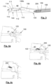
- Figs. 4a to 4c exhibit an exemplary placement sequence of an anchor 200 in a vertebra by means of the chisel 100 of the present invention, usually on the part of a surgeon during a prosthesis placement operation.
- an anchor 200 will have been placed in the chisel 100 in the conduit 106, preferably of circular cross section, secured by means of the screwing means 109 of the rod 107.
- the cutting mouth 103 of the chisel 100 will be placed against the vertebra onto which an anchor is to be screwed, as illustrated in Fig. 4a . After sufficiently carving the vertebra in the carving direction d1, as illustrated in Fig.
- the outlet direction d2 of the conduit 106 will advantageously enable the anchor 200 previously arranged in the conduit 106 and secured by means of the screwing means 109 of the rod 107 to be screwed in the outlet direction d2 as will be seen later in order to ensure the angle ⁇ with respect to the carving direction d1 in which the anchor 200 is fixed to a vertebra.
- this angle ⁇ will be an angle that is preferably acute in order to make it easier for the anchor to enter the vertebra, and more preferably less than 45 degrees in order to favour that the anchor is arranged essentially perpendicular to the spinal column. This angle will be predetermined during the manufacture of the chisel 100, conveniently sizing and positioning the parts thereof.
- the cutting mouth 103 comprises guiding means 112 of the carving direction d1, in this case a set of through holes aligned with respect to the carving direction d1 and which make it possible to track the carving of the chisel 100 by means of X-ray tracking or the like, such that the cutting mouth 103 being metal, the through holes are visible and the carving direction d1 can be tracked, enabling the surgeon to correct the carving direction d1.
- the cutting mouth 103 of the chisel 100 comprises a maximum carving mark 113, also by way of through hole, such that the surgeon can determine that the chisel 100 has already entered the vertebra sufficiently and that it is properly positioned to screw and place an anchor 200 previously placed in the conduit 106 in the vertebra.
- the surgeon when the chisel 100 is properly positioned, the surgeon must rotate the rotatable handle portion 104b, such that the screwing means 109 of the rod 107 advance rotating together with an anchor 200 placed in the screwing means 109 until exiting through the outlet 106b of the conduit 106, duly positioned and forming the predetermined angle ⁇ , such that, as the rotatable control portion 104b continues to rotate, the anchor 200 is screwed and inserted into the vertebra until it is sufficiently secured and placed in the vertebra, as illustrated in Fig. 4b , such that upon removal of the chisel 100, the anchor 200 is ready to subsequently receive a prosthesis, as shown in Fig. 4c .
- the cutting mouth 103 will have advantageously left a vertical straight cut in the vertebra suitable for subsequently housing an arm or appendix of the prosthesis.
- the latter must be positioned at a greater or lesser angle with respect to the carving direction d1 and must be inserted to a greater or lesser extent, also depending on the dimensions thereof, which may vary, for example, depending on whether they must withstand a greater or lesser force.
- the fixed handle portion 104a may be provided, for example, with a threaded shaft, and the rotatable handle portion may be provided with a thread complementary to the threaded shaft and adapted for joining and enabling the rotatable handle portion 104b to rotate with respect to the fixed handle portion.
- this threaded shaft and thread by means of sizing the passage of this threaded shaft and thread, it is possible to adjust the speed at which the rod 107 advances along the conduit. It is also intended to be able to size the threaded shaft and thread, as well as the handle 104, such that only a movement of the rod 107 equal to the length that it is desired for the anchor 200 to be inserted into the vertebra is enabled.
- the fixed handle portion 104a and the rotatable handle portion 104b can be sized to act as a stop when the rotatable handle portion 104b has been sufficiently rotated. It is also observed that the rod 107 will preferably be hollow and will be provided with perforations that enable the interior thereof to be cleaned and disinfected after use thereof.
- the handle 104 of the chisel 100 may also be provided with path limiting means of the rotation of the rotatable handle portion 104b with respect to the fixed handle portion 104a, for example, path limiting means of the rotation that not only enable the desired length for the anchor 200 to be inserted into the vertebra to be limited but also the final angular position thereof.
- path limiting means of the rotation can be, for example, a path end or stop formed in the complementary thread or the threaded shaft.
- the final angular position in which the anchor 200 will be arranged in the vertebra can be important if it has components on the surface thereof, for example, a lateral channel into which an appendix or arm of the prosthesis must be subsequently inserted, which must be properly positioned.
- Figure 5 exhibits a kit 1 for applying a prosthesis 400 in a vertebra by means of an anchor 200 and which comprises a chisel 100 adapted for placing an anchor 200 in a vertebra as previously described and applicator equipment 300 adapted for coupling a prosthesis 400 to an anchor 200 previously placed in the vertebra.
- the kit 1 may further comprise an anchor 200 adapted for being applied to a vertebra by means of the chisel 100 described above and a prosthesis 400 adapted for being coupled to the anchor 200 by the applicator equipment 300. It is intended that the chisel 100, the anchor 200, the applicator equipment 300 and the prosthesis 400 that are part of the kit 1 can further be manufactured, marketed or exhibited separately and independently.
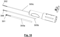
- Figure 6 exhibits the applicator equipment 300 of the kit 1.
- the applicator equipment 300 comprises at the end thereof securing means 301 of the prosthesis 400, which are adapted for securing the sleeve 401 of the prosthesis 400, as shown in Fig. 7 , and push means 302 of the prosthesis 400, adapted for pushing the prosthesis 400 out of the sleeve to couple it to the anchor 200.
- the applicator equipment 300 comprises a rotatable grip 303 connected to the push means 302 by means of a flexible screwdriver 305c, the grip 303 being adapted for carrying out a linear movement of the push means 302 when rotated and thus to progressively push the prosthesis 400 out of the sleeve to couple it to the anchor 200.
- the rotatable grip 303 of the applicator equipment 300 is connected with the securing means 301, with the push means 302 and with auxiliary push means 306, by means of respective concentric spindle nut assemblies 304a, 304b coupled to respective concentric tubes 305a, 305b removably coupled to the respective spindle 304a, 304b thereof, as can be seen in Fig. 8 , which illustrates a detailed cross section of the grip 303 of the applicator equipment 300.
- the applicator equipment 300 will enable a prosthesis 400 to be placed on an anchor 200 previously screwed into a vertebra, for example, in the manner previously described and illustrated in Fig. 4c .
- the prosthesis 400 will be moved closer to the anchor 200 as indicated in Fig. 9a , then turning the grip 303 of the applicator equipment 300 to carry out the linear movement of the push means 302 and progressively push the prosthesis 400, assisted by auxiliary push means 306, out of the sleeve 401, to couple it to the anchor 200.
- the anchor 200 is intended to be provided with a rear entry through which a projection of the prosthesis 400 can be inserted and locked, for example, by means of a leaf spring mechanism arranged on the projection of the prosthesis 400.
- the applicator equipment 300 can be removed, leaving the prosthesis 400 arranged and secured to the vertebra in operative position as illustrated in Fig. 9b .
- a specific type of prosthesis 400 is exhibited to illustrate the invention, other different types of prosthesis could alternatively be placed in the anchor 200 screwed to the vertebra, as appropriate.
- tubes 305a, 305b are intended to be removable from the respective spindle nut assemblies 304a, 304b thereof, as shown in Fig. 10 , thus enabling the applicator equipment 300 to be washed and disinfected after each use.
- the anchor 200 can be provided with a guide wire and the prosthesis 400 is provided with a through hole adapted for being traversed by this guide wire.
- the applicator equipment 300 could be provided with a passage adapted for receiving the end of the guide wire and thus easily guide the prosthesis 400 in the direction of the anchor 200.
- This guide wire can further be an electrical conductor, such that the applicator equipment 300 comprises an electrical warning circuit provided with two terminals adapted for generating a warning signal when the two terminals are electrically connected, one of the terminals being adapted for being connected to the guide wire and the other terminal being connected to the end of the push means 302.
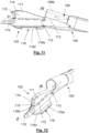
- Figs. 11 and 12 exhibit another embodiment of the cutting mouth 103 of a chisel 100 according to the invention, the remainder of the chisel 100 being as described above.
- the cutting mouth 103 comprises support means 116 to further facilitate the placing and carving of the chisel 100.
- These support means 116 which in the illustrated variant exhibit two fins 116a, 116b that extend in opposite directions in a direction perpendicular to the carving direction d1, determine a lower support surface 116c, such that the chisel 100 can be supported on a lower vertebra during the carving and screwing operation of the anchor as illustrated in Figs.
- the cutting edge 115 being inscribed in a plane perpendicular to the lower support surface 116c.
- the thickness of the support means 116 will be suitably sized such that it occupies the intervertebral space, such that as the lower support surface 116c rests on a lower vertebra, the cutting mouth 103 is correctly arranged on the vertebra immediately above.
Landscapes
- Health & Medical Sciences (AREA)
- Life Sciences & Earth Sciences (AREA)
- Orthopedic Medicine & Surgery (AREA)
- Surgery (AREA)
- Engineering & Computer Science (AREA)
- Biomedical Technology (AREA)
- Animal Behavior & Ethology (AREA)
- Heart & Thoracic Surgery (AREA)
- General Health & Medical Sciences (AREA)
- Public Health (AREA)
- Veterinary Medicine (AREA)
- Medical Informatics (AREA)
- Molecular Biology (AREA)
- Nuclear Medicine, Radiotherapy & Molecular Imaging (AREA)
- Oral & Maxillofacial Surgery (AREA)
- Neurology (AREA)
- Dentistry (AREA)
- Transplantation (AREA)
- Vascular Medicine (AREA)
- Cardiology (AREA)
- Physical Education & Sports Medicine (AREA)
- Surgical Instruments (AREA)
- Prostheses (AREA)
Description
- The chisel of the present invention is specially adapted for placing an anchor in a vertebra in order to subsequently be able to couple a prosthesis to the anchor, such that the prosthesis is properly positioned in the vertebra.
- During a surgical intervention to place a vertebral prosthesis, the positioning of the prosthesis to be placed in the vertebra must be carried out with precision, since an incorrect placement could prevent the correct functioning of the prosthesis, it even being necessary to intervene surgically again to reposition or remove the prosthesis.
- For the placement of prostheses in vertebrae, solutions are known based on first incorporating an anchor in a vertebra and subsequently coupling a prosthesis to said anchor, thus allowing, if the anchor is properly placed in the vertebra, the prosthesis to be properly placed when coupling the prosthesis to the anchor.
- This type of anchor can be placed by means of a chisel that enables the vertebra to be carved to expose the area in which the anchor will be fixed, to subsequently place the anchor in the exposed area carved by means of the chisel, for example, by screwing it with a screwdriver.
- However, as these types of anchors are very small, during the surgical intervention it is extremely difficult to be able to ensure that the anchor is properly placed in the vertebra, which can lead to unnecessary wear of the vertebra if several screwing attempts are carried out. Furthermore, it is also very difficult to insert the anchor sufficiently for it to be correctly secured to the vertebra without it being excessively inserted and not enabling the prosthesis to be correctly coupled.
- It is therefore an objective of the present invention to disclose a chisel that enables an anchor to be correctly placed in a vertebra so that a prosthesis subsequently coupled to the anchor is properly positioned.
- It is also another objective of the present invention to disclose a kit that enables a prosthesis to be placed in a vertebra using this chisel.
- Another objective is to disclose an alternative to known systems for placing vertebral prostheses.
- Document
US2017/007409 A1 discloses an exemplary chisel comprising a cutting mouth adapted for carving a vertebra with a hammer blow in a carving direction, and a handle provided with a fixed handle portion, the cutting mouth and the fixed handle portion being joined by an arm provided with a conduit with an outlet. - The chisel for placing an anchor in a vertebra of the present invention is one of those comprising a cutting mouth adapted for carving a vertebra with a hammer blow in a carving direction, and a handle, adapted for receiving the hammer blows and transmitting them to the cutting mouth. Essentially, the chisel is characterised in that the handle is provided with a fixed handle portion and a rotatable handle portion with respect to the cutting mouth, the cutting mouth and the fixed handle portion being joined by an arm provided with a conduit with an outlet that determines an outlet direction of the conduit, the rotatable handle portion being provided with a rod with a flexible portion and screwing means at the end thereof adapted for screwing an anchor, the rod being adapted for being inserted into the conduit and for advancing in the conduit by rotating the rotatable handle portion with respect to the cutting mouth to screw and place an anchor in a vertebra previously carved in the outlet direction of the conduit, such that the anchor is properly positioned in the vertebra for subsequently coupling a prosthesis.
- Preferably, the cutting mouth comprises a punch and a cutting fin, thus enabling the punch to mark and start perforating a point in the vertebra during the carving operation of a vertebra, from which the cutting fin will carve the vertebra, the vertebra portion cut by the fin further enabling the passage of a joining appendix of the prosthesis.
- In one embodiment, the cutting fin comprises a pointed projection that helps aid the initial positioning of the chisel against the vertebra, leaving the point slightly embedded in the vertebra, preventing the chisel from moving before carving.
- In an alternative embodiment, the cutting fin comprises a cutting edge between the punch and the pointed projection, enabling a cut to be made from the base of the vertebra to be carved, between the pointed projection and the punch. This cutting edge can have a general C-shape, thus enabling it to enter the vertebra progressively, facilitating the cutting thereof.
- In a variant of interest, the end of the punch is advanced in the carving direction with respect to the end of the pointed projection, such that when the chisel is applied against the vertebra, the end of the pointed projection is slightly embedded in the vertebra when the punch has already cut a portion of the base of the vertebra and has entered the intervertebral space by piercing the annulus fibrosus arranged between the vertebrae.
- In a variant embodiment, the cutting edge extends radially with respect to the carving direction, in order to thus enable a straight cut in the vertebra to be made that subsequently enables a portion of a prosthesis that is secured in the anchor to be housed. The cutting edge is intended to extend radially with respect to the carving direction in a vertical direction, to thus form a vertical straight cut in the vertebra.
- The cutting mouth of the chisel may be provided with guiding means of the carving direction, such that tracking is possible during the carving operation of the vertebra in order to verify that the vertebra is being carved in the correct direction. These guiding means of the carving direction can be a set of perforations aligned in the cutting mouth, such that if the cutting mouth is metal, it will be possible to track the carving direction for example by means of X-ray image. Naturally, the same effect will be achieved when the cutting mouth is radio-opaque to the rays from which the tracking image is generated.
- It is disclosed that the cutting mouth can also be provided with a maximum carving mark, which can also be a perforation in the cutting mouth, such that if the cutting mouth is metal, it will be possible to track the carving depth, for example, by means of X-ray image.
- In a variant embodiment, the fixed handle portion is provided with a threaded shaft, and the rotatable handle portion is provided with a thread complementary to the threaded shaft and adapted for enabling the rotatable handle portion to rotate with respect to the fixed handle portion, thus enabling the speed at which the rod advances along the conduit when rotating the rotatable handle portion to be adjusted, appropriately sizing the passage of this threaded shaft and thread. Naturally, it is intended that the thread passage of the handle is compatible with the thread passage of the anchor, such that the rotation and advancement of the rod can be correctly transmitted to the anchor during screwing of the anchor to the vertebra, for example, the thread passage of the anchor and that of the handle being equal. Alternatively, if the fixed handle portion is devoid of a threaded shaft, and the rotatable handle portion is devoid of a complementary thread, the advancement of the rod along the conduit will be conditioned by the thread passage of the anchor, when screwed to a vertebra.
- The handle will preferably be provided with path limiting means of the rotation of the rotatable handle portion with respect to the fixed handle portion, to thus limit the advancement of the rod through the conduit and limit the screwing depth of the anchor in the vertebra and furthermore, to be able to determine the final angular position of the screwing means and, consequently, of the anchor screwed to the vertebra. Being able to determine the final angular position of the anchor screwed into the vertebra is important in order to thus ensure that a prosthesis that is subsequently coupled to the anchor is properly positioned. Preferably, when the fixed handle portion is provided with a threaded shaft, and the rotatable handle portion is provided with a thread complementary to the threaded shaft and adapted for enabling the rotatable handle portion to rotate with respect to the fixed handle portion, the path limiting means can be a path end or a stop formed in the complementary thread or the threaded shaft, which will limit the rotation of the rotatable handle portion with respect to the fixed handle portion, said path limiting means being able to be incorporated during the manufacture of the threaded shaft or complementary thread.
- In one embodiment, the conduit comprises an angled section between the carving direction and the outlet direction, carrying out a smooth transition between the carving direction and the outlet direction of the conduit.
- In one embodiment, the cutting mouth comprises support means that enable the cutting mouth to be supported on a lower vertebra while the upper vertebra is being carved, thus enabling the stability of the chisel to be improved and making it easier to follow a correct carving direction, as well as enabling the operation of screwing and anchor placing to be carried out without the chisel moving.
- It is intended that these support means exhibit fins, such as two fins, which extend in opposite directions in a direction perpendicular to the carving direction, thus determining a suitable lower support surface for supporting the chisel on the vertebra immediately below during the carving operation.
- The present invention further discloses a kit for applying a prosthesis to a vertebra which comprises a chisel as described above adapted for placing an anchor in a vertebra and an applicator equipment adapted for coupling a prosthesis to the anchor previously placed in the vertebra by means of the chisel.
- The kit may further comprise an anchor adapted for being applied to a vertebra by means of the chisel and a prosthesis adapted for being coupled to the anchor by means of the applicator equipment.
- The prosthesis of the kit may be provided with a sleeve, the applicator equipment being provided with securing means of the prosthesis adapted for securing the sleeve of the prosthesis and push means of the prosthesis, adapted for pushing the prosthesis out of the sleeve to couple it to the anchor.
- In one embodiment, the applicator equipment of the kit comprises a rotatable grip connected to the push means, the grip being adapted for carrying out a linear movement of the push means when rotated.
- It is disclosed that the rotatable grip of the applicator equipment of the kit is also connected with the securing means, the grip being adapted for carrying out a linear movement in the opposite direction to the linear movement of the push means when rotated.
- It is also disclosed that the rotatable grip of the applicator equipment of the kit is connected to the securing means and the push means by means of respective concentric spindle nut assemblies coupled to concentric tubes.
- Preferably, the tubes of the applicator equipment of the kit are removably coupled to the spindle nut assemblies of the applicator equipment, such that they can be separated from the spindle nut assemblies to be disinfected after each use of the kit.
- As a complement to the present description, and for the purpose of helping to make the features of the invention more readily understandable, said description is accompanied by a set of drawings which, by way of illustration and not limitation, represent the following:
-
Figure 1 shows a chisel according to the present invention; -
Figure 2 shows the chisel ofFig. 1 disassembled; -
Figure 3 shows a detailed cross section of the cutting mouth of the chisel ofFig. 1 ; -
Figs. 4a to 4c show a screwing sequence of an anchor to a vertebra by means of the chisel ofFig. 1 ; -
Figure 5 shows a kit which comprises a chisel according to the present invention: -
Figure 6 shows an applicator device of the kit ofFig. 5 ; -
Figure 7 shows a detail of the end of the applicator device ofFig. 6 with a prosthesis included; -
Figure 8 shows a detailed view of the mechanism of the grip of the applicator device ofFig. 6 ; -
Figs. 9a and 9b show a placing sequence of a prosthesis by means of the applicator device ofFig. 6 in an anchor previously screwed to a vertebra; -
Figure 10 shows the applicator device ofFig. 6 disassembled; -
Figs. 11 and 12 show a detail of the cutting mouth of another chisel according to the present invention; - and
Figs. 13a to 13b show a screwing sequence of an anchor to a vertebra by means of the chisel provided with the cutting mouth ofFigs. 11 and 12 . - The
chisel 100 shown inFig. 1 is specially adapted for placing ananchor 200 in a vertebra. As can be seen, thechisel 100 comprises acutting mouth 103 adapted for carving a vertebra with a hammer blow in a carving direction d1, and ahandle 104, adapted for being struck by a hammer or the like, which is provided with afixed handle portion 104a and arotatable handle portion 104b with respect to thecutting mouth 103, thecutting mouth 103 andfixed handle portion 104a being joined by anarm 105. It should be noted that the carving direction d1 corresponds to the longitudinal direction of thechisel 100, such that the force exerted when striking thehandle 104 is transmitted through thearm 105 to thecutting mouth 103, which will carve or cut a vertebra in that direction. Thecutting mouth 103 is thus defined as the sharp part with which a chisel cuts, arranged at one end of the chisel. - As can also be seen in
Fig. 2 , thearm 105 that joins thecutting mouth 103 and thefixed handle portion 104a is advantageously provided with aconduit 106 with anoutlet 106b in thearm 105 which determines an outlet direction d2 of theconduit 106 and aninlet 106a in thefixed handle portion 104a, therotatable handle portion 104b being provided with arod 107 with aflexible portion 108 and screwing means 109 at the end thereof, such as a screwdriver bit, adapted for securing and screwing ananchor 200, therod 107 being adapted for being inserted into theconduit 106 and for advancing in theconduit 106 by rotating therotatable handle portion 104b with respect to thecutting mouth 103 to screw and place ananchor 200 in the vertebra previously inserted in theconduit 106, by way of screwdriver. It is intended that theconduit 106 exhibits an angled section between the carving direction d1 and the outlet direction d2. - As can be seen in the detail of the end of the
chisel 100 exhibited inFig. 3 , the cuttingmouth 103 comprises apunch 110 and a cuttingfin 111 arranged on the punch, such that thepunch 110 enables the carving of the vertebra to start and thus being able to correctly direct thechisel 100 before the cuttingfin 111 carves the vertebra to a greater extent, for example by opening a passageway to subsequently house a prosthesis appendage or arm in theanchor 200. It is further observed that the cuttingfin 111 of thechisel 100 comprises apointed projection 114 to favour the securing of the cuttingfin 111 during the carving operation. For this securing to be achieved, the end of thepunch 110 is advanced in the carving direction d1 with respect to the end of the pointedprojection 114, such that when the pointedprojection 114 is applied against the vertebra, thepunch 110 has already entered the intervertebral space and carved the base of the vertebra. To carry out the carving operation, it is observed that the cuttingfin 111 comprises acutting edge 115 in a general C-shape that extends radially with respect to the carving direction d1, in order to thus enable a vertical straight cut to be formed in the vertebra between thepunch 110 and thepointed projection 114. -
Figs. 4a to 4c exhibit an exemplary placement sequence of ananchor 200 in a vertebra by means of thechisel 100 of the present invention, usually on the part of a surgeon during a prosthesis placement operation. Previously, ananchor 200 will have been placed in thechisel 100 in theconduit 106, preferably of circular cross section, secured by means of the screwing means 109 of therod 107. First, the cuttingmouth 103 of thechisel 100 will be placed against the vertebra onto which an anchor is to be screwed, as illustrated inFig. 4a . After sufficiently carving the vertebra in the carving direction d1, as illustrated inFig. 4a , the outlet direction d2 of theconduit 106 will advantageously enable theanchor 200 previously arranged in theconduit 106 and secured by means of the screwing means 109 of therod 107 to be screwed in the outlet direction d2 as will be seen later in order to ensure the angle α with respect to the carving direction d1 in which theanchor 200 is fixed to a vertebra. Naturally, this angle α will be an angle that is preferably acute in order to make it easier for the anchor to enter the vertebra, and more preferably less than 45 degrees in order to favour that the anchor is arranged essentially perpendicular to the spinal column. This angle will be predetermined during the manufacture of thechisel 100, conveniently sizing and positioning the parts thereof. - In order to maintain the carving direction d1 and ensure that the
chisel 100 is correctly inserted into the vertebra, the cuttingmouth 103 comprises guiding means 112 of the carving direction d1, in this case a set of through holes aligned with respect to the carving direction d1 and which make it possible to track the carving of thechisel 100 by means of X-ray tracking or the like, such that the cuttingmouth 103 being metal, the through holes are visible and the carving direction d1 can be tracked, enabling the surgeon to correct the carving direction d1. - Furthermore, it is intended that the cutting
mouth 103 of thechisel 100 comprises amaximum carving mark 113, also by way of through hole, such that the surgeon can determine that thechisel 100 has already entered the vertebra sufficiently and that it is properly positioned to screw and place ananchor 200 previously placed in theconduit 106 in the vertebra. - At this time, when the
chisel 100 is properly positioned, the surgeon must rotate therotatable handle portion 104b, such that the screwing means 109 of therod 107 advance rotating together with ananchor 200 placed in the screwing means 109 until exiting through theoutlet 106b of theconduit 106, duly positioned and forming the predetermined angle α, such that, as therotatable control portion 104b continues to rotate, theanchor 200 is screwed and inserted into the vertebra until it is sufficiently secured and placed in the vertebra, as illustrated inFig. 4b , such that upon removal of thechisel 100, theanchor 200 is ready to subsequently receive a prosthesis, as shown inFig. 4c . Furthermore, it should be noted that the cuttingmouth 103 will have advantageously left a vertical straight cut in the vertebra suitable for subsequently housing an arm or appendix of the prosthesis. Naturally, depending on the type of prosthesis to be included in theanchor 200, the latter must be positioned at a greater or lesser angle with respect to the carving direction d1 and must be inserted to a greater or lesser extent, also depending on the dimensions thereof, which may vary, for example, depending on whether they must withstand a greater or lesser force. - Naturally, the fixed
handle portion 104a may be provided, for example, with a threaded shaft, and the rotatable handle portion may be provided with a thread complementary to the threaded shaft and adapted for joining and enabling therotatable handle portion 104b to rotate with respect to the fixed handle portion. In this case, by means of sizing the passage of this threaded shaft and thread, it is possible to adjust the speed at which therod 107 advances along the conduit. It is also intended to be able to size the threaded shaft and thread, as well as thehandle 104, such that only a movement of therod 107 equal to the length that it is desired for theanchor 200 to be inserted into the vertebra is enabled. In this way, the fixedhandle portion 104a and therotatable handle portion 104b can be sized to act as a stop when therotatable handle portion 104b has been sufficiently rotated. It is also observed that therod 107 will preferably be hollow and will be provided with perforations that enable the interior thereof to be cleaned and disinfected after use thereof. - The
handle 104 of thechisel 100 may also be provided with path limiting means of the rotation of therotatable handle portion 104b with respect to the fixedhandle portion 104a, for example, path limiting means of the rotation that not only enable the desired length for theanchor 200 to be inserted into the vertebra to be limited but also the final angular position thereof. These path limiting means of the rotation can be, for example, a path end or stop formed in the complementary thread or the threaded shaft. The final angular position in which theanchor 200 will be arranged in the vertebra can be important if it has components on the surface thereof, for example, a lateral channel into which an appendix or arm of the prosthesis must be subsequently inserted, which must be properly positioned. -
Figure 5 exhibits a kit 1 for applying aprosthesis 400 in a vertebra by means of ananchor 200 and which comprises achisel 100 adapted for placing ananchor 200 in a vertebra as previously described andapplicator equipment 300 adapted for coupling aprosthesis 400 to ananchor 200 previously placed in the vertebra. Naturally the kit 1 may further comprise ananchor 200 adapted for being applied to a vertebra by means of thechisel 100 described above and aprosthesis 400 adapted for being coupled to theanchor 200 by theapplicator equipment 300. It is intended that thechisel 100, theanchor 200, theapplicator equipment 300 and theprosthesis 400 that are part of the kit 1 can further be manufactured, marketed or exhibited separately and independently. -
Figure 6 exhibits theapplicator equipment 300 of the kit 1. As can be observed, theapplicator equipment 300 comprises at the end thereof securing means 301 of theprosthesis 400, which are adapted for securing thesleeve 401 of theprosthesis 400, as shown inFig. 7 , and push means 302 of theprosthesis 400, adapted for pushing theprosthesis 400 out of the sleeve to couple it to theanchor 200. - In order to carry out the pushing action of the
prosthesis 400, theapplicator equipment 300 comprises arotatable grip 303 connected to the push means 302 by means of aflexible screwdriver 305c, thegrip 303 being adapted for carrying out a linear movement of the push means 302 when rotated and thus to progressively push theprosthesis 400 out of the sleeve to couple it to theanchor 200. - Furthermore, the
rotatable grip 303 of theapplicator equipment 300 is connected with the securing means 301, with the push means 302 and with auxiliary push means 306, by means of respective concentricspindle nut assemblies concentric tubes respective spindle Fig. 8 , which illustrates a detailed cross section of thegrip 303 of theapplicator equipment 300. - The
applicator equipment 300 will enable aprosthesis 400 to be placed on ananchor 200 previously screwed into a vertebra, for example, in the manner previously described and illustrated inFig. 4c . Thus, by means of theapplicator equipment 300, theprosthesis 400 will be moved closer to theanchor 200 as indicated inFig. 9a , then turning thegrip 303 of theapplicator equipment 300 to carry out the linear movement of the push means 302 and progressively push theprosthesis 400, assisted by auxiliary push means 306, out of thesleeve 401, to couple it to theanchor 200. Theanchor 200 is intended to be provided with a rear entry through which a projection of theprosthesis 400 can be inserted and locked, for example, by means of a leaf spring mechanism arranged on the projection of theprosthesis 400. After theprosthesis 400 is correctly locked in theanchor 200, theapplicator equipment 300 can be removed, leaving theprosthesis 400 arranged and secured to the vertebra in operative position as illustrated inFig. 9b . Naturally, although a specific type ofprosthesis 400 is exhibited to illustrate the invention, other different types of prosthesis could alternatively be placed in theanchor 200 screwed to the vertebra, as appropriate. - Advantageously,
tubes spindle nut assemblies Fig. 10 , thus enabling theapplicator equipment 300 to be washed and disinfected after each use. - It is also intended that the
anchor 200 can be provided with a guide wire and theprosthesis 400 is provided with a through hole adapted for being traversed by this guide wire. In this case, theapplicator equipment 300 could be provided with a passage adapted for receiving the end of the guide wire and thus easily guide theprosthesis 400 in the direction of theanchor 200. This guide wire can further be an electrical conductor, such that theapplicator equipment 300 comprises an electrical warning circuit provided with two terminals adapted for generating a warning signal when the two terminals are electrically connected, one of the terminals being adapted for being connected to the guide wire and the other terminal being connected to the end of the push means 302. -
Figs. 11 and 12 exhibit another embodiment of the cuttingmouth 103 of achisel 100 according to the invention, the remainder of thechisel 100 being as described above. In this embodiment, the cuttingmouth 103 comprises support means 116 to further facilitate the placing and carving of thechisel 100. These support means 116, which in the illustrated variant exhibit twofins lower support surface 116c, such that thechisel 100 can be supported on a lower vertebra during the carving and screwing operation of the anchor as illustrated inFigs. 13a and 13b , thecutting edge 115 being inscribed in a plane perpendicular to thelower support surface 116c. Naturally, the thickness of the support means 116 will be suitably sized such that it occupies the intervertebral space, such that as thelower support surface 116c rests on a lower vertebra, the cuttingmouth 103 is correctly arranged on the vertebra immediately above.
Claims (15)
- A chisel (100) for placing an anchor (200) in a vertebra, which comprises a cutting mouth (103) adapted for carving a vertebra with a hammer blow in a carving direction (d1), and a handle (104) provided with a fixed handle portion (104a) and a rotatable handle portion (104b) with respect to the cutting mouth, the cutting mouth and the fixed handle portion being joined by an arm (105) provided with a conduit (106) with an outlet (106b) that determines an outlet direction of the conduit (d2), the rotatable handle portion being provided with a rod (107) with a flexible portion (108) and screwing means (109) at the end thereof adapted for screwing an anchor, the rod being adapted for being inserted into the conduit and for advancing in the conduit by rotating the rotatable handle portion with respect to the cutting mouth to screw and place an anchor in the vertebra previously carved in the outlet direction of the conduit.
- The chisel (100) according to the preceding claim, characterised in that the cutting mouth (103) comprises a punch (110) and a cutting fin (111).
- The chisel (100) according to the preceding claim, characterised in that the cutting fin (111) comprises a pointed projection (114).
- The chisel (100) according to the preceding claim, characterised in that the cutting fin (111) comprises a cutting edge (115) between the punch (110) and the pointed projection (114).
- The chisel (100) according to the preceding claim, characterised in that the cutting edge (115) extends radially with respect to the carving direction (d1).
- The chisel (100) according to any one of claims 3 to 5, characterised in that the end of the punch (110) is advanced with respect to the end of the pointed projection (114) in the carving direction (d1).
- The chisel (100) according to any one of the preceding claims, characterised in that the cutting mouth (103) comprises guiding means (112) of the carving direction (d1).
- The chisel (100) according to any one of the preceding claims, characterised in that the cutting mouth (103) comprises a maximum carving mark (113).
- The chisel (100) according to any one of the preceding claims, characterised in that the conduit (106) comprises an angled section.
- The chisel (100) according to any one of the preceding claims, characterised in that the fixed handle portion (104a) is provided with a threaded shaft, and the rotatable handle portion (104b) is provided with a thread complementary to the threaded shaft and adapted for enabling the rotatable handle portion to rotate with respect to the fixed handle portion.
- The chisel (100) according to any one of the preceding claims, characterised in that the handle (104) is provided with path limiting means of the rotation of the rotatable handle portion (104b) with respect to the fixed handle portion (104a).
- The chisel (100) according to the preceding claim, characterised in that the fixed handle portion (104a) being provided with a threaded shaft, and the rotatable handle portion (104b) being provided with a thread complementary to the threaded shaft adapted for enabling the rotatable handle portion to rotate with respect to the fixed handle portion, the path limiting means are a path end or a stop formed in the complementary thread or the threaded shaft.
- The chisel (100) according to any one of the preceding claims, characterised in that the cutting mouth (103) comprises support means (116).
- The chisel (100) according to the preceding claim, characterised in that the support means (116) exhibit fins (116a, 116b) that extend in opposite directions in a direction perpendicular to the carving direction (d1), determining a lower support surface (116c).
- A kit (1) for applying a prosthesis to a vertebra which comprises:a. A chisel (100) according to any one of claims 1 to 14 adapted for placing an anchor (200) in a vertebra; andb. An applicator equipment (300) adapted for coupling a prosthesis (400) in an anchor previously placed in the vertebra.
Applications Claiming Priority (2)
| Application Number | Priority Date | Filing Date | Title |
|---|---|---|---|
| ES201931564U ES1238209Y (en) | 2019-09-27 | 2019-09-27 | Chisel to place an anchor on a vertebra |
| PCT/ES2020/070574 WO2021058848A1 (en) | 2019-09-27 | 2020-09-25 | Chisel for placing an anchor in a vertebra |
Publications (3)
| Publication Number | Publication Date |
|---|---|
| EP4035612A1 EP4035612A1 (en) | 2022-08-03 |
| EP4035612C0 EP4035612C0 (en) | 2023-11-01 |
| EP4035612B1 true EP4035612B1 (en) | 2023-11-01 |
Family
ID=68653653
Family Applications (1)
| Application Number | Title | Priority Date | Filing Date |
|---|---|---|---|
| EP20803625.1A Active EP4035612B1 (en) | 2019-09-27 | 2020-09-25 | Chisel for placing an anchor in a vertebra |
Country Status (7)
| Country | Link |
|---|---|
| US (1) | US12011180B2 (en) |
| EP (1) | EP4035612B1 (en) |
| CN (1) | CN114466623B (en) |
| BR (1) | BR212022004707U2 (en) |
| ES (2) | ES1238209Y (en) |
| PL (1) | PL4035612T3 (en) |
| WO (1) | WO2021058848A1 (en) |
Families Citing this family (7)
| Publication number | Priority date | Publication date | Assignee | Title |
|---|---|---|---|---|
| US10390877B2 (en) | 2011-12-30 | 2019-08-27 | Relievant Medsystems, Inc. | Systems and methods for treating back pain |
| AU2013337680B2 (en) | 2012-11-05 | 2019-04-18 | Relievant Medsystems, Inc. | Systems and methods for creating curved paths through bone and modulating nerves within the bone |
| WO2021050767A1 (en) | 2019-09-12 | 2021-03-18 | Relievant Medsystems, Inc. | Systems and methods for tissue modulation |
| AU2021306313A1 (en) | 2020-07-10 | 2023-03-02 | Relievant Medsystems, Inc. | Vertebral denervation in conjunction with vertebral fusion |
| US12082876B1 (en) | 2020-09-28 | 2024-09-10 | Relievant Medsystems, Inc. | Introducer drill |
| EP4268150A4 (en) | 2020-12-22 | 2024-12-18 | Relievant Medsystems, Inc. | PREDICTION OF CANDIDATES FOR SPINAL NEUROMODULATION |
| US12433668B1 (en) | 2021-11-08 | 2025-10-07 | Relievant Medsystems, Inc. | Impedance stoppage mitigation during radiofrequency tissue ablation procedures |
Family Cites Families (12)
| Publication number | Priority date | Publication date | Assignee | Title |
|---|---|---|---|---|
| US6436101B1 (en) * | 1999-10-13 | 2002-08-20 | James S. Hamada | Rasp for use in spine surgery |
| US8025684B2 (en) * | 2001-11-09 | 2011-09-27 | Zimmer Spine, Inc. | Instruments and methods for inserting a spinal implant |
| US7988693B2 (en) * | 2002-07-19 | 2011-08-02 | Warsaw Orthopedic, Inc. | Chisels and procedure for insertion of spinal implant in a spinal disc space |
| US20050090829A1 (en) * | 2003-10-23 | 2005-04-28 | Osteotech, Inc. | Spinal bone chisels |
| US7527638B2 (en) * | 2003-12-16 | 2009-05-05 | Depuy Spine, Inc. | Methods and devices for minimally invasive spinal fixation element placement |
| WO2009094493A2 (en) * | 2006-11-03 | 2009-07-30 | Innovative Spine | Spinal access systems and methods |
| EP2813190B1 (en) * | 2007-02-22 | 2017-04-26 | Spinal Elements, Inc. | Vertebral facet joint drill |
| US20120323242A1 (en) * | 2011-06-16 | 2012-12-20 | Industrial Technology Research Institute | Surgical awl and method of using the same |
| US10363140B2 (en) * | 2012-03-09 | 2019-07-30 | Si-Bone Inc. | Systems, device, and methods for joint fusion |
| WO2014089535A1 (en) * | 2012-12-07 | 2014-06-12 | Providence Medical Technology, Inc. | Apparatus and method for bone screw deployment |
| CN104688296B (en) * | 2015-03-18 | 2018-02-02 | 马克 | The snakelike puncture bone cone of one kind orientation |
| RU179538U1 (en) * | 2017-06-20 | 2018-05-17 | федеральное государственное бюджетное учреждение "Российский научный центр "Восстановительная травматология и ортопедия" имени академика Г.А. Илизарова" Министерства здравоохранения Российской Федерации (ФГБУ "РНЦ "ВТО" им. акад. Г.А. Илизарова" Минздрава России | S-SHAPED CHANNEL BIT FOR BONE PROCESSING |
-
2019
- 2019-09-27 ES ES201931564U patent/ES1238209Y/en active Active
-
2020
- 2020-09-25 ES ES20803625T patent/ES2968607T3/en active Active
- 2020-09-25 WO PCT/ES2020/070574 patent/WO2021058848A1/en not_active Ceased
- 2020-09-25 EP EP20803625.1A patent/EP4035612B1/en active Active
- 2020-09-25 CN CN202080067676.6A patent/CN114466623B/en active Active
- 2020-09-25 BR BR212022004707U patent/BR212022004707U2/en not_active Application Discontinuation
- 2020-09-25 PL PL20803625.1T patent/PL4035612T3/en unknown
-
2021
- 2021-04-01 US US17/220,106 patent/US12011180B2/en active Active
Also Published As
| Publication number | Publication date |
|---|---|
| WO2021058848A1 (en) | 2021-04-01 |
| CN114466623B (en) | 2024-10-18 |
| US20210290254A1 (en) | 2021-09-23 |
| EP4035612C0 (en) | 2023-11-01 |
| PL4035612T3 (en) | 2024-03-11 |
| BR212022004707U2 (en) | 2022-07-12 |
| ES1238209U (en) | 2019-11-29 |
| ES1238209Y (en) | 2020-02-20 |
| EP4035612A1 (en) | 2022-08-03 |
| ES2968607T3 (en) | 2024-05-13 |
| US12011180B2 (en) | 2024-06-18 |
| CN114466623A (en) | 2022-05-10 |
Similar Documents
| Publication | Publication Date | Title |
|---|---|---|
| EP4035612A1 (en) | Chisel for placing an anchor in a vertebra | |
| US7763024B2 (en) | Adjustable cutting of cutout in vertebral bone | |
| US4399813A (en) | Apparatus and method for removing a prosthesis embedded in skeletal bone | |
| US10182831B2 (en) | Instruments and method for preparing an intervertebral space for receiving an artificial disc implant | |
| DE69826037T2 (en) | DRIVING DEVICE FOR SURGICAL NAILS | |
| US7135026B2 (en) | Laparoscopic spinal stabilization surgical method | |
| US7255702B2 (en) | Bone milling instrument | |
| JP2983485B2 (en) | Patella cutting instrument | |
| EP0506213A1 (en) | Drill pin guide and method for orthopedic surgery | |
| US20170100260A1 (en) | Insertion tool for implant and methods of use | |
| KR19990083369A (en) | Device removal kit and method therefor | |
| US7575579B2 (en) | Drill guide tissue protector | |
| SE517237C2 (en) | Directional instrument for performing cutting of a femoral neck | |
| CN105050507A (en) | Soft tissue displacer tool and with inclined groove and methods | |
| US20240032968A1 (en) | Minimally invasive surgery guide wire capturing instrumentation | |
| US10631880B1 (en) | Cannulated modular magnetic glenoid reamer | |
| JP4728964B2 (en) | Tool set for inserting intervertebral joint prostheses | |
| US11123086B1 (en) | Cannulated modular magnetic glenoid reamer | |
| CN109259846B (en) | Humerus head resetting holding forceps | |
| CN113271869B (en) | Punch machine integrated suture anchor device | |
| WO2013179002A1 (en) | A trial instrument for use in orthopaedic surgery |
Legal Events
| Date | Code | Title | Description |
|---|---|---|---|
| STAA | Information on the status of an ep patent application or granted ep patent |
Free format text: STATUS: UNKNOWN |
|
| STAA | Information on the status of an ep patent application or granted ep patent |
Free format text: STATUS: THE INTERNATIONAL PUBLICATION HAS BEEN MADE |
|
| PUAI | Public reference made under article 153(3) epc to a published international application that has entered the european phase |
Free format text: ORIGINAL CODE: 0009012 |
|
| STAA | Information on the status of an ep patent application or granted ep patent |
Free format text: STATUS: REQUEST FOR EXAMINATION WAS MADE |
|
| 17P | Request for examination filed |
Effective date: 20220329 |
|
| AK | Designated contracting states |
Kind code of ref document: A1 Designated state(s): AL AT BE BG CH CY CZ DE DK EE ES FI FR GB GR HR HU IE IS IT LI LT LU LV MC MK MT NL NO PL PT RO RS SE SI SK SM TR |
|
| DAV | Request for validation of the european patent (deleted) | ||
| DAX | Request for extension of the european patent (deleted) | ||
| GRAP | Despatch of communication of intention to grant a patent |
Free format text: ORIGINAL CODE: EPIDOSNIGR1 |
|
| STAA | Information on the status of an ep patent application or granted ep patent |
Free format text: STATUS: GRANT OF PATENT IS INTENDED |
|
| INTG | Intention to grant announced |
Effective date: 20230503 |
|
| GRAS | Grant fee paid |
Free format text: ORIGINAL CODE: EPIDOSNIGR3 |
|
| GRAA | (expected) grant |
Free format text: ORIGINAL CODE: 0009210 |
|
| STAA | Information on the status of an ep patent application or granted ep patent |
Free format text: STATUS: THE PATENT HAS BEEN GRANTED |
|
| AK | Designated contracting states |
Kind code of ref document: B1 Designated state(s): AL AT BE BG CH CY CZ DE DK EE ES FI FR GB GR HR HU IE IS IT LI LT LU LV MC MK MT NL NO PL PT RO RS SE SI SK SM TR |
|
| REG | Reference to a national code |
Ref country code: GB Ref legal event code: FG4D |
|
| REG | Reference to a national code |
Ref country code: CH Ref legal event code: EP |
|
| REG | Reference to a national code |
Ref country code: DE Ref legal event code: R096 Ref document number: 602020020409 Country of ref document: DE |
|
| REG | Reference to a national code |
Ref country code: IE Ref legal event code: FG4D |
|
| U01 | Request for unitary effect filed |
Effective date: 20231128 |
|
| U07 | Unitary effect registered |
Designated state(s): AT BE BG DE DK EE FI FR IT LT LU LV MT NL PT SE SI Effective date: 20231207 |
|
| PG25 | Lapsed in a contracting state [announced via postgrant information from national office to epo] |
Ref country code: GR Free format text: LAPSE BECAUSE OF FAILURE TO SUBMIT A TRANSLATION OF THE DESCRIPTION OR TO PAY THE FEE WITHIN THE PRESCRIBED TIME-LIMIT Effective date: 20240202 |
|
| PG25 | Lapsed in a contracting state [announced via postgrant information from national office to epo] |
Ref country code: IS Free format text: LAPSE BECAUSE OF FAILURE TO SUBMIT A TRANSLATION OF THE DESCRIPTION OR TO PAY THE FEE WITHIN THE PRESCRIBED TIME-LIMIT Effective date: 20240301 |
|
| PG25 | Lapsed in a contracting state [announced via postgrant information from national office to epo] |
Ref country code: IS Free format text: LAPSE BECAUSE OF FAILURE TO SUBMIT A TRANSLATION OF THE DESCRIPTION OR TO PAY THE FEE WITHIN THE PRESCRIBED TIME-LIMIT Effective date: 20240301 Ref country code: GR Free format text: LAPSE BECAUSE OF FAILURE TO SUBMIT A TRANSLATION OF THE DESCRIPTION OR TO PAY THE FEE WITHIN THE PRESCRIBED TIME-LIMIT Effective date: 20240202 |
|
| REG | Reference to a national code |
Ref country code: ES Ref legal event code: FG2A Ref document number: 2968607 Country of ref document: ES Kind code of ref document: T3 Effective date: 20240513 |
|
| PG25 | Lapsed in a contracting state [announced via postgrant information from national office to epo] |
Ref country code: RS Free format text: LAPSE BECAUSE OF FAILURE TO SUBMIT A TRANSLATION OF THE DESCRIPTION OR TO PAY THE FEE WITHIN THE PRESCRIBED TIME-LIMIT Effective date: 20231101 Ref country code: NO Free format text: LAPSE BECAUSE OF FAILURE TO SUBMIT A TRANSLATION OF THE DESCRIPTION OR TO PAY THE FEE WITHIN THE PRESCRIBED TIME-LIMIT Effective date: 20240201 Ref country code: HR Free format text: LAPSE BECAUSE OF FAILURE TO SUBMIT A TRANSLATION OF THE DESCRIPTION OR TO PAY THE FEE WITHIN THE PRESCRIBED TIME-LIMIT Effective date: 20231101 |
|
| PG25 | Lapsed in a contracting state [announced via postgrant information from national office to epo] |
Ref country code: CZ Free format text: LAPSE BECAUSE OF FAILURE TO SUBMIT A TRANSLATION OF THE DESCRIPTION OR TO PAY THE FEE WITHIN THE PRESCRIBED TIME-LIMIT Effective date: 20231101 |
|
| PG25 | Lapsed in a contracting state [announced via postgrant information from national office to epo] |
Ref country code: SK Free format text: LAPSE BECAUSE OF FAILURE TO SUBMIT A TRANSLATION OF THE DESCRIPTION OR TO PAY THE FEE WITHIN THE PRESCRIBED TIME-LIMIT Effective date: 20231101 |
|
| PG25 | Lapsed in a contracting state [announced via postgrant information from national office to epo] |
Ref country code: SM Free format text: LAPSE BECAUSE OF FAILURE TO SUBMIT A TRANSLATION OF THE DESCRIPTION OR TO PAY THE FEE WITHIN THE PRESCRIBED TIME-LIMIT Effective date: 20231101 Ref country code: SK Free format text: LAPSE BECAUSE OF FAILURE TO SUBMIT A TRANSLATION OF THE DESCRIPTION OR TO PAY THE FEE WITHIN THE PRESCRIBED TIME-LIMIT Effective date: 20231101 Ref country code: CZ Free format text: LAPSE BECAUSE OF FAILURE TO SUBMIT A TRANSLATION OF THE DESCRIPTION OR TO PAY THE FEE WITHIN THE PRESCRIBED TIME-LIMIT Effective date: 20231101 |
|
| REG | Reference to a national code |
Ref country code: DE Ref legal event code: R097 Ref document number: 602020020409 Country of ref document: DE |
|
| PLBE | No opposition filed within time limit |
Free format text: ORIGINAL CODE: 0009261 |
|
| STAA | Information on the status of an ep patent application or granted ep patent |
Free format text: STATUS: NO OPPOSITION FILED WITHIN TIME LIMIT |
|
| U20 | Renewal fee for the european patent with unitary effect paid |
Year of fee payment: 5 Effective date: 20240826 |
|
| 26N | No opposition filed |
Effective date: 20240802 |
|
| PG25 | Lapsed in a contracting state [announced via postgrant information from national office to epo] |
Ref country code: MC Free format text: LAPSE BECAUSE OF FAILURE TO SUBMIT A TRANSLATION OF THE DESCRIPTION OR TO PAY THE FEE WITHIN THE PRESCRIBED TIME-LIMIT Effective date: 20231101 |
|
| PG25 | Lapsed in a contracting state [announced via postgrant information from national office to epo] |
Ref country code: IE Free format text: LAPSE BECAUSE OF NON-PAYMENT OF DUE FEES Effective date: 20240925 |
|
| PG25 | Lapsed in a contracting state [announced via postgrant information from national office to epo] |
Ref country code: RO Free format text: LAPSE BECAUSE OF FAILURE TO SUBMIT A TRANSLATION OF THE DESCRIPTION OR TO PAY THE FEE WITHIN THE PRESCRIBED TIME-LIMIT Effective date: 20231101 |
|
| PG25 | Lapsed in a contracting state [announced via postgrant information from national office to epo] |
Ref country code: CY Free format text: LAPSE BECAUSE OF FAILURE TO SUBMIT A TRANSLATION OF THE DESCRIPTION OR TO PAY THE FEE WITHIN THE PRESCRIBED TIME-LIMIT; INVALID AB INITIO Effective date: 20200925 |
|
| REG | Reference to a national code |
Ref country code: CH Ref legal event code: U11 Free format text: ST27 STATUS EVENT CODE: U-0-0-U10-U11 (AS PROVIDED BY THE NATIONAL OFFICE) Effective date: 20260204 |
|
| PG25 | Lapsed in a contracting state [announced via postgrant information from national office to epo] |
Ref country code: HU Free format text: LAPSE BECAUSE OF FAILURE TO SUBMIT A TRANSLATION OF THE DESCRIPTION OR TO PAY THE FEE WITHIN THE PRESCRIBED TIME-LIMIT; INVALID AB INITIO Effective date: 20200925 |
|
| U21 | Renewal fee for the european patent with unitary effect paid with additional fee |
Year of fee payment: 6 Effective date: 20260213 |
|
| PGFP | Annual fee paid to national office [announced via postgrant information from national office to epo] |
Ref country code: GB Payment date: 20260213 Year of fee payment: 6 |
|
| PGFP | Annual fee paid to national office [announced via postgrant information from national office to epo] |
Ref country code: ES Payment date: 20260211 Year of fee payment: 6 |
|
| PGFP | Annual fee paid to national office [announced via postgrant information from national office to epo] |
Ref country code: TR Payment date: 20260217 Year of fee payment: 6 |
|
| PGFP | Annual fee paid to national office [announced via postgrant information from national office to epo] |
Ref country code: CH Payment date: 20260204 Year of fee payment: 6 |
|
| PGFP | Annual fee paid to national office [announced via postgrant information from national office to epo] |
Ref country code: PL Payment date: 20260204 Year of fee payment: 6 |