EP4035514A1 - System and method for controlling the operation of an agricultural implement based on compaction layer position - Google Patents
System and method for controlling the operation of an agricultural implement based on compaction layer position Download PDFInfo
- Publication number
- EP4035514A1 EP4035514A1 EP22154085.9A EP22154085A EP4035514A1 EP 4035514 A1 EP4035514 A1 EP 4035514A1 EP 22154085 A EP22154085 A EP 22154085A EP 4035514 A1 EP4035514 A1 EP 4035514A1
- Authority
- EP
- European Patent Office
- Prior art keywords
- compaction layer
- ground
- computing system
- field
- penetrating tool
- Prior art date
- Legal status (The legal status is an assumption and is not a legal conclusion. Google has not performed a legal analysis and makes no representation as to the accuracy of the status listed.)
- Pending
Links
Images


Classifications
-
- A—HUMAN NECESSITIES
- A01—AGRICULTURE; FORESTRY; ANIMAL HUSBANDRY; HUNTING; TRAPPING; FISHING
- A01B—SOIL WORKING IN AGRICULTURE OR FORESTRY; PARTS, DETAILS, OR ACCESSORIES OF AGRICULTURAL MACHINES OR IMPLEMENTS, IN GENERAL
- A01B63/00—Lifting or adjusting devices or arrangements for agricultural machines or implements
- A01B63/02—Lifting or adjusting devices or arrangements for agricultural machines or implements for implements mounted on tractors
- A01B63/10—Lifting or adjusting devices or arrangements for agricultural machines or implements for implements mounted on tractors operated by hydraulic or pneumatic means
- A01B63/111—Lifting or adjusting devices or arrangements for agricultural machines or implements for implements mounted on tractors operated by hydraulic or pneumatic means regulating working depth of implements
- A01B63/1112—Lifting or adjusting devices or arrangements for agricultural machines or implements for implements mounted on tractors operated by hydraulic or pneumatic means regulating working depth of implements using a non-tactile ground distance measurement, e.g. using reflection of waves
-
- A—HUMAN NECESSITIES
- A01—AGRICULTURE; FORESTRY; ANIMAL HUSBANDRY; HUNTING; TRAPPING; FISHING
- A01B—SOIL WORKING IN AGRICULTURE OR FORESTRY; PARTS, DETAILS, OR ACCESSORIES OF AGRICULTURAL MACHINES OR IMPLEMENTS, IN GENERAL
- A01B63/00—Lifting or adjusting devices or arrangements for agricultural machines or implements
- A01B63/14—Lifting or adjusting devices or arrangements for agricultural machines or implements for implements drawn by animals or tractors
- A01B63/24—Tools or tool-holders adjustable relatively to the frame
-
- A—HUMAN NECESSITIES
- A01—AGRICULTURE; FORESTRY; ANIMAL HUSBANDRY; HUNTING; TRAPPING; FISHING
- A01B—SOIL WORKING IN AGRICULTURE OR FORESTRY; PARTS, DETAILS, OR ACCESSORIES OF AGRICULTURAL MACHINES OR IMPLEMENTS, IN GENERAL
- A01B13/00—Ploughs or like machines for special purposes
- A01B13/14—Ploughs or like machines for special purposes for working soil in two or more layers
-
- A—HUMAN NECESSITIES
- A01—AGRICULTURE; FORESTRY; ANIMAL HUSBANDRY; HUNTING; TRAPPING; FISHING
- A01B—SOIL WORKING IN AGRICULTURE OR FORESTRY; PARTS, DETAILS, OR ACCESSORIES OF AGRICULTURAL MACHINES OR IMPLEMENTS, IN GENERAL
- A01B3/00—Ploughs with fixed plough-shares
- A01B3/24—Tractor-drawn ploughs
- A01B3/26—Tractor-drawn ploughs without alternating possibility
-
- A—HUMAN NECESSITIES
- A01—AGRICULTURE; FORESTRY; ANIMAL HUSBANDRY; HUNTING; TRAPPING; FISHING
- A01B—SOIL WORKING IN AGRICULTURE OR FORESTRY; PARTS, DETAILS, OR ACCESSORIES OF AGRICULTURAL MACHINES OR IMPLEMENTS, IN GENERAL
- A01B79/00—Methods for working soil
- A01B79/005—Precision agriculture
Definitions
- the present disclosure generally relates to agricultural implements and, more particularly, to systems and methods for controlling the operation of an agricultural implement based on compaction layer position.
- a farmer To attain the best agricultural performance from a piece of land, a farmer must cultivate the soil, typically through a tillage operation.
- Common tillage operations include plowing, harrowing, and sub-soiling. Modern farmers perform these tillage operations by pulling a tillage implement behind an agricultural work vehicle, such as a tractor. Depending on the crop selection and the soil conditions, a farmer may need to perform several tillage operations at different times over a crop cycle to properly cultivate the land to suit the crop choice.
- the present subject matter is directed to a system for controlling an operation of an agricultural implement.
- the system includes a ground-penetrating tool configured to penetrate soil within a field to a penetration depth.
- the system includes a sensor configured to capture data indicative of a compaction layer within the field as the agricultural implement travels across the field.
- the compaction layer in turn, extends in a vertical direction between a bottom surface of the compaction layer and a top surface of the compaction layer.
- the system includes a computing system communicatively coupled to the sensor. In this respect, the computing system is configured to generate a representation of a portion of the soil within the field based on the data captured by the sensor.
- the computing system is configured to determine a position of the bottom surface of the compaction layer based on the generated representation.
- the computing system is configured to control the penetration depth of the ground-penetrating tool based on the determined position of the bottom surface of the compaction layer.
- the computing system may be configured to control the penetration depth of the ground-penetrating tool such that a tip of the ground-penetrating tool is positioned below the bottom surface of the compaction layer in the vertical direction.
- the computing system may be configured to control the penetration depth of the ground-penetrating tool such that the tip of the ground-penetrating tool is maintained at a selected distance below the bottom surface of the compaction layer in the vertical direction.
- the computing system may be further configured to determine the selected distance based on the position of the bottom surface of the compaction layer.
- the computing system may be further configured to:
- the computing system may be further configured to:
- the computing system may be further configured to determine the selected distance based on a type of the soil within the field or a moisture content of the soil within the field.
- the sensor may comprise a non-contact-based sensor.
- the sensor may comprise a ground-penetrating radar sensing device and an electromagnetic induction sensing device.
- the computing system may be further configured to generate a field map identifying the position of the bottom surface of the compaction layer at one or more locations within the field.
- the ground-penetrating tool may comprise a shank.
- the present subject matter is directed to a method for controlling an operation of an agricultural implement.
- the agricultural implement includes a ground-penetrating tool configured to penetrate soil within a field to a penetration depth.
- the method includes receiving, with a computing system, sensor data indicative of a compaction layer within the field as the agricultural implement travels across the field.
- the compaction layer in turn, extends in a vertical direction between a bottom surface of the compaction layer and a top surface of the compaction layer.
- the method includes generating, with the computing system, a representation of a portion of the soil within the field based on the received sensor data.
- the method includes determining, with computing system, a position of the bottom surface of the compaction layer based on the generated representation.
- the method includes controlling, with computing system, the penetration depth of the ground-penetrating tool based on the determined position of the bottom surface of the compaction layer.
- Controlling the penetration depth of the ground-penetrating tool may comprise controlling, with the computing system, the penetration depth of the ground-penetrating tool such that a tip of the ground-penetrating tool is positioned below the bottom surface of the compaction layer in the vertical direction.
- Controlling the penetration depth of the ground-penetrating tool may comprise controlling, with the computing system, the penetration depth of the ground-penetrating tool such that the tip of the ground-penetrating tool is maintained at a selected distance below the bottom surface of the compaction layer in the vertical direction.
- the method may further comprise: determining, with the computing system, the selected distance based on the position of the bottom surface of the compaction layer.
- the method may further comprise:
- the method may further comprise:
- the method may further comprise: determining, with the computing system, the selected distance based on a type of the soil within the field or a moisture content of the soil within the field.
- the sensor data may comprise a non-contact-based sensor data.
- the method may further comprise: generating, with the computing system, a field map identifying the position of the bottom surface of the compaction layer at one or more locations within the field.
- the present subject matter is directed to systems and methods for controlling the operation of an agricultural implement.
- the system may include a sensor configured to capture data indicative of a compaction layer present within the field as the agricultural implement travels across the field.
- the compaction layer may, in turn, extend in the vertical direction between a bottom surface of the compaction layer and a top surface of the compaction layer.
- the sensor may include a ground-penetrating radar (GPR) sensing device and an electromagnetic induction (EMI) sensing device.
- GPR ground-penetrating radar
- EMI electromagnetic induction
- a computing system may be configured to control the penetration depth(s) of one or more ground-penetrating tools of the agricultural implement based on the position of the bottom surface of the compaction layer.
- the computing system may generate a representation of a portion of the soil within the field based on the data captured by the sensor.
- the computing system may determine the position of the bottom surface of the compaction layer based on the generated representation.
- the computing system may control the penetration depth(s) of the ground-penetrating tool(s) such that the tip(s) of the tool(s) is positioned below the bottom surface of the compaction layer.
- the computing system may control the penetration depth(s) of the ground-penetrating tool(s) such that the tip(s) of the tool(s) is maintained at a selected distance below the bottom surface of the compaction layer.
- Controlling the penetration depth(s) of the ground-penetrating tool(s) based on the position of the bottom surface of the compaction layer generally improves fracturing of the compaction layer.
- the selected distance between the tool(s) and the bottom surface of the compaction layer may be determined based on one or more parameters associated with the compaction layer, such as the position of the bottom surface of the compaction layer, the thickness of the compaction layer, the density of the compaction layer, the type of soil within the field, and/or the moisture content of the soil within the field.
- the ground-penetrating tool(s) can more fully fracture the compaction layer than when the tool(s) simply penetrate into the compaction layer.
- maintaining the tip(s) of the ground-penetrating tool(s) at the selected distance below the bottom surface of the compaction layer allows for full fracturing of the compaction without the large an unnecessary increase in draft load associated with sinking the tool(s) into the soil well below the depth of the compaction layer.
- FIG. 1 illustrates a perspective view of one embodiment of a work vehicle 10 and an associated agricultural implement 12 in accordance with aspects of the present subject matter.
- the work vehicle 10 may be configured to tow the implement 12 across a field in a direction of travel (e indicated by arrow 14).
- the work vehicle 10 may be configured as an agricultural tractor and the implement 12 may be configured as a tillage implement.
- the work vehicle 10 may be configured as any other suitable work vehicle.
- the implement 12 may be configured as any other suitable agricultural implement.
- the work vehicle 10 may include a pair of front track assemblies 16, a pair or rear track assemblies 18, and a frame or chassis 20 coupled to and supported by the track assemblies 16, 18.
- An operator's cab 22 may be supported by a portion of the chassis 20 and may house various input devices (e.g., a user interface) for permitting an operator to control the operation of one or more components of the work vehicle 10 and/or one or more components of the implement 12.
- the implement 12 may generally include a frame 28 configured to be towed by the vehicle 10 via a pull hitch or tow bar 30 in the direction of travel 14.
- the frame 28 may include a plurality of structural frame members 32, such as beams, bars, and/or the like, configured to support or couple to a plurality of components.
- the frame 28 may be configured to support a plurality of ground-engaging and/or ground-penetrating tools, such as a plurality of shanks, disk blades, leveling blades, basket assemblies, tines, spikes, and/or the like.
- the various ground-engaging and/or ground-penetrating tools may be configured to perform a tillage operation or any other suitable ground-engaging operation on the field across which the implement 12 is being towed.
- the frame 28 is configured to support various gangs 34 of disk blades 36, a plurality of ground-penetrating shanks 38, a plurality of leveling blades 40, and a plurality of crumbier wheels or basket assemblies 42.
- the frame 28 may be configured to support any other suitable ground-engaging tool(s), ground-penetrating tool(s), or combinations of such tools.
- a location sensor 102 may be provided in operative association with the vehicle 10 and/or the implement 12.
- the location sensor 102 is installed on or within the vehicle 10.
- the location sensor 102 may be installed on or within the implement 12.
- the location sensor 102 may be configured to determine the current location of the vehicle 10 and/or the implement 12 using a satellite navigation positioning system (e.g., a GPS system, a Galileo positioning system, the Global Navigation satellite system (GLONASS), the BeiDou Satellite Navigation and Positioning system, and/or the like).
- a satellite navigation positioning system e.g., a GPS system, a Galileo positioning system, the Global Navigation satellite system (GLONASS), the BeiDou Satellite Navigation and Positioning system, and/or the like.
- the location determined by the location sensor 102 may be transmitted to a computing system of the vehicle 10 and/or the implement 12 (e.g., in the form coordinates) and stored within the computing system's memory for subsequent processing and/or analysis. For instance, based on the known dimensional configuration and/or relative positioning between the vehicle 10 and the implement 12, the determined location from the location sensor 102 may be used to geo-locate the implement 12 within the field.
- a soil sensor 104 may be provided in operative association with the vehicle 10 and/or the implement 12.
- the soil sensor 104 may be configured to capture data indicative of a subsurface soil compaction layer present within the field as the vehicle/implement 10/12 travels across the field.
- the data captured by the soil sensor 104 may be used to identify the position the bottom surface of the compaction layer.
- the soil sensor 104 may be a non-contact-based sensor installed or otherwise supported on the vehicle 10 and/or the implement 12 such that the sensor 104 has a field of view or sensor detection range directed towards a portion of the field adjacent to the vehicle/implement 10/12. For example, as shown in FIG.
- the soil sensor 104 may be mounted on a forward end 44 of the work vehicle 10 to capture data associated with a portion of the soil within the field disposed in front of the vehicle 10 relative to the direction of travel 14.
- the soil sensor 104 may be installed at any other suitable location on the vehicle 10 and/or the implement 12.
- the vehicle/implement 10/12 may include more than one soil sensor 104.
- each shank 38 may be configured to till or otherwise cultivate the soil.
- one end of each shank 38 may include a tip 48 configured to penetrate the soil within the field to a penetration depth as the implement 12 is pulled across the field.
- the opposed end of each shank 38 may be pivotally coupled to the implement frame 28, such as at pivot point 50.
- each shank 38 may be configured to pivot relative to the frame 28 in a manner that adjusts its penetration depth.
- the various shanks 38 of the implement 12 may be configured as rippers.
- shanks 38 may be configured as chisels, sweeps, tines, or any other suitable type of shanks.
- the other shanks coupled to the frame 28 may have the same or a similar configuration to as the shank 38 shown in FIG. 2 .
- the implement 12 may include one or more ground-penetrating tool actuators 106, with each actuator 106 coupled between the frame 28 and each shank 38.
- each actuator 106 may be configured to move or otherwise adjust the orientation or position of the corresponding shank 38 relative to the implement frame 28 in a manner that adjusts the penetration depth of the shank 38. More specifically, as shown in the illustrated embodiment, a first end of each actuator 106 (e.g., a rod 108 of each actuator 106) is coupled to the corresponding shank 38, while a second end of each actuator 106 (e.g., a cylinder 110 of each actuator 106) is coupled to the frame 28.
- a first end of each actuator 106 e.g., a rod 108 of each actuator 106
- a second end of each actuator 106 e.g., a cylinder 110 of each actuator 106
- each actuator 106 may be configured to extend relative to the corresponding cylinder 110 to pivot the corresponding shank 38 relative to the frame 28 in a first pivot direction (indicated by arrow 52), thereby increasing the penetration depth of the shank 38.
- the rod 108 of each actuator 106 may be configured to retract relative to the corresponding cylinder 110 to pivot the corresponding shank 38 relative to the frame 28 in a second pivot direction (indicated by arrow 54), thereby decreasing the penetration depth of the shank 38.
- each actuator 106 corresponds to a fluid-driven actuator, such as a hydraulic or pneumatic cylinder.
- each actuator 106 may correspond to any other suitable type of actuator, such as an electric linear actuator.
- FIG. 3 a schematic view of one embodiment of a system 100 for controlling the operation of an agricultural implement is illustrated in accordance with aspects of the present subject matter.
- the system 100 will be described herein with reference to the work vehicle 10 and the agricultural implement 12 described above with reference to FIGS. 1 and 2 .
- the disclosed system 100 may generally be utilized with work vehicles having any other suitable vehicle configuration and/or agricultural implements having any other suitable implement configuration.
- the system 100 may include a soil sensor 104 provided in operative association with the vehicle 10 and/or the implement 12.
- the soil sensor 104 may be configured to capture data indicative of a subsurface soil compaction layer present within the field as the vehicle/implement 10/12 travels across the field.
- the soil sensor 104 may include a ground-penetrating radar (GPR) sensing device 112 and electromagnetic induction (EMI) sensing device 114.
- GPR ground-penetrating radar
- EMI electromagnetic induction
- the GPR sensing device 112 may be configured to capture GPR data associated with the soil present within the field of view or sensor detection range of the GPR sensing device 112.
- the EMI sensing device 114 may be configured to capture EMI data associated with the soil present within the field of view or sensor detection range of the EMI sensing device 114.
- the combination of GPR and EMI data may allow a three-dimensional representation of the soil to be generated (that could not be generated by GPR or EMI data alone). Such three-dimensional representation may, in turn, allow the position of the bottom surface of the compaction layer within the soil to be identified.
- the GPR sensing device 112 may correspond to any suitable sensor or sensing device configured to capture data associated with the soil within the field using radio waves.
- the GPR sensing device 112 may be configured to emit one or more radio wave output signals directed toward a portion of the soil within its field of view or sensor detection zone. A portion of the output signal(s) may, in turn, be reflected by the subsurface compaction layer as echo signal(s).
- the GPR sensing device 112 may be configured to receive the reflected echo signal(s).
- the time of flight, amplitude, frequency, and/or phase of the received echo signal(s) may be used to generate the three-dimensional representation (in combination with the EMI data) and/or determine the one or more parameters associated within the compaction (e.g., density).
- the EMI sensing device 114 may correspond to any suitable sensor or sensing device configured to capture data associated with the soil within the field using electromagnetic induction.
- the EMI sensing device 114 may include a coil(s) or other inductor(s).
- the compaction layer may induce a current within the coil.
- the current may, in turn, vary with the parameters of the compaction layer (e.g., position of the bottom surface, thickness, density, and/or the like).
- the induced current may be used to generate the three-dimensional representation (in combination with the GPR data) and/or determine the one or more parameters associated within the compaction.
- the soil sensor 104 may be configured as any other suitable sensor(s) or sensing device(s) configured to capture data that can be used to identify the position of the bottom surface of the compaction layer as the vehicle/implement 10/12 travels across the field.
- the soil sensor 104 may be a contact-based sensor, such as a cone penetrometer.
- the system 100 may include a computing system 116 communicatively coupled to one or more components of the vehicle 10, the implement 12, and/or the system 100 to allow the operation of such components to be electronically or automatically controlled by the computing system 116.
- the computing system 116 may be communicatively coupled to the location sensor 102 via a communicative link 118.
- the computing system 116 may be configured to receive data from the location sensor 102 that is indicative of the location of the vehicle/implement 10/12 within the field.
- the computing system 116 may be communicatively coupled to the soil sensor 104 via the communicative link 118.
- the computing system 116 may be configured to receive data from the soil sensor 104 that is indicative of the compaction layer within the field as the vehicle/implement 10/12 travels across the field. Moreover, the computing system 116 may be communicatively coupled to the ground-penetrating tool actuator(s) 106 via the communicative link 118. In this respect, the computing system 116 may be configured to control the operation of the ground-penetrating tool actuator(s) 106 in a manner that controls the penetration depth(s) of the associated ground-penetrating tool(s) (e.g., the shanks 38). Additionally, the computing system 116 may be communicatively coupled to any other suitable components of the vehicle 10, the implement 12, and/or the system 100.
- the computing system 116 may comprise one or more processor-based devices, such as a given controller or computing device or any suitable combination of controllers or computing devices.
- the computing system 116 may include one or more processor(s) 120 and associated memory device(s) 122 configured to perform a variety of computerimplemented functions.
- processor refers not only to integrated circuits referred to in the art as being included in a computer, but also refers to a controller, a microcontroller, a microcomputer, a programmable logic circuit (PLC), an application specific integrated circuit, and other programmable circuits.
- the memory device(s) 122 of the computing system 116 may generally comprise memory element(s) including, but not limited to, a computer readable medium (e.g., random access memory RAM)), a computer readable non-volatile medium (e.g., a flash memory), a floppy disk, a compact disk-read only memory (CD-ROM), a magneto-optical disk (MOD), a digital versatile disk (DVD) and/or other suitable memory elements.
- Such memory device(s) 122 may generally be configured to store suitable computer-readable instructions that, when implemented by the processor(s) 120, configure the computing system 116 to perform various computerimplemented functions, such as one or more aspects of the methods and algorithms that will be described herein.
- the computing system 116 may also include various other suitable components, such as a communications circuit or module, one or more input/output channels, a data/control bus and/or the like.
- the various functions of the computing system 116 may be performed by a single processor-based device or may be distributed across any number of processor-based devices, in which instance such devices may be considered to form part of the computing system 116.
- the functions of the computing system 116 may be distributed across multiple application-specific controllers or computing devices, such as a vehicle controller, an implement controller, a navigation controller, and/or the like.
- FIG. 4 a flow diagram of one embodiment of a method 200 for controlling an operation of an agricultural implement is illustrated in accordance with aspects of the present subject matter.
- the method 200 will be described herein with reference to the work vehicle 10, the agricultural implement 12, and the system 100 described above with reference to FIGS. 1-3 .
- the disclosed method 200 may generally be implemented with any work vehicles having any suitable vehicle configuration, any agricultural implements having any suitable implement configuration, and/or within any system having any suitable system configuration.
- FIG. 4 depicts steps performed in a particular order for purposes of illustration and discussion, the methods discussed herein are not limited to any particular order or arrangement.
- steps of the methods disclosed herein can be omitted, rearranged, combined, and/or adapted in various ways without deviating from the scope of the present disclosure.
- the method 200 may include receiving, with a computing system, sensor data indicative of a compaction layer within a field as an agricultural implement travels across the field.
- a computing system may receive data indicative of a compaction layer within the field from the soil sensor 104 (e.g., via the communicative link 118).
- the compaction layer may correspond to any subsurface layer of soil that has been compacted, such as due to vehicle traffic, ponding, and/or the like.
- the compaction layer may be a subsurface layer of soil having a greater density (i.e., reduced pore space) than the soil above and/or below the compaction layer.
- the increased density of the compaction layer may impede the root growth of the crops planted within the field.
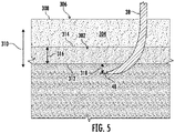
- a compaction layer 302 is present within soil 304 of a field 306.
- the compaction layer 302 is positioned below a top surface 308 of the field 306 along a vertical direction (indicated by arrow 310).
- the compaction layer 302 extends in the vertical direction 310 between a bottom surface 312 of the compaction layer 302 and a top surface 314 of the compaction layer 302.
- the compaction layer 302 has a thickness (indicated by arrow 316) extending between the bottom and top surfaces 312, 314.
- the method 200 may include generating, with the computing system, a representation of a portion of the soil within the field based on the received sensor data.
- the computing system 116 may be configured to analyze/process the received sensor data to generate a representation of a portion of the soil within the field.
- the computing system 116 may include a suitable algorithm(s) stored within its memory device(s) 122 that, when executed by the processor 120, generates the representation from the data received from the sensor 104 (e.g., the GPR data captured by the GPR sensing device 112 and the EMI data captured by the EMI sensing device 114).
- the representation of the portion of the soil within the field may correspond to any suitable data structure depicts or otherwise provides an indication of the soil structure adjacent to the field surface based on the received soil sensor data.
- the representation of the soil may correspond to a two-dimensional or three-dimensional image(s) or spatial model illustrating or depicting one or more subsurface soil layers.
- the generated three-dimensional representation may provide an indication of various parameters associated with a subsurface soil compaction layer present within the field across which the vehicle/implement 10/12 is traveling.
- such parameters may include the position or depth of the bottom and/or top surface of the compaction layer relative to the top surface of the field, the thickness of the compaction layer, and/or the like.
- the three-dimensional representation of the soil may correspond to any other suitable type of data structure, such as onedimensional representation or dataset.
- the method 200 may include determining one or more parameters associated with the compaction layer based on the sensor data received at (202).
- the computing system 116 may be configured to determine the density of the compaction layer based on the received sensor data.
- the computing system 116 may include a look-up table(s), suitable mathematical formula, and/or an algorithm(s) stored within its memory device(s) 122 that correlates the received sensor data to the density(ies) of the compaction layer.
- the method 200 may include determining, with computing system, the position of a bottom surface of the compaction layer based on the generated representation. More specifically, in several embodiments, the computing system 116 may be configured to analyze the generated representation of the soil to determine the position of the bottom surface of the compaction layer (e.g., the depth or distance of the bottom surface of the compaction layer below the top surface of the field in the vertical direction). As such, the computing system 116 may include a suitable algorithm(s) stored within its memory device(s) 122 that, when executed by the processor 120, allows the position of the bottom surface of the compaction layer to be identified from the representation of the soil. As will be described below, the determined position of the bottom surface of the compaction layer may be used to control the penetration depths of the ground-penetrating tools (e.g., the shanks 38) of the implement 10.
- the ground-penetrating tools e.g., the shanks 38
- the method 200 may further include geo-locating the determined position of the bottom surface of the compaction layer within the field. More specifically, as the vehicle/implement 10/12 travels across the field, the computing system 116 may be configured to receive location data (e.g., coordinates) from the location sensor 102 (e.g., via the communicative link 118). Based on the known dimensional configuration and/or relative positioning between the soil sensor 104 and the location sensor 102, the computing system 116 may geo-locate each determination of the position of the bottom surface of the compaction layer within the field. For example, in one embodiment, the coordinates derived from the location sensor 102 and the compaction layer bottom surface determinations may both be time-stamped.
- location data e.g., coordinates
- the time-stamped data may allow the compaction layer bottom surface determinations to be matched or correlated to a corresponding set of location coordinates received or derived from the location sensor 102.
- the computing system 116 may be configured to generate a field map identifying the position of the bottom surface of the compaction layer at one or more locations within the field.
- the method 200 may include determining one or more parameters associated with the compaction layer based on the representation of the soil generated at (204).
- the computing system 116 may be configured to analyze representation to the determine the thickness of the compaction layer (i.e., the distance between the bottom and top surfaces of the compaction layer in the vertical direction).
- the method 200 may include controlling, with computing system, the penetration depth of a ground-penetrating tool of the agricultural implement based on the determined position of the bottom surface of the compaction layer. More specifically, the computing system 116 may be configured to control the penetration depth(s) of one or more ground-penetrating tools of the implement 10 (e.g., the shanks 38) based on position of the bottom surface of the compaction layer determined at (206). For example, in some embodiments, the computing system 116 may transmit control signals to the ground-penetrating tool actuator(s) 106. The control signals may, in turn, instruct the actuators 106 to adjust the penetration depths of the tip(s) of the corresponding ground-penetrating tool(s).
- the computing system 116 may transmit control signals to the ground-penetrating tool actuator(s) 106. The control signals may, in turn, instruct the actuators 106 to adjust the penetration depths of the tip(s) of the corresponding ground-penetrating tool(s).
- the method 200 may include controlling the penetration depth(s) of the ground-penetrating tool(s) such that the tip(s) of the tool(s) is positioned below the bottom surface of the compaction layer in the vertical direction.
- the computing system 116 may be configured to control the operation of the ground-penetrating tool actuator(s) 106 such that the tip(s) of the tool(s) is maintained below the bottom surface of the compaction layer.
- the method 200 may include controlling the penetration depth(s) of the ground-penetrating tool(s) such that the tip(s) of the ground-penetrating tool(s) is maintained at a selected distance below the bottom surface of the compaction layer in the vertical direction. More specifically, in such embodiments, as the vehicle/implement 10/12 travels across the field, the computing system 116 may be configured to control the operation of the ground-penetrating tool actuator(s) 106 such that the tip(s) of the tool(s) is positioned at a selected distance below the bottom surface of the compaction layer. For example, as shown in FIG.
- the penetration depth of the tip 48 of the shank 38 is maintained at a selected distance (indicated by arrow 318) below the bottom surface 312 of the compaction layer 318 in the vertical direction 310.
- maintaining the ground-penetrating tool(s) at the selected distance below the bottom surface of the compaction layer 318 may generally improve the fracturing of the compaction layer.
- the method 200 may include determining the selected distance based one or more parameters associated with the compaction layer. More specifically, as described above, the computing system 116 may determine the position of the bottom surface of the compaction layer, the thickness of the compaction layer, and/or the density of the compaction layer. In this respect, the computing system 116 may determine the selected distance based on the position of the bottom surface of the compaction layer, the thickness of the compaction layer, the density of the compaction layer, the type of soil within the field, and/or the moisture content of the soil within the field.
- the computing system 116 may include a look-up table(s), suitable mathematical formula, and/or an algorithm(s) stored within its memory device(s) 122 that correlates the compaction layer parameter(s) to the selected distance(s).
- the selected distance may be determined based on any other suitable parameter(s) associated with the compaction layer.
- Controlling the penetration depth(s) of the ground-penetrating tool(s) based on the position of the bottom surface of the compaction layer generally improves fracturing of the compaction layer. More specifically, thicker, denser, and/or deeper compaction layers generally require the tip(s) of the tool(s) to be position farther below the bottom surface of the compaction layer to fully fracture the compaction layer.
- the selected distance between the tool(s) and the bottom surface of the compaction layer may be determined based on one or more parameters associated with the compaction layer.
- the ground-penetrating tool(s) can more fully fracture the compaction layer than when the tool(s) simply penetrate into the compaction layer.
- maintaining the tip(s) of the ground-penetrating tool(s) at the selected distance below the bottom surface of the compaction layer allows for full fracturing of the compaction without the large an unnecessary increase in draft load associated with sinking the tool(s) into the soil well below the depth of the compaction layer.
- the computing system 116 may control the operation of the ground-penetrating tool actuator(s) 106 such that the tip(s) of the tool(s) is positioned at a predetermined depth below the top surface of the field.
- the predetermined depth may be selected to fracture the soil within the seedbed of field but is generally less than the typical depths of the bottom surface of the compaction layer. Such positioning of the tool(s) when no compaction layer is present may reduce the draft load on the vehicle 10.
- the steps of the method 200 are performed by the computing system 116 upon loading and executing software code or instructions which are tangibly stored on a tangible computer readable medium, such as on a magnetic medium, e.g., a computer hard drive, an optical medium, e.g., an optical disc, solid-state memory, e.g., flash memory, or other storage media known in the art.
- a tangible computer readable medium such as on a magnetic medium, e.g., a computer hard drive, an optical medium, e.g., an optical disc, solid-state memory, e.g., flash memory, or other storage media known in the art.
- any of the functionality performed by the computing system 116 described herein, such as the method 200 is implemented in software code or instructions which are tangibly stored on a tangible computer readable medium.
- the computing system 116 loads the software code or instructions via a direct interface with the computer readable medium or via a wired and/or wireless network.
- the computing system 116 may perform any of the functionality
- software code or “code” used herein refers to any instructions or set of instructions that influence the operation of a computer or controller. They may exist in a computer-executable form, such as machine code, which is the set of instructions and data directly executed by a computer's central processing unit or by a controller, a human-understandable form, such as source code, which may be compiled in order to be executed by a computer's central processing unit or by a controller, or an intermediate form, such as object code, which is produced by a compiler.
- the term "software code” or “code” also includes any human-understandable computer instructions or set of instructions, e.g., a script, that may be executed on the fly with the aid of an interpreter executed by a computer's central processing unit or by a controller.
Landscapes
- Life Sciences & Earth Sciences (AREA)
- Engineering & Computer Science (AREA)
- Mechanical Engineering (AREA)
- Soil Sciences (AREA)
- Environmental Sciences (AREA)
- Zoology (AREA)
- Soil Working Implements (AREA)
Abstract
Description
- The present disclosure generally relates to agricultural implements and, more particularly, to systems and methods for controlling the operation of an agricultural implement based on compaction layer position.
- It is well known that, to attain the best agricultural performance from a piece of land, a farmer must cultivate the soil, typically through a tillage operation. Common tillage operations include plowing, harrowing, and sub-soiling. Modern farmers perform these tillage operations by pulling a tillage implement behind an agricultural work vehicle, such as a tractor. Depending on the crop selection and the soil conditions, a farmer may need to perform several tillage operations at different times over a crop cycle to properly cultivate the land to suit the crop choice.
- When performing certain tillage operations, it is generally desirable to break up any layers of subsurface soil that have been compacted (e.g., due to vehicle traffic, ponding, and/or the like). As such, during such tillage operations, shanks or other ground-penetrating tools supported on the tillage implement are pulled through the soil to fracture the compaction layer. However, the depth of the compaction layer may vary throughout the field. In this respect, systems have been developed that allow compaction layers to be detected and the penetration depths of the shanks or other tools to be adjusted accordingly. While such systems work well, further improvements are needed.
- Accordingly, an improved system and method for controlling the operation of an agricultural implement would be welcomed in the technology. In particular, a system and method for controlling the operation of an agricultural implement that provides improved fracturing of subsurface soil compaction layers would be welcomed in the technology.
- Aspects and advantages of the technology will be set forth in part in the following description, or may be obvious from the description, or may be learned through practice of the technology.
- In one aspect, the present subject matter is directed to a system for controlling an operation of an agricultural implement. The system includes a ground-penetrating tool configured to penetrate soil within a field to a penetration depth. Furthermore, the system includes a sensor configured to capture data indicative of a compaction layer within the field as the agricultural implement travels across the field. The compaction layer, in turn, extends in a vertical direction between a bottom surface of the compaction layer and a top surface of the compaction layer. Additionally, the system includes a computing system communicatively coupled to the sensor. In this respect, the computing system is configured to generate a representation of a portion of the soil within the field based on the data captured by the sensor. Moreover, the computing system is configured to determine a position of the bottom surface of the compaction layer based on the generated representation. In addition, the computing system is configured to control the penetration depth of the ground-penetrating tool based on the determined position of the bottom surface of the compaction layer.
- When controlling the penetration depth of the ground-penetrating tool, the computing system may be configured to control the penetration depth of the ground-penetrating tool such that a tip of the ground-penetrating tool is positioned below the bottom surface of the compaction layer in the vertical direction.
- When controlling the penetration depth of the ground-penetrating tool, the computing system may be configured to control the penetration depth of the ground-penetrating tool such that the tip of the ground-penetrating tool is maintained at a selected distance below the bottom surface of the compaction layer in the vertical direction.
- The computing system may be further configured to determine the selected distance based on the position of the bottom surface of the compaction layer.
- The computing system may be further configured to:
- determine a thickness of the compaction layer extending between the bottom surface of the compaction layer and the top surface of the compaction layer based on the generated representation; and
- determine the selected distance based on the thickness of the bottom surface of the compaction layer.
- The computing system may be further configured to:
- determine a density of the compaction layer based on the data captured by the sensor; and
- determine the selected distance based on the density of the compaction layer.
- The computing system may be further configured to determine the selected distance based on a type of the soil within the field or a moisture content of the soil within the field.
- The sensor may comprise a non-contact-based sensor.
- The sensor may comprise a ground-penetrating radar sensing device and an electromagnetic induction sensing device.
- The computing system may be further configured to generate a field map identifying the position of the bottom surface of the compaction layer at one or more locations within the field.
- The ground-penetrating tool may comprise a shank.
- In another aspect, the present subject matter is directed to a method for controlling an operation of an agricultural implement. The agricultural implement, in turn, includes a ground-penetrating tool configured to penetrate soil within a field to a penetration depth. The method includes receiving, with a computing system, sensor data indicative of a compaction layer within the field as the agricultural implement travels across the field. The compaction layer, in turn, extends in a vertical direction between a bottom surface of the compaction layer and a top surface of the compaction layer. Furthermore, the method includes generating, with the computing system, a representation of a portion of the soil within the field based on the received sensor data. Additionally, the method includes determining, with computing system, a position of the bottom surface of the compaction layer based on the generated representation. Moreover, the method includes controlling, with computing system, the penetration depth of the ground-penetrating tool based on the determined position of the bottom surface of the compaction layer.
- Controlling the penetration depth of the ground-penetrating tool may comprise controlling, with the computing system, the penetration depth of the ground-penetrating tool such that a tip of the ground-penetrating tool is positioned below the bottom surface of the compaction layer in the vertical direction.
- Controlling the penetration depth of the ground-penetrating tool may comprise controlling, with the computing system, the penetration depth of the ground-penetrating tool such that the tip of the ground-penetrating tool is maintained at a selected distance below the bottom surface of the compaction layer in the vertical direction.
- The method may further comprise: determining, with the computing system, the selected distance based on the position of the bottom surface of the compaction layer.
- The method may further comprise:
- determining, with the computing system, a thickness of the compaction layer extending between the bottom surface of the compaction layer and the top surface of the compaction layer based on the generated representation; and
- determining, with the computing system, the selected distance based on the thickness of the bottom surface of the compaction layer.
- The method may further comprise:
- determining, with the computing system, a density of the compaction layer based on the received sensor data; and
- determining, with the computing system, the selected distance based on the density of the compaction layer.
- The method may further comprise:
determining, with the computing system, the selected distance based on a type of the soil within the field or a moisture content of the soil within the field. - The sensor data may comprise a non-contact-based sensor data.
- The method may further comprise:
generating, with the computing system, a field map identifying the position of the bottom surface of the compaction layer at one or more locations within the field. - These and other features, aspects and advantages of the present technology will become better understood with reference to the following description and appended claims. The accompanying drawings, which are incorporated in and constitute a part of this specification, illustrate embodiments of the technology and, together with the description, serve to explain the principles of the technology.
- A full and enabling disclosure of the present technology, including the best mode thereof, directed to one of ordinary skill in the art, is set forth in the specification, which makes reference to the appended figures, in which:
-
FIG. 1 illustrates a perspective view of one embodiment of a work vehicle towing an implement in accordance with aspects of the present subject matter; -
FIG. 2 illustrates a side view of one embodiment of a shank of an agricultural implement in accordance with aspects of the present subject matter; -
FIG. 3 illustrates a schematic view of one embodiment of a system for controlling the operation of an agricultural implement in accordance with aspects of the present subject matter; -
FIG. 4 illustrates a flow diagram of one embodiment of a method for controlling the operation of an agricultural implement in accordance with aspects of the present subject matter; and -
FIG. 5 illustrates a cross-sectional side view of one embodiment of a ground-penetrating tool of an agricultural implement penetrating into the soil of the field, particularly illustrating the position of the tool relative to a bottom surface of a compaction layer within the field. - Repeat use of reference characters in the present specification and drawings is intended to represent the same or analogous features or elements of the present technology.
- Reference now will be made in detail to embodiments of the invention, one or more examples of which are illustrated in the drawings. Each example is provided by way of explanation of the invention, not limitation of the invention. In fact, it will be apparent to those skilled in the art that various modifications and variations can be made in the present invention without departing from the scope or spirit of the invention. For instance, features illustrated or described as part of one embodiment can be used with another embodiment to yield a still further embodiment. Thus, it is intended that the present invention covers such modifications and variations as come within the scope of the appended claims and their equivalents.
- In general, the present subject matter is directed to systems and methods for controlling the operation of an agricultural implement. Specifically, the system may include a sensor configured to capture data indicative of a compaction layer present within the field as the agricultural implement travels across the field. The compaction layer may, in turn, extend in the vertical direction between a bottom surface of the compaction layer and a top surface of the compaction layer. For example, in one embodiment, the sensor may include a ground-penetrating radar (GPR) sensing device and an electromagnetic induction (EMI) sensing device.
- In several embodiments, a computing system may be configured to control the penetration depth(s) of one or more ground-penetrating tools of the agricultural implement based on the position of the bottom surface of the compaction layer. As the implement travels across the field, the computing system may generate a representation of a portion of the soil within the field based on the data captured by the sensor. Furthermore, the computing system may determine the position of the bottom surface of the compaction layer based on the generated representation. Thereafter, the computing system may control the penetration depth(s) of the ground-penetrating tool(s) such that the tip(s) of the tool(s) is positioned below the bottom surface of the compaction layer. Specifically, in some embodiments, the computing system may control the penetration depth(s) of the ground-penetrating tool(s) such that the tip(s) of the tool(s) is maintained at a selected distance below the bottom surface of the compaction layer.
- Controlling the penetration depth(s) of the ground-penetrating tool(s) based on the position of the bottom surface of the compaction layer generally improves fracturing of the compaction layer. As will be described below, the selected distance between the tool(s) and the bottom surface of the compaction layer may be determined based on one or more parameters associated with the compaction layer, such as the position of the bottom surface of the compaction layer, the thickness of the compaction layer, the density of the compaction layer, the type of soil within the field, and/or the moisture content of the soil within the field. In this respect, by maintaining the tip(s) of the ground-penetrating tool(s) at the selected distance below the bottom surface of the compaction layer, the ground-penetrating tool(s) can more fully fracture the compaction layer than when the tool(s) simply penetrate into the compaction layer. Moreover, maintaining the tip(s) of the ground-penetrating tool(s) at the selected distance below the bottom surface of the compaction layer allows for full fracturing of the compaction without the large an unnecessary increase in draft load associated with sinking the tool(s) into the soil well below the depth of the compaction layer.
- Referring now to the drawings,
FIG. 1 illustrates a perspective view of one embodiment of awork vehicle 10 and an associated agricultural implement 12 in accordance with aspects of the present subject matter. In general, thework vehicle 10 may be configured to tow the implement 12 across a field in a direction of travel (e indicated by arrow 14). As such, in one embodiment, thework vehicle 10 may be configured as an agricultural tractor and the implement 12 may be configured as a tillage implement. However, in other embodiments, thework vehicle 10 may be configured as any other suitable work vehicle. Similarly, the implement 12 may be configured as any other suitable agricultural implement. - As shown, the
work vehicle 10 may include a pair offront track assemblies 16, a pair orrear track assemblies 18, and a frame orchassis 20 coupled to and supported by thetrack assemblies cab 22 may be supported by a portion of thechassis 20 and may house various input devices (e.g., a user interface) for permitting an operator to control the operation of one or more components of thework vehicle 10 and/or one or more components of the implement 12. - Additionally, as shown in
FIG. 1 , the implement 12 may generally include aframe 28 configured to be towed by thevehicle 10 via a pull hitch ortow bar 30 in the direction oftravel 14. In general, theframe 28 may include a plurality ofstructural frame members 32, such as beams, bars, and/or the like, configured to support or couple to a plurality of components. As such, theframe 28 may be configured to support a plurality of ground-engaging and/or ground-penetrating tools, such as a plurality of shanks, disk blades, leveling blades, basket assemblies, tines, spikes, and/or the like. In one embodiment, the various ground-engaging and/or ground-penetrating tools may be configured to perform a tillage operation or any other suitable ground-engaging operation on the field across which the implement 12 is being towed. For example, in the illustrated embodiment, theframe 28 is configured to supportvarious gangs 34 ofdisk blades 36, a plurality of ground-penetratingshanks 38, a plurality of levelingblades 40, and a plurality of crumbier wheels orbasket assemblies 42. However, in alternative embodiments, theframe 28 may be configured to support any other suitable ground-engaging tool(s), ground-penetrating tool(s), or combinations of such tools. - Moreover, a
location sensor 102 may be provided in operative association with thevehicle 10 and/or the implement 12. For instance, as shown inFIG. 1 , thelocation sensor 102 is installed on or within thevehicle 10. However, in other embodiments, thelocation sensor 102 may be installed on or within the implement 12. In general, thelocation sensor 102 may be configured to determine the current location of thevehicle 10 and/or the implement 12 using a satellite navigation positioning system (e.g., a GPS system, a Galileo positioning system, the Global Navigation satellite system (GLONASS), the BeiDou Satellite Navigation and Positioning system, and/or the like). In such an embodiment, the location determined by thelocation sensor 102 may be transmitted to a computing system of thevehicle 10 and/or the implement 12 (e.g., in the form coordinates) and stored within the computing system's memory for subsequent processing and/or analysis. For instance, based on the known dimensional configuration and/or relative positioning between thevehicle 10 and the implement 12, the determined location from thelocation sensor 102 may be used to geo-locate the implement 12 within the field. - Furthermore, a
soil sensor 104 may be provided in operative association with thevehicle 10 and/or the implement 12. In general, thesoil sensor 104 may be configured to capture data indicative of a subsurface soil compaction layer present within the field as the vehicle/implement 10/12 travels across the field. As will be described below, the data captured by thesoil sensor 104 may be used to identify the position the bottom surface of the compaction layer. In this respect, thesoil sensor 104 may be a non-contact-based sensor installed or otherwise supported on thevehicle 10 and/or the implement 12 such that thesensor 104 has a field of view or sensor detection range directed towards a portion of the field adjacent to the vehicle/implement 10/12. For example, as shown inFIG. 1 , in one embodiment, thesoil sensor 104 may be mounted on aforward end 44 of thework vehicle 10 to capture data associated with a portion of the soil within the field disposed in front of thevehicle 10 relative to the direction oftravel 14. However, in alternative embodiments, thesoil sensor 104 may be installed at any other suitable location on thevehicle 10 and/or the implement 12. Additionally, in some embodiments, the vehicle/implement 10/12 may include more than onesoil sensor 104. - Referring now to
FIG. 2 , a side view of one embodiment of one of theshanks 38 of the implement 12 described above with reference toFIG. 1 is illustrated in accordance with aspects of the present subject matter. As indicated above, theshanks 38 may be configured to till or otherwise cultivate the soil. In this regard, one end of eachshank 38 may include atip 48 configured to penetrate the soil within the field to a penetration depth as the implement 12 is pulled across the field. The opposed end of eachshank 38 may be pivotally coupled to the implementframe 28, such as atpivot point 50. As such, eachshank 38 may be configured to pivot relative to theframe 28 in a manner that adjusts its penetration depth. In one embodiment, thevarious shanks 38 of the implement 12 may be configured as rippers. However, in alternative embodiments, theshanks 38 may be configured as chisels, sweeps, tines, or any other suitable type of shanks. Furthermore, the other shanks coupled to theframe 28 may have the same or a similar configuration to as theshank 38 shown inFIG. 2 . - In several embodiments, the implement 12 may include one or more ground-penetrating
tool actuators 106, with each actuator 106 coupled between theframe 28 and eachshank 38. In general, each actuator 106 may be configured to move or otherwise adjust the orientation or position of the correspondingshank 38 relative to the implementframe 28 in a manner that adjusts the penetration depth of theshank 38. More specifically, as shown in the illustrated embodiment, a first end of each actuator 106 (e.g., arod 108 of each actuator 106) is coupled to the correspondingshank 38, while a second end of each actuator 106 (e.g., acylinder 110 of each actuator 106) is coupled to theframe 28. As such, therod 108 of each actuator 106 may be configured to extend relative to thecorresponding cylinder 110 to pivot the correspondingshank 38 relative to theframe 28 in a first pivot direction (indicated by arrow 52), thereby increasing the penetration depth of theshank 38. Conversely, therod 108 of each actuator 106 may be configured to retract relative to thecorresponding cylinder 110 to pivot the correspondingshank 38 relative to theframe 28 in a second pivot direction (indicated by arrow 54), thereby decreasing the penetration depth of theshank 38. In the illustrated embodiment, eachactuator 106 corresponds to a fluid-driven actuator, such as a hydraulic or pneumatic cylinder. However, in alternative embodiments, each actuator 106 may correspond to any other suitable type of actuator, such as an electric linear actuator. - It should be further appreciated that the configuration of the
work vehicle 10 and the agricultural implement 12 described above and shown inFIGS. 1 and2 is provided only to place the present subject matter in an exemplary field of use. Thus, it should be appreciated that the present subject matter may be readily adaptable to any manner of agricultural machine configuration. - Referring now to
FIG. 3 , a schematic view of one embodiment of asystem 100 for controlling the operation of an agricultural implement is illustrated in accordance with aspects of the present subject matter. In general, thesystem 100 will be described herein with reference to thework vehicle 10 and the agricultural implement 12 described above with reference toFIGS. 1 and2 . However, it should be appreciated by those of ordinary skill in the art that the disclosedsystem 100 may generally be utilized with work vehicles having any other suitable vehicle configuration and/or agricultural implements having any other suitable implement configuration. - As shown in
FIG. 3 , thesystem 100 may include asoil sensor 104 provided in operative association with thevehicle 10 and/or the implement 12. In general, as mentioned above, thesoil sensor 104 may be configured to capture data indicative of a subsurface soil compaction layer present within the field as the vehicle/implement 10/12 travels across the field. As such, in several embodiments, thesoil sensor 104 may include a ground-penetrating radar (GPR)sensing device 112 and electromagnetic induction (EMI)sensing device 114. In such embodiments, theGPR sensing device 112 may be configured to capture GPR data associated with the soil present within the field of view or sensor detection range of theGPR sensing device 112. Similarly, theEMI sensing device 114 may be configured to capture EMI data associated with the soil present within the field of view or sensor detection range of theEMI sensing device 114. In this respect, the combination of GPR and EMI data may allow a three-dimensional representation of the soil to be generated (that could not be generated by GPR or EMI data alone). Such three-dimensional representation may, in turn, allow the position of the bottom surface of the compaction layer within the soil to be identified. - The
GPR sensing device 112 may correspond to any suitable sensor or sensing device configured to capture data associated with the soil within the field using radio waves. For example, theGPR sensing device 112 may be configured to emit one or more radio wave output signals directed toward a portion of the soil within its field of view or sensor detection zone. A portion of the output signal(s) may, in turn, be reflected by the subsurface compaction layer as echo signal(s). Moreover, theGPR sensing device 112 may be configured to receive the reflected echo signal(s). In this regard, the time of flight, amplitude, frequency, and/or phase of the received echo signal(s) may be used to generate the three-dimensional representation (in combination with the EMI data) and/or determine the one or more parameters associated within the compaction (e.g., density). - Moreover, the
EMI sensing device 114 may correspond to any suitable sensor or sensing device configured to capture data associated with the soil within the field using electromagnetic induction. For example, theEMI sensing device 114 may include a coil(s) or other inductor(s). In this respect, as the vehicle/implement 10/12 travels across the field, the compaction layer may induce a current within the coil. The current may, in turn, vary with the parameters of the compaction layer (e.g., position of the bottom surface, thickness, density, and/or the like). As such, the induced current may be used to generate the three-dimensional representation (in combination with the GPR data) and/or determine the one or more parameters associated within the compaction. - However, in alternative embodiments, the
soil sensor 104 may be configured as any other suitable sensor(s) or sensing device(s) configured to capture data that can be used to identify the position of the bottom surface of the compaction layer as the vehicle/implement 10/12 travels across the field. For example, in one embodiment, thesoil sensor 104 may be a contact-based sensor, such as a cone penetrometer. - In accordance with aspects of the present subject matter, the
system 100 may include acomputing system 116 communicatively coupled to one or more components of thevehicle 10, the implement 12, and/or thesystem 100 to allow the operation of such components to be electronically or automatically controlled by thecomputing system 116. For instance, thecomputing system 116 may be communicatively coupled to thelocation sensor 102 via acommunicative link 118. As such, thecomputing system 116 may be configured to receive data from thelocation sensor 102 that is indicative of the location of the vehicle/implement 10/12 within the field. Furthermore, thecomputing system 116 may be communicatively coupled to thesoil sensor 104 via thecommunicative link 118. As such, thecomputing system 116 may be configured to receive data from thesoil sensor 104 that is indicative of the compaction layer within the field as the vehicle/implement 10/12 travels across the field. Moreover, thecomputing system 116 may be communicatively coupled to the ground-penetrating tool actuator(s) 106 via thecommunicative link 118. In this respect, thecomputing system 116 may be configured to control the operation of the ground-penetrating tool actuator(s) 106 in a manner that controls the penetration depth(s) of the associated ground-penetrating tool(s) (e.g., the shanks 38). Additionally, thecomputing system 116 may be communicatively coupled to any other suitable components of thevehicle 10, the implement 12, and/or thesystem 100. - In general, the
computing system 116 may comprise one or more processor-based devices, such as a given controller or computing device or any suitable combination of controllers or computing devices. Thus, in several embodiments, thecomputing system 116 may include one or more processor(s) 120 and associated memory device(s) 122 configured to perform a variety of computerimplemented functions. As used herein, the term "processor" refers not only to integrated circuits referred to in the art as being included in a computer, but also refers to a controller, a microcontroller, a microcomputer, a programmable logic circuit (PLC), an application specific integrated circuit, and other programmable circuits. Additionally, the memory device(s) 122 of thecomputing system 116 may generally comprise memory element(s) including, but not limited to, a computer readable medium (e.g., random access memory RAM)), a computer readable non-volatile medium (e.g., a flash memory), a floppy disk, a compact disk-read only memory (CD-ROM), a magneto-optical disk (MOD), a digital versatile disk (DVD) and/or other suitable memory elements. Such memory device(s) 122 may generally be configured to store suitable computer-readable instructions that, when implemented by the processor(s) 120, configure thecomputing system 116 to perform various computerimplemented functions, such as one or more aspects of the methods and algorithms that will be described herein. In addition, thecomputing system 116 may also include various other suitable components, such as a communications circuit or module, one or more input/output channels, a data/control bus and/or the like. - The various functions of the
computing system 116 may be performed by a single processor-based device or may be distributed across any number of processor-based devices, in which instance such devices may be considered to form part of thecomputing system 116. For instance, the functions of thecomputing system 116 may be distributed across multiple application-specific controllers or computing devices, such as a vehicle controller, an implement controller, a navigation controller, and/or the like. - Referring now to
FIG. 4 , a flow diagram of one embodiment of amethod 200 for controlling an operation of an agricultural implement is illustrated in accordance with aspects of the present subject matter. In general, themethod 200 will be described herein with reference to thework vehicle 10, the agricultural implement 12, and thesystem 100 described above with reference toFIGS. 1-3 . However, it should be appreciated by those of ordinary skill in the art that the disclosedmethod 200 may generally be implemented with any work vehicles having any suitable vehicle configuration, any agricultural implements having any suitable implement configuration, and/or within any system having any suitable system configuration. In addition, althoughFIG. 4 depicts steps performed in a particular order for purposes of illustration and discussion, the methods discussed herein are not limited to any particular order or arrangement. One skilled in the art, using the disclosures provided herein, will appreciate that various steps of the methods disclosed herein can be omitted, rearranged, combined, and/or adapted in various ways without deviating from the scope of the present disclosure. - As shown in
FIG. 4 , at (202), themethod 200 may include receiving, with a computing system, sensor data indicative of a compaction layer within a field as an agricultural implement travels across the field. For example, in several embodiments, as the vehicle/implement 10/12 travels across a field to perform a tillage operation thereon, thecomputing system 116 may receive data indicative of a compaction layer within the field from the soil sensor 104 (e.g., via the communicative link 118). - In general, the compaction layer may correspond to any subsurface layer of soil that has been compacted, such as due to vehicle traffic, ponding, and/or the like. In this respect, the compaction layer may be a subsurface layer of soil having a greater density (i.e., reduced pore space) than the soil above and/or below the compaction layer. As such, the increased density of the compaction layer may impede the root growth of the crops planted within the field. For example, as shown in
FIG. 5 , acompaction layer 302 is present withinsoil 304 of afield 306. In particular, thecompaction layer 302 is positioned below atop surface 308 of thefield 306 along a vertical direction (indicated by arrow 310). Moreover, thecompaction layer 302 extends in thevertical direction 310 between abottom surface 312 of thecompaction layer 302 and atop surface 314 of thecompaction layer 302. Thus, thecompaction layer 302 has a thickness (indicated by arrow 316) extending between the bottom andtop surfaces - Additionally, as shown in
FIG. 4 , at (204), themethod 200 may include generating, with the computing system, a representation of a portion of the soil within the field based on the received sensor data. Specifically, in several embodiments, thecomputing system 116 may be configured to analyze/process the received sensor data to generate a representation of a portion of the soil within the field. As such, thecomputing system 116 may include a suitable algorithm(s) stored within its memory device(s) 122 that, when executed by theprocessor 120, generates the representation from the data received from the sensor 104 (e.g., the GPR data captured by theGPR sensing device 112 and the EMI data captured by the EMI sensing device 114). - The representation of the portion of the soil within the field may correspond to any suitable data structure depicts or otherwise provides an indication of the soil structure adjacent to the field surface based on the received soil sensor data. For example, in several embodiments, the representation of the soil may correspond to a two-dimensional or three-dimensional image(s) or spatial model illustrating or depicting one or more subsurface soil layers. In this respect, the generated three-dimensional representation may provide an indication of various parameters associated with a subsurface soil compaction layer present within the field across which the vehicle/implement 10/12 is traveling. For example, such parameters may include the position or depth of the bottom and/or top surface of the compaction layer relative to the top surface of the field, the thickness of the compaction layer, and/or the like. However, in alternative embodiments, the three-dimensional representation of the soil may correspond to any other suitable type of data structure, such as onedimensional representation or dataset.
- In addition, at (204), the
method 200 may include determining one or more parameters associated with the compaction layer based on the sensor data received at (202). For example, in one embodiment, thecomputing system 116 may be configured to determine the density of the compaction layer based on the received sensor data. In such an embodiment, thecomputing system 116 may include a look-up table(s), suitable mathematical formula, and/or an algorithm(s) stored within its memory device(s) 122 that correlates the received sensor data to the density(ies) of the compaction layer. - Moreover, at (206), the
method 200 may include determining, with computing system, the position of a bottom surface of the compaction layer based on the generated representation. More specifically, in several embodiments, thecomputing system 116 may be configured to analyze the generated representation of the soil to determine the position of the bottom surface of the compaction layer (e.g., the depth or distance of the bottom surface of the compaction layer below the top surface of the field in the vertical direction). As such, thecomputing system 116 may include a suitable algorithm(s) stored within its memory device(s) 122 that, when executed by theprocessor 120, allows the position of the bottom surface of the compaction layer to be identified from the representation of the soil. As will be described below, the determined position of the bottom surface of the compaction layer may be used to control the penetration depths of the ground-penetrating tools (e.g., the shanks 38) of the implement 10. - Furthermore, in some embodiments, at (206), the
method 200 may further include geo-locating the determined position of the bottom surface of the compaction layer within the field. More specifically, as the vehicle/implement 10/12 travels across the field, thecomputing system 116 may be configured to receive location data (e.g., coordinates) from the location sensor 102 (e.g., via the communicative link 118). Based on the known dimensional configuration and/or relative positioning between thesoil sensor 104 and thelocation sensor 102, thecomputing system 116 may geo-locate each determination of the position of the bottom surface of the compaction layer within the field. For example, in one embodiment, the coordinates derived from thelocation sensor 102 and the compaction layer bottom surface determinations may both be time-stamped. In such an embodiment, the time-stamped data may allow the compaction layer bottom surface determinations to be matched or correlated to a corresponding set of location coordinates received or derived from thelocation sensor 102. Additionally, in some embodiments, thecomputing system 116 may be configured to generate a field map identifying the position of the bottom surface of the compaction layer at one or more locations within the field. - Additionally, in one embodiment, at (206), the
method 200 may include determining one or more parameters associated with the compaction layer based on the representation of the soil generated at (204). For example, in one embodiment, thecomputing system 116 may be configured to analyze representation to the determine the thickness of the compaction layer (i.e., the distance between the bottom and top surfaces of the compaction layer in the vertical direction). - Moreover, at (208), the
method 200 may include controlling, with computing system, the penetration depth of a ground-penetrating tool of the agricultural implement based on the determined position of the bottom surface of the compaction layer. More specifically, thecomputing system 116 may be configured to control the penetration depth(s) of one or more ground-penetrating tools of the implement 10 (e.g., the shanks 38) based on position of the bottom surface of the compaction layer determined at (206). For example, in some embodiments, thecomputing system 116 may transmit control signals to the ground-penetrating tool actuator(s) 106. The control signals may, in turn, instruct theactuators 106 to adjust the penetration depths of the tip(s) of the corresponding ground-penetrating tool(s). - In several embodiments, at (208), the
method 200 may include controlling the penetration depth(s) of the ground-penetrating tool(s) such that the tip(s) of the tool(s) is positioned below the bottom surface of the compaction layer in the vertical direction. For example, in such embodiments, as the vehicle/implement 10/12 travels across the field, thecomputing system 116 may be configured to control the operation of the ground-penetrating tool actuator(s) 106 such that the tip(s) of the tool(s) is maintained below the bottom surface of the compaction layer. - Furthermore, in some embodiments, at (208), the
method 200 may include controlling the penetration depth(s) of the ground-penetrating tool(s) such that the tip(s) of the ground-penetrating tool(s) is maintained at a selected distance below the bottom surface of the compaction layer in the vertical direction. More specifically, in such embodiments, as the vehicle/implement 10/12 travels across the field, thecomputing system 116 may be configured to control the operation of the ground-penetrating tool actuator(s) 106 such that the tip(s) of the tool(s) is positioned at a selected distance below the bottom surface of the compaction layer. For example, as shown inFIG. 5 , the penetration depth of thetip 48 of theshank 38 is maintained at a selected distance (indicated by arrow 318) below thebottom surface 312 of thecompaction layer 318 in thevertical direction 310. As will be described below, maintaining the ground-penetrating tool(s) at the selected distance below the bottom surface of thecompaction layer 318 may generally improve the fracturing of the compaction layer. - In addition, in some embodiments, at (208), the
method 200 may include determining the selected distance based one or more parameters associated with the compaction layer. More specifically, as described above, thecomputing system 116 may determine the position of the bottom surface of the compaction layer, the thickness of the compaction layer, and/or the density of the compaction layer. In this respect, thecomputing system 116 may determine the selected distance based on the position of the bottom surface of the compaction layer, the thickness of the compaction layer, the density of the compaction layer, the type of soil within the field, and/or the moisture content of the soil within the field. For example, thecomputing system 116 may include a look-up table(s), suitable mathematical formula, and/or an algorithm(s) stored within its memory device(s) 122 that correlates the compaction layer parameter(s) to the selected distance(s). However, in alternative embodiments, the selected distance may be determined based on any other suitable parameter(s) associated with the compaction layer. - Controlling the penetration depth(s) of the ground-penetrating tool(s) based on the position of the bottom surface of the compaction layer generally improves fracturing of the compaction layer. More specifically, thicker, denser, and/or deeper compaction layers generally require the tip(s) of the tool(s) to be position farther below the bottom surface of the compaction layer to fully fracture the compaction layer. In this respect, as described above, the selected distance between the tool(s) and the bottom surface of the compaction layer may be determined based on one or more parameters associated with the compaction layer. In this respect, by maintaining the tip(s) of the ground-penetrating tool(s) at a selected distance below the bottom surface of the compaction layer, the ground-penetrating tool(s) can more fully fracture the compaction layer than when the tool(s) simply penetrate into the compaction layer. Moreover, maintaining the tip(s) of the ground-penetrating tool(s) at the selected distance below the bottom surface of the compaction layer allows for full fracturing of the compaction without the large an unnecessary increase in draft load associated with sinking the tool(s) into the soil well below the depth of the compaction layer.
- However, when the position of the bottom surface of the compaction layer cannot be determined at (206) (thereby indicating that no compaction layer is present within the field at the current location the vehicle/implement 10/12), the
computing system 116 may control the operation of the ground-penetrating tool actuator(s) 106 such that the tip(s) of the tool(s) is positioned at a predetermined depth below the top surface of the field. The predetermined depth may be selected to fracture the soil within the seedbed of field but is generally less than the typical depths of the bottom surface of the compaction layer. Such positioning of the tool(s) when no compaction layer is present may reduce the draft load on thevehicle 10. - It is to be understood that the steps of the
method 200 are performed by thecomputing system 116 upon loading and executing software code or instructions which are tangibly stored on a tangible computer readable medium, such as on a magnetic medium, e.g., a computer hard drive, an optical medium, e.g., an optical disc, solid-state memory, e.g., flash memory, or other storage media known in the art. Thus, any of the functionality performed by thecomputing system 116 described herein, such as themethod 200, is implemented in software code or instructions which are tangibly stored on a tangible computer readable medium. Thecomputing system 116 loads the software code or instructions via a direct interface with the computer readable medium or via a wired and/or wireless network. Upon loading and executing such software code or instructions by thecomputing system 116, thecomputing system 116 may perform any of the functionality of thecomputing system 116 described herein, including any steps of themethod 200 described herein. - The term "software code" or "code" used herein refers to any instructions or set of instructions that influence the operation of a computer or controller. They may exist in a computer-executable form, such as machine code, which is the set of instructions and data directly executed by a computer's central processing unit or by a controller, a human-understandable form, such as source code, which may be compiled in order to be executed by a computer's central processing unit or by a controller, or an intermediate form, such as object code, which is produced by a compiler. As used herein, the term "software code" or "code" also includes any human-understandable computer instructions or set of instructions, e.g., a script, that may be executed on the fly with the aid of an interpreter executed by a computer's central processing unit or by a controller.
- This written description uses examples to disclose the technology, including the best mode, and also to enable any person skilled in the art to practice the technology, including making and using any devices or systems and performing any incorporated methods. The patentable scope of the technology is defined by the claims, and may include other examples that occur to those skilled in the art. Such other examples are intended to be within the scope of the claims if they include structural elements that do not differ from the literal language of the claims, or if they include equivalent structural elements with insubstantial differences from the literal language of the claims.
Claims (15)
- A system (100) for controlling an operation of an agricultural implement (12), the system (100) comprising a ground-penetrating tool (36, 38, 40) configured to penetrate soil within a field to a penetration depth and a sensor (104) configured to capture data indicative of a compaction layer within the field as the agricultural implement (12) travels across the field, the compaction layer extending in a vertical direction between a bottom surface of the compaction layer and a top surface of the compaction layer, the system (100) further comprising a computing system (116) communicatively coupled to the sensor (104), the system (100) characterized by the computing system (116) configured to:generate a representation of a portion of the soil within the field based on the data captured by the sensor (104);determine a position of the bottom surface of the compaction layer based on the generated representation; andcontrol the penetration depth of the ground-penetrating tool (36, 38, 40) based on the determined position of the bottom surface of the compaction layer.
- The system (100) as in claim 1, wherein, when controlling the penetration depth of the ground-penetrating tool (36, 38, 40), the computing system (116) is configured to control the penetration depth of the ground-penetrating tool (36, 38, 40) such that a tip (48) of the ground-penetrating tool (36, 38, 40) is positioned below the bottom surface of the compaction layer in the vertical direction.
- The system (100) as in any preceding claim, wherein, when controlling the penetration depth of the ground-penetrating tool (36, 38, 40), the computing system (116) is configured to control the penetration depth of the ground-penetrating tool (36, 38, 40) such that the tip (48) of the ground-penetrating tool (36, 38, 40) is maintained at a selected distance below the bottom surface of the compaction layer in the vertical direction.
- The system (100) as in any preceding claim, wherein the computing system (116) is further configured to determine the selected distance based on the position of the bottom surface of the compaction layer.
- The system (100) as in any preceding claim, wherein the computing system (116) is further configured to:determine a thickness of the compaction layer extending between the bottom surface of the compaction layer and the top surface of the compaction layer based on the generated representation; anddetermine the selected distance based on the thickness of the bottom surface of the compaction layer.
- The system (100) as in any preceding claim, wherein the computing system (116) is further configured to:determine a density of the compaction layer based on the data captured by the sensor (104); anddetermine the selected distance based on the density of the compaction layer.
- The system (100) as in any preceding claim, wherein the computing system (116) is further configured to determine the selected distance based on a type of the soil within the field or a moisture content of the soil within the field.
- The system (100) as in any preceding claim, wherein the sensor (104) comprises a non-contact-based sensor (104).
- The system (100) of claim 8, wherein the sensor (104) comprises a ground-penetrating radar sensing device (112) and an electromagnetic induction sensing device (114).
- The system (100) as in any preceding claim, wherein the computing system (116) is further configured to generate a field map identifying the position of the bottom surface of the compaction layer at one or more locations within the field.
- The system (100) as in any preceding claim, wherein the ground-penetrating tool (36, 38, 40) comprises a shank (38).
- A method (200) for controlling an operation of an agricultural implement (12), the agricultural implement (12) including a ground-penetrating tool (36, 38, 40) configured to penetrate soil within a field to a penetration depth, the method (200) comprising receiving, with a computing system (116), sensor (104) data indicative of a compaction layer within the field as the agricultural implement (12) travels across the field, the compaction layer extending in a vertical direction between a bottom surface of the compaction layer and a top surface of the compaction layer, the method (200) characterized by:generating, with the computing system (116), a representation of a portion of the soil within the field based on the received sensor data;determining, with computing system (116), a position of the bottom surface of the compaction layer based on the generated representation; andcontrolling, with computing system (116), the penetration depth of the ground-penetrating tool (36, 38, 40) based on the determined position of the bottom surface of the compaction layer.
- The method (200) as in claim 12, wherein controlling the penetration depth of the ground-penetrating tool (36, 38, 40) comprises controlling, with the computing system (116), the penetration depth of the ground-penetrating tool (36, 38, 40) such that a tip (48) of the ground-penetrating tool (36, 38, 40) is positioned below the bottom surface of the compaction layer in the vertical direction.
- The method (200) as in any of claims 12 or 13, wherein controlling the penetration depth of the ground-penetrating tool (36, 38, 40) comprises controlling, with the computing system (116), the penetration depth of the ground-penetrating tool (36, 38, 40) such that the tip (48) of the ground-penetrating tool (36, 38, 40) is maintained at a selected distance below the bottom surface of the compaction layer in the vertical direction.
- The method (200) as in any of claims 12 through 14, further comprising:
determining, with the computing system (116), the selected distance based on the position of the bottom surface of the compaction layer.
Applications Claiming Priority (1)
| Application Number | Priority Date | Filing Date | Title |
|---|---|---|---|
| US17/162,175 US12185650B2 (en) | 2021-01-29 | 2021-01-29 | System and method for controlling the operation of an agricultural implement based on compaction layer position |
Publications (1)
| Publication Number | Publication Date |
|---|---|
| EP4035514A1 true EP4035514A1 (en) | 2022-08-03 |
Family
ID=80122331
Family Applications (1)
| Application Number | Title | Priority Date | Filing Date |
|---|---|---|---|
| EP22154085.9A Pending EP4035514A1 (en) | 2021-01-29 | 2022-01-28 | System and method for controlling the operation of an agricultural implement based on compaction layer position |
Country Status (2)
| Country | Link |
|---|---|
| US (1) | US12185650B2 (en) |
| EP (1) | EP4035514A1 (en) |
Families Citing this family (1)
| Publication number | Priority date | Publication date | Assignee | Title |
|---|---|---|---|---|
| US20240172580A1 (en) * | 2022-11-30 | 2024-05-30 | Cnh Industrial America Llc | System and method for automatically leveling an agricultural implement using forward-looking sensor data |
Citations (3)
| Publication number | Priority date | Publication date | Assignee | Title |
|---|---|---|---|---|
| US20180160613A1 (en) * | 2016-12-12 | 2018-06-14 | Cnh Industrial Canada, Ltd. | Agricultural implement with automatic shank depth control |
| WO2019158454A1 (en) * | 2018-02-14 | 2019-08-22 | Geoprospectors Gmbh | Apparatus and method for soil cultivation |
| US20190320574A1 (en) * | 2018-04-18 | 2019-10-24 | Cnh Industrial America Llc | System for creating soil compaction maps and associated methods for controlling the operation of a tillage implement |
Family Cites Families (11)
| Publication number | Priority date | Publication date | Assignee | Title |
|---|---|---|---|---|
| US8827001B2 (en) | 2012-01-17 | 2014-09-09 | Cnh Industrial America Llc | Soil monitoring system |
| US10262413B2 (en) | 2015-05-08 | 2019-04-16 | The Climate Corporation | Work layer imaging and analysis for implement monitoring, control and operator feedback |
| WO2017049186A1 (en) | 2015-09-18 | 2017-03-23 | Precision Planting Llc | Apparatus, system and method for monitoring soil criteria during tillage operations and control of tillage tools |
| BR102015030677B1 (en) | 2015-12-08 | 2021-09-08 | Stara S/a. Industria De Implementos Agrícolas | SOIL RESISTANCE READING MECHANISM AND SOIL PREPARATION EQUIPMENT CONTROL IN REAL TIME |
| EP3534685B1 (en) * | 2016-11-07 | 2025-10-01 | Climate LLC | Work layer imaging and analysis for implement monitoring, control and operator feedback |
| US10827665B2 (en) | 2018-09-19 | 2020-11-10 | Deere & Company | Tool height control for ground engaging tools |
| US11064645B2 (en) | 2018-10-16 | 2021-07-20 | Cnh Industrial America Llc | System and method for controlling operation of a work vehicle towing an agricultural implement |
| US11001380B2 (en) | 2019-02-11 | 2021-05-11 | Cnh Industrial Canada, Ltd. | Methods for acquiring field condition data |
| US11785878B2 (en) | 2019-05-28 | 2023-10-17 | GroundTruth Ag, Inc. | Systems and methods for tillage optimization using non-invasive multimodal sensors |
| US11944029B2 (en) | 2020-07-22 | 2024-04-02 | GroundTruth Ag, Inc. | Systems and methods for diagnosing soil characteristics and subterranean plant characteristics |
| US20240008389A1 (en) | 2020-10-02 | 2024-01-11 | GroundTruth Ag, Inc. | Systems, methods and devices for using machine learning to optimize crop residue management |
-
2021
- 2021-01-29 US US17/162,175 patent/US12185650B2/en active Active
-
2022
- 2022-01-28 EP EP22154085.9A patent/EP4035514A1/en active Pending
Patent Citations (3)
| Publication number | Priority date | Publication date | Assignee | Title |
|---|---|---|---|---|
| US20180160613A1 (en) * | 2016-12-12 | 2018-06-14 | Cnh Industrial Canada, Ltd. | Agricultural implement with automatic shank depth control |
| WO2019158454A1 (en) * | 2018-02-14 | 2019-08-22 | Geoprospectors Gmbh | Apparatus and method for soil cultivation |
| US20190320574A1 (en) * | 2018-04-18 | 2019-10-24 | Cnh Industrial America Llc | System for creating soil compaction maps and associated methods for controlling the operation of a tillage implement |
Also Published As
| Publication number | Publication date |
|---|---|
| US12185650B2 (en) | 2025-01-07 |
| US20220240430A1 (en) | 2022-08-04 |
Similar Documents
| Publication | Publication Date | Title |
|---|---|---|
| EP4059336A1 (en) | System and method for identifying soil layers within an agricultural field | |
| US11470763B2 (en) | System and method for determining subsurface soil layer characteristics based on RADAR and load data | |
| US10813272B2 (en) | System and method for determining the position of a sensor mounted on an agricultural machine based on ground speed and field characteristic data | |
| EP2953440B1 (en) | Strip tilling system | |
| US12120971B2 (en) | Apparatus, system and method for monitoring soil criteria during tillage operations and control of tillage tools | |
| EP4002982B1 (en) | System and method for determining subsurface soil layer characteristics based on radar data and secondary soil parameters | |
| US11624829B2 (en) | System and method for determining soil clod size distribution using spectral analysis | |
| US11528836B2 (en) | System and method for sequentially controlling agricultural implement ground-engaging tools | |
| US20200404830A1 (en) | System and method for monitoring soil flow around ground-engaging tools of an agricultural implement based on radar data | |
| US20200116479A1 (en) | System and method for monitoring operational parameters associated with a tillage implement during the performance of a field operation | |
| US20210132028A1 (en) | Systems and methods for monitoring field conditions | |
| US12185650B2 (en) | System and method for controlling the operation of an agricultural implement based on compaction layer position | |
| US12342744B2 (en) | System and method for detecting ground-engaging tool plugging on an agricultural implement | |
| US20240090361A1 (en) | System and method for determining soil compaction layer location during agricultural implement operation | |
| US11711994B2 (en) | System and method for monitoring the condition of a lateral swath of a seedbed with a seedbed floor detection assembly | |
| US20240085347A1 (en) | Agricultural system and method for monitoring soil moisture within a field during the performance of an agricultural operation | |
| US20230120855A1 (en) | System and method for generating tillage prescription maps using soil data | |
| US12089519B2 (en) | System and method for controlling the operation of an agricultural implement | |
| US12102025B2 (en) | System and method for controlling the operation of an agricultural implement | |
| US20250089598A1 (en) | System and method for determining compaction layer depth during agricultural machine operation | |
| US12593741B2 (en) | Agricultural system and method for monitoring field characteristics of a field | |
| US12464967B2 (en) | System and method for determining surface finish within an agricultural field | |
| US12568871B2 (en) | System and method for determining residue coverage of a field | |
| US20240180059A1 (en) | Agricultural system and method for monitoring the performance of an agricultural implement | |
| US20240122087A1 (en) | System and method for controlling the operation of a tillage implement |
Legal Events
| Date | Code | Title | Description |
|---|---|---|---|
| PUAI | Public reference made under article 153(3) epc to a published international application that has entered the european phase |
Free format text: ORIGINAL CODE: 0009012 |
|
| STAA | Information on the status of an ep patent application or granted ep patent |
Free format text: STATUS: THE APPLICATION HAS BEEN PUBLISHED |
|
| AK | Designated contracting states |
Kind code of ref document: A1 Designated state(s): AL AT BE BG CH CY CZ DE DK EE ES FI FR GB GR HR HU IE IS IT LI LT LU LV MC MK MT NL NO PL PT RO RS SE SI SK SM TR |
|
| STAA | Information on the status of an ep patent application or granted ep patent |
Free format text: STATUS: REQUEST FOR EXAMINATION WAS MADE |
|
| 17P | Request for examination filed |
Effective date: 20230203 |
|
| RBV | Designated contracting states (corrected) |
Designated state(s): AL AT BE BG CH CY CZ DE DK EE ES FI FR GB GR HR HU IE IS IT LI LT LU LV MC MK MT NL NO PL PT RO RS SE SI SK SM TR |
|
| STAA | Information on the status of an ep patent application or granted ep patent |
Free format text: STATUS: EXAMINATION IS IN PROGRESS |
|
| 17Q | First examination report despatched |
Effective date: 20251210 |