EP4035189B1 - Vorrichtung zum spannungsausgleich bei rechteckspannungen für ein elektromotor - Google Patents
Vorrichtung zum spannungsausgleich bei rechteckspannungen für ein elektromotor Download PDFInfo
- Publication number
- EP4035189B1 EP4035189B1 EP20797391.8A EP20797391A EP4035189B1 EP 4035189 B1 EP4035189 B1 EP 4035189B1 EP 20797391 A EP20797391 A EP 20797391A EP 4035189 B1 EP4035189 B1 EP 4035189B1
- Authority
- EP
- European Patent Office
- Prior art keywords
- filler particles
- filler
- partially conductive
- voltage
- conductive coating
- Prior art date
- Legal status (The legal status is an assumption and is not a legal conclusion. Google has not performed a legal analysis and makes no representation as to the accuracy of the status listed.)
- Active
Links
Images


Classifications
-
- H—ELECTRICITY
- H02—GENERATION; CONVERSION OR DISTRIBUTION OF ELECTRIC POWER
- H02K—DYNAMO-ELECTRIC MACHINES
- H02K3/00—Details of windings
- H02K3/30—Windings characterised by the insulating material
-
- H—ELECTRICITY
- H02—GENERATION; CONVERSION OR DISTRIBUTION OF ELECTRIC POWER
- H02K—DYNAMO-ELECTRIC MACHINES
- H02K11/00—Structural association of dynamo-electric machines with electric components or with devices for shielding, monitoring or protection
- H02K11/20—Structural association of dynamo-electric machines with electric components or with devices for shielding, monitoring or protection for measuring, monitoring, testing, protecting or switching
- H02K11/26—Devices for sensing voltage, or actuated thereby, e.g. overvoltage protection devices
-
- C—CHEMISTRY; METALLURGY
- C09—DYES; PAINTS; POLISHES; NATURAL RESINS; ADHESIVES; COMPOSITIONS NOT OTHERWISE PROVIDED FOR; APPLICATIONS OF MATERIALS NOT OTHERWISE PROVIDED FOR
- C09D—COATING COMPOSITIONS, e.g. PAINTS, VARNISHES OR LACQUERS; FILLING PASTES; CHEMICAL PAINT OR INK REMOVERS; INKS; CORRECTING FLUIDS; WOODSTAINS; PASTES OR SOLIDS FOR COLOURING OR PRINTING; USE OF MATERIALS THEREFOR
- C09D5/00—Coating compositions, e.g. paints, varnishes or lacquers, characterised by their physical nature or the effects produced; Filling pastes
- C09D5/24—Electrically-conducting paints
-
- C—CHEMISTRY; METALLURGY
- C09—DYES; PAINTS; POLISHES; NATURAL RESINS; ADHESIVES; COMPOSITIONS NOT OTHERWISE PROVIDED FOR; APPLICATIONS OF MATERIALS NOT OTHERWISE PROVIDED FOR
- C09D—COATING COMPOSITIONS, e.g. PAINTS, VARNISHES OR LACQUERS; FILLING PASTES; CHEMICAL PAINT OR INK REMOVERS; INKS; CORRECTING FLUIDS; WOODSTAINS; PASTES OR SOLIDS FOR COLOURING OR PRINTING; USE OF MATERIALS THEREFOR
- C09D7/00—Features of coating compositions, not provided for in group C09D5/00; Processes for incorporating ingredients in coating compositions
- C09D7/40—Additives
- C09D7/60—Additives non-macromolecular
- C09D7/61—Additives non-macromolecular inorganic
- C09D7/62—Additives non-macromolecular inorganic modified by treatment with other compounds
-
- C—CHEMISTRY; METALLURGY
- C09—DYES; PAINTS; POLISHES; NATURAL RESINS; ADHESIVES; COMPOSITIONS NOT OTHERWISE PROVIDED FOR; APPLICATIONS OF MATERIALS NOT OTHERWISE PROVIDED FOR
- C09D—COATING COMPOSITIONS, e.g. PAINTS, VARNISHES OR LACQUERS; FILLING PASTES; CHEMICAL PAINT OR INK REMOVERS; INKS; CORRECTING FLUIDS; WOODSTAINS; PASTES OR SOLIDS FOR COLOURING OR PRINTING; USE OF MATERIALS THEREFOR
- C09D7/00—Features of coating compositions, not provided for in group C09D5/00; Processes for incorporating ingredients in coating compositions
- C09D7/40—Additives
- C09D7/66—Additives characterised by particle size
- C09D7/67—Particle size smaller than 100 nm
-
- C—CHEMISTRY; METALLURGY
- C09—DYES; PAINTS; POLISHES; NATURAL RESINS; ADHESIVES; COMPOSITIONS NOT OTHERWISE PROVIDED FOR; APPLICATIONS OF MATERIALS NOT OTHERWISE PROVIDED FOR
- C09D—COATING COMPOSITIONS, e.g. PAINTS, VARNISHES OR LACQUERS; FILLING PASTES; CHEMICAL PAINT OR INK REMOVERS; INKS; CORRECTING FLUIDS; WOODSTAINS; PASTES OR SOLIDS FOR COLOURING OR PRINTING; USE OF MATERIALS THEREFOR
- C09D7/00—Features of coating compositions, not provided for in group C09D5/00; Processes for incorporating ingredients in coating compositions
- C09D7/40—Additives
- C09D7/66—Additives characterised by particle size
- C09D7/68—Particle size between 100-1000 nm
-
- H—ELECTRICITY
- H01—ELECTRIC ELEMENTS
- H01C—RESISTORS
- H01C17/00—Apparatus or processes specially adapted for manufacturing resistors
- H01C17/06—Apparatus or processes specially adapted for manufacturing resistors adapted for coating resistive material on a base
- H01C17/065—Apparatus or processes specially adapted for manufacturing resistors adapted for coating resistive material on a base by thick film techniques, e.g. serigraphy
- H01C17/06506—Precursor compositions therefor, e.g. pastes, inks, glass frits or green body
- H01C17/06513—Precursor compositions therefor, e.g. pastes, inks, glass frits or green body characterised by the resistive component
- H01C17/06526—Precursor compositions therefor, e.g. pastes, inks, glass frits or green body characterised by the resistive component composed of metals
-
- H—ELECTRICITY
- H01—ELECTRIC ELEMENTS
- H01C—RESISTORS
- H01C7/00—Non-adjustable resistors formed as one or more layers or coatings; Non-adjustable resistors made from powdered conducting material or powdered semi-conducting material with or without insulating material
- H01C7/10—Non-adjustable resistors formed as one or more layers or coatings; Non-adjustable resistors made from powdered conducting material or powdered semi-conducting material with or without insulating material voltage responsive, i.e. varistors
- H01C7/105—Varistor cores
-
- C—CHEMISTRY; METALLURGY
- C08—ORGANIC MACROMOLECULAR COMPOUNDS; THEIR PREPARATION OR CHEMICAL WORKING-UP; COMPOSITIONS BASED THEREON
- C08K—Use of inorganic or non-macromolecular organic substances as compounding ingredients
- C08K2201/00—Specific properties of additives
- C08K2201/001—Conductive additives
-
- C—CHEMISTRY; METALLURGY
- C08—ORGANIC MACROMOLECULAR COMPOUNDS; THEIR PREPARATION OR CHEMICAL WORKING-UP; COMPOSITIONS BASED THEREON
- C08K—Use of inorganic or non-macromolecular organic substances as compounding ingredients
- C08K2201/00—Specific properties of additives
- C08K2201/002—Physical properties
- C08K2201/005—Additives being defined by their particle size in general
-
- C—CHEMISTRY; METALLURGY
- C08—ORGANIC MACROMOLECULAR COMPOUNDS; THEIR PREPARATION OR CHEMICAL WORKING-UP; COMPOSITIONS BASED THEREON
- C08K—Use of inorganic or non-macromolecular organic substances as compounding ingredients
- C08K2201/00—Specific properties of additives
- C08K2201/011—Nanostructured additives
-
- C—CHEMISTRY; METALLURGY
- C08—ORGANIC MACROMOLECULAR COMPOUNDS; THEIR PREPARATION OR CHEMICAL WORKING-UP; COMPOSITIONS BASED THEREON
- C08K—Use of inorganic or non-macromolecular organic substances as compounding ingredients
- C08K9/00—Use of pretreated ingredients
-
- H—ELECTRICITY
- H01—ELECTRIC ELEMENTS
- H01C—RESISTORS
- H01C17/00—Apparatus or processes specially adapted for manufacturing resistors
- H01C17/06—Apparatus or processes specially adapted for manufacturing resistors adapted for coating resistive material on a base
- H01C17/065—Apparatus or processes specially adapted for manufacturing resistors adapted for coating resistive material on a base by thick film techniques, e.g. serigraphy
- H01C17/06506—Precursor compositions therefor, e.g. pastes, inks, glass frits or green body
- H01C17/06573—Precursor compositions therefor, e.g. pastes, inks, glass frits or green body characterised by the permanent binder
- H01C17/0658—Precursor compositions therefor, e.g. pastes, inks, glass frits or green body characterised by the permanent binder composed of inorganic material
-
- H—ELECTRICITY
- H01—ELECTRIC ELEMENTS
- H01C—RESISTORS
- H01C17/00—Apparatus or processes specially adapted for manufacturing resistors
- H01C17/06—Apparatus or processes specially adapted for manufacturing resistors adapted for coating resistive material on a base
- H01C17/065—Apparatus or processes specially adapted for manufacturing resistors adapted for coating resistive material on a base by thick film techniques, e.g. serigraphy
- H01C17/06506—Precursor compositions therefor, e.g. pastes, inks, glass frits or green body
- H01C17/06573—Precursor compositions therefor, e.g. pastes, inks, glass frits or green body characterised by the permanent binder
- H01C17/06586—Precursor compositions therefor, e.g. pastes, inks, glass frits or green body characterised by the permanent binder composed of organic material
Definitions
- the invention relates to a device for voltage compensation for square-wave voltages, in particular in a terminal board circuit connected upstream of a random winding of cables in a slot of an electric motor.
- a device for discharging an excess current in a wind generator is described.
- the document refers to a device for discharging an excess current in a wind generator when it is foreseeable that the battery will be full, providing a bridging solution.
- Low-voltage motors i.e., motors with a voltage up to 1000V "direct-on-line” DOL and/or 690V “variable speed drive” VSD, are equipped with a so-called “partial discharge-free" insulation system that complies with the motor standard IEC 60034-18-41.
- this insulation includes a wire enamel on the conductor, for example, with a layer thickness of approximately 200 ⁇ m and—again, for example—in a multilayer structure, e.g., with polyimides such as polyamideimide PAI.
- the coated conductor is inserted into the slot of an electric motor as a cable, particularly in the form of a so-called "random winding," i.e., a random winding in which the wire of the 90th winding can be adjacent to the wire of the first winding.
- the slot typically contains a so-called slot box as the main insulation, which is typically a type of U-shaped folded paper.
- the paper typically has a carrier coated on both sides with an insulating layer, particularly a composite material containing reinforcing fibers. This is an example of the commercially available material NOMEX, which can also be bonded to the carrier of the paper slot via an adhesive layer.
- the carrier is, for example, a plastic film, such as PET film. The thickness of the film is, for example, in the range of 200 ⁇ m.
- the groove boxes are first "shot” into the grooves of the metal package.
- the pre-wound conductor wire winding is then mechanically pulled in.
- the windings of the respective phases are separated from each other by insert papers; these papers usually have the same material structure as the slot boxes described above.
- the winding heads are formed and taped, they are embedded in a resin matrix to complete the insulation.
- an impregnating agent which essentially comprises a liquid resin such as epoxy resin, polyetherimide (PEI) resin, or similar, PEI by cold dipping, hot dipping, and/or trickling the liquid resin, followed by curing.
- the impregnation at least partially fills the wire spaces, the spaces in front of and behind the slot boxes, and the geometric gussets in the winding heads with impregnating resin.
- the impregnating resin serves to mechanically secure and dissipate heat from the conductor winding, but also acts as a dielectric for insulation.
- the conductor is insulated by wire enamel, impregnation, groove box, and further impregnation.
- the insulation system can be simplified as a capacitor made of various dielectric materials, with the electric field lines always being displaced into areas of low epsilon, which in doubt is always an air-filled pore and/or an incompletely cured resin area of the impregnating agent.
- Such an insulation system very well meets the requirements regarding the operating voltage of the motors, particularly with regard to dielectric strength, insulation resistance, and dissipation factor. Furthermore, the system is easy and cost-effective to manufacture for mass production.
- a “converter” is in particular an AC converter whose conversion of a sinusoidal oscillation via a frequency control into a square wave voltage serves to directly supply and control the speed of an electrical machine such as a three-phase motor in the context of electrical drive technology.
- the continuous line 1 shows the voltage curve with target voltage and overshoot of the square wave voltage, where tr is constant, but the voltage Upk is significantly above the partial discharge inception voltage, but nevertheless no partial discharge can be detected.
- the described and illustrated overvoltages often exceed the partial discharge inception voltage in the insulation system, e.g., wire-to-wire, which exists at weak points due to pores, cavities, and material changes and the associated different epsilons.
- partial discharges occur above the Paschen minimum, leading to the onset of partial discharges.
- These partial discharges then ignite continuously during converter operation and are further amplified by the progressive erosion of the embedding plastic, which leads to the failure of the insulation system and thus to motor failure relatively quickly.
- the resulting partial discharge problem manifests itself, for example, in the winding head between two critical wires that are touching due to the random winding. If the partial discharge inception voltage, which essentially results from the wire insulation of the two wires, the impregnating resin, its curing, and possibly air-filled pores, is exceeded, partial discharges occur. These discharges cause oxidation—i.e., decomposition of the impregnating resin and possibly also the wire enamel—in the worst case scenario, with every converter pulse.
- the subject of the invention is a device for voltage compensation in the case of square-wave voltages of electric motors with a terminal board circuit according to claim 1, wherein in the terminal board circuit the phases U, V and W are present, each in the form of incoming and outgoing, cabled lines, which add up to at least 6 cables, and at least one bridge is provided between at least two cables, which connects two or more of the at least 6 cable inputs and outputs, wherein the bridge is partially conductive, so that its electrical resistance drops significantly above a threshold value, wherein the partial conductivity is based on filler particles in a bedding matrix, which significantly influence the decrease in resistance in the bridge from the threshold value.
- the general insight of the invention is that by bridging at least two phases of a terminal board circuit of an electric motor, the motor can be protected from the breakdown of partial discharges, which are unavoidable with square-wave voltages, when operated via an inverter.
- the resulting partial discharges are diverted to earth and/or ground by the bridge, thus preventing them from reaching or stressing the electric motor itself.
- the service life of electric motors operated via an inverter can thus be increased many times over.
- the composite material of the bridge shows high resistance at low voltages, but at high voltages - such as those occurring during partial discharges - shows low resistance due to the non-linear behavior of the particle resistance and becomes sufficiently conductive to form a galvanic bridge between the two or more cables, which intercepts and dissipates the high voltage of a partial discharge before it hits the insulation and/or the motor.
- Theshold is understood here as a characteristic value for the respective material. This will naturally have to be defined individually for each material and/or application in terms of frequency, voltage, and/or field strength, as it depends on the material, its application, the substrate, and other environmental factors.
- the bridge comprises, for example, a carrier, usually an insulating substrate, such as a printed circuit board, which is made, for example, of a fiber-reinforced plastic, in particular of epoxy resin and/or polysiloxane, of thermoplastic plastic, such as polyetheretherketone - PEEK -, polyamide - PA -, polyethylene - PE -, polyethylene terephthalate - PET -, Polybutylene terephthalate - PBT - but also made of wood, chipboard, plastic, ceramic and/or leather.
- a carrier usually an insulating substrate, such as a printed circuit board, which is made, for example, of a fiber-reinforced plastic, in particular of epoxy resin and/or polysiloxane, of thermoplastic plastic, such as polyetheretherketone - PEEK -, polyamide - PA -, polyethylene - PE -, polyethylene terephthalate - PET -, Polybutylene terephthalate - P
- Reinforcing fibers such as glass fibers, carbon fibers, ceramic fibers and/or aramid fibers are used.
- This substrate itself can be part of the bedding matrix and/or form it completely.
- the bridge can be created by surface coating an electrically insulating substrate without its own surface conductivity with a partially conductive lacquer containing filler particles that impart the desired, voltage-dependent electrical conductivity to the lacquer and the surface coated with it.
- the filler can be incorporated into a plastic that can be applied without a substrate, or the filler can be incorporated into a ceramic matrix.
- a preferred form of application of the semi-conductive composite material is simple coating by—again, for example, spraying—a substrate with a semi-conductive coating.
- the bedding matrix of the coating preferably cures as a polymer.
- the bedding matrix is preferably organically based rather than ceramic, such as a thermosetting resin or a thermosetting resin mixture.
- Crosslinking compounds including polymers such as epoxy, polyetherimide (PEI), polysiloxane, and polysilazane, are used, each optionally with or without solvent.
- a ceramic sintered layer can also be used, which can be used for the mechanical fixation of the partially conductive filler particles to form the composite material that forms the bridge.
- the coating is applied to the substrate using conventional methods such as layer application by spraying, doctor blade coating, spin coating, dip coating and/or brushing.
- the coating thicknesses range from 20 ⁇ m to 1 mm, preferably between 50 ⁇ m and 200 ⁇ m, depending on the application method.
- the lower limit of the coating thickness is the particle size of the largest filler particle fraction.
- the upper limit is determined by the mechanical stability of the coating, influenced by solvent evaporation (if present), cracking in the coating, and similar parameters.
- the lacquer coating on the substrate can be expected to have a thickness of 10 ⁇ m to several mm, in the single-digit range.
- the lacquer can be present in a thickness of 10 ⁇ m to 3 mm, in particular from 15 ⁇ m to 2 mm, and most preferably in the range of 20 ⁇ m to 1 mm.
- the filler can be unimodal, i.e. in one filler fraction, but preferably it comprises several filler fractions and is therefore bi- or multimodal.
- the individual filler fractions can differ in material, size, shape, structure, and surface texture. All filler fractions together constitute the filler content, which is preferably above the percolation threshold, but can also be below it, depending on the partially conductive properties of the filler particles.
- the filler particles can be solid and/or hollow, coated, partially coated and/or uncoated.
- the filler particles are preferably embedded in a polymer matrix.
- the polymer matrix with the filler particles and optionally solvent is processed in such a way that it is sprayable.
- the filler content is usually not more than 30vol%, whereby in the case of particularly favorable filler particle properties with regard to their varistor properties, even very low filler contents such as less than 1vol%, in concentrations as low as 0.5vol%, sufficient partial conductivity of the paint can be generated by the filler particles.
- the filler is usually present in the paint in the range of 20vol% to 30vol%.
- the desired varistor properties in the paint can be produced even with much lower filler quantities - for example in the range of 0.5vol% to 5vol%, especially in the range of 1vol% to 10vol%.
- the particle sizes for grains range from 500 nm to 50 ⁇ m, particularly in the range from 2 ⁇ m to 20 ⁇ m, and are generally globular or splintery, without any specific shape. Manufacturers specify an average grain size, for example, measured using SEM images.
- the filler fractions range from 500 nm to 50 ⁇ m, particularly in the range from 2 ⁇ m to 20 ⁇ m. A mixture of different particle size fractions leads to improved coating processing properties.
- silicon carbide and/or tin oxide are present in different particle size fractions.
- the filler fractions can differ in that they include coated filler particles on the one hand and uncoated filler particles on the other. Uncoated filler particles are preferably solid, whereas coated filler particles can also be hollow, serving as a form factor.
- the solid, possibly coated filler particles are made of, for example, a metal oxide, metal carbide and/or a metal nitride, but can also form a mixture of these metal compounds and/or comprise a mixed metal compound.
- An example of a solid filler with a coating is a filler in platelet form with a high aspect ratio, in particular the dimensions 7 ⁇ m diameter and 300nm thickness, which has a 50nm thick coating of tin oxide - SnO2 - which in turn is antimony-doped.
- a mixed metal compound is a mixed metal oxide, such as a stannate and/or a titanate. but also mixtures with tin oxide, zinc oxide, iron oxide, titanium oxide, manganese oxide, and bismuth oxide can be used.
- N-type dopants are generally known for the doping of filler particle coatings, but p-type dopants can also be used effectively in the coating of mixed metal compounds.
- the filler particles are, for example, metal oxide transition metal compounds with tin, chromium, molybdenum, iron, and zinc.
- the filler particles preferably form an oxide or a carbide with at least one of the following elements; several elements may also form an oxide together: tin, zinc, iron, molybdenum, bismuth, lead, chromium, manganese, nickel, cobalt, titanium, vanadium, indium, zirconium, tungsten, silicon, antimony, tellurium, and germanium.
- Filler fractions with filler particles that enclose a cavity – forming a form factor – are made of, for example, mica, glass, carbon, such as carbon nanotubes (CNTs), or other ceramics. These then have a partially conductive coating, for example, made of a metal oxide, tin oxide, bismuth oxide, titanium oxide, and/or silicon carbide.
- a partially conductive coating can be present on both solid and hollow filler particles.
- the partially conductive coating of the filler particles is doped, in particular n-conductively doped, e.g. with elements such as halogen, pseudohalogen, in particular iodine, antimony, fluorine.
- the doping amount is, for example, in the range up to 5mol%, especially 1mol% to 3mol%.
- FIG. 4 This diagram shows, by way of example and schematically, the effect of the device proposed by the invention for voltage equalization for square-wave voltages of electric motors with terminal board circuits.
- the electrically partially conductive device is inserted into the terminal board circuit so that the beginning and end of the U, V, and W phases, as well as each phase, are short-circuited to earth via the contacting device, which forms an electrical bridge at high voltages such as those generated during partial discharges.
- Figure 5 shows the structure of the lacquer of the device 3 from Figure 4, the device for voltage compensation according to an embodiment of the invention, in particular the course of the electrical conductivity within the lacquer, in detail.
- the polymer matrix 7 forming the coating can be seen, in which a filler fraction 5, comprising many mostly adjacent individual filler particles 5, is embedded.
- the filler 5 is preferably also present in the form of several filler fractions, which would differ in the shape and size of the filler particles in the illustration. For the sake of simplicity, however, only the one filler particle fraction 5 consisting of identical filler particles 5 is shown here.
- the high voltage is discharged via the formed conductivity path 6 without passing through the idealized winding, as in Figure 4 shown, respectively the electric motor flows.
- the Figures 6, 7 and 8 show in detail how the drop in resistance can be explained by briefly occurring high voltages within the lacquer, which is part of the voltage reduction device 3.
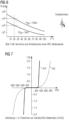
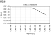
- the resistance of the particle network 5 from Figure 5 is dominated by the Ri-grain and/or Rc-particle contact resistances, which can be bridged by increasing voltage and/or field strength, as well as by increasing frequency.
- a significant reduction in resistance results with increasing voltage and/or frequency.
- the purpose of the particulate network of filler particles is to form a network of many small capacitors and varistors, which are controlled by field strength and frequency
- the bedding polymer matrix of the lacquer layer is only a mechanical fixation, as is also the case with sintered semiconductor ceramics.
- the DC resistance at room temperature and the "alpha" value i.e., the slope in the U-I diagram in a double-logarithmic plot, can be adjusted so that no or only minimal power losses and/or leakage currents occur via the voltage compensation device 3.
- the resistance of device 3 under normal conditions is 3 to 4 decades higher than that of the conductor in the winding, for example, the copper conductor at approximately 1 ohm.
- the invention provides a device 3 for voltage compensation that can be manufactured at very low cost, for example by spraying a plastic substrate.
- This device 3 can be used independently of variances be integrated as a circuit board in the terminal board or terminal box of an electric motor.
- the invention provides for the first time a simple device for voltage compensation that can be variably adapted to the respective electric motor, whereby a partially conductive bridge is created by embedding partially conductive filler particles, present in one or more filler fractions, in a matrix and the polymeric and/or ceramic matrix for embedding with or without a substrate can be freely selected and thus optimally adapted to the respective requirement profile.
Landscapes
- Engineering & Computer Science (AREA)
- Chemical & Material Sciences (AREA)
- Organic Chemistry (AREA)
- Life Sciences & Earth Sciences (AREA)
- Materials Engineering (AREA)
- Wood Science & Technology (AREA)
- Microelectronics & Electronic Packaging (AREA)
- Nanotechnology (AREA)
- Power Engineering (AREA)
- Inorganic Chemistry (AREA)
- Manufacturing & Machinery (AREA)
- Physics & Mathematics (AREA)
- Electromagnetism (AREA)
- Insulation, Fastening Of Motor, Generator Windings (AREA)
Description
- Die Erfindung betrifft eine Vorrichtung zum Spannungsausgleich bei Rechteckspannungen, insbesondere in einer, einer wilden Wicklung von Leitungen in einer Nut eines Elektromotors vorgeschalteten, Klemmbrettschaltung. In Dokument
CN103036485A wird eine Vorrichtung zur Ableitung eines Überstroms in einem Windgenerator beschrieben. Des Weiteren bezieht sich das Dokument auf eine Vorrichtung zur Ableitung eines Überstroms in einem Windgenerator, wenn absehbar ist, dass die Batterie voll sein wird, dann wird eine Überbrückungslösung bereitgestellt. - Niederspannungsmotoren, also Motoren mit einer Spannung bis 1000V "direct-on-line" DOL und/der 690V "variable speed drive" VSD, sind mit einem so genannten "Teilentladungs-freien" Isolationssystem ausgestattet, das der Motoren-Norm IEC 60034-18-41 entspricht. Insbesondere ist das eine Isolation, die einen Drahtlack auf dem Leiter umfasst, beispielsweise in einer Schichtdicke von ca. 200µm und - wiederum beispielsweise - in einem Multilagenaufbau, z. B. mit Polyimiden wie dem Polyamidimid PAI.
- Der so beschichtete Leiter kommt als Kabel, insbesondere in Form einer so genannten "wilden Wicklung" also einer ungeordneten Wicklung, bei der der Draht der 90zigsten Wicklung angrenzend an den Draht der ersten Wicklung zu liegen kommen kann, in eine Nut eines Elektromotors. In der Nut befindet sich in der Regel ein so genannter Nutkasten als Hauptisolation, der standardmäßig eine Art U-förmig gefalztes Papier ist. In der Regel hat das Papier einen Träger, der beidseitig isolierend beschichtet ist, insbesondere mit einem Verbundwerkstoff, Verstärkungsfasern enthaltend, isolierend beschichtet ist. Beispielsweise handelt es sich um das handelsübliche Material NOMEX, das auch beispielsweise über eine Klebeschicht mit dem Träger der Papiernut verbunden sein kann. Der Träger ist beispielsweise eine Kunststofffolie, beispielsweise eine PET Folie. Die Dicke der Folie liegt z.B. im Bereich von 200µm.
- Im Fertigungsverlauf der Herstellung der Elektromotoren werden zuerst die Nutkästen in die Nuten des Metallpakets "eingeschossen". Danach wird die vorgewickelte Leiterdrahtwicklung mechanisch eingezogen.
- Im Bereich der Wickelköpfe werden die Wicklungen der jeweiligen Phasen durch Einlege-Papiere voneinander getrennt, diese Papiere haben in der Regel den gleichen Materialaufbau wie die Nutkästen, die oben beschrieben sind.
- Nach dem Formen der Wickelköpfe und deren Bandagierung werden diese zur Fertigstellung der Isolation in eine Harzmatrix eingebettet. Dabei kommt beispielsweise eine Imprägnierung mit Imprägniermittel, die im Wesentlichen ein flüssiges Harz wie ein Epoxidharz, Polyetherimid -PEI- Harz oder ähnliches umfassen, PEI durch Kalttauchen, Heißtauchen und/oder Träufeln des flüssigen Harzes und nachfolgende Aushärtung zur Anwendung. Durch die Imprägnierung werden die Drahtzwischenräume, die Räume vor und hinter den Nutkästen, sowie die geometrischen Zwickel in den Wickelköpfen zumindest teilweise mit Imprägnierharz gefüllt. Das Imprägnierharz dient zur mechanischen Fixierung und Entwärmung der Leiterwicklung, dient aber als Dielektrikum auch der Isolierung.
- Der Leiter ist dabei durch Drahtlack, Imprägnierung, Nutkasten und weitere Imprägnierung isoliert. Elektrisch kann man sich dabei das Isoliersystem als Kondensator mit verschiedenen dielektrischen Werkstoffen vereinfacht vorstellen, wobei die elektrischen Feldlinien immer in Bereiche mit niedrigem Epsilon verdrängt werden, was im Zweifel immer eine Luft gefüllte Pore und/oder ein unvollständig ausgehärteter Harzbereich des Imprägniermittels ist.
- Ein derartiges Isoliersystem erfüllt die Anforderungen hinsichtlich der Betriebsspannung der Motoren sehr gut, insbesondere hinsichtlich Durchschlagsfestigkeit, Isolationswiderstand, Verlustfaktor. Darüber hinaus ist das System einfach und kostengünstig massenfertigungstauglich herstellbar.
- Die technische Entwicklung hat gezeigt, dass diese Elektromotoren jedoch vermehrt mit Umrichter betrieben und geschaltet, wobei es zu scharfen Schaltvorgängen kommt, die Rechteckspannungen mit wesentlich höheren Spannungsspitzen bei Anstiegsflanken von bis zu 150ns erzeugen. So kommt es isolationsseitig zu deutlichen Spannungs-Überschwingern bei den Schaltvorgängen.
- Ein "Umrichter" ist insbesondere ein Wechselstrom-Umrichter dessen Umrichtung einer Sinusschwingung über eine Frequenzsteuerung in eine Rechteckspannung der direkten Versorgung und Steuerung der Drehzahl einer elektrischen Maschine wie eines Drehstrommotors im Rahmen der elektrischen Antriebstechnik dient.
- Eine Rechteckschwingung bezeichnet ein periodisches Signal, das zwischen zwei Werten hin und her schaltet und in einem Diagramm über der Zeit einen rechteckigen Verlauf aufweist. Der ideal rechteckige Verlauf existiert nur theoretisch. In der Realität können Flanken nicht senkrecht ansteigen und somit einen unendlich steilen Sprung ausführen; den stattdessen realen Sprung beschreiben die Anstiegs- und Abfallzeiten. Unter anderem wegen des kapazitiven und induktiven Verhaltens der Übertragungsleitungen weist ein Rechtecksignal in der Regel ein Unter- und Überschwingen auf. Während das Unterschwingen für die Isolation unerheblich ist, können durch das Überschwingen Spannungsspitzen entstehen, die zu Teilentladungen, die ihrerseits zur Zersetzung der Isolation führen, entstehen.
- Grund dafür ist, dass elektrotechnisch bei Überschwingern eine scharfe Flanke mittels Überlagerungen von sehr hohen Frequenzen im Bereich von beispielsweise 1kHz bis 1MHz, erzeugt werden. In
Figur 1 ist eine Rechteckspannung eines Umrichters mit Überschwinger im Flankenbereich gezeigt. - Dabei zeigt die durchgehende Linie 1 den Spannungsverlauf mit Zielspannung und Überschwinger der Rechteckspannung, wobei tr gleichbleibend ist, die Spannung Upk jedoch deutlich über der Teilentladungs-Einsetzspannung liegt, aber trotzdem keine Teilentladung zu erkennen ist.
- Die Rechteckspannung verläuft beispielsweise so, dass 1000 Volt Spannung mit 0 Volt abwechseln, wobei durch Fourier Transformation die Sinusschwingungen überlagert werden, so dass die Rechteckschwingungen entstehen. Die gestrichelte Linie 2 zeigt die Spannungsmaxima der Sinusschwingungen.
-
Figur 2 zeigt den Verlauf der überschwingenden Spannung im Flankenbereich des Umrichters im Detail. - Die beschriebenen und dargestellten Überspannungen übertreffen häufig die Teilentladungseinsetzspannung im Isolationssystem, z.B. Draht-Draht, welche durch Poren, Hohlräume und Materialwechsel und damit einhergehendes unterschiedliches Epsilon an Schwachpunkten existiert und es kommt somit über das Paschen-Minimum zum Einsetzen von Teilentladungen. Diese Teilentladungen zünden dann im Umrichterbetrieb fortlaufend und werden durch die fortschreitende Erosion des einbettenden Kunststoffes weiter verstärkt, wodurch es relativ zeitnah zum Ausfall des Isolationssystems und somit zum Motordefekt kommt.
-
Figur 3 zeigt die Frequenzüberlagerung einer Rechteckspannung, wie sie für das oben beschriebene Szenario typisch ist. - Das resultierende Teilentladungsproblem zeigt sich - beispielsweise - im Wickelkopf zwischen zwei kritischen und - wegen der wilden Wicklung - sich berührenden Drähten. Ist deren Teilentladungs-Einsetzspannung, die sich im Wesentlichen aus der Drahtisolierung der beiden Drähte, dem Imprägnierharz, dessen Aushärtung und gegebenenfalls mit Luft gefüllten Poren ergibt, überschritten, dann kommt es zu Teilentladungen. Diese Entladungen bewirken - im schlechtesten Fall bei jedem Umrichter-Impuls - eine Oxidation, also Zersetzung des Imprägnierharzes und gegebenenfalls auch des Drahtlackes.
- Dadurch kann es zur vollständigen Entladung über einen Durchschlag kommen. Dann gibt es einen Kurzschluss zwischen den betroffenen Windungen der wilden Wicklung. Das hat zur Folge, dass an dieser Stelle aufgrund des Kurzschlussstromes die Temperatur deutlich ansteigt bis die betroffenen Drähte "durchbrennen". Dadurch wird der Motorstrom unsymmetrisch und die Wicklung brennt als Folge komplett durch oder aber der Umrichter erkennt die Asymmetrie und schaltet ab. In beiden Fällen ist der Motor defekt und irreparabel.
- Eine sehr hochwertige Imprägnierung, die eine nahezu 100% Füllung der Draht/Nutkasten-Zwischenräume bewirkt, würde das Problem zwar lösen, jedoch ist dies entweder mit einem wesentlich teurerem Imprägniermittel und/oder aufwändigerem und damit teurerem Imprägnier-Prozess verbunden.
- Aufgabe der vorliegenden Erfindung ist daher die Schaffung eines preiswerten, effektiven Schutzes vor Schäden des Motors und/oder der Isolation durch Teilentladungen wegen Überschwinger im Betrieb einer elektrischen Maschine mittels Umrichter.
- Diese Aufgabe wird durch den Gegenstand der vorliegenden Erfindung, wie er in der Beschreibung, den Figuren und den Ansprüchen offenbart ist, gelöst.
- Dementsprechend ist Gegenstand der Erfindung eine Vorrichtung zum Spannungsausgleich bei Rechteckspannungen von Elektromotoren mit Klemmbrettschaltung nach Anspruch 1, wobei in der Klemmbrettschaltung die Phasen U, V und W, jeweils in Form von ein- und ausgehenden, verkabelten Leitungen, die sich auf zumindest 6 Kabel addieren, vorliegen, und zumindest eine Brücke zwischen zumindest zwei Kabeln vorgesehen ist, die zwei oder mehr der zumindest 6 Kabel-ein- und -ausgänge verbindet, wobei die Brücke teilleitfähig ist, so dass ihr elektrischer Widerstand ab einem Schwellwert deutlich absinkt, wobei die Teilleitfähigkeit auf Füllstoffpartikel in einer bettenden Matrix basiert, die das Absinken des Widerstandes in der Brücke ab dem Schwellwert maßgeblich beeinflussen.
- Es ist die allgemeine Erkenntnis der Erfindung, dass durch Verbrückung zumindest zweier Phasen einer Klemmbrettschaltung eines Elektromotors, dieser bei Betreiben mittels eines Umrichters vor dem Durchschlagen von Teilentladungen, die bei Rechteckspannungen unvermeidlich sind, geschützt werden kann, dadurch, dass entstehende Teilentladungen durch die Brücke auf Erde und/oder Masse abgeleitet werden und damit den Elektromotor selbst nicht erreichen und nicht belasten. Die Lebensdauer der mit Umrichter betriebenen Elektromotoren kann so um ein Vielfaches gesteigert werden.
- Dies insbesondere deshalb, weil das Verbundmaterial der Brücke bei geringen Spannungen einen hohen Widerstand zeigt, dafür aber bei hohen Spannungen - wie sie bei Teilentladungen auftreten - in Folge des nicht-linearen Verhaltens des Partikel-Widerstandes einen geringen Widerstand zeigt und ausreichend leitfähig wird, damit es eine galvanische Brücke zwischen den zwei oder mehr Kabeln bildet, die die hohe Spannung einer Teilentladung abfängt und ableitet, vor sie auf die Isolation und/oder den Motor auftrifft.
- Unter "Schwellwert" wird hier ein - für das jeweilige Material charakteristischer Wert verstanden. Dieser wird hinsichtlich Frequenz, Spannung und/oder Feldstärke für jedes Material und/oder jede Anwendung naturgemäß eigen zu definieren sein, weil er vom Material, dessen Auftrag, dem Träger und anderen Umgebungsfaktoren abhängt.
- Die Brücke umfasst beispielsweise einen Träger, in der Regel ein isolierendes Substrat, wie eine Leiterplatte, das beispielsweise aus einem Faserverstärkten Kunststoff, insbesondere aus Epoxidharz und/oder Polysiloxan, aus thermoplastischem Kunststoff, wie Polyetheretherketon - PEEK -, Polyamid - PA -, Polyethylen - PE -, Polyethylenterephthalat - PET -, Polybutylenterephthalat - PBT -aber auch aus Holz, Pressspan, Kunststoff, aus Keramik und/oder Leder ist.
- Als Verstärkungsfasern werden dabei z. B. Glasfasern, Kohlefasern, Keramikfasern und/oder Aramidfasern eingesetzt.
- Dieses Substrat selbst kann Teil der bettenden Matrix sein und/oder diese vollständig bilden.
- Grundsätzlich kann die Brücke durch eine Oberflächenbeschichtung eines elektrisch isolierenden Substrates ohne eigene Oberflächenleitfähigkeit mit einem teilleitfähigen Lack, der Füllstoffpartikel enthält, die dem Lack und der damit beschichteten Oberfläche die gewünschte, spannungsabhängige elektrische Leitfähigkeit verleihen.
- Alternativ dazu kann der Füllstoff in einen Kunststoff, der ohne Substrat angewendet kann, eingearbeitet sein, sowie der Füllstoff auch in eine keramische Matrix eingearbeitet sein kann. Eine bevorzugte Form der Applikation des teilleitfähigen Verbundmaterials ist die einfache Beschichtung durch - wiederum beispielsweise Sprühen - eines Substrates mit einem teilleitfähigen Lack.
- Die bettende Matrix des Lackes härtet bevorzugt polymer aus. Zur Bildung des Verbundmaterials, das die Brücke bildet, beispielsweise eines teilleitfähigen Lackes ist die bettende Matrix bevorzugt organisch basiert und nicht keramisch, beispielsweise ein als Duromer aushärtendes Harz oder eine duromer aushärtende Harzmischung. Dabei kommen vernetzende Verbindungen, die Polymere wie Epoxy, Polyetherimid - PEI - Polysiloxan, Polysilazan, jeweils wahlweise mit oder ohne Lösungsmittel, zum Einsatz.
- Anstelle einer bettenden Polymermatrix kann auch eine keramische Sinterschicht zum Einsatz kommen, die zur mechanischen Fixierung der teilleitfähigen Füllstoffpartikel zur Bildung des Verbundmaterials, das die Brücke bildet, nutzbar ist.
- Die Applikation des Lackes auf dem Substrat erfolgt wahlweise nach üblichen Methoden wie beispielsweise Schichtapplikation durch Sprühen, Rakeln, Spincoating, Dipcoating und/oder Pinseln.
- Die Schichtdicken des Lackes liegen zwischen 20 µm bis 1 mm, vorzugsweise zwischen 50 µm und 200 µm, jeweils auch bedingt durch die angewendete Applikation. Die untere Grenze der Dicke des Lackes ist die Partikelgröße der größten Füllstoff-partikelfraktion. Die obere Grenze wird durch die mechanische Stabilität des Lackes, beeinflusst durch Verdampfung des Lösungsmittels, soweit vorhanden, durch Rissbildung im Lack und ähnliche Parameter beeinflusst.
- Im Allgemeinen ist die Lackbeschichtung auf dem Substrat in einer Dicke von 10µm bis mehrere mm, im einstelligen Bereich, zu erwarten. Beispielsweise kann der Lack in der Dicke von 10µm bis 3mm, insbesondere von 15µm bis 2mm und besonders bevorzugt im Bereich von 20µm bis 1mm vorliegen.
- Der Füllstoff kann unimodal, also in einer Füllstofffraktion vorliegen, bevorzugt umfasst er jedoch mehrere Füllstofffraktionen und liegt daher bi- oder multimodal vor.
- Die einzelnen Füllstofffraktionen können sich im Material, der Größe, der Form, des Aufbaus und der Oberflächenbeschaffenheit unterscheiden. Alle Füllstofffraktionen zusammen bilden den Füllstoffgehalt, der bevorzugt oberhalb der Perkolationsschwelle liegt, jedoch - je nach Teilleitfähigen Eigenschaften der Füllstoffpartikel - auch darunter liegen kann.
- Die Füllstoffpartikel können massiv und/oder hohl, beschichtet, teilbeschichtet und/oder unbeschichtet vorliegen.
- Bevorzugt liegen die Füllstoffpartikel in einer polymeren Matrix eingebettet vor.
- Bevorzugt ist dabei, dass die polymere Matrix mit den Füllstoffpartikel und gegebenenfalls Lösungsmittel so aufgearbeitet ist, dass sie versprühbar ist.
- Der Füllstoffgehalt beträgt in der Regel nicht mehr als 30Vol%, wobei bei besonders günstigen Füllstoffpartikel-Eigenschaften hinsichtlich ihrer Varistor-Eigenschaften, auch ganz geringe Füllstoffgehalte wie unter 1Vol%, in so geringen Konzentrationen wie 0,5Vol%, ausreichende Teilleitfähigkeit des Lackes durch die Füllstoffpartikel erzeugt werden kann.
- Bei den am meisten gebräuchlichen keramischen Füllstoffen, wie beispielsweise bei Zinnoxid, Eisenoxid, Zinkoxid, Chromoxid, Manganoxid, Molybdänoxid, Bismutoxid und/oder Siliziumcarbid liegt der Füllstoff in der Regel im Bereich von 20Vol% bis 30Vol% im Lack vor.
- Bei Trägerpartikel, wie hohle Glaspartikel mit dotierter Beschichtung, können die gewünschten Varistor-Eigenschaften im Lack auch bei wesentlich geringeren Füllstoffmengen - beispielsweise im Bereich von 0,5Vol% bis 5Vol%, insbesondere im Bereich 1Vol% bis 10Vol% - erzeugt werden.
- Die Partikelgrößen für Körner als Partikel, globular, splittrig, ohne spezielle Form, so dass vom Hersteller eine durchschnittliche Korngröße angegeben wird, beispielsweise über REM-Aufnahmen gemessen, der Füllstofffraktionen liegen im Bereich von 500nm bis 50µm, insbesondere im Bereich von 2µm bis 20 µm. Eine Mischung von verschiedenen Partikelgrößenfraktionen führt zu verbesserten Verarbeitungseigenschaften des Lackes.
- Beispiele dazu:
- 3 Größenfraktionen von
- 0,5 µm, 10µm und 50 µm
- 700nm, 1µm und 14µm
- 0,6µm, 15µm und 47µm
- 800nm, 12µm und 45µm
- 0,8µm, 11µm und 43µm
- 4 Größenfraktionen
- 800nm, 8µm, 17µm und 45µm oder
- 700nm, 11µm, 23 µm und 40µm
- Diese und ähnliche, insbesondere in den oben genannten Größenbereichen liegende, Kombinationen führen zu niedrigerer Verarbeitungsviskosität, also besserer Verarbeitbarkeit und niedrigerer Perkolationsschwelle.
- Zum Material: Die Füllstoffpartikel sind bevorzugt aus einem keramischen Material, insbesondere einem Metalloxid, einem Metallcarbid, wie Siliziumcarbid und/oder einem Metallnitrid.
- Beispielsweise liegt Siliziumcarbid und/oder Zinnoxid in verschiedenen Partikelgrößenfraktionen vor.
- Die Füllstofffraktionen können sich darin unterscheiden, dass sie einerseits beschichtete Füllstoffpartikel und andererseits nicht beschichtete Füllstoffpartikel umfassen. Dabei sind nicht beschichtete Füllstoffpartikel bevorzugt massiv aufgebaut, wohingegen beschichtete Füllstoffpartikel auch hohl sein können, sie dienen dann als Formfaktor.
- Die massiven, unter Umständen auch beschichteten Füllstoffpartikel sind beispielsweise aus einem Metalloxid, Metallcarbid und/oder einem Metallnitrid, können aber auch eine Mischung aus diesen Metallverbindungen bilden und/oder eine Metallmischverbindung umfassen.
- Beispiel für einen massiven Füllstoff mit Beschichtung ist ein Füllstoff in Plättchen-Form mit hohem Aspektverhältnis, insbesondere den Dimensionen 7µm Durchmesser und 300nm Dicke, der eine 50nm dicke Beschichtung mit Zinnoxid - SnO2 - hat, die ihrerseits Antimon-dotiert vorliegt.
- Eine Metallmischverbindung ist ein gemischtes Metalloxid, wie beispielsweise ein Stannat und/oder ein Titanat. Es können aber auch Mischungen mit Zinnoxid, Zinkoxid, Eisenoxid, Titanoxid, Manganoxid und Bismutoxid eingesetzt werden. Grundsätzlich sind bei den Dotierungen der Beschichtungen der Füllstoffpartikel insbesondere die n-leitenden Dotierungen bekannt, bei den Metallmischverbindungen können jedoch auch p-Dotierungen in der Beschichtung sinnvoll eingesetzt werden.
- Die Füllstoffpartikel sind z.B. metalloxidische Übergangsmetallverbindungen mit Zinn, Chrom, Molybdän, Eisen und Zink. Bevorzugt bilden die Füllstoffpartikel ein Oxid oder ein Carbid mit zumindest einem der folgenden Elementen, auch mehrere Elemente bilden unter Umständen zusammen ein Oxid: Zinn, Zink, Eisen, Molybdän, Bismut, Blei, Chrom, Mangan, Nickel, Cobalt, Titan, Vanadium, Indium, Zirkonium, Wolfram, Silizium, Antimon, Tellur, Germanium.
- Füllstofffraktionen mit Füllstoffpartikeln, die einen Hohlraum - einen Formfaktor bildend - einschließen sind beispielsweise aus Glimmer, Glas, Kohlenstoff, wie beispielsweise Kohlenstoffnanoröhrchen - CNTs - oder sonstiger Keramik. Diese haben dann eine teilleitfähige Beschichtung, beispielsweise aus einem Metalloxid Zinnoxid, Bismutoxid, Titanoxid und/oder mit Siliziumcarbid.
- Eine teilleitfähige Beschichtung kann bei den massiven und bei den hohlen Füllstoffpartikeln gleichermaßen vorliegen.
- Nach einer vorteilhaften Ausführungsform ist die teilleitfähige Beschichtung der Füllstoffpartikel dotiert, insbesondere n-leitend dotiert, z.B. mit Elementen wie Halogen, Pseudohalogen, insbesondere Jod, Antimon, Fluor.
- Die Dotierungsmenge liegt beispielsweise im Bereich bis zu 5mol%, insbesondere bei 1mol% bis 3mol%.
- Die Beschichtung auf den Füllstoffpartikeln liegt beispielsweise mit einer Schichtdicke im Bereich zwischen 10nm bis 100nm, insbesondere zwischen 15nm und 80nm, insbesondere zwischen 20nm und 70nm, vor.
-
Figur 4 zeigt beispielhaft und schematisch die Wirkung der durch die Erfindung vorgeschlagenen Vorrichtung zum Spannungsausgleich bei Rechteckspannungen von Elektromotoren mit Klemmbrettschaltung. Die elektrisch teilleitfähige Vorrichtung wird in die Klemmbrettschaltung eingefügt, so dass über die kontaktierende, eine - bei hohen Spannungen, wie sie bei Teilentladungen entstehen, gebildete - elektrische Brücke bildende Vorrichtung hinweg jeweils Anfang und Ende der Phasen U, V und W sowie jede Phase mit Erde kurzgeschlossen ist. - Man erkennt in
Figur 4 eine idealisierte Wicklung 4, die die Phase U bildet. Die beiden Enden Uin und Uout werden beispielsweise durch Kabel-Anschlüsse im Klemmkasten - nicht gezeigt - realisiert. Schaltungstechnisch zwischen Uin und Uout wird im Klemmkasten dann die Vorrichtung 3 zum Spannungsausgleich angebracht, so dass zwischen Uout, Uin und Erde im Fall einer hohen Spannung eine elektrische Verbindung besteht, die jedoch im Falle der normalen Spannung des Motors keine Leitfähigkeit zeigt. -
Figur 5 zeigt den Aufbau des Lackes der Vorrichtung 3 aus Figur 4, der Vorrichtung zum Spannungsausgleich gemäß einer Ausführungsform der Erfindung, insbesondere den Verlauf der elektrischen Leitfähigkeit innerhalb des Lackes, im Detail. - Zu erkennen ist die den Lack bildende bettende Polymermatrix 7, in der eine Füllstofffraktion 5, viele meist aneinandergrenzende einzelne Füllstoffpartikel 5 umfassend, eingebettet ist. Wie bereits erwähnt liegt der Füllstoff 5 vorzugsweise auch in Form mehrerer Füllstofffraktionen, die sich in Form und Größe der Füllstoffpartikel hier in der Darstellung unterscheiden würden, vor. Der Einfachheit halber wird hier aber nur die eine Füllstoff-Partikelfraktion 5 aus gleichen Füllstoffpartikeln 5 gezeigt.
- Zu erkennen ist auch der Leitfähigkeitspfad 6, der sich bei hohen Spannungen ausbildet, weil dann der innere Widerstand Ri der einzelnen Füllstoffpartikel 5 und der Widerstand Rc zwischen einzelnen, gegebenenfalls - aber nicht unbedingt zwingend - aneinandergrenzenden, Füllstoffpartikeln 5 drastisch sinkt. Die Füllstoffpartikel 5 werden so gewählt, dass sie im Lack 7 Varistor-Eigenschaften erzeugen, so dass der Lack 7 bei den normalen Betriebsspannungen des Elektromotors elektrisch nichtleitend, aber oberhalb eines Schwellwertes, wie beispielsweise einer Schwellspannung, die je nach Lack 7 unterschiedlich hoch ist, eine gute elektrische Leitfähigkeit zeigt. Dann bildet sich der Leitfähigkeitspfad 6 innerhalb des Lackes 7 der Vorrichtung zum Spannungsabbau 3, wie in Figur 5 gezeigt, aus.
- Über den gebildeten Leitfähigkeitspfad 6 wird die hohe Spannung abgeführt, ohne dass sie durch die idealisierte Wicklung, wie in
Figur 4 gezeigt, respektive den Elektromotor fließt. - Damit wird der Elektromotor vor Schäden durch Teilentladungen, wie sie bei Umrichter-betriebenen Elektromotoren sonst entstehen, wirksam und effektiv geschützt.
- Die
Figuren 6, 7 und8 zeigen im Detail, wie der Abfall des Widerstandes durch kurzzeitig auftretende hohe Spannungen innerhalb des Lackes, der Teil der Vorrichtung 3 zum Spannungsabbau ist, erklärbar ist. Der Widerstand des Partikelnetzwerkes 5 ausFigur 5 ist dominiert durch die Ri-Korn- und/oder Rc-Partikel-übergangswiderstände, welche durch erhöhte Spannung und/oder Feldstärke, sowie durch erhöhte Frequenz überbrückt werden können. Somit ergibt sich eine deutliche Verringerung des Widerstands mit zunehmender Spannung und/oder Frequenz. - Der Sinn des partikulären Netzwerks der Füllstoffpartikel ist die Bildung eines Netzwerkes aus vielen kleinen Kondensatoren und Varistoren, welche durch Feldstärke und Frequenz gesteuert werden. Die bettende Polymermatrix der Lackschicht ist hier nur eine mechanische Fixierung, wie sie auch gesinterte Halbleiterkeramiken zeigen.
- Dadurch, dass im Bereich des Umrichter-Schaltvorgangs, wie in den
Figuren 1 bis 3 gezeigt, Überschwinger mit sehr hohen Frequenzen, also beispielsweise mit Frequenzen höher 1kHz bei gleichzeitig einem Vielfachen der eigentlichen Spannungen ankommen, wird der Lack durch den Varistor-Effekt, wie inFigur 7 gezeigt und den Effekt des frequenzabhängigen Widerstandes, wie inFigur 8 gezeigt, deutlich leitfähiger als für die niederfrequente Anteile mit geringerer Spannung. Somit wird also der inAbbildung 1 bis 3 gezeigte Überschwinger mit deutlich erhöhter Frequenz und höherer Spannung über die in diesem Bereich "niederohmige" Vorrichtung zum Spannungsausgleich 3 teilweise oder ganz abgeleitet und somit um dieses Maß abgeschwächt, so dass die kritische Teilentladungs- Einsetzspannung nicht mehr erreicht wird und somit ein Schutz gegenüber Umrichter-bedingte Teilentladungen erzeugt wird. - Durch die Wahl der Füllstofffraktionen hinsichtlich Material, Beschichtung, Dotierung, Füllstoffpartikel-Größenverteilung und - Formen, sowie der Füllstoffpartikel-Massenkonzentration im Lack kann der Gleichspannungswiderstand bei Raumtemperatur sowie der "alpha"-Wert, also die Steigung im U-I-Diagramm in doppel-logarithmischer Auftragung so eingestellt werden, dass keine oder nur geringe Leistungsverluste und/oder Verlustströme über die Vorrichtung zum Spannungsausgleich 3 entstehen. Beispielsweise liegt der Widerstand der Vorrichtung 3 bei normalen Bedingungen um 3 bis 4 Dekaden höher als der des Leiters in der Wicklung, beispielsweise der des Kupferleiters mit ca. 1 Ohm.
- Durch die Erfindung wird eine Vorrichtung 3 zum Spannungsausgleich zur Verfügung gestellt, die mit sehr geringen Kosten herstellbar ist, also beispielsweise durch Besprühen eines Kunststoffsubstrates. Diese Vorrichtung 3 kann varianzunabhängig als Leiterplatte im Klemmbrett oder Klemmkasten eines Elektromotors integriert werden.
- Durch Wahl der Füllstoffpartikel-Fraktionen ist eine stufenlose Anpassung an die jeweiligen Betriebsspannungen und Betriebsfrequenzen möglich.
- Dies wird durch einen einfachen Lack erreicht, in dem sich ein partikulär teilleitfähiges Netzwerk befindet und der sich - beispielsweise - einfach aufsprühen lässt.
- Die Erfindung stellt erstmals eine einfache und variabel an den jeweiligen Elektromotor anpassbare Vorrichtung zum Spannungsausgleich zur Verfügung, wobei durch die Einbettung von teilleitfähigen Füllstoffpartikeln, in einer oder mehreren Füllstofffraktionen vorliegend, in eine Matrix eine teilleitfähige Brücke erzeugt wird und die polymere und/oder keramische Matrix zur Einbettung mit oder ohne Substrat frei wählbar und damit dem jeweiligen Anforderungsprofil optimal anpassbar ist.
Claims (15)
- Vorrichtung zum Spannungsausgleich bei Rechteckspannungen von Elektromotoren mit Klemmbrettschaltung, wobei in der Klemmbrettschaltung die Phasen U, V und W, jeweils in Form von ein- und ausgehenden, verkabelten Leitungen, die sich auf zumindest 6 Kabel addieren, vorliegen, und zumindest eine teilleitfähige Oberflächenbeschichtung, deren Teilleitfähigkeit auf Füllstoffpartikel in einer bettenden Matrix basiert, die das Absinken des Widerstandes in der Brücke ab dem Schwellwert maßgeblich beeinflussen, als Brücke zwischen zumindest zwei Kabeln vorgesehen ist, die zwei oder mehr der zumindest 6 Kabel-ein- und -ausgänge verbindet, und die teilleitfähige Beschichtung sich dadurch auszeichnet, dass sie einen Varistor darstellt, also ihr elektrischer Widerstand ab einem Schwellwert deutlich absinkt.
- Vorrichtung nach Anspruch 1, wobei die Füllstoffpartikel in einer polymeren und/oder keramischen Matrix eingebettet sind.
- Vorrichtung nach einem der Ansprüche 1 oder 2, wobei die Füllstoffpartikel zumindest zum Teil eine teilleitfähige Beschichtung haben.
- Vorrichtung nach Anspruch 3, wobei die teilleitfähige Beschichtung der Füllstoffpartikel dotiert vorliegt.
- Vorrichtung nach Anspruch 3 oder 4, wobei die Dicke der teilleitfähigen Beschichtung der Füllstoffpartikel im Bereich von 10nm bis 100nm liegt.
- Vorrichtung nach einem der vorhergehenden Ansprüche, wobei zumindest eine Fraktion der Füllstoffpartikel hohle Füllstoffpartikel umfasst, die eine teilleitfähige Beschichtung, insbesondere nach einem der Ansprüche 4 oder 5, haben.
- Vorrichtung nach einem der vorhergehenden Ansprüche, wobei ein Substrat aus Holz, Pressspan, Kunststoff, insbesondere aus Epoxidharz und/oder Polysiloxan, aus thermoplastischem Kunststoff, wie PEEK, PA, PE, PET, PBT, aus Faserverstärktem Kunststoff, aus Keramik und/oder Leder, vorliegt, das die bettende Matrix samt Füllstoffpartikel trägt.
- Vorrichtung nach einem der vorhergehenden Ansprüche, wobei die bettende Matrix mit den Füllstoffpartikeln einen Lack bildet.
- Vorrichtung nach Anspruch 7 oder 8, wobei der Lack ein Harz oder eine Harzmischung mit einer der Verbindungen Epoxidharz, Polyetherimid, Polysiloxan, Polysilazan, allein oder in beliebiger Kombination umfasst.
- Vorrichtung nach einem der vorhergehenden Ansprüche 7 bis 9, wobei der Lack in einer Schichtdicke im Bereich zwischen 10µm und 3mm auf dem Substrat aufgebracht ist.
- Vorrichtung nach einem der vorhergehenden Ansprüche, wobei die Füllstoffpartikel aus einem Metalloxid, Metallcarbid und/oder einem Metallnitrid sind, eine Mischung aus diesen Metallverbindungen bilden und/oder eine Metallmischverbindung umfassen.
- Vorrichtung nach Anspruch 11, wobei die Füllstoffpartikel ein Oxid und/oder ein Carbid mit zumindest einem der folgenden Elemente, auch mehrere Elemente zusammen, bilden: Zinn, Zink, Eisen, Molybdän, Bismut, Blei, Chrom, Mangan, Nickel, Cobalt, Titan, Vanadium, Indium, Zirkonium, Wolfram, Silizium, Antimon, Tellur, Germanium.
- Vorrichtung nach einem der vorhergehenden Ansprüche, wobei die Füllstoffpartikel in der bettenden Matrix in einer Konzentration von 0,5Vol% bis 30Vol% vorliegen.
- Vorrichtung nach einem der vorhergehenden Ansprüche, wobei die Größe der Füllstoffpartikel im Bereich von 500nm bis 50µm liegt.
- Vorrichtung nach einem der vorhergehenden Ansprüche, wobei der Füllstoff in mehreren Füllstofffraktionen vorliegt.
Applications Claiming Priority (2)
| Application Number | Priority Date | Filing Date | Title |
|---|---|---|---|
| EP19207121.5A EP3819920A1 (de) | 2019-11-05 | 2019-11-05 | Vorrichtung zum spannungsausgleich bei rechteckspannungen für ein elektromotor |
| PCT/EP2020/078457 WO2021089271A1 (de) | 2019-11-05 | 2020-10-09 | Vorrichtung zum spannungsausgleich bei rechteckspannungen für ein elektromotor |
Publications (2)
| Publication Number | Publication Date |
|---|---|
| EP4035189A1 EP4035189A1 (de) | 2022-08-03 |
| EP4035189B1 true EP4035189B1 (de) | 2025-06-25 |
Family
ID=68470240
Family Applications (2)
| Application Number | Title | Priority Date | Filing Date |
|---|---|---|---|
| EP19207121.5A Pending EP3819920A1 (de) | 2019-11-05 | 2019-11-05 | Vorrichtung zum spannungsausgleich bei rechteckspannungen für ein elektromotor |
| EP20797391.8A Active EP4035189B1 (de) | 2019-11-05 | 2020-10-09 | Vorrichtung zum spannungsausgleich bei rechteckspannungen für ein elektromotor |
Family Applications Before (1)
| Application Number | Title | Priority Date | Filing Date |
|---|---|---|---|
| EP19207121.5A Pending EP3819920A1 (de) | 2019-11-05 | 2019-11-05 | Vorrichtung zum spannungsausgleich bei rechteckspannungen für ein elektromotor |
Country Status (4)
| Country | Link |
|---|---|
| US (1) | US12348100B2 (de) |
| EP (2) | EP3819920A1 (de) |
| CN (1) | CN114830269A (de) |
| WO (1) | WO2021089271A1 (de) |
Families Citing this family (2)
| Publication number | Priority date | Publication date | Assignee | Title |
|---|---|---|---|---|
| EP3819920A1 (de) | 2019-11-05 | 2021-05-12 | Siemens Aktiengesellschaft | Vorrichtung zum spannungsausgleich bei rechteckspannungen für ein elektromotor |
| EP4554060A1 (de) * | 2023-11-08 | 2025-05-14 | Innomotics GmbH | Dynamoelektrische maschine mit einem teilentladungssensitiven isolierstoff |
Citations (2)
| Publication number | Priority date | Publication date | Assignee | Title |
|---|---|---|---|---|
| EP0977337B1 (de) * | 1998-07-30 | 2011-03-09 | Diehl AKO Stiftung & Co. KG | Schaltungsanordnung zur Messung und Begrenzung von Strömen in Umrichtern zur Speisung von Motoren |
| CN103036485A (zh) * | 2012-12-03 | 2013-04-10 | 北京科诺伟业科技有限公司 | 永磁直流电机启动冲击电流抑制装置及其抑制方法 |
Family Cites Families (7)
| Publication number | Priority date | Publication date | Assignee | Title |
|---|---|---|---|---|
| GB0622060D0 (en) * | 2006-11-06 | 2006-12-13 | Hexcel Composites Ltd | Improved composite materials |
| US9208931B2 (en) * | 2008-09-30 | 2015-12-08 | Littelfuse, Inc. | Voltage switchable dielectric material containing conductor-on-conductor core shelled particles |
| EP2577716A1 (de) | 2010-05-24 | 2013-04-10 | Shocking Technologies Inc | Schaltkreiselemente mit ferroischen materialien |
| DE102011079813A1 (de) * | 2011-07-26 | 2013-01-31 | Siemens Aktiengesellschaft | Spannungsbegrenzende Zusammensetzung |
| US10254499B1 (en) * | 2016-08-05 | 2019-04-09 | Southern Methodist University | Additive manufacturing of active devices using dielectric, conductive and magnetic materials |
| DE102017109049A1 (de) | 2017-04-27 | 2018-10-31 | Schaeffler Technologies AG & Co. KG | Vorrichtung und Verfahren zur Kompensation von Wellenspannung und Lagerströmen durch kapazitive Gegenkopplung |
| EP3819920A1 (de) | 2019-11-05 | 2021-05-12 | Siemens Aktiengesellschaft | Vorrichtung zum spannungsausgleich bei rechteckspannungen für ein elektromotor |
-
2019
- 2019-11-05 EP EP19207121.5A patent/EP3819920A1/de active Pending
-
2020
- 2020-10-09 CN CN202080087081.7A patent/CN114830269A/zh active Pending
- 2020-10-09 WO PCT/EP2020/078457 patent/WO2021089271A1/de not_active Ceased
- 2020-10-09 EP EP20797391.8A patent/EP4035189B1/de active Active
- 2020-10-09 US US17/774,320 patent/US12348100B2/en active Active
Patent Citations (2)
| Publication number | Priority date | Publication date | Assignee | Title |
|---|---|---|---|---|
| EP0977337B1 (de) * | 1998-07-30 | 2011-03-09 | Diehl AKO Stiftung & Co. KG | Schaltungsanordnung zur Messung und Begrenzung von Strömen in Umrichtern zur Speisung von Motoren |
| CN103036485A (zh) * | 2012-12-03 | 2013-04-10 | 北京科诺伟业科技有限公司 | 永磁直流电机启动冲击电流抑制装置及其抑制方法 |
Also Published As
| Publication number | Publication date |
|---|---|
| CN114830269A (zh) | 2022-07-29 |
| US12348100B2 (en) | 2025-07-01 |
| EP3819920A1 (de) | 2021-05-12 |
| EP4035189A1 (de) | 2022-08-03 |
| WO2021089271A1 (de) | 2021-05-14 |
| US20220393537A1 (en) | 2022-12-08 |
Similar Documents
| Publication | Publication Date | Title |
|---|---|---|
| DE69528833T2 (de) | Verfahren zur herstellung von ein- und mehrschicht-schutzvorrichtungen gegen veränderliche spannung | |
| EP2661760B1 (de) | Schirmring für eine hgü-transformatorspule oder eine hgü-drosselspule | |
| EP3278423B1 (de) | Widerstandsbelag für einen glimmschutz einer elektrischen maschine | |
| EP2740197B1 (de) | Elektrische leitungseinrichtung, endenglimmschutzanordnung und verfahren zum herstellen eines endenglimmschutzes | |
| EP3078033B1 (de) | Leitfähiges glimmschutzpapier, insbesondere für den aussenglimmschutz | |
| WO2017134040A1 (de) | Schirmring für eine transformatorspule | |
| EP3642857A1 (de) | Elektromagnetisch erregbare spule | |
| EP2661761B1 (de) | Leitungsführung für hgü-transformatorspulen oder hgü-drosselspulen | |
| EP3819920A1 (de) | Vorrichtung zum spannungsausgleich bei rechteckspannungen für ein elektromotor | |
| EP4272300A1 (de) | Nutisolationssystem für eine elektrische rotierende maschine, verfahren zur herstellung eines nutisolationssystems | |
| WO2015128367A1 (de) | Glimmschutzsystem, insbesondere aussenglimmschutzsystem für eine elektrische maschine | |
| EP3505943B1 (de) | Nachweisen einer elektrischen überspannung | |
| WO2021160355A1 (de) | Teilentladungsverhindernde wickelkopfimprägnierung | |
| EP3417539B1 (de) | Stromrichter | |
| EP3218908B1 (de) | Glimmschutzmaterial mit einstellbarem widerstand | |
| DE102017212026A1 (de) | Schirmring und/oder Steigungsausgleich für eine Transformatorspule | |
| EP3410451B1 (de) | Schirmring für eine transformatorspule | |
| EP4016576B1 (de) | Elektrische schaltvorrichtung für mittel- und/oder hochspannungsanwendungen | |
| EP3410450A1 (de) | Schirmring und/oder steigungsausgleich für eine transformatorspule | |
| EP2661523B1 (de) | Leitungsdurchführung für die kesselwand einer hgü-komponente | |
| WO2004107371A1 (de) | Elektrische anordnung, elektrische einrichtung, kabel und draht, sowie die verfahren zum herstellen einer elektrischen anordnung | |
| DE102014203743A1 (de) | Glimmschutzsystem, insbesondere Außenglimmschutzsystem für eine elektrische Maschine |
Legal Events
| Date | Code | Title | Description |
|---|---|---|---|
| STAA | Information on the status of an ep patent application or granted ep patent |
Free format text: STATUS: UNKNOWN |
|
| STAA | Information on the status of an ep patent application or granted ep patent |
Free format text: STATUS: THE INTERNATIONAL PUBLICATION HAS BEEN MADE |
|
| PUAI | Public reference made under article 153(3) epc to a published international application that has entered the european phase |
Free format text: ORIGINAL CODE: 0009012 |
|
| STAA | Information on the status of an ep patent application or granted ep patent |
Free format text: STATUS: REQUEST FOR EXAMINATION WAS MADE |
|
| 17P | Request for examination filed |
Effective date: 20220427 |
|
| AK | Designated contracting states |
Kind code of ref document: A1 Designated state(s): AL AT BE BG CH CY CZ DE DK EE ES FI FR GB GR HR HU IE IS IT LI LT LU LV MC MK MT NL NO PL PT RO RS SE SI SK SM TR |
|
| DAV | Request for validation of the european patent (deleted) | ||
| DAX | Request for extension of the european patent (deleted) | ||
| RAP1 | Party data changed (applicant data changed or rights of an application transferred) |
Owner name: INNOMOTICS GMBH |
|
| REG | Reference to a national code |
Ref legal event code: R079 Free format text: PREVIOUS MAIN CLASS: H01C0007100000 Ref country code: DE Ref document number: 502020011310 Country of ref document: DE Ipc: H01C0017065000 |
|
| GRAP | Despatch of communication of intention to grant a patent |
Free format text: ORIGINAL CODE: EPIDOSNIGR1 |
|
| STAA | Information on the status of an ep patent application or granted ep patent |
Free format text: STATUS: GRANT OF PATENT IS INTENDED |
|
| RIC1 | Information provided on ipc code assigned before grant |
Ipc: H02K 11/26 20160101ALI20241218BHEP Ipc: H01C 7/105 20060101ALI20241218BHEP Ipc: H01C 17/065 20060101AFI20241218BHEP |
|
| INTG | Intention to grant announced |
Effective date: 20250103 |
|
| GRAS | Grant fee paid |
Free format text: ORIGINAL CODE: EPIDOSNIGR3 |
|
| GRAA | (expected) grant |
Free format text: ORIGINAL CODE: 0009210 |
|
| STAA | Information on the status of an ep patent application or granted ep patent |
Free format text: STATUS: THE PATENT HAS BEEN GRANTED |
|
| P01 | Opt-out of the competence of the unified patent court (upc) registered |
Free format text: CASE NUMBER: APP_19694/2025 Effective date: 20250424 |
|
| AK | Designated contracting states |
Kind code of ref document: B1 Designated state(s): AL AT BE BG CH CY CZ DE DK EE ES FI FR GB GR HR HU IE IS IT LI LT LU LV MC MK MT NL NO PL PT RO RS SE SI SK SM TR |
|
| REG | Reference to a national code |
Ref country code: GB Ref legal event code: FG4D Free format text: NOT ENGLISH |
|
| REG | Reference to a national code |
Ref country code: CH Ref legal event code: EP |
|
| REG | Reference to a national code |
Ref country code: CH Ref legal event code: EP |
|
| REG | Reference to a national code |
Ref country code: IE Ref legal event code: FG4D Free format text: LANGUAGE OF EP DOCUMENT: GERMAN |
|
| REG | Reference to a national code |
Ref country code: DE Ref legal event code: R096 Ref document number: 502020011310 Country of ref document: DE |
|
| PG25 | Lapsed in a contracting state [announced via postgrant information from national office to epo] |
Ref country code: FI Free format text: LAPSE BECAUSE OF FAILURE TO SUBMIT A TRANSLATION OF THE DESCRIPTION OR TO PAY THE FEE WITHIN THE PRESCRIBED TIME-LIMIT Effective date: 20250625 |
|
| REG | Reference to a national code |
Ref country code: LT Ref legal event code: MG9D |
|
| PG25 | Lapsed in a contracting state [announced via postgrant information from national office to epo] |
Ref country code: NO Free format text: LAPSE BECAUSE OF FAILURE TO SUBMIT A TRANSLATION OF THE DESCRIPTION OR TO PAY THE FEE WITHIN THE PRESCRIBED TIME-LIMIT Effective date: 20250925 Ref country code: GR Free format text: LAPSE BECAUSE OF FAILURE TO SUBMIT A TRANSLATION OF THE DESCRIPTION OR TO PAY THE FEE WITHIN THE PRESCRIBED TIME-LIMIT Effective date: 20250926 |
|
| PG25 | Lapsed in a contracting state [announced via postgrant information from national office to epo] |
Ref country code: BG Free format text: LAPSE BECAUSE OF FAILURE TO SUBMIT A TRANSLATION OF THE DESCRIPTION OR TO PAY THE FEE WITHIN THE PRESCRIBED TIME-LIMIT Effective date: 20250625 |
|
| PG25 | Lapsed in a contracting state [announced via postgrant information from national office to epo] |
Ref country code: HR Free format text: LAPSE BECAUSE OF FAILURE TO SUBMIT A TRANSLATION OF THE DESCRIPTION OR TO PAY THE FEE WITHIN THE PRESCRIBED TIME-LIMIT Effective date: 20250625 |
|
| PG25 | Lapsed in a contracting state [announced via postgrant information from national office to epo] |
Ref country code: RS Free format text: LAPSE BECAUSE OF FAILURE TO SUBMIT A TRANSLATION OF THE DESCRIPTION OR TO PAY THE FEE WITHIN THE PRESCRIBED TIME-LIMIT Effective date: 20250925 |
|
| PG25 | Lapsed in a contracting state [announced via postgrant information from national office to epo] |
Ref country code: LV Free format text: LAPSE BECAUSE OF FAILURE TO SUBMIT A TRANSLATION OF THE DESCRIPTION OR TO PAY THE FEE WITHIN THE PRESCRIBED TIME-LIMIT Effective date: 20250625 |
|
| REG | Reference to a national code |
Ref country code: NL Ref legal event code: MP Effective date: 20250625 |
|
| PG25 | Lapsed in a contracting state [announced via postgrant information from national office to epo] |
Ref country code: NL Free format text: LAPSE BECAUSE OF FAILURE TO SUBMIT A TRANSLATION OF THE DESCRIPTION OR TO PAY THE FEE WITHIN THE PRESCRIBED TIME-LIMIT Effective date: 20250625 |
|
| PG25 | Lapsed in a contracting state [announced via postgrant information from national office to epo] |
Ref country code: PT Free format text: LAPSE BECAUSE OF FAILURE TO SUBMIT A TRANSLATION OF THE DESCRIPTION OR TO PAY THE FEE WITHIN THE PRESCRIBED TIME-LIMIT Effective date: 20251027 |
|
| PG25 | Lapsed in a contracting state [announced via postgrant information from national office to epo] |
Ref country code: IS Free format text: LAPSE BECAUSE OF FAILURE TO SUBMIT A TRANSLATION OF THE DESCRIPTION OR TO PAY THE FEE WITHIN THE PRESCRIBED TIME-LIMIT Effective date: 20251025 |
|
| PGFP | Annual fee paid to national office [announced via postgrant information from national office to epo] |
Ref country code: DE Payment date: 20251029 Year of fee payment: 6 |
|
| PG25 | Lapsed in a contracting state [announced via postgrant information from national office to epo] |
Ref country code: SM Free format text: LAPSE BECAUSE OF FAILURE TO SUBMIT A TRANSLATION OF THE DESCRIPTION OR TO PAY THE FEE WITHIN THE PRESCRIBED TIME-LIMIT Effective date: 20250625 |
|
| PGFP | Annual fee paid to national office [announced via postgrant information from national office to epo] |
Ref country code: IT Payment date: 20251024 Year of fee payment: 6 |
|
| PG25 | Lapsed in a contracting state [announced via postgrant information from national office to epo] |
Ref country code: CZ Free format text: LAPSE BECAUSE OF FAILURE TO SUBMIT A TRANSLATION OF THE DESCRIPTION OR TO PAY THE FEE WITHIN THE PRESCRIBED TIME-LIMIT Effective date: 20250625 |
|
| PG25 | Lapsed in a contracting state [announced via postgrant information from national office to epo] |
Ref country code: PL Free format text: LAPSE BECAUSE OF FAILURE TO SUBMIT A TRANSLATION OF THE DESCRIPTION OR TO PAY THE FEE WITHIN THE PRESCRIBED TIME-LIMIT Effective date: 20250625 |
|
| PG25 | Lapsed in a contracting state [announced via postgrant information from national office to epo] |
Ref country code: EE Free format text: LAPSE BECAUSE OF FAILURE TO SUBMIT A TRANSLATION OF THE DESCRIPTION OR TO PAY THE FEE WITHIN THE PRESCRIBED TIME-LIMIT Effective date: 20250625 |
|
| PG25 | Lapsed in a contracting state [announced via postgrant information from national office to epo] |
Ref country code: SK Free format text: LAPSE BECAUSE OF FAILURE TO SUBMIT A TRANSLATION OF THE DESCRIPTION OR TO PAY THE FEE WITHIN THE PRESCRIBED TIME-LIMIT Effective date: 20250625 |
|
| PG25 | Lapsed in a contracting state [announced via postgrant information from national office to epo] |
Ref country code: ES Free format text: LAPSE BECAUSE OF FAILURE TO SUBMIT A TRANSLATION OF THE DESCRIPTION OR TO PAY THE FEE WITHIN THE PRESCRIBED TIME-LIMIT Effective date: 20250625 |
|
| PG25 | Lapsed in a contracting state [announced via postgrant information from national office to epo] |
Ref country code: RO Free format text: LAPSE BECAUSE OF FAILURE TO SUBMIT A TRANSLATION OF THE DESCRIPTION OR TO PAY THE FEE WITHIN THE PRESCRIBED TIME-LIMIT Effective date: 20250625 |
|
| PG25 | Lapsed in a contracting state [announced via postgrant information from national office to epo] |
Ref country code: DK Free format text: LAPSE BECAUSE OF FAILURE TO SUBMIT A TRANSLATION OF THE DESCRIPTION OR TO PAY THE FEE WITHIN THE PRESCRIBED TIME-LIMIT Effective date: 20250625 |
|
| PLBE | No opposition filed within time limit |
Free format text: ORIGINAL CODE: 0009261 |
|
| STAA | Information on the status of an ep patent application or granted ep patent |
Free format text: STATUS: NO OPPOSITION FILED WITHIN TIME LIMIT |
|
| REG | Reference to a national code |
Ref country code: CH Ref legal event code: L10 Free format text: ST27 STATUS EVENT CODE: U-0-0-L10-L00 (AS PROVIDED BY THE NATIONAL OFFICE) Effective date: 20260507 |