EP4034748B1 - Heben von kondensat aus bohrlöchern - Google Patents
Heben von kondensat aus bohrlöchern Download PDFInfo
- Publication number
- EP4034748B1 EP4034748B1 EP20789332.2A EP20789332A EP4034748B1 EP 4034748 B1 EP4034748 B1 EP 4034748B1 EP 20789332 A EP20789332 A EP 20789332A EP 4034748 B1 EP4034748 B1 EP 4034748B1
- Authority
- EP
- European Patent Office
- Prior art keywords
- vacuum chamber
- wellbore
- fluidically
- vacuum
- condensate
- Prior art date
- Legal status (The legal status is an assumption and is not a legal conclusion. Google has not performed a legal analysis and makes no representation as to the accuracy of the status listed.)
- Active
Links
Images



Classifications
-
- E—FIXED CONSTRUCTIONS
- E21—EARTH OR ROCK DRILLING; MINING
- E21B—EARTH OR ROCK DRILLING; OBTAINING OIL, GAS, WATER, SOLUBLE OR MELTABLE MATERIALS OR A SLURRY OF MINERALS FROM WELLS
- E21B43/00—Methods or apparatus for obtaining oil, gas, water, soluble or meltable materials or a slurry of minerals from wells
- E21B43/16—Enhanced recovery methods for obtaining hydrocarbons
- E21B43/24—Enhanced recovery methods for obtaining hydrocarbons using heat, e.g. steam injection
-
- E—FIXED CONSTRUCTIONS
- E21—EARTH OR ROCK DRILLING; MINING
- E21B—EARTH OR ROCK DRILLING; OBTAINING OIL, GAS, WATER, SOLUBLE OR MELTABLE MATERIALS OR A SLURRY OF MINERALS FROM WELLS
- E21B37/00—Methods or apparatus for cleaning boreholes or wells
-
- E—FIXED CONSTRUCTIONS
- E21—EARTH OR ROCK DRILLING; MINING
- E21B—EARTH OR ROCK DRILLING; OBTAINING OIL, GAS, WATER, SOLUBLE OR MELTABLE MATERIALS OR A SLURRY OF MINERALS FROM WELLS
- E21B43/00—Methods or apparatus for obtaining oil, gas, water, soluble or meltable materials or a slurry of minerals from wells
- E21B43/12—Methods or apparatus for controlling the flow of the obtained fluid to or in wells
-
- E—FIXED CONSTRUCTIONS
- E21—EARTH OR ROCK DRILLING; MINING
- E21B—EARTH OR ROCK DRILLING; OBTAINING OIL, GAS, WATER, SOLUBLE OR MELTABLE MATERIALS OR A SLURRY OF MINERALS FROM WELLS
- E21B43/00—Methods or apparatus for obtaining oil, gas, water, soluble or meltable materials or a slurry of minerals from wells
- E21B43/16—Enhanced recovery methods for obtaining hydrocarbons
- E21B43/18—Repressuring or vacuum methods
-
- E—FIXED CONSTRUCTIONS
- E21—EARTH OR ROCK DRILLING; MINING
- E21B—EARTH OR ROCK DRILLING; OBTAINING OIL, GAS, WATER, SOLUBLE OR MELTABLE MATERIALS OR A SLURRY OF MINERALS FROM WELLS
- E21B43/00—Methods or apparatus for obtaining oil, gas, water, soluble or meltable materials or a slurry of minerals from wells
- E21B43/25—Methods for stimulating production
-
- E—FIXED CONSTRUCTIONS
- E21—EARTH OR ROCK DRILLING; MINING
- E21B—EARTH OR ROCK DRILLING; OBTAINING OIL, GAS, WATER, SOLUBLE OR MELTABLE MATERIALS OR A SLURRY OF MINERALS FROM WELLS
- E21B47/00—Survey of boreholes or wells
- E21B47/06—Measuring temperature or pressure
-
- E—FIXED CONSTRUCTIONS
- E21—EARTH OR ROCK DRILLING; MINING
- E21B—EARTH OR ROCK DRILLING; OBTAINING OIL, GAS, WATER, SOLUBLE OR MELTABLE MATERIALS OR A SLURRY OF MINERALS FROM WELLS
- E21B36/00—Heating, cooling or insulating arrangements for boreholes or wells, e.g. for use in permafrost zones
- E21B36/04—Heating, cooling or insulating arrangements for boreholes or wells, e.g. for use in permafrost zones using electrical heaters
Definitions
- This disclosure relates to hydrocarbon production.
- phase composition of a production fluid can change during the production life cycle, meaning liquid production can increase or decrease relative to gas production.
- Such liquids can include water or condensate.
- additional equipment can be added to maintain production. For example, a downhole pump or compressor is sometimes used to extend the life of the well.
- US2016/0326839 describes systems and methods for reducing or removing condensate blockage in a natural gas wellbore and a near-wellbore formation.
- This specification describes technologies relating to lifting condensate from wellbores.
- a vacuum chamber is evacuated by a vacuum pump.
- the vacuum chamber is positioned within a wellbore.
- a wellbore is fluidically exposed to an interior of the vacuum chamber after the vacuum chamber has been evacuated.
- At least a portion of condensate within the wellbore is flashed responsive to fluidically exposing a wellbore to an interior of the vacuum chamber.
- the vacuum chamber is received into the wellbore.
- Receiving the vacuum chamber into the wellbore includes receiving the vacuum chamber such that the vacuum chamber is at a depth roughly adjacent to a pay zone of a wellbore.
- Exposing the wellbore to the interior of the vacuum chamber includes reducing a pressure within the wellbore by 2500 pounds per square inch or 17.24 MPa.
- the vacuum chamber is removed from the wellbore after flashing the condensate.
- Fluidically exposing the wellbore to an interior of the vacuum chamber includes uncovering openings defined by an outer wall of the vacuum chamber.
- Microwaves are emitted within the wellbore by a microwave emitter positioned within the wellbore. At least a portion of condensate within the wellbore is flashed responsive to emitting the microwaves.
- a vacuum chamber is fluidically connected to a vacuum pump.
- the vacuum chamber includes an outer surface defining a chamber fluidically coupled to the vacuum pump.
- the outer surface defines an actuable orifice that is actuable between and open state and a closed state.
- the orifice fluidically connects the chamber and a downhole environment in the open state.
- the orifice fluidically isolates the chamber from the downhole environment in a closed state.
- the vacuum pump is located within the downhole environment.
- the actuable orifice includes a sleeve defining a profile that mates with the outer surface of the vacuum chamber.
- the sleeve is rotatable in a circumferential direction along the surface of the vacuum chamber.
- a motor is coupled to the sleeve.
- the motor is arranged to change the sleeve between the open state and the closed state.
- the vacuum pump includes a positive displacement pump.
- the orifice is a first orifice.
- the well intervention tool includes a multiple orifices.
- the orifices have a total flow area sufficient to allow fluid communication.
- Each of the orifices has a flow area small enough to filter sand out of a fluid flow.
- a vacuum chamber is fluidically connected to a vacuum pump.
- the vacuum chamber includes an outer surface defining a chamber fluidically coupled to the vacuum pump.
- the outer surface defines an actuable orifice that is actuable between and open state and a closed state.
- the orifice fluidically connects the chamber and a downhole environment in the open state.
- the orifice fluidically isolates the chamber from the downhole environment in a closed state.
- a length of coiled tubing fluidically connects the vacuum chamber to a topside facility.
- the vacuum pump is located at the topside facility.
- the vacuum pump is fluidically connected to the vacuum chamber by the length of coiled tubing.
- a controller is configured to receive a signal indicative of a wellbore pressure.
- the controller is configured to determine, based on the signal, a presence of a condensate bank.
- the controller is configured to evacuate a vacuum chamber, by a vacuum pump, in response to determining the presence of a condensate bank.
- the controller is configured to fluidically expose the evacuated vacuum chamber to a wellbore environment.
- the actuable orifice includes a sleeve defining a profile that mates with the outer surface of the vacuum chamber.
- the sleeve is rotatable in a circumferential direction along the surface of the vacuum chamber.
- a motor is coupled to the sleeve.
- the motor is arranged to change the sleeve between the open state and the closed state.
- the vacuum chamber and length of coiled tubing are permanently installed within the downhole environment.
- Sand separation facilities are at the topside facility.
- the systems and methods described herein can be implemented on short notice without mobilizing a drill rig.
- the systems and methods described herein can increase the productive lifespan of a production well with minimal downtime.
- the system described herein can be permanently or temporarily installed within a production wellbore.
- condensate caps can occur, particularly in retrograde condensate production wells.
- the formation of such caps can reduce or cease gas production within a wellbore.
- submersible pumps are sometimes deployed to produce the condensate liquid.
- Such interventions require extensive downtime and large pieces of equipment to be installed during a workover.
- production wells can be abandoned entirely in response to the formation of such caps.
- injecting dry gas into the reservoir can help maintain the reservoir pressure above the dew point pressure as well as displace the valuable condensate in the reservoir and re-vaporizes the condensate if a blockage is performed.
- Adding gas injection facilities require extensive downtime and large facilities to be installed.
- capillary pressure which causes condensate to be trapped in the reservoir, can be reduced by decreasing the interfacial tension.
- Solvents like alcohol can be used to reduce the interfacial tension or wettability and remove condensate through a multi-contact miscible displacement. Large quantities of such solvents are required for such a solution and require the construction of chemical injection facilities.
- This disclosure describes removing a condensate blockage or cap using a vacuum source within the wellbore.
- a blockage is detected based on a wellbore pressure.
- the vacuum source is activated to decrease the pressure within the wellbore.
- the decreased pressure changes the condensate from a mixed-phase gas condensate to a gas phase. This will free the near wellbore region from an excess of condensate and allow gas from the reservoir to more freely flow into the wellbore.
- the gas phase is then produced.
- FIG. 1A illustrates a side cross-sectional diagram of an example well system 100a.
- the well system 100a includes a vacuum pump 102.
- a vacuum chamber 104 is fluidically connected to the vacuum pump 102.
- the vacuum chamber 104 is positioned within the wellbore 114 such that it is substantially laterally adjacent to the production zone 112, and can extend substantially one-half to an entire length of the production zone 112. For example, for a production zone extending fifty feet or 15.24 meters, the vacuum chamber 104 length would be between twenty-five feet and fifty feet or between 7.62 meters and 15.24 meters within standard manufacturing tolerances.
- a condensate cap 116 is present and can inhibit production.
- a tubular 106 fluidically connects the vacuum chamber 104 to a topside facility 108.
- a tubular 106 can include coiled tubing, production tubing, drill pipe, or any other tubular that is rated for vacuum within a wellbore environment.
- sand separation facilities can be included at the topside facility 108.
- An isolation packer 110 fluidically isolates a production zone 112 from a remainder of a wellbore 114.
- the vacuum pump 102 can be a positive displacement pump such as a diaphragm or plunger pump.
- other pump styles can be used as vacuum pumps, such as a centrifugal pump.
- multiple pumps can be used to achieve the desired vacuum. While illustrated as a vertical wellbore for simplicity, the concepts described herein are applicable to horizontal and deviated wellbores as well.
- FIG. 1B is a side cross-sectional view of an example vacuum chamber 104.
- the vacuum chamber 104 includes an outer surface 150 defining the vacuum chamber 104.
- the outer surface 150 defines an actuable orifice 152 that is actuable between an open state 154 and a closed state 156.
- the orifice 152 fluidically connects the vacuum chamber 104 and a downhole environment, such as the wellbore 114, when in the open state 154.
- the orifice 152 fluidically isolates the vacuum chamber 104 from the downhole environment, such as the wellbore 114, when in a closed state 156.
- the actuable orifice 152 of the vacuum chamber 104 includes a sleeve 158 defining a profile that mates with the surface 150 of the vacuum chamber 104.
- the sleeve 158 is rotatable in a circumferential direction along the surface of the vacuum chamber 104.
- the sleeve 158 can be arranged such that it rotates along either an inner surface or an outer surface of the vacuum chamber 104. In some implementations, multiple sleeves can be used.
- a motor or actuator 160 is coupled to the sleeve 158.
- the actuator 160 is arranged to change the sleeve 158 between the open state 154 and the closed state 156.
- the actuator 160 can rotate the sleeve to remove a restriction from the orifice 152 and allow fluid contact between the vacuum chamber 104 and the wellbore 114.
- Such an arrangement allows for a near-instant pressure drop (within a few seconds), allowing the condensate to at least partially flash from a liquid state to a gaseous stated.
- the pressure drop is not at the reservoir level at this stage, rather it provides a suction effect which flashes condensate from the production zone 112.
- the amount of condensate removal depends of the total volume of the vacuum chamber. In some instances, the system can be cycled multiple times to achieve a target pressure drop.
- the vacuum chamber 104 can be constructed in a variety of shapes without departing from this disclosure so long as the interior volume is sufficient to create the desired pressure drop within the wellbore 114 during operation. Similarly, other actuation mechanisms and arrangements can be used without departing from this disclosure.
- a microwave emitter 162 can be attached to the vacuum chamber 104.
- the microwave emitter 162 can be used to add heat to a production fluid and at least partially change a portion of the liquid phase into a gas phase.
- the microwave emitter 162 can be sized to achieve the desired heating affects. For example, a 1000-Watt microwave emitter can be used.
- a pressure sensor 164 is attached to or in proximity to the vacuum chamber 104.
- the pressure sensor 164 creates a digital or analog pressure stream that can be interpreted by a controller. Such a controller is described later within this disclosure.
- the orifice 152 is a first orifice 152.
- the well vacuum chamber 104 can include multiple orifices 152.
- the orifices 152 have a total flow area sufficient to allow fluid communication with the wellbore 114, while each of the individual orifices 152 can have a flow area small enough to filter sand out of a fluid flow.
- separate sand screens in the wellbore or separate sand screens encircling the vacuum chamber 104 can be used.
- the well system 100 described herein can be installed temporarily to relieve a condensate cap 116, or it can be permanently installed, such as when a condensate cap 116 is expected to be a regular occurrence during the production life of the wellbore 114.
- the vacuum pump 102 is located at the topside facility 108. In such an implementation, the vacuum pump 102 is fluidically connected to the vacuum chamber 104 by the tubular 106.
- the well system 100b illustrated in FIG. 1C is substantially similar to the implementation illustrated in FIG. 1A with the exception of any differences described herein.
- the vacuum pump 102 is located within the wellbore 114. While illustrated as being installed uphole of the packer 110, the vacuum pump 102 can be located downhole of the packer 110 as well. In implementations where the vacuum pump 102 is located within the wellbore, power can be provided from the topside facility to power the vacuum pump 102. Regardless of the vacuum pump 102 location, the vacuum chamber 104 is fluidically connected to the topside facility 108 by the tubular 106 so that wellbore fluids can be lifted from the wellbore 114 through the tubular 106.
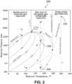
- FIG. 2 is an example phase diagram 200 illustrating the potential phases that can be found in a downhole environment, such as within wellbore 114.
- the well system 100 begins with the phase of produced fluid being point B 2 202.
- Point B 2 202 includes a temperature and pressure where sufficient condensate (liquid) is present to hinder gas flow through the wellbore 114.
- the pressure brings the phase from point B 2 202 to point B 3 204.
- Point B 3 204 includes a temperature and pressure where sufficient condensate (liquid) has been flashed off (liquid has been phase-changed to gas) to allow gas to more freely flow through the wellbore 114.
- the aim is to bring the production point from B 2 202 to B 3 204 at constant temperature (which is the formation temperature).
- a pressure shift can decrease the amount of condensate liquid and therefore free the near production zone 112 from excessive liquid to increase gas production.
- the additional microwave emitter 162 can be used to heat the production fluid, moving the phase of the production fluid from point B 2 202 to point Ai 206.
- Ai 206 is a point where the wellbore 114 produces single-phase gas.
- the pressure change from fluidically exposing the wellbore to the evacuated vacuum chamber 104 can be as high as 2500 pounds per square inch or 17.24 MPa. While described as beginning at point B 2 202, the phase changes described herein are applicable to any point where an amount of condensate is sufficient to reduce production flow.
- the well system includes a controller 300 to, among other things, monitor pressures of the wellbore 114 and send signals to actuate the sleeve 158 or vacuum pump 102.
- the controller 300 can include a processor 302 (implemented as one or more local or distributed processors) and non-transitory storage media (for example, memory 306 - implemented as one or more local or distributed memories) containing instructions that cause the processor 302 to perform the methods described herein.
- the processor 302 is coupled to an input/output (I/O) interface 304 for sending and receiving communications with other equipment of the well system 100 ( FIGS. 1A-1C ) via communication links.
- I/O input/output
- the controller 300 can communicate status with and send actuation and control signals to one or more of the motor 160, the vacuum pump 102, the microwave emitter 162, and other components, such as topside valves, as well as various sensors (such as, pressure sensor 164, temperature sensors, and other types of sensors) at the well site.
- the controller 300 can communicate status and send actuation and control signals to one or more of the systems on at the topside facility 108, such as pumps, compressors, separators, and other equipment on the topside facility 108.
- the communications can be hard-wired, wireless, or a combination of wired and wireless.
- the controller 300 can be located remote from the well system 100, such as in a data van, at the topside facility 108, downhole within the wellbore 114, or even remote from the well system 100 (such as, at a central monitoring facility for monitoring and controlling multiple well sites).
- the controller 300 can be a distributed controller with different portions located about the well system 100 or off site. For example, in certain instances, a portion of the controller 300 can be distributed among individual well system 100 components, while another portion of the controller 300 can be located within a data van or control room.
- the controller 300 can operate in monitoring, controlling, and using the well system 100 for reducing or eliminating a condensate cap within the wellbore 114.
- the controller 300 is used in conjunction with sensors to measure the pressure of fluid within the wellbore 114.
- Input and output signals, including the data from the sensors and actuators, controlled and monitored by the controller 300, can be logged continuously by the controller 300.
- the memory 306 includes instructions for the processor to receive a signal indicative of a wellbore pressure, determine, based on the signal, a presence of a condensate bank or plug, evacuate a vacuum chamber, by a vacuum pump, in response to determining the presence of a condensate bank, and fluidically expose the evacuated vacuum chamber to a wellbore environment.
- a human operator can operate the controller 300, and thus the resulting physical steps, at a safe distance from the high pressure lines, far enough that if there were a leak or failure, the operator would not be injured.
- the operation can be effectuated via a terminal or other control interface associated with the controller 300.
- the operator via controller 300, actuates a fully automated sequence run by the controller 300 to perform the steps described herein (that is, the operator just presses start, or similar, and the controller 300 performs autonomously).
- the operator, via controller 300 commands one or more of the individual, later described steps.
- the terminal can present menu items to the operator that present the operator's options in commanding the controller 300.
- FIG. 4 is a flowchart of an example method 400 that can be used with aspects of this disclosure.
- the vacuum chamber 104 is received by the wellbore 114.
- receiving the vacuum chamber 104 into the wellbore 114 includes receiving the vacuum chamber 104 such that the vacuum chamber 104 is at a depth substantially adjacent to the production zone 112 of the wellbore 114 (within typical field placement error).
- the vacuum chamber 104 is evacuated by the vacuum pump 102.
- the wellbore is fluidically exposed to an interior of the vacuum chamber 104 after the vacuum chamber 104 has been evacuated.
- exposing the wellbore 114 to the interior of the vacuum chamber 104 reduces a pressure within the wellbore by 2500 pounds per square inch (PSI) or 17.24 MPa.
- the pressure drop generated can vary between 500 PSI and 2500 PSI or between 3.45 MPa and 17.24 MPa.
- reducing the pressure from point B 2 202 to point B 3 204 results in a pressure decrease of about 1600 PSI or 11.03 MPa.
- Fluidically exposing the wellbore 114 to an interior of the vacuum chamber 104 includes uncovering openings defined by an outer wall of the vacuum chamber 104, such as the orifice 152.
- At 406 at least a portion of condensate within the wellbore 114 is flashed responsive to fluidically exposing a wellbore 114 to an interior of the evacuated vacuum chamber 104.
- microwaves can be emitted within the wellbore 114 by a microwave emitter 162 positioned within the wellbore.
- at least a portion of condensate within the wellbore 114 is flashed responsive to the emitted microwaves.
- the free gas can be flowed out of the wellbore in sufficient quantity to reduce the likelihood of a condensate cap reforming.
- multiple cycles of evacuation and exposure may be necessary to fully eliminate the condensation cap.
- the vacuum chamber is removed from the wellbore after flashing the condensate.
- the isolation packer 110 can be a removable isolation packer
- the tubular 106 can include coiled tubing, drill pipe, or some other tubular that is easily removed from the wellbore.
- the tubular can be designed to accommodate the permanent operating conditions of the well. For example, improved metallurgy and greater wall thickness can be used in the tubular 106 in a permanent installation.
Landscapes
- Geology (AREA)
- Life Sciences & Earth Sciences (AREA)
- Engineering & Computer Science (AREA)
- Mining & Mineral Resources (AREA)
- Physics & Mathematics (AREA)
- Environmental & Geological Engineering (AREA)
- Fluid Mechanics (AREA)
- General Life Sciences & Earth Sciences (AREA)
- Geochemistry & Mineralogy (AREA)
- Geophysics (AREA)
- Compressors, Vaccum Pumps And Other Relevant Systems (AREA)
- Vaporization, Distillation, Condensation, Sublimation, And Cold Traps (AREA)
- Physical Deposition Of Substances That Are Components Of Semiconductor Devices (AREA)
Claims (15)
- Verfahren (400), das Folgendes umfasst:Evakuieren (402) einer Unterdruckkammer (104) durch eine Unterdruckpumpe (102), wobei die Unterdruckkammer in einem Bohrloch angeordnet ist;fluidtechnisches In-Kontakt-Bringen (404) des Bohrlochs mit einem Innenraum der Unterdruckkammer, nachdem die Unterdruckkammer evakuiert worden ist; gekennzeichnet durchVerdampfen (408) zumindest eines Anteils eines Kondensats im Bohrloch als Antwort auf das fluidtechnische In-Kontakt-Bringen des Bohrlochs mit dem Innenraum der Unterdruckkammer.
- Verfahren nach Anspruch 1, das ferner das Aufnehmen der Unterdruckkammer (104) in das Bohrloch umfasst, wobei das Aufnehmen der Unterdruckkammer in das Bohrloch wahlweise das Aufnehmen der Unterdruckkammer auf eine Weise, dass sich die Unterdruckkammer in einer Tiefe befindet, die ungefähr zu einem Förderhorizont eines Bohrlochs benachbart ist, umfasst.
- Verfahren nach Anspruch 1, wobei das In-Kontakt-Bringen des Bohrlochs mit dem Innenraum der Unterdruckkammer das Verringern eines Drucks im Bohrloch um 17,24 MPa (2500 Pfund pro Quadratzoll) umfasst.
- Verfahren nach Anspruch 1, das ferner das Strömen eines im Wesentlichen freien Gases aus dem Bohrloch umfasst.
- Verfahren nach Anspruch 1, das ferner das Entfernen der Unterdruckkammer (104) aus dem Bohrloch nach dem Verdampfen des Kondensats umfasst.
- Verfahren nach Anspruch 1, wobei das fluidtechnische In-Kontakt-Bringen des Bohrlochs mit einem Innenraum der Unterdruckkammer (104) das Aufdecken von Öffnungen (152), die durch eine Außenwand der Unterdruckkammer definiert sind, umfasst.
- Verfahren nach Anspruch 1, das ferner das Emittieren von Mikrowellen im Bohrloch durch einen Mikrowellensender (162), der im Bohrloch angeordnet ist; und
das Verdampfen zumindest eines Anteils eines Kondensats im Bohrloch als Antwort auf das Emittieren der Mikrowellen umfasst. - Bohrlochsystem, das Folgendes umfasst:eine Unterdruckpumpe (102);eine Unterdruckkammer (104), die mit der Unterdruckpumpe fluidtechnisch verbunden ist, wobei die Unterdruckkammer eine Außenfläche aufweist, die eine Kammer definiert, die mit der Unterdruckpumpe fluidtechnisch gekoppelt ist,wobei die Außenfläche eine betätigbare Öffnung (152) definiert, die zwischen einem offenen Zustand und einem geschlossenen Zustand betätigt werden kann, wobei die Öffnung im offenen Zustand die Kammer und eine Abwärtsbohrlochumgebung fluidtechnisch verbindet und die Öffnung in einem geschlossenen Zustand die Kammer von der Abwärtsbohrlochumgebung fluidtechnisch isoliert;eine Länge eines gewendelten Steigrohrs (106), das die Unterdruckkammer mit einer oberirdischen Anlage (108) fluidtechnisch verbindet; und gekennzeichnet durcheine Steuereinheit (300), die konfiguriert ist zum Empfangen eines Signals, das einen Bohrlochdruck angibt, Bestimmen des Vorhandenseins einer Kondensatbank auf der Grundlage des Signals,Evakuieren der Unterdruckkammer durch die Unterdruckpumpe als Antwort auf das Bestimmen des Vorhandenseins einer Kondensatbank, undfluidtechnisches In-Kontakt-Bringen der evakuierten Unterdruckkammer mit der Abwärtsbohrlochumgebung.
- Bohrlochsystem nach Anspruch 8, wobei i) die Unterdruckpumpe (102) an der oberirdischen Anlage (108) angeordnet ist,wobei die Unterdruckpumpe durch die Länge des gewendelten Steigrohrs (106) mit der Unterdruckkammer (104) fluidtechnisch verbunden ist,oder wobei ii) die Unterdruckpumpe in der Abwärtsbohrlochumgebung angeordnet ist.
- Bohrlochsystem nach Anspruch 8, wobei die betätigbare Öffnung (152) eine Hülse (158) umfasst, die ein Profil definiert, das mit der Außenfläche der Unterdruckkammer übereinstimmt, wobei die Hülse in einer Umfangsrichtung entlang der Fläche der Unterdruckkammer drehbar ist.
- Bohrlochsystem nach Anspruch 10, das ferner einen Motor (160) umfasst, der mit der Hülse (158) gekoppelt ist, wobei der Motor ausgelegt ist, die Hülse zwischen dem offenen Zustand und dem geschlossenen Zustand zu verändern.
- Bohrlochsystem nach Anspruch 8, wobei die Unterdruckkammer (104) und die Länge des gewendelten Steigrohrs (106) in der Abwärtsbohrlochumgebung dauerhaft installiert sind.
- Bohrlochsystem nach Anspruch 8, das ferner Sandabsonderungseinrichtungen an der oberirdischen Anlage (108) umfasst.
- Bohrlochsystem nach Anspruch 10, wobei die Unterdruckpumpe (102) eine Verdrängerpumpe umfasst.
- Bohrlochsystem nach Anspruch 10, wobei die Öffnung (152) ein erste Öffnung ist, das Bohrlochsystem mehrere Öffnungen umfasst, die Öffnungen eine Gesamtströmungsfläche aufweisen, die ausreichend ist, um eine Fluidverbindung zu ermöglichen, und die mehreren Öffnungen jeweils eine Strömungsfläche aufweisen, die klein genug ist, um Sand aus einer Fluidströmung zu filtern.
Applications Claiming Priority (2)
| Application Number | Priority Date | Filing Date | Title |
|---|---|---|---|
| US16/584,174 US11187066B2 (en) | 2019-09-26 | 2019-09-26 | Lifting condensate from wellbores |
| PCT/US2020/052216 WO2021061772A1 (en) | 2019-09-26 | 2020-09-23 | Lifting condensate from wellbores |
Publications (2)
| Publication Number | Publication Date |
|---|---|
| EP4034748A1 EP4034748A1 (de) | 2022-08-03 |
| EP4034748B1 true EP4034748B1 (de) | 2024-11-27 |
Family
ID=72811959
Family Applications (1)
| Application Number | Title | Priority Date | Filing Date |
|---|---|---|---|
| EP20789332.2A Active EP4034748B1 (de) | 2019-09-26 | 2020-09-23 | Heben von kondensat aus bohrlöchern |
Country Status (4)
| Country | Link |
|---|---|
| US (1) | US11187066B2 (de) |
| EP (1) | EP4034748B1 (de) |
| SA (1) | SA522432068B1 (de) |
| WO (1) | WO2021061772A1 (de) |
Families Citing this family (4)
| Publication number | Priority date | Publication date | Assignee | Title |
|---|---|---|---|---|
| US12049801B2 (en) * | 2022-03-11 | 2024-07-30 | Caterpillar Inc. | Controlling operations of a hydraulic fracturing system to cause or prevent an occurrence of one or more events |
| US11939851B2 (en) | 2022-08-09 | 2024-03-26 | Saudi Arabian Oil Company | Microwave heating technique for treatment of condensate buildup |
| US12188330B2 (en) | 2022-08-09 | 2025-01-07 | Saudi Arabian Oil Company | Treatment of organic deposits using microwave heating |
| US12416738B2 (en) | 2022-10-03 | 2025-09-16 | Saudi Arabian Oil Company | Method for iterative first arrival picking using global path tracing |
Family Cites Families (8)
| Publication number | Priority date | Publication date | Assignee | Title |
|---|---|---|---|---|
| US4370886A (en) | 1981-03-20 | 1983-02-01 | Halliburton Company | In situ measurement of gas content in formation fluid |
| US4369839A (en) * | 1981-08-17 | 1983-01-25 | F & P Production Co., Inc. | Casing vacuum system |
| US20040129428A1 (en) | 2002-12-20 | 2004-07-08 | Kelley Terry Earl | Plunger lift deliquefying system for increased recovery from oil and gas wells |
| WO2008006880A1 (en) | 2006-07-14 | 2008-01-17 | Shell Internationale Research Maatschappij B.V. | A method of controlling water condensation in a near wellbore region of a formation |
| US9464854B2 (en) | 2013-02-01 | 2016-10-11 | Dell Products, Lp | Techniques for controlling vapor pressure in an immersion cooling tank |
| US9243474B2 (en) | 2014-04-02 | 2016-01-26 | Halliburton Energy Services, Inc. | Using dynamic underbalance to increase well productivity |
| US10053959B2 (en) | 2015-05-05 | 2018-08-21 | Saudi Arabian Oil Company | System and method for condensate blockage removal with ceramic material and microwaves |
| US10718747B2 (en) * | 2017-06-23 | 2020-07-21 | Halliburton Energy Services, Inc. | Detection of inorganic gases |
-
2019
- 2019-09-26 US US16/584,174 patent/US11187066B2/en active Active
-
2020
- 2020-09-23 WO PCT/US2020/052216 patent/WO2021061772A1/en not_active Ceased
- 2020-09-23 EP EP20789332.2A patent/EP4034748B1/de active Active
-
2022
- 2022-03-24 SA SA522432068A patent/SA522432068B1/ar unknown
Also Published As
| Publication number | Publication date |
|---|---|
| US11187066B2 (en) | 2021-11-30 |
| SA522432068B1 (ar) | 2024-08-21 |
| WO2021061772A1 (en) | 2021-04-01 |
| EP4034748A1 (de) | 2022-08-03 |
| US20210095544A1 (en) | 2021-04-01 |
Similar Documents
| Publication | Publication Date | Title |
|---|---|---|
| EP4034748B1 (de) | Heben von kondensat aus bohrlöchern | |
| US6179056B1 (en) | Artificial lift, concentric tubing production system for wells and method of using same | |
| US10563481B2 (en) | Remotely operated and multi-functional down-hole control tools | |
| US6595295B1 (en) | Electric submersible pump assembly | |
| CA2302538C (en) | Production tubing shunt valve | |
| US6237692B1 (en) | Gas displaced chamber lift system having a double chamber | |
| US10584563B2 (en) | Remotely operated and multi-functional down-hole control tools | |
| US6533037B2 (en) | Flow-operated valve | |
| US10619450B2 (en) | Remotely operated and multi-functional down-hole control tools | |
| EP1191185A1 (de) | Bohrlochzentrifugalseparator und Bedienungsverfahren desselben | |
| US20040129419A1 (en) | Rigless one-trip system | |
| CA3047561A1 (en) | Downhole solid state pumps | |
| CN105934559A (zh) | 转换阀系统及用于采气的方法 | |
| US11851974B1 (en) | Resettable packer system for pumping operations | |
| NO20210110A1 (en) | Well Operation Optimization | |
| NO20201133A1 (en) | Dual line hydraulic control system to operate multiple downhole valves | |
| US4498541A (en) | Method of well completion | |
| US10233732B2 (en) | Active integrated flow control for completion system | |
| WO2021029786A1 (ru) | Способ поинтервального воздействия на горизонтальные скважины | |
| CA3060000C (en) | Dual-walled coiled tubing with downhole flow actuated pump | |
| RU2835485C1 (ru) | Пакер входного модуля скважинного насоса с электрическим приводом | |
| US11492880B2 (en) | Gas operated, retrievable well pump for assisting gas lift | |
| EA043470B1 (ru) | Способ поинтервального воздействия на горизонтальные скважины, эксплуатируемые глубинно-насосным оборудованием, и устройство для его осуществления |
Legal Events
| Date | Code | Title | Description |
|---|---|---|---|
| STAA | Information on the status of an ep patent application or granted ep patent |
Free format text: STATUS: UNKNOWN |
|
| STAA | Information on the status of an ep patent application or granted ep patent |
Free format text: STATUS: THE INTERNATIONAL PUBLICATION HAS BEEN MADE |
|
| PUAI | Public reference made under article 153(3) epc to a published international application that has entered the european phase |
Free format text: ORIGINAL CODE: 0009012 |
|
| STAA | Information on the status of an ep patent application or granted ep patent |
Free format text: STATUS: REQUEST FOR EXAMINATION WAS MADE |
|
| 17P | Request for examination filed |
Effective date: 20220330 |
|
| AK | Designated contracting states |
Kind code of ref document: A1 Designated state(s): AL AT BE BG CH CY CZ DE DK EE ES FI FR GB GR HR HU IE IS IT LI LT LU LV MC MK MT NL NO PL PT RO RS SE SI SK SM TR |
|
| DAV | Request for validation of the european patent (deleted) | ||
| DAX | Request for extension of the european patent (deleted) | ||
| P01 | Opt-out of the competence of the unified patent court (upc) registered |
Effective date: 20230528 |
|
| GRAP | Despatch of communication of intention to grant a patent |
Free format text: ORIGINAL CODE: EPIDOSNIGR1 |
|
| STAA | Information on the status of an ep patent application or granted ep patent |
Free format text: STATUS: GRANT OF PATENT IS INTENDED |
|
| INTG | Intention to grant announced |
Effective date: 20240703 |
|
| GRAS | Grant fee paid |
Free format text: ORIGINAL CODE: EPIDOSNIGR3 |
|
| GRAA | (expected) grant |
Free format text: ORIGINAL CODE: 0009210 |
|
| STAA | Information on the status of an ep patent application or granted ep patent |
Free format text: STATUS: THE PATENT HAS BEEN GRANTED |
|
| AK | Designated contracting states |
Kind code of ref document: B1 Designated state(s): AL AT BE BG CH CY CZ DE DK EE ES FI FR GB GR HR HU IE IS IT LI LT LU LV MC MK MT NL NO PL PT RO RS SE SI SK SM TR |
|
| REG | Reference to a national code |
Ref country code: GB Ref legal event code: FG4D |
|
| REG | Reference to a national code |
Ref country code: CH Ref legal event code: EP |
|
| REG | Reference to a national code |
Ref country code: IE Ref legal event code: FG4D |
|
| REG | Reference to a national code |
Ref country code: DE Ref legal event code: R096 Ref document number: 602020042132 Country of ref document: DE |
|
| REG | Reference to a national code |
Ref country code: LT Ref legal event code: MG9D |
|
| REG | Reference to a national code |
Ref country code: NL Ref legal event code: MP Effective date: 20241127 |
|
| PG25 | Lapsed in a contracting state [announced via postgrant information from national office to epo] |
Ref country code: PT Free format text: LAPSE BECAUSE OF FAILURE TO SUBMIT A TRANSLATION OF THE DESCRIPTION OR TO PAY THE FEE WITHIN THE PRESCRIBED TIME-LIMIT Effective date: 20250327 Ref country code: HR Free format text: LAPSE BECAUSE OF FAILURE TO SUBMIT A TRANSLATION OF THE DESCRIPTION OR TO PAY THE FEE WITHIN THE PRESCRIBED TIME-LIMIT Effective date: 20241127 Ref country code: IS Free format text: LAPSE BECAUSE OF FAILURE TO SUBMIT A TRANSLATION OF THE DESCRIPTION OR TO PAY THE FEE WITHIN THE PRESCRIBED TIME-LIMIT Effective date: 20250327 |
|
| PG25 | Lapsed in a contracting state [announced via postgrant information from national office to epo] |
Ref country code: NL Free format text: LAPSE BECAUSE OF FAILURE TO SUBMIT A TRANSLATION OF THE DESCRIPTION OR TO PAY THE FEE WITHIN THE PRESCRIBED TIME-LIMIT Effective date: 20241127 Ref country code: FI Free format text: LAPSE BECAUSE OF FAILURE TO SUBMIT A TRANSLATION OF THE DESCRIPTION OR TO PAY THE FEE WITHIN THE PRESCRIBED TIME-LIMIT Effective date: 20241127 |
|
| REG | Reference to a national code |
Ref country code: AT Ref legal event code: MK05 Ref document number: 1745864 Country of ref document: AT Kind code of ref document: T Effective date: 20241127 |
|
| PG25 | Lapsed in a contracting state [announced via postgrant information from national office to epo] |
Ref country code: BG Free format text: LAPSE BECAUSE OF FAILURE TO SUBMIT A TRANSLATION OF THE DESCRIPTION OR TO PAY THE FEE WITHIN THE PRESCRIBED TIME-LIMIT Effective date: 20241127 |
|
| PG25 | Lapsed in a contracting state [announced via postgrant information from national office to epo] |
Ref country code: ES Free format text: LAPSE BECAUSE OF FAILURE TO SUBMIT A TRANSLATION OF THE DESCRIPTION OR TO PAY THE FEE WITHIN THE PRESCRIBED TIME-LIMIT Effective date: 20241127 |
|
| PG25 | Lapsed in a contracting state [announced via postgrant information from national office to epo] |
Ref country code: LV Free format text: LAPSE BECAUSE OF FAILURE TO SUBMIT A TRANSLATION OF THE DESCRIPTION OR TO PAY THE FEE WITHIN THE PRESCRIBED TIME-LIMIT Effective date: 20241127 Ref country code: GR Free format text: LAPSE BECAUSE OF FAILURE TO SUBMIT A TRANSLATION OF THE DESCRIPTION OR TO PAY THE FEE WITHIN THE PRESCRIBED TIME-LIMIT Effective date: 20250228 Ref country code: AT Free format text: LAPSE BECAUSE OF FAILURE TO SUBMIT A TRANSLATION OF THE DESCRIPTION OR TO PAY THE FEE WITHIN THE PRESCRIBED TIME-LIMIT Effective date: 20241127 |
|
| PG25 | Lapsed in a contracting state [announced via postgrant information from national office to epo] |
Ref country code: PL Free format text: LAPSE BECAUSE OF FAILURE TO SUBMIT A TRANSLATION OF THE DESCRIPTION OR TO PAY THE FEE WITHIN THE PRESCRIBED TIME-LIMIT Effective date: 20241127 |
|
| PG25 | Lapsed in a contracting state [announced via postgrant information from national office to epo] |
Ref country code: RS Free format text: LAPSE BECAUSE OF FAILURE TO SUBMIT A TRANSLATION OF THE DESCRIPTION OR TO PAY THE FEE WITHIN THE PRESCRIBED TIME-LIMIT Effective date: 20250227 |
|
| PG25 | Lapsed in a contracting state [announced via postgrant information from national office to epo] |
Ref country code: SM Free format text: LAPSE BECAUSE OF FAILURE TO SUBMIT A TRANSLATION OF THE DESCRIPTION OR TO PAY THE FEE WITHIN THE PRESCRIBED TIME-LIMIT Effective date: 20241127 |
|
| PG25 | Lapsed in a contracting state [announced via postgrant information from national office to epo] |
Ref country code: DK Free format text: LAPSE BECAUSE OF FAILURE TO SUBMIT A TRANSLATION OF THE DESCRIPTION OR TO PAY THE FEE WITHIN THE PRESCRIBED TIME-LIMIT Effective date: 20241127 |
|
| PG25 | Lapsed in a contracting state [announced via postgrant information from national office to epo] |
Ref country code: EE Free format text: LAPSE BECAUSE OF FAILURE TO SUBMIT A TRANSLATION OF THE DESCRIPTION OR TO PAY THE FEE WITHIN THE PRESCRIBED TIME-LIMIT Effective date: 20241127 |
|
| PG25 | Lapsed in a contracting state [announced via postgrant information from national office to epo] |
Ref country code: RO Free format text: LAPSE BECAUSE OF FAILURE TO SUBMIT A TRANSLATION OF THE DESCRIPTION OR TO PAY THE FEE WITHIN THE PRESCRIBED TIME-LIMIT Effective date: 20241127 |
|
| PG25 | Lapsed in a contracting state [announced via postgrant information from national office to epo] |
Ref country code: SK Free format text: LAPSE BECAUSE OF FAILURE TO SUBMIT A TRANSLATION OF THE DESCRIPTION OR TO PAY THE FEE WITHIN THE PRESCRIBED TIME-LIMIT Effective date: 20241127 |
|
| PG25 | Lapsed in a contracting state [announced via postgrant information from national office to epo] |
Ref country code: CZ Free format text: LAPSE BECAUSE OF FAILURE TO SUBMIT A TRANSLATION OF THE DESCRIPTION OR TO PAY THE FEE WITHIN THE PRESCRIBED TIME-LIMIT Effective date: 20241127 |
|
| PG25 | Lapsed in a contracting state [announced via postgrant information from national office to epo] |
Ref country code: IT Free format text: LAPSE BECAUSE OF FAILURE TO SUBMIT A TRANSLATION OF THE DESCRIPTION OR TO PAY THE FEE WITHIN THE PRESCRIBED TIME-LIMIT Effective date: 20241127 |
|
| REG | Reference to a national code |
Ref country code: DE Ref legal event code: R097 Ref document number: 602020042132 Country of ref document: DE |
|
| PG25 | Lapsed in a contracting state [announced via postgrant information from national office to epo] |
Ref country code: SE Free format text: LAPSE BECAUSE OF FAILURE TO SUBMIT A TRANSLATION OF THE DESCRIPTION OR TO PAY THE FEE WITHIN THE PRESCRIBED TIME-LIMIT Effective date: 20241127 |
|
| PLBE | No opposition filed within time limit |
Free format text: ORIGINAL CODE: 0009261 |
|
| STAA | Information on the status of an ep patent application or granted ep patent |
Free format text: STATUS: NO OPPOSITION FILED WITHIN TIME LIMIT |
|
| PGFP | Annual fee paid to national office [announced via postgrant information from national office to epo] |
Ref country code: NO Payment date: 20250909 Year of fee payment: 6 |
|
| 26N | No opposition filed |
Effective date: 20250828 |