EP4034682B1 - Direct reduction process utilizing hydrogen - Google Patents
Direct reduction process utilizing hydrogen Download PDFInfo
- Publication number
- EP4034682B1 EP4034682B1 EP20797244.9A EP20797244A EP4034682B1 EP 4034682 B1 EP4034682 B1 EP 4034682B1 EP 20797244 A EP20797244 A EP 20797244A EP 4034682 B1 EP4034682 B1 EP 4034682B1
- Authority
- EP
- European Patent Office
- Prior art keywords
- hydrogen
- gas stream
- direct reduction
- gas
- carbon
- Prior art date
- Legal status (The legal status is an assumption and is not a legal conclusion. Google has not performed a legal analysis and makes no representation as to the accuracy of the status listed.)
- Active
Links
Images

Classifications
-
- C—CHEMISTRY; METALLURGY
- C21—METALLURGY OF IRON
- C21B—MANUFACTURE OF IRON OR STEEL
- C21B11/00—Making pig-iron other than in blast furnaces
- C21B11/02—Making pig-iron other than in blast furnaces in low shaft furnaces or shaft furnaces
-
- C—CHEMISTRY; METALLURGY
- C21—METALLURGY OF IRON
- C21B—MANUFACTURE OF IRON OR STEEL
- C21B13/00—Making spongy iron or liquid steel, by direct processes
- C21B13/0073—Selection or treatment of the reducing gases
-
- C—CHEMISTRY; METALLURGY
- C21—METALLURGY OF IRON
- C21B—MANUFACTURE OF IRON OR STEEL
- C21B13/00—Making spongy iron or liquid steel, by direct processes
- C21B13/02—Making spongy iron or liquid steel, by direct processes in shaft furnaces
-
- C—CHEMISTRY; METALLURGY
- C21—METALLURGY OF IRON
- C21B—MANUFACTURE OF IRON OR STEEL
- C21B2100/00—Handling of exhaust gases produced during the manufacture of iron or steel
- C21B2100/20—Increasing the gas reduction potential of recycled exhaust gases
- C21B2100/22—Increasing the gas reduction potential of recycled exhaust gases by reforming
-
- C—CHEMISTRY; METALLURGY
- C21—METALLURGY OF IRON
- C21B—MANUFACTURE OF IRON OR STEEL
- C21B2100/00—Handling of exhaust gases produced during the manufacture of iron or steel
- C21B2100/20—Increasing the gas reduction potential of recycled exhaust gases
- C21B2100/24—Increasing the gas reduction potential of recycled exhaust gases by shift reactions
-
- C—CHEMISTRY; METALLURGY
- C21—METALLURGY OF IRON
- C21B—MANUFACTURE OF IRON OR STEEL
- C21B2100/00—Handling of exhaust gases produced during the manufacture of iron or steel
- C21B2100/20—Increasing the gas reduction potential of recycled exhaust gases
- C21B2100/26—Increasing the gas reduction potential of recycled exhaust gases by adding additional fuel in recirculation pipes
-
- C—CHEMISTRY; METALLURGY
- C21—METALLURGY OF IRON
- C21B—MANUFACTURE OF IRON OR STEEL
- C21B2100/00—Handling of exhaust gases produced during the manufacture of iron or steel
- C21B2100/40—Gas purification of exhaust gases to be recirculated or used in other metallurgical processes
- C21B2100/44—Removing particles, e.g. by scrubbing, dedusting
-
- C—CHEMISTRY; METALLURGY
- C21—METALLURGY OF IRON
- C21C—PROCESSING OF PIG-IRON, e.g. REFINING, MANUFACTURE OF WROUGHT-IRON OR STEEL; TREATMENT IN MOLTEN STATE OF FERROUS ALLOYS
- C21C2200/00—Recycling of waste material
-
- Y—GENERAL TAGGING OF NEW TECHNOLOGICAL DEVELOPMENTS; GENERAL TAGGING OF CROSS-SECTIONAL TECHNOLOGIES SPANNING OVER SEVERAL SECTIONS OF THE IPC; TECHNICAL SUBJECTS COVERED BY FORMER USPC CROSS-REFERENCE ART COLLECTIONS [XRACs] AND DIGESTS
- Y02—TECHNOLOGIES OR APPLICATIONS FOR MITIGATION OR ADAPTATION AGAINST CLIMATE CHANGE
- Y02P—CLIMATE CHANGE MITIGATION TECHNOLOGIES IN THE PRODUCTION OR PROCESSING OF GOODS
- Y02P10/00—Technologies related to metal processing
- Y02P10/10—Reduction of greenhouse gas [GHG] emissions
- Y02P10/143—Reduction of greenhouse gas [GHG] emissions of methane [CH4]
Definitions
- the present disclosure relates generally to the direct reduction (DR) and steelmaking fields. More particularly, the present disclosure relates a method and system for converting a DR process, such as a MIDREX process or the like, utilizing natural gas to a DR process utilizing a variable mixture of natural gas (NG) and hydrogen (H2), resulting in direct reduced iron (DRI) having reduced carbon content and lower overall carbon dioxide (CO2) emissions.
- a DR process such as a MIDREX process or the like
- NG variable mixture of natural gas
- H2 hydrogen
- DRI direct reduced iron
- CO2 carbon dioxide
- the current MIDREX NG and similar processes utilize a highly-optimized reformer to generate syngas from NG for the reduction of iron ore. Such processes emit a large amount of CO2 due to the presence of carbon in the NG.
- Specific efforts are sought to decarbonize parts of the steel industry, as different regions look to reduce their CO 2 emissions.
- One such effort is to replace feed NG with H2. While other methods and systems exist to do this, most require a total upfront replacement of both the reducing gas source and equipment. This places considerable limits on the adoption of H2 as the reducing gas source, as H2 is not yet economically viable and there exist significant uncertainties in the timeline and growth of the H2 supply.
- One key challenge is that the H2 supply may be subject to fluctuations of renewable energy sources, such as solar and wind.
- the problems to be solved include: operating a conventional DR NG plant with an intermittent H2 supply; effectively transitioning existing DR NG plants to H2-based reduction; and protecting equipment during such transitions.
- Examples of direct reduction processes and apparatuses of the filed are WO 2013/093640 A2 , US 2013/205951 A1 and WO 2014/040990 A2 .
- the present disclosure provides a direct reduction method according to claim 1
- the feed gas stream includes a top gas stream recycled from the shaft furnace.
- the method also includes one or more of wet scrubbing and compressing the top gas stream.
- the method includes adding the variable amounts of the natural gas, the hydrogen, and the carbon-free oxidizing gas to the feed gas stream upstream of the reformer and a preheater disposed upstream of the reformer.
- the carbon-free oxidizing gas includes steam.
- the method further includes controlling a flow rate of the steam to maintain a maximum k-factor value of the feed gas stream of 0.74 or lower.
- the variable amount of hydrogen is selected to replace 20-90% of the natural gas by fuel value.
- variable amount of hydrogen is selected to replace 30-70% of the natural gas by fuel value.
- the variable amount of hydrogen is selected based upon an available supply of hydrogen.
- the variable amount of hydrogen is selected based upon the available supply of hydrogen from a renewable hydrogen source.
- the system also includes one or more of wet scrubber operable for wet scrubbing and a compressor operable for compressing the top gas stream.
- the external gas sources are operable for adding the variable amounts of the natural gas, the hydrogen, and the carbon-free oxidizing gas to the feed gas stream upstream of the reformer and a preheater disposed upstream of the reformer.
- the carbon-free oxidizing gas includes steam.
- the system further includes a flow controller operable for controlling a flow rate of the steam to maintain a maximum k-factor value of the feed gas stream of 0.74 or lower.
- variable amount of hydrogen is selected to replace 20-90% of the natural gas by fuel value.
- variable amount of hydrogen is selected to replace 30-70% of the natural gas by fuel value.
- the variable amount of hydrogen is selected based upon an available supply of hydrogen.
- variable amount of hydrogen is selected based upon the available supply of hydrogen from a renewable hydrogen source.
- the hydrogen and natural gas ratios are determined by the total energy requirements to produce DRI at a specified product quality and the availability of hydrogen.
- the typical product qualities that are controlled for are percent metallization, that is the amount of metallic iron as a percent by weight of the total iron, and product carbon, that is the amount of carbon in the product by weight percent.
- Sufficient flow of gas in the inlet feed is required to ensure that reducing gas quality is maintained and energy requirements are met in the furnace to drive the reducing reactions to achieve metallization.
- the percent metallization is the main driver as it determines the amount of reductant required to remove the oxygen from the iron oxide.
- the total process energy requirements, including carbon addition account for ⁇ 70% of the energy required. The remaining ⁇ 30% is mainly sensible heat losses from various process steps, such as at the top gas scrubber or from the flue gas stack.
- the combination and selection of the natural gas and hydrogen flowrate will depend on hydrogen availability, costs associated with CO2 emissions, and desired product carbon.
- the present disclosure relates generally to an improvement of the Midrex NG and similar processes for the reduction of iron ores.
- the overall process described herein presents modifications to the associated plants that allow for on-stream variation of the fuel gas source for the reducing gas feed.
- H2 gas is fed interchangeably with NG to the process depending on hour-to-hour changes in H2 availability. This process stands in contrast with other processes designed for specific fuel compositions.
- Iron oxide 11 enters via the top of the shaft furnace 120, where it reduces to DRI from reactions with H2 and carbon monoxide (CO).
- the DRI leaves the shaft furnace via gravity as cold DRI (CDRI), hot DRI (HDRI), hot briquetted iron (HBI), etc. 50.
- CDRI cold DRI
- HDRI hot DRI
- HBI hot briquetted iron
- the top gas 12 is split into two streams; process gas 13 and top gas fuel 16.
- the process gas 13 is recycled and compressed in a compressor 140, to pressure of about 2.0 bar g with a temperature of about 150 °C.
- NG 14, H2 22, and steam 21 are then added to the process gas 13.
- the NG 14 has a temperature of about 25 °C
- the H2 22 has a temperature of about 25 °C
- the steam 21 has a temperature of about 300 °C.
- This feed gas 15 is preheated to a temperature of about 560 °C in a heat recovery unit 150 and the preheated feed gas 17 is sent to the reformer 160.
- the top gas fuel 16 is used as burner fuel 18 for the reformer 160 or optionally the steam boiler 170.
- external gases 14, 22, and 21 are added to the feed gas 15 and are mixed into the feed gas 15 upstream of the heat recovery unit 150, but they can also be fed into the preheated feed gas stream 17 downstream of the heat recovery unit 150, and upstream of the reformer 160.
- the flow of steam 21 is controlled based on the inlet chemistry of the preheated feed gas stream 17 at the inlet of the reformer 160 and adjusts depending on the availability of H2 22.
- the preferred chemistry of the preheated feed gas stream 17 at the inlet of the reformer 160 is mixture of hydrogen, carbon monoxide, carbon dioxide, water and natural gas, with a temperature of about 450 - 600 °C and a pressure of about 1.6 - 1.9 bar g.
- the preferred chemistry of the reformed gas 19 at the outlet of the reformer 160 is predominately hydrogen and carbon monoxide, with a gas quality of > 10, a temperature of about 850 - 1000 °C and a pressure of about 1.7 - 2.0 bar g.
- the amount of NG 14 added to the feed gas 15 is based on the total energy requirements to produce DRI at the specified production rate and quality.
- the amount of H2 22 added to the feed gas 15 is based on availability of the hydrogen source and the energy requirements to produce DRI at the specified production rate and quality.
- the amount of steam 21 added to the feed gas 15 is based on chemistry requirements to prevent carbon degradation at the inlet of the reformer.
- These additions of external gases 14, 22, and 21 are variable and may fluctuate based on chemistry preferences and H2 22 availability in general.
- the feed mix composition of natural gas 14 and hydrogen 22 is determined by the total energy requirements of the reduction process and to a lesser extent the flows required to tailor the product carbon. For the conventional natural gas based process, the energy needed is about 2.5 net Gcal per ton product.
- a mol of hydrogen replaces roughly 0.3 mols of natural gas due to their differing net heating values of 2500 kcal / Nm3 for hydrogen and 8500 kcal / Nm3 for natural gas.
- energy is no longer needed for the reforming of natural gas and the total requirement approaches about 1.8 net Gcal per ton product with full replacement.
- a flow of 440 Nm 3 of hydrogen per ton product is able to supply ⁇ 50% of the new total energy requirement to produce one ton of DRI.
- the remaining ⁇ 50% of the energy is supplied by natural gas at a rate of ⁇ 140 Nm 3 of natural gas per ton product.
- ratios can be selected via similar means depending on the hour to hour availability of hydrogen.
- An example subsystem is transition zone natural gas addition, or natural gas that is added directly to the shaft furnace below the bustle.
- the transition zone natural gas flowrate can vary greatly from 10 - 60 Nm 3 of natural gas per ton product depending on desired product carbon, solid feed material carburizing characteristics and furnace operation.
- a similar range of natural gas is required even as hydrogen is added to the process. Since carbon deposition is dependent on the methane and CO concentrations, in some cases the natural gas feed may increase in these systems to maintain the same product carbon.
- the process of the present disclosure has key advantages over conventional reduction processes.
- the conventional NG process requires tight control of feed flow and composition. Abrupt changes can have dire effects on the plant: clustering in the shaft furnace, reformer tube degradation, etc. The most significant of these is the catastrophic deactivation of catalyst that occurs when carbon deposits on and physically breaks down the catalyst.
- the controlled introduction of water vapor to the feed gas mitigates the above effects while minimizing disruption to product iron quality.
- This allows multiple varying reducing feed gas sources, for example NG and H2, to be used simultaneously when availability is not constant for one or both.
- Positive effects of this include helping existing NG-based reduction technologies realize the utilization of H2 from renewable sources as a method for reducing CO2 emissions.
- the present disclosure can be used in different scenarios, such as: H2 sources that have variable production rates, such as solar or wind-based H2 generation; or the stepwise implementation of fixed H2 production, such as electrolysis. This allows for flexibility in the fuel source that existing NG-based plants can use; specifically H2 from green sources where supply will vary based on daily changes, such as solar or wind.
- NG is generally reformed into syngas, which in turn reacts with iron oxide to product DRI.
- the basic methane reforming reactions are: CH 4 + H 2 O ⁇ CO + 3H 2 (1) CH 4 + CO 2 ⁇ 2CO + 2H 2 (2)
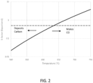
- Equation (4) Because of equation (4), the presence of H2 or CO increases the favorability of carbon. Water, on the other hand, prevents the formation of carbon. CO2 tends to have little effect on shifting carbon favorability because it reacts with methane to produce CO, thereby nullifying its response as an oxidant.
- MIDREX has developed a simplified version of the equilibrium constant as defined in equation (6).
- the reformer inlet operates within the region where carbon deposition is thermodynamically favored.
- This method of operation requires fine control over the temperature and composition of the inlet gas to prevent carbon deposition from occurring.
- the catalyst undergoes a sulfur passivation process to decrease its activity at the tube inlet, where the carbon reactions are heavily favored due to the lower temperature. Lower activity allows the feed gas to remain out of equilibrium until the gas has sufficiently heated to no longer favor carbon deposition. Because the system is out of equilibrium, each carbon reaction must be evaluated separately for safe operation of the reformer.
- equation (4) is the most constraining.
- the MIDREX reformer operates with a k-factor of 0.5 (dashed line) for the NG-based flowsheet.
- the carbon deposit region is favored by equilibrium in the ⁇ 650 °C region of FIG. 2 , which is a typical temperature region of feed gas preheats.
- water content is determined by the saturation condition at the process gas scrubber.
- process water is used to dedust, cool, and condense excess water from the top gas.
- the operating temperature is typically in the range of 55 - 65 °C. This limits the amount of water present in the process gas, which in turn limits the amount of H2 that can be added and achieve k-factors below 0.7.
- H2 water needs to be added than can be achieved from the conventional scrubber operating condition.
- the conventional MIDREX NG flowsheet can handle a maximum of 200 Nm 3 of H2 per ton DRI produced to the process loop without adverse effects at the reformer.
- the steam generation system adds stream directly to the process gas.
- This steam addition allows for the feed gas water composition to be maintained directly, independent of the top gas scrubber dust removal requirements.
- the present disclosure can freely change between low, medium and high addition of H2 dependent on the availability from an external supply, unlike the conventional process.
- FIG. 1 illustrates the steam generation system.
- the steam requirements are low pressure steam, 5 bar g, with a temperature of > 160°C. If any external sources of such steam are available, then the steam generation system is not required. The location in FIG.
- steam addition is the preferred location of the steam addition; downstream of the process gas compressor and upstream of the reformer, but so long as steam is added upstream of the reformer and achieves good mixing then the addition is acceptable.
- the steam addition allows for this embodiment to provide sufficient water to create a steady value for the k-factor even with hydrogen additions in excess of 200 Nm 3 of hydrogen per ton product. Further, control action for steam valves allows for quick and precise control of the water content to take full advantage of changes in H2 availability throughout the day.
- the present disclosure requires additional changes to equipment design and control requirements. Specifically, the process gas compressor and heat recovery unit are greatly impacted. Solutions to these problems already exist in the art and are worth mentioning here. As H2 is added, the reduction reactions become more endothermic. With a fixed energy requirement to achieve the same DRI quality (metallization, carbon, etc.), the endothermic H2 reactions in the furnace require more sensible heat than would normally be provided by reaction heat due to the CO reduction reactions. This means that the reducing gas flowrate needs to increase as H2 is added as the reducing gas temperature is limited by what the solid material (DRI) can handle (typically ⁇ 900 °C is the maximum achievable bed temperature before clustering becomes an issue).
- DRI solid material
- the plant heat recovery is affected due to the decreased flue gas from the reformer.
- the main driver for this effect is that, as external hydrogen is added, less reforming is required.
- the net result is that the fuel gas flowrate (post-combustion top gas fuel and burner natural gas) decreases as hydrogen is added.
- the heat recovery unit is a series of tubular heat exchangers, each with fixed heat transfer coefficients and areas. As the flue gas flowrate decreases, the amount of recoverable waste heat also decreases, thus, due to the fixed heat transfer geometry, the preheats of the various process streams, such as feed gas, also decrease.
- a major consideration in the conventional MIDREX NG process and the heat recovery design is to maintain a flue gas stack temperature of > 180 °C, ideally above 250 °C, to protect downstream equipment, such as hot fans, from the detrimental effects of acid gases, such as H2SO4, that can develop at these lower temperatures. This consideration is still required, as H2 is added to the flowsheet because sulfur is removed from the solid product in the reduction process, so these acid gas reactions can still occur.
- the solution to the changing fuel source for the heat recovery piece of equipment includes individual bundle bypass or dilution air in order to maintain proper bundle and stack temperatures.
- the transition period between NG-based reduction and H2-based reduction requires unique considerations if existing facilities want to take advantage of decreasing CO2 emissions via external H2.
- the current embodiment considers these types of process and equipment constraints in order to fully utilize H2 addition to a conventional MIDREX NG plant or the like.
- the present disclosure allows the conventional MIDREX NG flowsheet or the like to operate with intermittent hydrogen availability with the possibility to convert to complete H2-based reduction capabilities.
Landscapes
- Engineering & Computer Science (AREA)
- Chemical & Material Sciences (AREA)
- Manufacturing & Machinery (AREA)
- Materials Engineering (AREA)
- Metallurgy (AREA)
- Organic Chemistry (AREA)
- Hydrogen, Water And Hydrids (AREA)
- Manufacture Of Iron (AREA)
- Manufacture And Refinement Of Metals (AREA)
Applications Claiming Priority (3)
| Application Number | Priority Date | Filing Date | Title |
|---|---|---|---|
| US201962906954P | 2019-09-27 | 2019-09-27 | |
| US17/029,778 US11952638B2 (en) | 2019-09-27 | 2020-09-23 | Direct reduction process utilizing hydrogen |
| PCT/US2020/052373 WO2021061896A1 (en) | 2019-09-27 | 2020-09-24 | Direct reduction process utilizing hydrogen |
Publications (3)
| Publication Number | Publication Date |
|---|---|
| EP4034682A1 EP4034682A1 (en) | 2022-08-03 |
| EP4034682C0 EP4034682C0 (en) | 2025-05-28 |
| EP4034682B1 true EP4034682B1 (en) | 2025-05-28 |
Family
ID=75162948
Family Applications (1)
| Application Number | Title | Priority Date | Filing Date |
|---|---|---|---|
| EP20797244.9A Active EP4034682B1 (en) | 2019-09-27 | 2020-09-24 | Direct reduction process utilizing hydrogen |
Country Status (11)
| Country | Link |
|---|---|
| US (1) | US11952638B2 (pl) |
| EP (1) | EP4034682B1 (pl) |
| CN (1) | CN114423875A (pl) |
| AR (1) | AR120100A1 (pl) |
| CA (1) | CA3151730C (pl) |
| ES (1) | ES3033551T3 (pl) |
| MX (1) | MX2022003488A (pl) |
| MY (1) | MY207754A (pl) |
| PL (1) | PL4034682T3 (pl) |
| UA (1) | UA127675C2 (pl) |
| WO (1) | WO2021061896A1 (pl) |
Families Citing this family (8)
| Publication number | Priority date | Publication date | Assignee | Title |
|---|---|---|---|---|
| CN113355474A (zh) * | 2021-05-25 | 2021-09-07 | 江阴市尚疯新能源技术开发有限公司 | 一种用铁矿、氢气、氧气炼钢铁碳中和的方法 |
| LU500245B1 (en) * | 2021-06-03 | 2022-12-07 | Wurth Paul Sa | Method for operating a blast furnace installation |
| JP7264313B1 (ja) * | 2021-06-15 | 2023-04-25 | Jfeスチール株式会社 | シャフト炉の操業方法及び還元鉄の製造方法 |
| CN113373274B (zh) * | 2021-06-15 | 2023-01-31 | 中冶赛迪工程技术股份有限公司 | 用于全氢竖炉的煤气处理工艺 |
| EP4273271A1 (de) * | 2022-05-05 | 2023-11-08 | Primetals Technologies Austria GmbH | Verfahren und vorrichtung zur reduktion von metalloxidhaltigem material |
| SE545202C2 (en) * | 2022-05-25 | 2023-05-16 | Hybrit Development Ab | A method and an arrangement for a continuous production of sponge iron from iron ore |
| SE546884C2 (en) * | 2022-08-16 | 2025-03-04 | Luossavaara Kiirunavaara Ab | A gas heater assembly for a gas heating process and a system for a gas heating process |
| WO2025045739A1 (en) * | 2023-08-29 | 2025-03-06 | Marcello Rossi | Method and apparatus for removing aluminum residues from an extrusion die |
Family Cites Families (17)
| Publication number | Priority date | Publication date | Assignee | Title |
|---|---|---|---|---|
| JPS5811484B2 (ja) * | 1980-12-04 | 1983-03-03 | 三菱重工業株式会社 | 還元鉄の製造方法 |
| US4756750A (en) * | 1987-04-27 | 1988-07-12 | Air Products And Chemicals, Inc. | Process for the direct reduction of iron ore |
| AR010018A1 (es) | 1997-10-21 | 2000-05-17 | Hylsa Sa | Metodo y aparato para producir hierro reducido directo (dri) con una cantidad controlada de carbono. |
| US6027545A (en) | 1998-02-20 | 2000-02-22 | Hylsa, S.A. De C.V. | Method and apparatus for producing direct reduced iron with improved reducing gas utilization |
| BR112012002266A2 (pt) | 2009-07-31 | 2017-08-08 | Danieli Off Mecc | "método e aparelho para produzir ferro reduzido direto em um sistema de redução direto" |
| WO2013013295A1 (en) | 2011-07-26 | 2013-01-31 | Hatch Ltd. | Improved process for direct reduction of iron oxide |
| US9725778B2 (en) | 2011-12-21 | 2017-08-08 | Hyl Technologies, S.A. De C.V. | Method and apparatus for production of direct reduced iron (DRI) utilizing coke oven gas |
| US8709131B2 (en) | 2012-02-15 | 2014-04-29 | Midrex Technologies, Inc. | Method and system for the production of direct reduced iron using a synthesis gas with a high carbon monoxide content |
| EP2664681A1 (de) | 2012-05-16 | 2013-11-20 | Siemens VAI Metals Technologies GmbH | Verfahren und Vorrichtung zum Einbringen von feinteilchenförmigem Material in die Wirbelschicht eines Reduktionsaggregates |
| CN104662177A (zh) | 2012-09-14 | 2015-05-27 | 沃斯特阿尔派因钢铁有限责任公司 | 用于在铁矿石还原过程中储存不连续产生的能量的方法 |
| UA117374C2 (uk) | 2013-07-31 | 2018-07-25 | Мідрекс Текнолоджиз, Інк. | Відновлення оксиду заліза до металевого заліза із застосуванням коксового газу та газу зі сталеплавильної печі з подачею кисню |
| WO2015016956A1 (en) | 2013-07-31 | 2015-02-05 | Midrex Technologies, Inc. | Reducing iron oxide to metallic iron using natural gas |
| CN103525966B (zh) | 2013-10-08 | 2016-05-25 | 中国石油大学(北京) | 利用天然气催化转化生产气基直接还原铁的方法及系统 |
| DE102013018074B3 (de) | 2013-11-28 | 2015-04-02 | CCP Technology GmbH | Hochofen und verfahren zum betrieb eines hochofens |
| AR103190A1 (es) | 2015-12-21 | 2017-04-19 | Midrex Technologies Inc | Método y sistema para producir hierro directo incorporando un reformador de vapor y dióxido de carbono alimentado por dióxido de carbono recuperado |
| BR112019008924B1 (pt) * | 2016-11-03 | 2022-11-01 | Midrex Technologies, Inc | Forno de cuba e método para produzir ferro reduzido direto metálico |
| CN106521157A (zh) | 2016-12-16 | 2017-03-22 | 江苏省冶金设计院有限公司 | 利用氢气竖炉湿法自重整直接还原红土镍矿的系统和方法 |
-
2020
- 2020-09-23 US US17/029,778 patent/US11952638B2/en active Active
- 2020-09-24 CN CN202080066593.5A patent/CN114423875A/zh active Pending
- 2020-09-24 UA UAA202201030A patent/UA127675C2/uk unknown
- 2020-09-24 EP EP20797244.9A patent/EP4034682B1/en active Active
- 2020-09-24 PL PL20797244.9T patent/PL4034682T3/pl unknown
- 2020-09-24 CA CA3151730A patent/CA3151730C/en active Active
- 2020-09-24 ES ES20797244T patent/ES3033551T3/es active Active
- 2020-09-24 MX MX2022003488A patent/MX2022003488A/es unknown
- 2020-09-24 WO PCT/US2020/052373 patent/WO2021061896A1/en not_active Ceased
- 2020-09-24 MY MYPI2022001568A patent/MY207754A/en unknown
- 2020-09-28 AR ARP200102683A patent/AR120100A1/es active IP Right Grant
Also Published As
| Publication number | Publication date |
|---|---|
| BR112022005716A2 (pt) | 2022-06-21 |
| MY207754A (en) | 2025-03-17 |
| US11952638B2 (en) | 2024-04-09 |
| PL4034682T3 (pl) | 2025-10-13 |
| EP4034682C0 (en) | 2025-05-28 |
| US20210095354A1 (en) | 2021-04-01 |
| CA3151730C (en) | 2023-10-10 |
| EP4034682A1 (en) | 2022-08-03 |
| WO2021061896A1 (en) | 2021-04-01 |
| CA3151730A1 (en) | 2021-04-01 |
| MX2022003488A (es) | 2022-04-25 |
| UA127675C2 (uk) | 2023-11-22 |
| ES3033551T3 (en) | 2025-08-05 |
| AR120100A1 (es) | 2022-02-02 |
| CN114423875A (zh) | 2022-04-29 |
Similar Documents
| Publication | Publication Date | Title |
|---|---|---|
| EP4034682B1 (en) | Direct reduction process utilizing hydrogen | |
| US20230034215A1 (en) | Direct reduction system utilizing hydrogen | |
| US6986800B2 (en) | Method and apparatus for improved use of primary energy sources in integrated steel plants | |
| KR101551886B1 (ko) | 코크스오븐가스와 산소제강로가스를 이용하여 산화철을 금속철로 환원하기 위한 시스템 및 그 방법 | |
| JP2025102916A (ja) | 放出を減らした鋼または溶鉄含有材料を生産する方法及びシステム | |
| KR20250148677A (ko) | 직접 환원 반응기를 포함하는 설비의 가동 방법 | |
| EP2421941B1 (en) | Method for sequestering carbon dioxide from a spent gas | |
| WO2009037587A2 (en) | Method and apparatus for the direct reduction of iron ores utilizing gas from a melter-gasifier | |
| EP3027778A1 (en) | Reduction of iron oxide to metallic iron using coke oven gas and oxygen steelmaking furnace gas | |
| US5437708A (en) | Iron carbide production in shaft furnace | |
| WO2021029114A1 (ja) | 直接還元鉄の製造設備及び製造方法 | |
| EP4083234A1 (en) | Blast furnace operation method and auxiliary equipment of blast furnace | |
| EP4067508A1 (en) | Blast furnace operation method and blast furnace ancillary equipment | |
| US8771638B2 (en) | Method and apparatus for sequestering carbon dioxide from a spent gas | |
| US20240018614A1 (en) | Method for operating a blast furnace installation | |
| CN116096925A (zh) | 用于对高炉设备进行操作的方法 | |
| Wingrove et al. | Developments in ironmaking and opportunities for power generation | |
| EA044009B1 (ru) | Способ прямого восстановления с использованием водорода | |
| EP4596722A1 (en) | Reduced iron production method | |
| BR112022005716B1 (pt) | Método e sistema de redução direta | |
| WO2025106172A1 (en) | Methods and systems to produce high quality syngas for the production of direct reduced iron (dri) while maintaining high energy efficiency | |
| TW202409298A (zh) | 氣體還原高爐及其操作方法 | |
| Morales et al. | Flexible and Reliable direct reduction plants the key for economic DRI/HBI production |
Legal Events
| Date | Code | Title | Description |
|---|---|---|---|
| STAA | Information on the status of an ep patent application or granted ep patent |
Free format text: STATUS: UNKNOWN |
|
| STAA | Information on the status of an ep patent application or granted ep patent |
Free format text: STATUS: THE INTERNATIONAL PUBLICATION HAS BEEN MADE |
|
| PUAI | Public reference made under article 153(3) epc to a published international application that has entered the european phase |
Free format text: ORIGINAL CODE: 0009012 |
|
| STAA | Information on the status of an ep patent application or granted ep patent |
Free format text: STATUS: REQUEST FOR EXAMINATION WAS MADE |
|
| 17P | Request for examination filed |
Effective date: 20220324 |
|
| AK | Designated contracting states |
Kind code of ref document: A1 Designated state(s): AL AT BE BG CH CY CZ DE DK EE ES FI FR GB GR HR HU IE IS IT LI LT LU LV MC MK MT NL NO PL PT RO RS SE SI SK SM TR |
|
| DAV | Request for validation of the european patent (deleted) | ||
| DAX | Request for extension of the european patent (deleted) | ||
| GRAP | Despatch of communication of intention to grant a patent |
Free format text: ORIGINAL CODE: EPIDOSNIGR1 |
|
| STAA | Information on the status of an ep patent application or granted ep patent |
Free format text: STATUS: GRANT OF PATENT IS INTENDED |
|
| INTG | Intention to grant announced |
Effective date: 20241111 |
|
| GRAJ | Information related to disapproval of communication of intention to grant by the applicant or resumption of examination proceedings by the epo deleted |
Free format text: ORIGINAL CODE: EPIDOSDIGR1 |
|
| GRAL | Information related to payment of fee for publishing/printing deleted |
Free format text: ORIGINAL CODE: EPIDOSDIGR3 |
|
| GRAS | Grant fee paid |
Free format text: ORIGINAL CODE: EPIDOSNIGR3 |
|
| STAA | Information on the status of an ep patent application or granted ep patent |
Free format text: STATUS: REQUEST FOR EXAMINATION WAS MADE |
|
| GRAP | Despatch of communication of intention to grant a patent |
Free format text: ORIGINAL CODE: EPIDOSNIGR1 |
|
| STAA | Information on the status of an ep patent application or granted ep patent |
Free format text: STATUS: GRANT OF PATENT IS INTENDED |
|
| INTC | Intention to grant announced (deleted) | ||
| INTG | Intention to grant announced |
Effective date: 20250221 |
|
| RIN1 | Information on inventor provided before grant (corrected) |
Inventor name: HUGHES, GREGORY DAREL Inventor name: CINTRON, ENRIQUE JOSE Inventor name: BASTOW-COX, KEITH MARSHALL |
|
| GRAA | (expected) grant |
Free format text: ORIGINAL CODE: 0009210 |
|
| STAA | Information on the status of an ep patent application or granted ep patent |
Free format text: STATUS: THE PATENT HAS BEEN GRANTED |
|
| AK | Designated contracting states |
Kind code of ref document: B1 Designated state(s): AL AT BE BG CH CY CZ DE DK EE ES FI FR GB GR HR HU IE IS IT LI LT LU LV MC MK MT NL NO PL PT RO RS SE SI SK SM TR |
|
| REG | Reference to a national code |
Ref country code: GB Ref legal event code: FG4D |
|
| REG | Reference to a national code |
Ref country code: CH Ref legal event code: EP |
|
| REG | Reference to a national code |
Ref country code: IE Ref legal event code: FG4D Ref country code: DE Ref legal event code: R096 Ref document number: 602020052050 Country of ref document: DE |
|
| U01 | Request for unitary effect filed |
Effective date: 20250626 |
|
| REG | Reference to a national code |
Ref country code: ES Ref legal event code: FG2A Ref document number: 3033551 Country of ref document: ES Kind code of ref document: T3 Effective date: 20250805 |
|
| U07 | Unitary effect registered |
Designated state(s): AT BE BG DE DK EE FI FR IT LT LU LV MT NL PT RO SE SI Effective date: 20250702 |
|
| U20 | Renewal fee for the european patent with unitary effect paid |
Year of fee payment: 6 Effective date: 20250724 |
|
| PG25 | Lapsed in a contracting state [announced via postgrant information from national office to epo] |
Ref country code: NO Free format text: LAPSE BECAUSE OF FAILURE TO SUBMIT A TRANSLATION OF THE DESCRIPTION OR TO PAY THE FEE WITHIN THE PRESCRIBED TIME-LIMIT Effective date: 20250828 Ref country code: GR Free format text: LAPSE BECAUSE OF FAILURE TO SUBMIT A TRANSLATION OF THE DESCRIPTION OR TO PAY THE FEE WITHIN THE PRESCRIBED TIME-LIMIT Effective date: 20250829 |
|
| PG25 | Lapsed in a contracting state [announced via postgrant information from national office to epo] |
Ref country code: HR Free format text: LAPSE BECAUSE OF FAILURE TO SUBMIT A TRANSLATION OF THE DESCRIPTION OR TO PAY THE FEE WITHIN THE PRESCRIBED TIME-LIMIT Effective date: 20250528 |
|
| PG25 | Lapsed in a contracting state [announced via postgrant information from national office to epo] |
Ref country code: RS Free format text: LAPSE BECAUSE OF FAILURE TO SUBMIT A TRANSLATION OF THE DESCRIPTION OR TO PAY THE FEE WITHIN THE PRESCRIBED TIME-LIMIT Effective date: 20250828 |
|
| PGFP | Annual fee paid to national office [announced via postgrant information from national office to epo] |
Ref country code: CZ Payment date: 20250729 Year of fee payment: 6 |
|
| PG25 | Lapsed in a contracting state [announced via postgrant information from national office to epo] |
Ref country code: IS Free format text: LAPSE BECAUSE OF FAILURE TO SUBMIT A TRANSLATION OF THE DESCRIPTION OR TO PAY THE FEE WITHIN THE PRESCRIBED TIME-LIMIT Effective date: 20250928 |