EP4034178B1 - Wiederverwendbare harnkatheterprodukte - Google Patents
Wiederverwendbare harnkatheterprodukte Download PDFInfo
- Publication number
- EP4034178B1 EP4034178B1 EP20792782.3A EP20792782A EP4034178B1 EP 4034178 B1 EP4034178 B1 EP 4034178B1 EP 20792782 A EP20792782 A EP 20792782A EP 4034178 B1 EP4034178 B1 EP 4034178B1
- Authority
- EP
- European Patent Office
- Prior art keywords
- product
- compartment
- catheter
- barrier
- light source
- Prior art date
- Legal status (The legal status is an assumption and is not a legal conclusion. Google has not performed a legal analysis and makes no representation as to the accuracy of the status listed.)
- Active
Links
Images




Classifications
-
- A—HUMAN NECESSITIES
- A61—MEDICAL OR VETERINARY SCIENCE; HYGIENE
- A61M—DEVICES FOR INTRODUCING MEDIA INTO, OR ONTO, THE BODY; DEVICES FOR TRANSDUCING BODY MEDIA OR FOR TAKING MEDIA FROM THE BODY; DEVICES FOR PRODUCING OR ENDING SLEEP OR STUPOR
- A61M25/00—Catheters; Hollow probes
- A61M25/0017—Catheters; Hollow probes specially adapted for long-term hygiene care, e.g. urethral or indwelling catheters to prevent infections
-
- A—HUMAN NECESSITIES
- A61—MEDICAL OR VETERINARY SCIENCE; HYGIENE
- A61L—METHODS OR APPARATUS FOR STERILISING MATERIALS OR OBJECTS IN GENERAL; DISINFECTION, STERILISATION OR DEODORISATION OF AIR; CHEMICAL ASPECTS OF BANDAGES, DRESSINGS, ABSORBENT PADS OR SURGICAL ARTICLES; MATERIALS FOR BANDAGES, DRESSINGS, ABSORBENT PADS OR SURGICAL ARTICLES
- A61L2/00—Disinfection or sterilisation of materials or objects, in general; Accessories therefor
- A61L2/02—Disinfection or sterilisation of materials or objects, in general; Accessories therefor using physical processes
- A61L2/08—Radiation
- A61L2/10—Ultraviolet [UV] radiation
-
- A—HUMAN NECESSITIES
- A61—MEDICAL OR VETERINARY SCIENCE; HYGIENE
- A61L—METHODS OR APPARATUS FOR STERILISING MATERIALS OR OBJECTS IN GENERAL; DISINFECTION, STERILISATION OR DEODORISATION OF AIR; CHEMICAL ASPECTS OF BANDAGES, DRESSINGS, ABSORBENT PADS OR SURGICAL ARTICLES; MATERIALS FOR BANDAGES, DRESSINGS, ABSORBENT PADS OR SURGICAL ARTICLES
- A61L2/00—Disinfection or sterilisation of materials or objects, in general; Accessories therefor
- A61L2/16—Disinfection or sterilisation of materials or objects, in general; Accessories therefor using chemical substances
- A61L2/18—Liquid substances
-
- A—HUMAN NECESSITIES
- A61—MEDICAL OR VETERINARY SCIENCE; HYGIENE
- A61L—METHODS OR APPARATUS FOR STERILISING MATERIALS OR OBJECTS IN GENERAL; DISINFECTION, STERILISATION OR DEODORISATION OF AIR; CHEMICAL ASPECTS OF BANDAGES, DRESSINGS, ABSORBENT PADS OR SURGICAL ARTICLES; MATERIALS FOR BANDAGES, DRESSINGS, ABSORBENT PADS OR SURGICAL ARTICLES
- A61L2103/00—Materials or objects being the target of disinfection or sterilisation
- A61L2103/15—Laboratory, medical or dentistry appliances, e.g. catheters or sharps
-
- A—HUMAN NECESSITIES
- A61—MEDICAL OR VETERINARY SCIENCE; HYGIENE
- A61L—METHODS OR APPARATUS FOR STERILISING MATERIALS OR OBJECTS IN GENERAL; DISINFECTION, STERILISATION OR DEODORISATION OF AIR; CHEMICAL ASPECTS OF BANDAGES, DRESSINGS, ABSORBENT PADS OR SURGICAL ARTICLES; MATERIALS FOR BANDAGES, DRESSINGS, ABSORBENT PADS OR SURGICAL ARTICLES
- A61L2202/00—Aspects relating to methods or apparatus for disinfecting or sterilising materials or objects
- A61L2202/10—Apparatus features
- A61L2202/12—Apparatus for isolating biocidal substances from the environment
- A61L2202/122—Chambers for sterilisation
-
- A—HUMAN NECESSITIES
- A61—MEDICAL OR VETERINARY SCIENCE; HYGIENE
- A61M—DEVICES FOR INTRODUCING MEDIA INTO, OR ONTO, THE BODY; DEVICES FOR TRANSDUCING BODY MEDIA OR FOR TAKING MEDIA FROM THE BODY; DEVICES FOR PRODUCING OR ENDING SLEEP OR STUPOR
- A61M25/00—Catheters; Hollow probes
- A61M2025/0019—Cleaning catheters or the like, e.g. for reuse of the device, for avoiding replacement
-
- A—HUMAN NECESSITIES
- A61—MEDICAL OR VETERINARY SCIENCE; HYGIENE
- A61M—DEVICES FOR INTRODUCING MEDIA INTO, OR ONTO, THE BODY; DEVICES FOR TRANSDUCING BODY MEDIA OR FOR TAKING MEDIA FROM THE BODY; DEVICES FOR PRODUCING OR ENDING SLEEP OR STUPOR
- A61M25/00—Catheters; Hollow probes
- A61M25/002—Packages specially adapted therefor ; catheter kit packages
-
- A—HUMAN NECESSITIES
- A61—MEDICAL OR VETERINARY SCIENCE; HYGIENE
- A61M—DEVICES FOR INTRODUCING MEDIA INTO, OR ONTO, THE BODY; DEVICES FOR TRANSDUCING BODY MEDIA OR FOR TAKING MEDIA FROM THE BODY; DEVICES FOR PRODUCING OR ENDING SLEEP OR STUPOR
- A61M25/00—Catheters; Hollow probes
- A61M25/01—Introducing, guiding, advancing, emplacing or holding catheters
- A61M25/0105—Steering means as part of the catheter or advancing means; Markers for positioning
- A61M25/0111—Aseptic insertion devices
Definitions
- the present disclosure generally relates to urinary catheters. More particularly, the present disclosure relates to reusable urinary catheter products.
- Catheters are used to treat many different types of medical conditions and typically include an elongated shaft that is inserted into and through a passageway or lumen of the body.
- Catheters, and in particular intermittent catheters are commonly used by those who suffer from various abnormalities of the urinary system, such as urinary incontinence. With the advent of intermittent catheters, individuals with urinary system abnormalities can self-insert and self-remove intermittent catheters several times a day.
- Urinary catheters are frequently provided as disposable, single-use items. A user will remove the catheter from a package, use the catheter once, and then dispose of the catheter and the package. Reusable urinary catheters could, thus, be advantageous in reducing the amount of waste created by the use of disposable catheters, but there are various challenges associated with the use of reusable catheters (including storage, transport, and sterilization) that must be overcome before widespread acceptance and use of reusable catheters.
- US 2019/328915A1 and WO 2020/223043 A1 disclose an at-home sterilization, data acquisition, and deposition device for sterilizing multiple medical devices.
- a reusable urinary catheter product includes a case comprising a body and a re-closable cap.
- the body defines a first compartment and a second compartment wherein the first compartment and second compartment are separated by a barrier that allows the passage of sterilizing light.
- a urinary catheter is located in the first compartment.
- a sterilizing light source is located in the second compartment, wherein sterilizing light emitted from the light source passes through the barrier and into the second compartment.
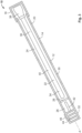
- Reusable urinary catheter products according to the present disclosure and their individual components may be variously configured without departing from the scope of the present disclosure, but in one embodiment, a reusable urinary catheter product 10 is configured as shown in Fig. 1 .
- Figs. 1-3 show a reusable urinary catheter product 10.
- the product 10 includes a storage and sterilization device, such as a case 12.
- the case 12 includes a body 14 and re-closable cap 16.
- the re-closable cap 16 and body 14 may be attached to one another in any manner that allows the cap 16 to be removed and reattached to the body 14 to open and close the opening 18 ( Fig. 2 ) in the distal end 20 of the body 14.
- the re-closable cap 16 may be attached by threads, snap-fit, friction fit, or the like. Referring to Fig. 2 , the cap 16 is removed from the body 14 to open the opening 18 of the case 12 so that the user may access the catheter 22 stored within the case 12.
- the cap 16 also may be tethered to the body 14 by a tether (not shown), so that when the re-closable cap 16 is removed from the body 14 to open the case 12, the cap 16 is tethered to the body 14 to reduce the risk of dropping or losing the cap 16.
- a tether not shown
- the body 14 of the case 12 may be an elongated body that defines a first compartment 24 and a second compartment 26 separated by a barrier 28.
- the body may be generally cylindrical. In other embodiments, the body may have a polygonal cross-sectional shape.
- the first compartment 24 is at least partially defined by a portion 30 of the body 14 that is distal of the barrier 28, and the second compartment 26 is at least partially defined by a portion 32 of the body 14 that is proximal of the barrier 28.
- the second compartment is defined or located at the proximal end portion of the case.
- the plane of the barrier 28 extends generally perpendicular to the longitudinal axis A of the case 1 2/body 14.
- the first compartment 24 is configured to hold the catheter 22, and optionally, a liquid or fluid.
- the catheter 22 includes a proximal insertable end 34 and a distal end 36.
- a drainage member 38 may be associated with the distal end 36 of the catheter 22.
- the catheter 22 may be a hydrophilic catheter that includes a lubricious hydrophilic coating on the catheter shaft 40. When the hydrophilic coating is hydrated, it is activated and becomes lubricious so easing insertion and removal during catheterization.
- the fluid may be a sterilization fluid, a hydration fluid or both.
- the sterilization fluid may be any suitable sterilization fluid, and when the catheter is a hydrophilic catheter, the sterilization fluid also may serve as a hydration medium that hydrates the hydrophilic material of the coating.
- the fluid may include one or more of chlorhexidine, FimH inhibitors, antibacterial materials, nanoparticles with bactericidal effects, oxazolidinones, antibacterial proteins, honey, glucose oxidase, silver, and a surfactant configured to loosen a biofilm from the catheter.
- the second compartment 26 includes a sterilizing light source, such as a UV light source 42.
- the second compartment 26 may also include a power source 44.
- the power source 44 also could, alternatively, be located in a different location from the second compartment 26.
- the UV light source 42 may include one or more light emitting diodes, and the power source 44 may include batteries, which may be rechargeable batteries.
- Sterilizing light, such as UV light, emitted from the light source 42 is directed toward the catheter 22 and is used to sterilize or disinfect the catheter.
- the barrier 28 separating the first and second compartments 24 and 26 allows the passage of sterilizing light, therethrough. Thus, the light travels from the second compartment 26 through the barrier 28 and into the first compartment 24 so that the catheter 22 is exposed to the sterilizing light.
- the barrier 28 may be transparent or translucent.
- the barrier 28 may be made of glass or plastic.
- the case 12 may include reflective material (not shown) that reflects the UV light within the case 12.
- the inner wall of the body 14 and/or cap 16 may be lined with a reflective material.
- the reflective material may be continuous or may be segments of material that are selectively placed on the inner wall of the case 12.
- the case 12 may include a switch 46 to activate the light source 42 to emit sterilizing light.
- the switch 46 may protrude through the outer surface of the case 12 or otherwise be accessible so that it can be operated by the user.
- the switch 46 could be, for example, a push button or knob that is operated by the user's fingers.
- the switch 46 may be associated with the cap 16, such that when the cap 16 is reattached to the body 14, the switch activates the light source 42.
- the switch 46, light source 42, power source 44, and/or a timer may be configured so that the light source 42 emits sterilizing light for a selected period of time, such as a time sufficient to disinfect the catheter 22.
- the catheter may include an outer surface containing titanium oxide.
- the titanium oxide may be integrated with the polymer forming the catheter.
- the titanium oxide may be included in a coating on the surface of the catheter 22.
- the coating may be a hydrophilic coating containing titanium oxide. The combination of the titanium oxide with UV light sterilization can result in faster sterilization times and/or reduced bacterial attachment or colonization on the catheter.
- Fig. 4 illustrates an alternative embodiment of a catheter product 10a having a case 12a for storing and sterilizing a catheter 22a.
- the case 12a includes a body 14a and a cap 16a.
- the body 14a includes a first compartment 24a for holding the catheter 22a, and optionally, a sterilization and/or hydration fluid.
- the body 14a also includes a second compartment 26a containing a sterilizing light source 42a, such as a UV light source, and power source 44a.
- the first and second compartments 24a and 26a are separated by a barrier 28a that allows the passage of sterilizing light therethrough.
- the barrier 28a may be made of the same materials as the barrier 28 described above.
- the first and second compartments 24a and 26a are at least partially defined by the barrier 28a.
- the first compartment 24a is concentric with the second compartment 26a, wherein the first compartment 24a is substantially formed by the barrier 28a.
- the second compartment 26a is defined between the barrier 28a and the wall 29a of the body 14a, wherein the barrier 28a forms an inner wall of the second compartment 26a and the wall 29a of the body 14a forms an outer wall of the compartment 26a.
- the sterilizing light source 42a and power source 44a may be similar to that described above with respect to Figs. 1-3 .
- the light source 42a extends along the wall of the body 14a of the case 12a, and may be coextensive or at least partially coextensive with the catheter shaft.
- the case 12a may include a switch 46a to activate the UV light source.
- the switch 46a may be activated by the user's fingers or may be associated with the closing of the cap 16a.
- the light source 42a, switch 46a, power source 44a and/or timer may be configured such that the light source 42a emits light for a selected period of time.
- the user removes cap 16 from the body 14 to open opening 18 of the case 12.
- the drainage member 38 of the catheter 22 is presented.
- the user removes the catheter 22 from the case 12.
- a sterilization or hydration fluid is present in first compartment 24, optionally, the user removes the fluid from the compartment 24.
- the user may pour the fluid out of the compartment 24 into a sink or toilet.
- the user then performs catheterization.
- the user may rinse the catheter 22, if a clean water supply is available.
- the user places the catheter 22 back into the case 12, and if a sterilization fluid or hydration fluid is being employed, the user may add fluid to the case 12.
- the sterilizing light source 42 is activated to emit sterilizing light, such as UV light.
- the light source 42 may be activated by switch 46 or may be activated by attachment of cap 46. After a select period of time, the light source 42 turns off.
- the catheter product 10 may include a visual or audio indicator indicating to the user that the catheter 22 has been sufficiently sterilized and is ready for reuse.
- the indicator may be, for example, an indicator light.
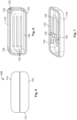
- Figs. 5-7 illustrate another embodiment of a reusable catheter product 110.
- the reusable catheter product includes a case 112.
- the case 112 may include a top portion 114 and a bottom portion 116 that define a re-closable compartment that holds a catheter 118, a sterilizing light source 120 and, optionally, a sterilization and/or hydration fluid (not shown).
- the catheter 118 and the sterilization fluid may be any of those described herein.
- the top and bottom portions 114 and 116 may be configured so as to be completely separated when the compartment is opened.
- the top and bottom portions 114 and 116 may have a clamshell configuration wherein the top and bottom portions are hingedly connected to each other.
- Fig. 6 illustrates the top portion 114 of the case 112
- Fig. 7 illustrates the bottom portion 116 of the case 112.
- the sterilizing light source 120 may be associated with the bottom surface 124 of the top portion 114.
- the sterilizing light source 120 may be located behind a translucent or transparent barrier.
- the light source 120 and power source 122 may be any of the light sources and power sources disclosed herein.
- the power source 122 may include rechargeable batteries and include a port 126 that may be connected to a power cord (not shown) for recharging the batteries.
- the case 112 may also include a switch (not shown) for activating the UV light source.
- the switch may be accessible and activated by the user. Alternatively, the switch may be configured so that the light source 120 is activated upon the closing of the case 112. Additionally, the light source 120, power source 122, switch and/or a timer may be configured so that the light source emits light for a select period of time.
- the case 112 is held in the closed configuration by magnetic material.
- the top portion 114 has a magnetic segment 128 that extends about the periphery or rim 130 of the top portion 114.
- the bottom portion 116 may have a magnetic segment 132 extending about the periphery or rim 134 of the bottom portion 116.
- the magnetic segment 128 of the top portion 114 and the magnetic segment 132 of the bottom portion 116 are aligned, coextensive and/or commensurate when the case 112 is in a closed configuration.
- both the top and bottom portions 114 and 116 include magnetic segments.
- one of the top and bottom portions 114 and 116 includes a magnetic segment and the other of the portions includes a segment attracted to the magnetic material.
- the bottom portion 116 is configured to hold the catheter 118 in a manner that allows the catheter to be removed and reattached to the bottom portion 116.
- the bottom portion 116 includes brackets or mounts 136 for releasably holding the catheter 118.
- the mounts 136 may be U-shaped clips that hold a portion of the catheter 118 by friction or snap fit.
- the mounts 136 hold the catheter in a curved configuration.
- the bottom portion 116 also may include grooves to assist in holding the catheter.
- the catheter is removed from the case for catheterization, and then inserted back into the case for sterilization in a similar process as described above with respect to the embodiment of Figs. 1-3 .
- Figs. 8-12 illustrate another embodiment of a reusable catheter product 210.
- the reusable catheter product includes a sterilizing and storing device 212.
- the device 212 includes a base 214 and a sterilization chamber 216.
- the sterilization chamber 216 may be removably engageable with the base 214. Alternatively, the sterilization chamber 216 may be permanently attached to the base 214.
- the chamber 216 has a generally cylindrical shape that defines an inner cavity. Alternatively, the chamber 216 may have other shapes.
- the chamber 216 also includes an opening 218 in the top end 220 and an opening 222 in the bottom end 224.
- a cradle 226 ( Fig. 10 ) is inserted into and located within the chamber 216 ( Figs. 8 and 12 ).
- the cradle 226 is configured to hold a catheter 228 within the chamber 216.
- the cradle 226 includes a top section 230 that defines a chamber cap 230a which defines the top of the cavity of the chamber 216.
- the chamber cap 230a includes a handle, such as the illustrated ring-shaped member 232, that may be grasped by the user to manipulate the cradle 226.
- the chamber cap 230a may also include a seal 234 for creating a fluid tight seal between the cap 230a and the chamber 216, when the cradle 226 is inserted into the chamber 216.
- the seal may be, for example, an O-ring within a groove 236.
- the cradle 226 also includes a bottom section 238 that is connected to the top section 230.
- the top section 230 and the bottom section 238 are connected by two rods 240 extending between the two sections.
- the top and bottom sections 226 and 238 may be connected in any suitable manner.
- the bottom section 238 when the cradle 226 is inserted into the chamber 216, the bottom section 238 may define the bottom of cavity of the chamber 216. Additionally, the bottom section 238 may form a fluid tight seal with the chamber 216. Furthermore, the bottom section 238 may be axially recessed from the bottom edge 239 of the chamber 216. Referring to Figs. 10 and 12 , the bottom section 238 of the cradle 226 includes a boss 242 extending upward from the top surface 244 of the bottom section 238. The boss 242 is configured to engage the distal end of a drainage member 246 of the catheter 228.
- the boss 242 defines a lumen 248 that extends through the bottom section 238 and allows the passage of flushing fluid therethrough and into the lumen 250 of the drainage member 246.
- the boss 242 includes a cone or truncated cone shape. In other embodiments, the boss 242 may be any suitable shape.
- the base 214 includes a housing 252 that houses a fluid supply 254 and a pump 256.
- the base 214/housing 252 also includes a cavity 258 that accepts the bottom 224 of the chamber 216.
- a mounting member 260 extends upward from the bottom surface 262 defining the cavity 258. Referring to Fig. 12 , when the chamber 216 is inserted into the cavity 258, the mounting member 260 is accepted into the recess defined by the bottom section 238 of the cradle 226 and the bottom of the chamber 216.
- the mounting member 260 includes a lumen 264 that is aligned within and in fluid communication with the lumen 248 of the boss 242 of the bottom section 238 of the cradle 226.
- a fluid flow path 266 extends between the pump 256 and lumen 264 of the mounting member 260 of the cavity 258.
- the pump 256 pumps flushing fluid from the fluid supply 254, through the fluid flow path 266 and lumens 264 and 248 into the lumen 250 of the drainage member 246 of the catheter 228.
- the fluid flow path 226 and lumens 264 and 248 serve as a fluid conduit between the fluid supply 254 and the drainage member 246 of the catheter 228.
- the flushing fluid flows through the catheter shaft 268 and out of the eye 270 in the proximal end of the catheter 228 to disinfect and remove microbials and particles from the inner surface of the lumen of the catheter shaft.
- the flushing fluid may be any of the sterilization and/or hydration fluids disclosed herein.
- the base 214 may also include a tower 272 extending upward from the base.
- the tower When the chamber 216 is engaged with the base 214, the tower also may extend at least partially along the length of the chamber 216.
- the tower 272 includes a sterilizing light source 274.
- the tower 272 may include one or more light emitting diodes that emit sterilizing light, such as UV light.
- the chamber 216 may be made of a glass or plastic that is transparent, translucent or otherwise allows the sterilizing light to pass through the chamber 216 so that the catheter 228 is exposed to such light.
- the user removes the cradle 226 from the chamber 216 and removes the catheter 228 from the cradle. Catheterization is then preformed. Optionally, after catheterization the user rinses the catheter 228 with water. The catheter 228 is then placed back in the cradle 226 with the drainage member 246 engaged with the boss 242. The cradle 226 is then placed back into the chamber 216. If the chamber 216 was removed from the base 214, the chamber 216 is placed into the cavity 258 of the base 214 for receiving the chamber. The pump 256 is then activated to flow flushing fluid from the fluid supply 254 through the fluid flow passageway 266 and lumens 264 and 248 into the lumen 250 of the drainage member 246.
- the flushing fluid flows through the catheter 228 and out of the eyes 270 in the proximal end of the catheter. If a sterilizing light source 274 is included, the light source 274 is activated for a select amount of time to further sterilize the catheter 228 with sterilizing light. After sterilization is completed the catheter is ready for reuse.
- a sterilizing light source 274 is included, the light source 274 is activated for a select amount of time to further sterilize the catheter 228 with sterilizing light. After sterilization is completed the catheter is ready for reuse.
- the light source may be used to refresh or replenish the hydrophilic coating of the catheter.
- Hydrophilic catheter coatings are formed from a hydrophilic polymer.
- the sterilization fluid or hydration medium may contain a hydrophilic polymer in the fluid/medium wherein the hydrophilic polymer is the same polymer as that in the coating or one that is compatible with the hydrophilic polymer of the coating.
- the sterilization fluid or hydration medium comes into contact with the hydrophilic coating of the catheter, some of the hydrophilic polymer from the fluid/medium remains on or becomes entangled with the polymer of the hydrophilic coating.
- Exposure to the sterilizing light source promotes or initiates cross-linking between the hydrophilic polymer of the fluid/medium and the hydrophilic coating of the catheter, thereby refreshing or replenishing the hydrophilic coating with new or additional polymer material.
Landscapes
- Health & Medical Sciences (AREA)
- Life Sciences & Earth Sciences (AREA)
- Animal Behavior & Ethology (AREA)
- Epidemiology (AREA)
- Veterinary Medicine (AREA)
- Public Health (AREA)
- General Health & Medical Sciences (AREA)
- General Chemical & Material Sciences (AREA)
- Chemical Kinetics & Catalysis (AREA)
- Chemical & Material Sciences (AREA)
- Biophysics (AREA)
- Hematology (AREA)
- Heart & Thoracic Surgery (AREA)
- Biomedical Technology (AREA)
- Anesthesiology (AREA)
- Engineering & Computer Science (AREA)
- Pulmonology (AREA)
- Urology & Nephrology (AREA)
- Apparatus For Disinfection Or Sterilisation (AREA)
Claims (15)
- Wiederverwendbares Harnkatheterprodukt (10, 10a), umfassend:ein Gehäuse (12, 12a), das Folgendes umfasst: einen Körper (14, 14a) und eine wiederverschließbare Kappe (16, 16a), wobei der Körper (14, 14a) ein erstes Fach (24, 24a) und ein zweites Fach (26, 26a) definiert, wobei das erste Fach (24, 24a) und das zweite Fach (26, 26a) durch eine Barriere (28, 28a) getrennt sind, die den Durchgang von Sterilisierungslicht ermöglicht;einen Harnkatheter (22, 22a), der sich in dem ersten Fach (24, 24a) befindet; und eine Sterilisierungslichtquelle (42, 42a), die sich in dem zweiten Fach (26) befindet, wobei das von der Lichtquelle (42, 42a) emittierte Sterilisierungslicht durch die Barriere (28, 28a) und in das zweite Fach (26, 26a) hindurchgeht.
- Produkt nach Anspruch 1, wobei der Körper (14) eine längliche Form aufweist und ein benachbartes Ende und ein distales Ende aufweist, wobei sich die Sterilisierungslichtquelle (42) an einem der proximalen und distalen Enden des Körpers (14) befindet.
- Produkt nach Anspruch 2, wobei die Barriere (28) eine Ebene beinhaltet, die senkrecht zu der Längsachse des Körpers (14) verläuft, und das erste Fach (24) durch einen Abschnitt des Körpers (14) definiert ist, der distal zu der Barriere (28) liegt, und das zweite Fach (26) durch einen Abschnitt des Körpers (14) definiert ist, der benachbart zu der Barriere (28) liegt.
- Produkt nach Anspruch 1, wobei das erste Fach und das zweite Fach (24a, 26a) konzentrisch sind.
- Produkt nach einem der vorhergehenden Ansprüche, wobei die Barriere (28, 28a) transparent oder lichtdurchlässig ist.
- Produkt nach einem der vorhergehenden Ansprüche, wobei die Barriere (28, 28a) aus Kunststoff oder Glas besteht.
- Produkt nach einem der vorhergehenden Ansprüche, wobei die Sterilisierungslichtquelle (42, 42) eine oder mehrere lichtemittierende Dioden umfasst.
- Produkt nach einem der vorhergehenden Ansprüche, wobei der Harnkatheter (22, 22a) eine Titanoxidbeschichtung aufweist.
- Produkt nach Anspruch 8, wobei der Harnkatheter (22, 22a) eine gleitfähige hydrophile Beschichtung beinhaltet und die gleitfähige hydrophile Beschichtung das Titanoxid beinhaltet.
- Produkt nach einem der Ansprüche 1-8, wobei der Harnkatheter (22, 22a) eine gleitfähige hydrophile Beschichtung beinhaltet.
- Produkt nach einem der vorhergehenden Ansprüche, das ferner ein Fluid beinhaltet, das sich innerhalb des ersten Fachs (24, 24a) befindet.
- Produkt nach Anspruch 11, wobei das Fluid ein Sterilisierungs- oder Hydratisierungsfluid umfasst.
- Produkt nach Anspruch 12, wobei das Fluid mindestens eines von Folgendem umfasst: ein Antiseptikum, Chlorhexidin, FimH-Inhibitoren, antibakterielle Materialien, Nanopartikel mit bakterizider Wirkung, Oxazolidinone, antibakterielle Proteine, Honig, Glucoseoxidase, Silber und ein Tensid, das dazu konfiguriert ist, einen Biofilm vom Katheter zu lösen.
- Produkt nach einem der vorhergehenden Ansprüche, das ferner eine Stromquelle (44, 44a) zum Versorgen der Sterilisierungslichtquelle (42, 42a) beinhaltet.
- Produkt nach einem der vorhergehenden Ansprüche, wobei das Gehäuse (12, 12a) ferner ein reflektierendes Material beinhaltet, das Sterilisierungslicht reflektiert.
Applications Claiming Priority (2)
| Application Number | Priority Date | Filing Date | Title |
|---|---|---|---|
| US201962905044P | 2019-09-24 | 2019-09-24 | |
| PCT/US2020/052027 WO2021061661A1 (en) | 2019-09-24 | 2020-09-22 | Reusable urinary catheter products |
Related Child Applications (1)
| Application Number | Title | Priority Date | Filing Date |
|---|---|---|---|
| EP24197151.4 Division-Into | 2024-08-29 |
Publications (2)
| Publication Number | Publication Date |
|---|---|
| EP4034178A1 EP4034178A1 (de) | 2022-08-03 |
| EP4034178B1 true EP4034178B1 (de) | 2025-01-15 |
Family
ID=72896065
Family Applications (1)
| Application Number | Title | Priority Date | Filing Date |
|---|---|---|---|
| EP20792782.3A Active EP4034178B1 (de) | 2019-09-24 | 2020-09-22 | Wiederverwendbare harnkatheterprodukte |
Country Status (8)
| Country | Link |
|---|---|
| US (1) | US20220370760A1 (de) |
| EP (1) | EP4034178B1 (de) |
| AU (1) | AU2020352978B2 (de) |
| CA (1) | CA3155499A1 (de) |
| DK (1) | DK4034178T3 (de) |
| HU (1) | HUE070854T2 (de) |
| LT (1) | LT4034178T (de) |
| WO (1) | WO2021061661A1 (de) |
Families Citing this family (3)
| Publication number | Priority date | Publication date | Assignee | Title |
|---|---|---|---|---|
| US11786620B2 (en) | 2018-04-30 | 2023-10-17 | CathBuddy, Inc. | Handheld cleaner-disinfector for medical devices |
| US10639389B2 (en) | 2018-04-30 | 2020-05-05 | CathBuddy, Inc | Methods and devices for portable sterilization and containment of medical devices |
| US11911571B2 (en) | 2020-04-24 | 2024-02-27 | Convatec Limited | Packaging for a medical device |
Citations (1)
| Publication number | Priority date | Publication date | Assignee | Title |
|---|---|---|---|---|
| US9550005B2 (en) * | 2013-10-29 | 2017-01-24 | Ultraviolet Interventions, Inc. | Systems and methods for sterilization using UV light |
Family Cites Families (7)
| Publication number | Priority date | Publication date | Assignee | Title |
|---|---|---|---|---|
| US5310524A (en) * | 1992-02-11 | 1994-05-10 | Minntech Corporation | Catheter reprocessing and sterilizing system |
| US6039928A (en) * | 1998-01-28 | 2000-03-21 | Roberts; Jon L. | Writing implement sterilization apparatus |
| US8946653B2 (en) * | 2013-03-14 | 2015-02-03 | Teleflex Medical Incorporated | UV-C catheter hub sterilization and data acquisition system |
| US10888685B2 (en) * | 2015-03-03 | 2021-01-12 | Tsukada Medical Research Co., Ltd. | Unit for balloon catheter, and indwelling urethral balloon catheter |
| US9603958B2 (en) * | 2015-06-04 | 2017-03-28 | Deborah Mitchell | Sterilization assembly |
| US10639389B2 (en) * | 2018-04-30 | 2020-05-05 | CathBuddy, Inc | Methods and devices for portable sterilization and containment of medical devices |
| US11771785B2 (en) * | 2019-05-10 | 2023-10-03 | Bassiri, Inc. | Untethered disenfecting stethoscope system |
-
2020
- 2020-09-22 DK DK20792782.3T patent/DK4034178T3/da active
- 2020-09-22 HU HUE20792782A patent/HUE070854T2/hu unknown
- 2020-09-22 EP EP20792782.3A patent/EP4034178B1/de active Active
- 2020-09-22 WO PCT/US2020/052027 patent/WO2021061661A1/en not_active Ceased
- 2020-09-22 CA CA3155499A patent/CA3155499A1/en active Pending
- 2020-09-22 AU AU2020352978A patent/AU2020352978B2/en active Active
- 2020-09-22 LT LTEPPCT/US2020/052027T patent/LT4034178T/lt unknown
- 2020-09-22 US US17/761,970 patent/US20220370760A1/en active Pending
Patent Citations (1)
| Publication number | Priority date | Publication date | Assignee | Title |
|---|---|---|---|---|
| US9550005B2 (en) * | 2013-10-29 | 2017-01-24 | Ultraviolet Interventions, Inc. | Systems and methods for sterilization using UV light |
Also Published As
| Publication number | Publication date |
|---|---|
| LT4034178T (lt) | 2025-04-10 |
| CA3155499A1 (en) | 2021-04-01 |
| DK4034178T3 (da) | 2025-03-24 |
| HUE070854T2 (hu) | 2025-07-28 |
| WO2021061661A1 (en) | 2021-04-01 |
| EP4034178A1 (de) | 2022-08-03 |
| AU2020352978A1 (en) | 2022-04-14 |
| AU2020352978B2 (en) | 2025-09-04 |
| US20220370760A1 (en) | 2022-11-24 |
Similar Documents
| Publication | Publication Date | Title |
|---|---|---|
| EP4034178B1 (de) | Wiederverwendbare harnkatheterprodukte | |
| JP6559955B2 (ja) | ポートおよび表面清浄装置および技法 | |
| US10076653B2 (en) | Medical caps and methods of use | |
| EP3952929B1 (de) | Wiederverwendbare harnkatheterprodukte | |
| JP2015507954A (ja) | 結合されたキャップアプリケータ | |
| EP2161040A1 (de) | Vorrichtung zum Sterilisieren von Rohrlumen | |
| AU2020291419B2 (en) | Reusable urinary catheter kits | |
| CN103874514B (zh) | 隐形眼镜清洁系统 | |
| WO2005016100A1 (en) | Toothbrush holder | |
| CN106948658B (zh) | 一种消毒把手 | |
| US20250152763A1 (en) | Intermittent catheter storage/sterilisation | |
| CN109172005B (zh) | 一种新型术前消毒浸泡装置 | |
| KR20220107692A (ko) | 소독캡슐 및 소독장치 |
Legal Events
| Date | Code | Title | Description |
|---|---|---|---|
| STAA | Information on the status of an ep patent application or granted ep patent |
Free format text: STATUS: UNKNOWN |
|
| STAA | Information on the status of an ep patent application or granted ep patent |
Free format text: STATUS: THE INTERNATIONAL PUBLICATION HAS BEEN MADE |
|
| PUAI | Public reference made under article 153(3) epc to a published international application that has entered the european phase |
Free format text: ORIGINAL CODE: 0009012 |
|
| STAA | Information on the status of an ep patent application or granted ep patent |
Free format text: STATUS: REQUEST FOR EXAMINATION WAS MADE |
|
| 17P | Request for examination filed |
Effective date: 20220324 |
|
| AK | Designated contracting states |
Kind code of ref document: A1 Designated state(s): AL AT BE BG CH CY CZ DE DK EE ES FI FR GB GR HR HU IE IS IT LI LT LU LV MC MK MT NL NO PL PT RO RS SE SI SK SM TR |
|
| DAV | Request for validation of the european patent (deleted) | ||
| DAX | Request for extension of the european patent (deleted) | ||
| P01 | Opt-out of the competence of the unified patent court (upc) registered |
Effective date: 20230520 |
|
| GRAP | Despatch of communication of intention to grant a patent |
Free format text: ORIGINAL CODE: EPIDOSNIGR1 |
|
| STAA | Information on the status of an ep patent application or granted ep patent |
Free format text: STATUS: GRANT OF PATENT IS INTENDED |
|
| INTG | Intention to grant announced |
Effective date: 20240425 |
|
| GRAS | Grant fee paid |
Free format text: ORIGINAL CODE: EPIDOSNIGR3 |
|
| GRAJ | Information related to disapproval of communication of intention to grant by the applicant or resumption of examination proceedings by the epo deleted |
Free format text: ORIGINAL CODE: EPIDOSDIGR1 |
|
| GRAL | Information related to payment of fee for publishing/printing deleted |
Free format text: ORIGINAL CODE: EPIDOSDIGR3 |
|
| GRAS | Grant fee paid |
Free format text: ORIGINAL CODE: EPIDOSNIGR3 |
|
| STAA | Information on the status of an ep patent application or granted ep patent |
Free format text: STATUS: REQUEST FOR EXAMINATION WAS MADE |
|
| GRAP | Despatch of communication of intention to grant a patent |
Free format text: ORIGINAL CODE: EPIDOSNIGR1 |
|
| STAA | Information on the status of an ep patent application or granted ep patent |
Free format text: STATUS: GRANT OF PATENT IS INTENDED |
|
| INTC | Intention to grant announced (deleted) | ||
| INTG | Intention to grant announced |
Effective date: 20241007 |
|
| GRAS | Grant fee paid |
Free format text: ORIGINAL CODE: EPIDOSNIGR3 |
|
| GRAA | (expected) grant |
Free format text: ORIGINAL CODE: 0009210 |
|
| STAA | Information on the status of an ep patent application or granted ep patent |
Free format text: STATUS: THE PATENT HAS BEEN GRANTED |
|
| AK | Designated contracting states |
Kind code of ref document: B1 Designated state(s): AL AT BE BG CH CY CZ DE DK EE ES FI FR GB GR HR HU IE IS IT LI LT LU LV MC MK MT NL NO PL PT RO RS SE SI SK SM TR |
|
| REG | Reference to a national code |
Ref country code: CH Ref legal event code: EP Ref country code: GB Ref legal event code: FG4D |
|
| REG | Reference to a national code |
Ref country code: DE Ref legal event code: R096 Ref document number: 602020044880 Country of ref document: DE |
|
| REG | Reference to a national code |
Ref country code: IE Ref legal event code: FG4D |
|
| REG | Reference to a national code |
Ref country code: DK Ref legal event code: T3 Effective date: 20250319 |
|
| REG | Reference to a national code |
Ref country code: NL Ref legal event code: FP |
|
| PG25 | Lapsed in a contracting state [announced via postgrant information from national office to epo] |
Ref country code: RS Free format text: LAPSE BECAUSE OF FAILURE TO SUBMIT A TRANSLATION OF THE DESCRIPTION OR TO PAY THE FEE WITHIN THE PRESCRIBED TIME-LIMIT Effective date: 20250415 |
|
| PG25 | Lapsed in a contracting state [announced via postgrant information from national office to epo] |
Ref country code: FI Free format text: LAPSE BECAUSE OF FAILURE TO SUBMIT A TRANSLATION OF THE DESCRIPTION OR TO PAY THE FEE WITHIN THE PRESCRIBED TIME-LIMIT Effective date: 20250115 |
|
| PG25 | Lapsed in a contracting state [announced via postgrant information from national office to epo] |
Ref country code: PL Free format text: LAPSE BECAUSE OF FAILURE TO SUBMIT A TRANSLATION OF THE DESCRIPTION OR TO PAY THE FEE WITHIN THE PRESCRIBED TIME-LIMIT Effective date: 20250115 |
|
| PG25 | Lapsed in a contracting state [announced via postgrant information from national office to epo] |
Ref country code: ES Free format text: LAPSE BECAUSE OF FAILURE TO SUBMIT A TRANSLATION OF THE DESCRIPTION OR TO PAY THE FEE WITHIN THE PRESCRIBED TIME-LIMIT Effective date: 20250115 |
|
| PG25 | Lapsed in a contracting state [announced via postgrant information from national office to epo] |
Ref country code: IS Free format text: LAPSE BECAUSE OF FAILURE TO SUBMIT A TRANSLATION OF THE DESCRIPTION OR TO PAY THE FEE WITHIN THE PRESCRIBED TIME-LIMIT Effective date: 20250515 Ref country code: NO Free format text: LAPSE BECAUSE OF FAILURE TO SUBMIT A TRANSLATION OF THE DESCRIPTION OR TO PAY THE FEE WITHIN THE PRESCRIBED TIME-LIMIT Effective date: 20250415 |
|
| REG | Reference to a national code |
Ref country code: AT Ref legal event code: MK05 Ref document number: 1759426 Country of ref document: AT Kind code of ref document: T Effective date: 20250115 |
|
| PG25 | Lapsed in a contracting state [announced via postgrant information from national office to epo] |
Ref country code: HR Free format text: LAPSE BECAUSE OF FAILURE TO SUBMIT A TRANSLATION OF THE DESCRIPTION OR TO PAY THE FEE WITHIN THE PRESCRIBED TIME-LIMIT Effective date: 20250115 |
|
| PG25 | Lapsed in a contracting state [announced via postgrant information from national office to epo] |
Ref country code: LV Free format text: LAPSE BECAUSE OF FAILURE TO SUBMIT A TRANSLATION OF THE DESCRIPTION OR TO PAY THE FEE WITHIN THE PRESCRIBED TIME-LIMIT Effective date: 20250115 Ref country code: PT Free format text: LAPSE BECAUSE OF FAILURE TO SUBMIT A TRANSLATION OF THE DESCRIPTION OR TO PAY THE FEE WITHIN THE PRESCRIBED TIME-LIMIT Effective date: 20250515 |
|
| PG25 | Lapsed in a contracting state [announced via postgrant information from national office to epo] |
Ref country code: BG Free format text: LAPSE BECAUSE OF FAILURE TO SUBMIT A TRANSLATION OF THE DESCRIPTION OR TO PAY THE FEE WITHIN THE PRESCRIBED TIME-LIMIT Effective date: 20250115 Ref country code: GR Free format text: LAPSE BECAUSE OF FAILURE TO SUBMIT A TRANSLATION OF THE DESCRIPTION OR TO PAY THE FEE WITHIN THE PRESCRIBED TIME-LIMIT Effective date: 20250416 |
|
| PG25 | Lapsed in a contracting state [announced via postgrant information from national office to epo] |
Ref country code: AT Free format text: LAPSE BECAUSE OF FAILURE TO SUBMIT A TRANSLATION OF THE DESCRIPTION OR TO PAY THE FEE WITHIN THE PRESCRIBED TIME-LIMIT Effective date: 20250115 |
|
| REG | Reference to a national code |
Ref country code: HU Ref legal event code: AG4A Ref document number: E070854 Country of ref document: HU |
|
| PG25 | Lapsed in a contracting state [announced via postgrant information from national office to epo] |
Ref country code: SE Free format text: LAPSE BECAUSE OF FAILURE TO SUBMIT A TRANSLATION OF THE DESCRIPTION OR TO PAY THE FEE WITHIN THE PRESCRIBED TIME-LIMIT Effective date: 20250115 |
|
| PG25 | Lapsed in a contracting state [announced via postgrant information from national office to epo] |
Ref country code: SM Free format text: LAPSE BECAUSE OF FAILURE TO SUBMIT A TRANSLATION OF THE DESCRIPTION OR TO PAY THE FEE WITHIN THE PRESCRIBED TIME-LIMIT Effective date: 20250115 |
|
| PGFP | Annual fee paid to national office [announced via postgrant information from national office to epo] |
Ref country code: DE Payment date: 20250929 Year of fee payment: 6 Ref country code: LT Payment date: 20250903 Year of fee payment: 6 Ref country code: DK Payment date: 20250925 Year of fee payment: 6 |
|
| PG25 | Lapsed in a contracting state [announced via postgrant information from national office to epo] |
Ref country code: IT Free format text: LAPSE BECAUSE OF FAILURE TO SUBMIT A TRANSLATION OF THE DESCRIPTION OR TO PAY THE FEE WITHIN THE PRESCRIBED TIME-LIMIT Effective date: 20250115 |
|
| PGFP | Annual fee paid to national office [announced via postgrant information from national office to epo] |
Ref country code: NL Payment date: 20250926 Year of fee payment: 6 |
|
| PGFP | Annual fee paid to national office [announced via postgrant information from national office to epo] |
Ref country code: HU Payment date: 20250910 Year of fee payment: 6 Ref country code: GB Payment date: 20250929 Year of fee payment: 6 |
|
| REG | Reference to a national code |
Ref country code: DE Ref legal event code: R097 Ref document number: 602020044880 Country of ref document: DE |
|
| PGFP | Annual fee paid to national office [announced via postgrant information from national office to epo] |
Ref country code: FR Payment date: 20250925 Year of fee payment: 6 |
|
| PG25 | Lapsed in a contracting state [announced via postgrant information from national office to epo] |
Ref country code: CZ Free format text: LAPSE BECAUSE OF FAILURE TO SUBMIT A TRANSLATION OF THE DESCRIPTION OR TO PAY THE FEE WITHIN THE PRESCRIBED TIME-LIMIT Effective date: 20250115 Ref country code: EE Free format text: LAPSE BECAUSE OF FAILURE TO SUBMIT A TRANSLATION OF THE DESCRIPTION OR TO PAY THE FEE WITHIN THE PRESCRIBED TIME-LIMIT Effective date: 20250115 |
|
| PGFP | Annual fee paid to national office [announced via postgrant information from national office to epo] |
Ref country code: IE Payment date: 20250929 Year of fee payment: 6 |
|
| PG25 | Lapsed in a contracting state [announced via postgrant information from national office to epo] |
Ref country code: RO Free format text: LAPSE BECAUSE OF FAILURE TO SUBMIT A TRANSLATION OF THE DESCRIPTION OR TO PAY THE FEE WITHIN THE PRESCRIBED TIME-LIMIT Effective date: 20250115 |
|
| PG25 | Lapsed in a contracting state [announced via postgrant information from national office to epo] |
Ref country code: SK Free format text: LAPSE BECAUSE OF FAILURE TO SUBMIT A TRANSLATION OF THE DESCRIPTION OR TO PAY THE FEE WITHIN THE PRESCRIBED TIME-LIMIT Effective date: 20250115 |
|
| PLBE | No opposition filed within time limit |
Free format text: ORIGINAL CODE: 0009261 |
|
| STAA | Information on the status of an ep patent application or granted ep patent |
Free format text: STATUS: NO OPPOSITION FILED WITHIN TIME LIMIT |
|
| 26N | No opposition filed |
Effective date: 20251016 |