EP4034064B1 - Locking arrangement for patient lift - Google Patents
Locking arrangement for patient lift Download PDFInfo
- Publication number
- EP4034064B1 EP4034064B1 EP20772259.6A EP20772259A EP4034064B1 EP 4034064 B1 EP4034064 B1 EP 4034064B1 EP 20772259 A EP20772259 A EP 20772259A EP 4034064 B1 EP4034064 B1 EP 4034064B1
- Authority
- EP
- European Patent Office
- Prior art keywords
- shape memory
- locking
- memory alloy
- alloy element
- configuration
- Prior art date
- Legal status (The legal status is an assumption and is not a legal conclusion. Google has not performed a legal analysis and makes no representation as to the accuracy of the status listed.)
- Active
Links
Images




Classifications
-
- A—HUMAN NECESSITIES
- A61—MEDICAL OR VETERINARY SCIENCE; HYGIENE
- A61G—TRANSPORT, PERSONAL CONVEYANCES, OR ACCOMMODATION SPECIALLY ADAPTED FOR PATIENTS OR DISABLED PERSONS; OPERATING TABLES OR CHAIRS; CHAIRS FOR DENTISTRY; FUNERAL DEVICES
- A61G7/00—Beds specially adapted for nursing; Devices for lifting patients or disabled persons
- A61G7/10—Devices for lifting patients or disabled persons, e.g. special adaptations of hoists thereto
- A61G7/1013—Lifting of patients by
- A61G7/1015—Cables, chains or cords
-
- A—HUMAN NECESSITIES
- A61—MEDICAL OR VETERINARY SCIENCE; HYGIENE
- A61G—TRANSPORT, PERSONAL CONVEYANCES, OR ACCOMMODATION SPECIALLY ADAPTED FOR PATIENTS OR DISABLED PERSONS; OPERATING TABLES OR CHAIRS; CHAIRS FOR DENTISTRY; FUNERAL DEVICES
- A61G7/00—Beds specially adapted for nursing; Devices for lifting patients or disabled persons
- A61G7/10—Devices for lifting patients or disabled persons, e.g. special adaptations of hoists thereto
- A61G7/104—Devices carried or supported by
- A61G7/1042—Rail systems
-
- A—HUMAN NECESSITIES
- A61—MEDICAL OR VETERINARY SCIENCE; HYGIENE
- A61G—TRANSPORT, PERSONAL CONVEYANCES, OR ACCOMMODATION SPECIALLY ADAPTED FOR PATIENTS OR DISABLED PERSONS; OPERATING TABLES OR CHAIRS; CHAIRS FOR DENTISTRY; FUNERAL DEVICES
- A61G7/00—Beds specially adapted for nursing; Devices for lifting patients or disabled persons
- A61G7/10—Devices for lifting patients or disabled persons, e.g. special adaptations of hoists thereto
- A61G7/1063—Safety means
-
- F—MECHANICAL ENGINEERING; LIGHTING; HEATING; WEAPONS; BLASTING
- F16—ENGINEERING ELEMENTS AND UNITS; GENERAL MEASURES FOR PRODUCING AND MAINTAINING EFFECTIVE FUNCTIONING OF MACHINES OR INSTALLATIONS; THERMAL INSULATION IN GENERAL
- F16D—COUPLINGS FOR TRANSMITTING ROTATION; CLUTCHES; BRAKES
- F16D63/00—Brakes not otherwise provided for; Brakes combining more than one of the types of groups F16D49/00 - F16D61/00
- F16D63/006—Positive locking brakes
-
- F—MECHANICAL ENGINEERING; LIGHTING; HEATING; WEAPONS; BLASTING
- F16—ENGINEERING ELEMENTS AND UNITS; GENERAL MEASURES FOR PRODUCING AND MAINTAINING EFFECTIVE FUNCTIONING OF MACHINES OR INSTALLATIONS; THERMAL INSULATION IN GENERAL
- F16D—COUPLINGS FOR TRANSMITTING ROTATION; CLUTCHES; BRAKES
- F16D2121/00—Type of actuator operation force
- F16D2121/18—Electric or magnetic
- F16D2121/32—Electric or magnetic using shape memory or other thermo-mechanical elements
-
- F—MECHANICAL ENGINEERING; LIGHTING; HEATING; WEAPONS; BLASTING
- F16—ENGINEERING ELEMENTS AND UNITS; GENERAL MEASURES FOR PRODUCING AND MAINTAINING EFFECTIVE FUNCTIONING OF MACHINES OR INSTALLATIONS; THERMAL INSULATION IN GENERAL
- F16D—COUPLINGS FOR TRANSMITTING ROTATION; CLUTCHES; BRAKES
- F16D2127/00—Auxiliary mechanisms
- F16D2127/001—Auxiliary mechanisms for automatic or self-acting brake operation
-
- F—MECHANICAL ENGINEERING; LIGHTING; HEATING; WEAPONS; BLASTING
- F16—ENGINEERING ELEMENTS AND UNITS; GENERAL MEASURES FOR PRODUCING AND MAINTAINING EFFECTIVE FUNCTIONING OF MACHINES OR INSTALLATIONS; THERMAL INSULATION IN GENERAL
- F16D—COUPLINGS FOR TRANSMITTING ROTATION; CLUTCHES; BRAKES
- F16D2127/00—Auxiliary mechanisms
- F16D2127/06—Locking mechanisms, e.g. acting on actuators, on release mechanisms or on force transmission mechanisms
Definitions
- the present invention relates to a locking arrangement for a patient lift.
- the present invention further relates to a patient lift comprising such a locking arrangement.
- Patient lifts also referred to as patient hoists
- Patient lifts are commonly used to raise, lower and transfer patients who are disabled or who otherwise have mobility problems.
- Two common types of patient lifts are stanchion-mounted lifts, also known as floor lifts. and ceiling lifts.
- Floor lifts often have a hoist assembly which may be disposed at the upper end of a stanchion.
- the stanchion has a wheeled base, which allows for the lift to be moved along the ground to different locations.
- a lifting member which may be in the form of a spreader bar, such as a two-point attachment spreader bar, a three-point attachment spreader bar, a four-point attachment spreader bar, a five-point attachment spreader bar or a powered spreader bar for adjusting the angle of the spreader bar, for supporting a patient harness or sling descends from the hoist assembly on a strap or a cable.
- the strap or cable is wound around a motorized drum for raising and lowering the patient harness or sling.
- Transmissions are in most cases in the form of parallel transmissions in the form of standard gears and strap, pulley and planetary gears or worm gear stages.
- the toughest challenge for such transmissions is to allow for a locking functionality.
- the locking allows for the transmission to maintain a load at a fixed position even when the lift is in a powerless state.
- Parallel transmissions are in themselves not locking but allows for high efficiency.
- a mechanical brake is required to allow for the locking functionality.
- the mechanical brake may be applied directly on the motor shaft to reduce the required braking torque to a minimum.
- Such a mechanical brake may comprise a solenoid and a braking pad. The solenoid is often expensive and requires a lot of power to operate.
- Worm gear transmissions are often less efficient but allows for locking up to a certain load, often around 110 to 120 Kg.
- the motor has to be provided with power to give a small amount of torque to maintain the load suspended in the lift at the same height.
- an electrical brake may be utilized.
- these electrical brakes are expensive and difficult to disengage in case of an emergency.
- a locking arrangement for a patient lift is provided.
- the locking arrangement is configured to selectively lock the vertical movement of a patient support mounting device connected to a lifting device of the patient lift via a load bearing member.
- the locking arrangement is configured to operate in an engaged mode and a disengaged mode.
- the shape memory alloy element In the engaged mode the shape memory alloy element is in a first configuration and the locking device is in an engaged position in relation to the engagement member for exerting a locking force on the engagement member thereby preventing vertical movement of the patient support mounting device.
- the shape memory alloy element In the disengaged mode the shape memory alloy element is in a second configuration actuating the locking device to a disengaged position in relation to the engagement member thereby enabling vertical movement of the patient support mounting device.
- a patient lift comprising a lifting device, a patient support mounting device and a load bearing member.
- the patient support mounting device is connected to the lifting device via the load bearing member.
- the patient lift comprises a locking arrangement according to the above.
- the patient support mounting device 11 may comprise attachment elements 19 for attaching the patient support 15 to the patient support mounting device 11.
- the attachment elements may comprise hooks with latches.
- the locking arrangement is configured to operate in an engaged mode and a disengaged mode.
- the shape memory alloy element 151, 251 is in a first configuration and the locking device 155, 250 is in an engaged position for exerting a locking force on the engagement member 173, 273 thereby preventing vertical movement of the patient support mounting device 11.
- a shape-memory alloy is as is known in the prior art an alloy which can be deformed in a cold state but returns to a pre-deformed shape when heated.
- Shape-memory alloys are also known in the prior art as memory metals, memory alloys, smart metals, smart alloys or muscle wires.
- the shape memory alloy element 151, 251 is arranged to actuate the locking device 155, 250 to the disengaged position in relation the engagement member 173, 273 by being in the second configuration when the locking arrangement operates in the disengaged mode.
- the shape memory alloy element 151, 251 thus actuates the locking device 155, 250 away from the engaged position against the locking force exerted by the biasing of the locking device 155, 250.
- biased locking device provides for a more reliant and robust locking functionality.
- the shape memory alloy element 151, 251 is a muscle wire.
- the shape memory alloy element 151, 251 may be arranged to be electrically connected to at least one power source for selectively transitioning between the first and second configuration.
- the locking arrangement 100, 200 is further arranged to switch from the engaged mode to the disengaged mode by means of the shape memory alloy element 151, 251 transitioning from the first configuration to the second configuration in response to receiving a current provided by said power source exceeding a first configuration threshold current.
- the current is provided by a single power source. In one embodiment, the current is provided by a plurality of power sources.
- Each of the first and second configuration may be associated with a temperature interval.
- the first configuration is associated with a first temperature interval
- the second configuration is associated with a second temperature interval.
- the first configuration temperature interval defines a temperature interval substantially lower than the second configuration temperature interval.
- the first configuration threshold current is thus associated with a temperature of the shape memory alloy element 151, 251 within the second configuration temperature interval, causing the transition from the first configuration to the second configuration.
- the second threshold current is thus associated with the first configuration temperature interval. Accordingly, the second threshold currents result in the temperature of the smart metal alloy element 151, 251 cooling down, allowing for the transition from the second configuration to the first configuration.
- the power source may be electrically connected to the motor 170, 270 for driving said motor 170, 270.
- the first configuration threshold current may be associated with an operating current range of the motor 170, 270.
- a plurality of power sources may be electrically connected to the motor for driving said motor.
- the locking arrangement is arranged to switch from the disengaged mode to the engaged mode in response to no power being provided to the motor 170, 270.
- the locking arrangement may thus function as an emergency brake which is actuated in response to the patient lift not being supplied with power. As soon as power is supplied to the motor 170, 270 the locking arrangement switches from the engaged mode to the disengaged mode, which allows for normal operation of the patient lift.
- Figure 2 depicts the locking arrangement mounted in the patient lifting device 113.
- the motor 170 of the patient lift is connected to the load bearing member 12 via the transmission 128.
- the lifting device 113 is mountable to the rail 114 by means of set wheels 199.
- Figure 3 depicts a cross-section view of the self-locking arrangement.
- the locking arrangement comprises a casing 159.
- the casing 159 is arranged to receive the engagement member 173.
- the engagement member 173 is a friction disc fixated to the output shaft 174.
- the locking device 155 may be arranged to be in braking contact with the engagement member 173 while the locking arrangement 100 operates in the engaged mode.
- the locking device 155 in the engaged position may form a tangent to said engagement member 173 and in the disengaged position is arranged to be in an offset angle to said engagement member 173.
- the shape metal alloy element 151 is arranged to allow for the locking device 155 to be in its engaged position, wherein the locking device 155 comes into braking contact with the engagement member 173 when the locking arrangement operates in the engaged mode.
- the shape metal alloy element 151 may thus be arranged to expand to allow for the locking device 155 to come into braking contact with the engagement member 173 in response to receiving a current subceeding the second threshold current.
- the locking device 155 maybe biased.
- the locking device 155 is in a resilient material. Said resilient material is biased to exert the locking force onto the engagement member 173 and actuating the locking device 155 to the engaged position when the locking arrangement operates in the engaged mode and the shape memory alloy element 151 is in the first configuration.
- the resilient material thus causes the locking device 155 to come into braking contact with the engagement member 173 while the shape memory alloy element 151 is in the first configuration.
- the resilient material causes the locking device 155 to come into braking contact with the engagement member 173 when the shape memory alloy element 151 transitions from the second to the first configuration, i.e. expands.
- the contraction of said shape memory alloy element 151 causes the locking device 155 to be moved out of braking contact with the engagement member 173. Thereby said transition counteracts the biasing force provided by resilient material of the locking device 155.
- the locking device 155 may comprise a friction pad arranged to come into braking contact with the engagement member 173.
- a first end portion 156 of the locking device 155 is attached to an inner surface of the casing 159.
- a second end portion, i.e. an opposite end portion, of the locking device 155 is attached to the shape memory alloy element 151.
- the locking device 155 is arranged to move between the engaged position and the disengaged position in an angle relative a tangent of the engagement member 173.
- the locking device 155 In the engaged position the locking device 155 is arranged to form a tangent to the engagement member coming into braking contact with said engagement member 173. Accordingly, the angle in relation to said tangent may be zero.
- the locking device 155 In the disengaged position, the locking device 155 is inclined relative said tangent to the engagement member 173 to not be in braking contact with said engagement member 173.
- first end portion 156 may be attached to the inner surface of the casing 159 by means of fastening element(s) 161.
- the intermediate portion 154 may be a bent portion of the shape memory alloy element 151 for example in the form a loop-shaped portion.
- the bent portion is arranged to extend inwardly towards the engagement member 173.
- the inward end of the bent portion 154 may be attached to the locking device 155.
- the end portion may be attached to the second end portion 157.
- the suspension arrangement 180 may comprise a first and second port 153 for electrically connecting the shape memory alloy element 151 to the power source.
- the ports may be connected to the power source via a first and second cable 194, 195.
- the casing 159 may be arranged to receive the motor 170 therein.
- the motor 170 of the patient lift may be mounted inside the casing of the self-locking arrangement.
- the motor 170 and the locking arrangement may thus constitute a single motor unit which includes the locking functionality. This enables a more efficient and less complex retro-fitting of the locking arrangement to existing patient lifts.
- the engagement member 173 may be directly mounted to the output shaft 174.
- the engagement member 173 may be in the form of a friction wheel or disc.
- the friction wheel may be fixed to the output shaft 174.
- the friction disc may be coaxial with the output shaft 174.
- the suspension arrangement may comprise a guiding channel 185 for receiving the intermediate portion 154.
- the guiding channel may extend along the suspension arrangement 180.
- a portion of said guiding channel 185 extends inwardly towards the locking device 155.
- the shape metal alloy element 151 extends along the walls of the guiding channel 185 inwards through the inwardly extending portion through an aperture allowing passage for said shape metal alloy element 151 towards the locking device 155.
- the intermediate portion 154 of the shape metal alloy element 151 extends along opposite guiding surfaces of said guiding channel 185, the intermediate portion being in contact with said guiding surfaces.
- the casing may comprise a through-hole for allowing passage of the intermediate portion 154.
- the suspension arrangement 180 may arc shaped and arranged to be mounted to the outer cylindrical surface of the casing 159.
- Figure 9-12 depicts aspects of another embodiment of the locking arrangement.
- the locking arrangement 200 is arranged to mechanically connect the motor 270 and a transmission unit 228 of the patient lift 213.
- the locking arrangement may be arranged to transfer torque between the motor 270 and the transmission unit 228.
- the transmission unit 228 is arranged to transfer torque from the motor 270 to the load bearing member of the patient lift.
- the locking arrangement 200 is arranged to selectively transfer torque between said motor 270 and transmission unit 228.
- the locking arrangement In the engaged mode, the locking arrangement is arranged to disable torque transfer between the motor 270 and the transmission unit 228.
- the locking arrangement In the disengaged mode, the locking arrangement is arranged to enable torque transfer between the motor 270 and the transmission unit 228.
- the patient lift may thus comprise the motor 270 and transmission unit 228. Said motor and transmission unit may be comprised in the lifting device.
- the locking device 250 may be arranged to move between the engaged position and the disengaged position in a direction substantially parallel to the output shaft 274. Accordingly, the shape memory alloy element 251 is arranged to move the locking device 250 between the engaged position and the disengaged position in said direction substantially parallel to the output shaft 274. In response to receiving a current exceeding the first threshold current, the shape memory alloy element 251 is arranged to contract to the second configuration causing the locking device 250 to move to the disengaged position in the direction substantially parallel to the output shaft 274. In response to receiving a current subceeding the second threshold current, the shape memory alloy element 251 is arranged to expand to the first configuration causing the locking device to move to the engaged position in the direction the direction substantially parallel to the output shaft 274.
- the shape memory alloy element 251 may thus be arranged parallel to the output shaft 274. In other words, the shape memory alloy element 251 may be arranged in a direction parallel to the output shaft 274. Hence, the shape memory alloy element 251 may be further arranged to contact in a direction parallel to the output shaft 274.
- the transmission unit 228 may be a worm gear transmission.
- the output shaft 274 may be connected to a worm gear shaft 227.
- the output shaft may be interfacing with a worm gear wheel 229.
- the worm gear wheel may be connected to a drum or winch for raising and lowering the patient support mounting device.
- the load bearing member which may be a flexible member, may be wrapped around said drum or winch.
- a first portion 253 of the shape memory alloy element 251 may be attached to the locking device 250.
- a second portion 252 of the shape memory alloy element 251 is fixed.
- said first portion 253 may be attached to an actuated part 255 of the locking device 250 for moving said locking device 250.
- said second portion 252 may be arranged to be fixated to the motor 270, i.e. an encasing of the motor 270.
- the locking arrangement may comprise a plurality of shape memory alloy elements 251.
- the shape memory alloy elements 251 may extend parallel to each other and to the output shaft.
- Each shape memory alloy element may be arranged to be electrically connected to the power source.
- the shape memory alloy element 251 is in the form of a muscle wire.
- the first portion 253 of the muscle wire may be connected to the locking device 250, i.e. the actuated part 255 of the locking device 250, by means of being at least partially wrapped around one or more protrusions 287 of the locking device 250, i.e. the actuated part 255.
- the wrapping of the shape memory alloy element 251 may allow for a more robust connection between the shape metal alloy element and the locking device, capable of carrying a higher load. Thus, a safer and more reliable locking arrangement may be achieved.
- a first and second end of the shape memory alloy element 251 may be fixed, i.e. comprised in the second portion of the shape memory alloy element 251.
- the first and second end may be arranged to be electrically connected to the power source.
- the first and second end are fix, preferably said first and second end are arranged to be fixated to the motor 270, i.e. the encasing of the motor.
- the locking arrangement may comprise a suspension console 280.
- the second portion 252 of the shape memory alloy element 251 is attached to the suspension console.
- the suspension console may comprise one or more passages arranged to receive the shape memory alloy element 251. Said passages are arranged to extend substantially parallel to the output shaft 274.
- the suspension console 280 may comprise ports for receiving the first and second end of the shape memory alloy element 251 and electrically connect the first and second end of the shape memory alloy element 251 to the power source.
- the suspension console may be mounted to the motor 270.
- the locking arrangement 200 may further comprise a housing 289 for receiving the output shaft 274 and the engagement member 273.
- the locking arrangement 200 may further comprise at least one friction member 275.
- the at least one friction member 275 may be arranged in said housing 289. Said friction member 275 may be arranged to be in the proximity of the engagement member 273. Accordingly, the locking device 250 in the engaged position may be arranged to cause the at least one friction member 275 and the engagement member 273 to come into contact thereby providing a braking torque to the output shaft 274.
- the locking device 250 may thus be arranged to in the engaged position push the engagement member 273 towards the friction member 275 and thereby provide the braking torque to the output shaft 274.
- the locking device 250 may be provided with a friction material and arranged to directly coming into contact with the engagement member 273 in the engaged position and thereby provide braking torque to the output shaft.
- the friction member 275 may be movably arranged in the casing.
- the friction member 275 may be arranged in a recess of the housing, said recess enabling movement of the friction member 275 substantially parallel to the direction of the output shaft 274.
- the locking device may be biased by means of further comprising a biasing part 256.
- the biasing part 256 is spring loaded for exerting a locking force onto the engagement member 273.
- the biasing part 256 is arranged to engage the actuated part 255 for actuating the locking device 250 to the engaged position when the locking arrangement operates in the engaged mode.
- biasing part 256 may be arranged to engage the actuated part 255 upon the locking device moving from the engaged position towards the disengaged position.
- the biasing part 256 may comprise at least one abutment heel 269 arranged to latch onto the actuated part 255.
- the abutment heel 269 may provide a latching surface abutting to the actuated part 255.
- the output shaft 274 may extend distally, whereby the first end of the shape metal alloy 251 may be a distal end of said shape metal alloy element 251.
- the latching surface of the abutment heel 269 may be a distal surface of the biasing part 256. Said latching surface is in abutment with a proximal surface of the actuated part 255, whereby the actuated part is arranged to push the biasing part away, i.e. in a proximal direction, from the engagement member by the proximal surface of the actuated part255 pushing the distal surface 256 of the biasing part 256.
- the biasing part reaches its locking position, i.e. the biasing part locks the engagement member 274.
- the expansion of the shape memory alloy element 251 causes the biasing part to push the locking device 250 to its engaged position, whereby the locking force is provided.
- biasing part 256 may be directly connected to the actuated part 255.
- the biasing part 256 may be attached to the actuated 255 for example by means of fastening elements such as screws.
- biasing part may comprise a pair of abutment heels.
- a first abutment heel may extend outwardly in a first direction, whereby a second abutment heel may extend outwardly in a second direction opposite to the first direction.
- the housing 289 may comprise one or more locking device tracks 298 for supporting the locking device 250 along its movement between the engaged position and the disengaged position.
- the guided movement of the locking device provided by the locking device tracks allows for a more exact and reliable locking.
- Preferably said locking device tracks may be arranged to support the actuated part 255 of the locking device 250.
- the locking device tracks 298 may be arranged to extend substantially parallel to the output shaft 274.
- the actuated part 255 is substantially U-shaped, whereby the housing 289 may comprise a first and second locking device tracks for receiving a first and second flange of said U-shaped actuated part 255.
- the actuated part 255 is provided with one or more wheels 299 arranged to run in said one or more locking device tracks.
- the biasing part 256 may be connected to a fix surface by means of springs 259.
- Said springs may be connected to the motor 270, i.e. the encasing of the motor 270.
- the springs may extend substantially parallel to the output shaft 274.
- the engagement member 273 may be as earlier described in the form of a friction disc or wheel fixated to the output shaft 274.
- the engagement member 273 extends substantially orthogonal to the output shaft 274.
- the at least one friction member 275 may be a friction washer.
- Said at least one friction washer may be an annular friction washer with an aperture for receiving the output shaft 274.
- the at least one friction member 275 is arranged to be coaxial to the engagement member 273 and the output shaft 274.
- the at least one friction element 275 may be coaxial to the biasing part 256.
- the biasing part may comprise an aperture for receiving the output shaft 274, i.e. allowing passage of the output shaft 274.
- Each of the at least one friction member 275 may be movably arranged in the housing 289. Each of the at least one friction member 275 may be arranged to move along a direction substantially parallel to the output shaft 273. Hence, the biasing part 256 is arranged to push the at least one friction member 275 onto the engagement member 274 thereby locking the output shaft 274.
- Said at least one friction member 275 may be provided with at least one guide element 277.
- the housing 289 may comprise a corresponding guide element 288.
- the corresponding guide element 288 is arranged to guide the at least one friction member 275 in a direction substantially parallel to the output shaft 274.
- the at least one guide element may be a guiding protrusion, whereby the guide element 288 may be a guiding channel extending in the housing in a direction substantially parallel to the output shaft 274.
- Said guiding channel is arranged to receive the guiding protrusion.
- the locking arrangement may comprise two friction members 275.
- the friction members 275 may be arranged in the recess of the housing 289 at a distance from each other for receiving the engagement member 274 there between.
- the output shaft 274 extends distally, whereby the first friction member is a distal friction member and the second friction member is a proximal friction member.
- the biasing part 256 may be arranged to come into contact with the proximal friction member to push said proximal friction member to a proximal surface of the engagement member 273 when the locking device 250 is in the engaged position.
- the biasing part 256 pushes the proximal friction member towards the engagement member and the distal friction member thereby locking the engagement member 273.
- a patient lift comprising the locking arrangement according to any of the embodiments described above.
- said patient lift comprises the lifting device 13, 113, 213 the patient support mounting device 11, the load bearing member 12.
- the patient support mounting device 11 is connected to the lifting device 13, 113, 213 via the load bearing member 12.
- the patient lift further comprises the locking arrangement 100, 200 as described with reference to any of the above embodiments.
- Figures 13a-e discloses embodiments of the circuitry for controlling the locking arrangement.
- the patient lift comprises the power source PS1, PS2.
- the power source PS1, PS2 is electrically connected to the motor 170, 270 for driving said motor 170, 270 by providing a drive current I d to the motor 170, 270.
- the first configuration threshold current may be associated with an operating current range of the motor 170, 270.
- the power source PS1, PS2 is also electrically connected to the shape memory alloy element 151, 251 such that the power source PS1, PS2 controls the configuration of the shape memory alloy element 151, 251 by supplying a control current I c to the shape memory alloy element 151, 251.
- the power source PS1, PS2 is provided with a power supply 310 which is typically connected to mains power but may in all embodiments be arranged to comprise one or more batteries suitable to supply the drive current I d to the motor 170, 270 and the control current I c to the shape memory alloy element 151, 251.
- Said one or more batteries may be rechargeable batteries and the power source PS1, PS2 may be provided with means for charging the battery when the power source PS1, PS2 is connected to mains power.
- the power source PS1, PS2 is described as providing power to both the motor 170, 270 and the shape memory alloy element 151, 251 but it can very well be seen as two separate power sources PS1, PS2 that may or may not be in communication with each other.
- the power source PS1, PS2 comprises the power supply 310 and a current generator 320.
- the power supply 310 may be a mains connection, battery or any other suitable means for providing power such as a low voltage DC or AC.
- the skilled person has knowledge of how to adapt different power supplies 310 to suit the power source PS1, PS2.
- the current generator 320 may be implemented in numerous different ways. The simplest implementation is by having the current generator connect the power source directly to the shape memory alloy element 151, 251.
- control current I c is only limited by the impedance of the shape memory alloy element 151, 251 and the parasitic impedances of the circuitry connecting the powers source 310 to the shape memory alloy element 151, 251, this is assuming that the power source 310 itself is capable of supplying such currents.
- a current generator 320 may be problematic as it will consume a fair amount of power but it will be as quick as can be in transitioning the shape memory alloy element 151, 251 from the first configuration, engaged mode of the locking arrangement 100, 200, to the second configuration, disengaged mode of the locking arrangement 100, 200.
- Another implementation of the current generator may be a series passive component such as a resistor connected in series between the power supply 310 and the shape memory alloy element 151, 251.
- the impedance of the passive component will determine the control current I c provided to the shape memory alloy element 151, 251 in accordance with the well-known Ohms law.
- Other implementations of the current generator 320 are suitable off the shelf components e.g. a transistor that is controlled from the power supply 310, the NCP3066 buck/boost/inverting, Regulator, Switching, Constant Current generator from ON Semiconductor or any other current controlling means.
- the shape memory alloy element 151, 251 may not be instant in its response to the control current I c .
- the shape memory alloy element 151, 251 may be such that the time it takes to transition from the first configuration to the second configuration will depend on the control current I c .
- An increased control current I c will result in a decreased transition time from the first configuration to the second configuration of the shape memory alloy element 151, 251.
- the shape memory alloy element 151, 251 typically changes configuration in response to reaching a certain temperature and the more current that is supplied to the shape memory alloy element 151, 251 the faster it will heat.
- the rush current generator 330 provides the control current I c for a comparably short period of time before control current Ic is provided solely by the current generator 320. It should be mentioned that the both the rush current generator 330 and the current generator 320 can work in parallel during the transition from the engaged position to the disengaged position by the shape memory alloy element 151, 251.
- the rush current source 330 may be implemented in many ways.
- One embodiment of the rush current source 330 is shown by the simplified schematic in Figure 13d .
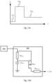
- the control current I c is in this embodiments enabled by the activation of a rush current transistor Q 330 .
- the rush current transistor Q 330 will connect the power source 310 to the shape memory alloy element 151, 251 via an optional rush current limiting element R 330_lim .
- the rush current limiting element R 330_lim will set the rush-level amplitude I 320 of the control current I c .
- the control voltage of the current transistor Q 330 will gradually increase to the level of the power supply 310 as a rush timing capacitor C 330_t is charged via a rush timing resistor R 330_t .
- the control voltage of the current transistor Q 330 will be substantially the same as a voltage provided by the power source 310 and the current transistor Q 330 will disconnect the power source 310 from the shape memory alloy element 151, 251.
- the duration the control current I c is supplied at the rush-level amplitude I 320 by the rush current source 330 is consequently controlled by the dimensioning of the rush timing capacitor C 330_t and the rush timing resistor R 330_t .
- the dimensioning of RC-circuitry and calculation of the corresponding time constant is well known to the skilled person.
- the power supply 310 provides a PWM signal to the current generator 320 and the current generator 320 provides a control current I c that is proportional to a duty cycle of the PWM signal.
- a PWM signal can be controlled by software and the different amplitudes I 320 , I 330 of the control current I c can be configurable.
- the duration the control current I c is supplied at the rush-level amplitude I 330 may in some embodiments be controlled by a control loop where a configuration sensing signal indicates the current configuration of the shape memory alloy element 151, 251.
- the PWM signal can change duty cycle such that a control current Ic of hold-level amplitude I 320 is provided to the shape memory alloy element 151, 251.
- the duty cycle of the PWM signal is controlled by the configuration sensing signal where the control current is kept as low as possible while keeping the shape memory alloy element 151, 251 in the second configuration.
- the configuration sensing signal may be implemented in one of several different ways where the simplest example may be an electromechanical switch arranged to sense the configuration of the shape memory alloy element 151, 251. Another example may be to sense a force that the shape memory alloy element 151, 251 exerts in a direction and use this to generate the configuration sensing signal. Hence, a force sensor may be operatively connected to the shape memory alloy element.
- the duration the control current I c is supplied at the rush-level amplitude I 330 is between 50 ms and 200 ms.
- the hold-level amplitude I 320 is at a level of the first configuration threshold.
- FIG 13e one embodiment of the power source PS2 is shown wherein an operation detection module 340 is arranged between the power supply 310 and the current generator 320 and the optional rush current generator 330.
- the operation detection module 340 is a module arranged to detect if there is manual operation of the patient lift and in turn the locking arrangement 100, 200. This enables the shape memory alloy element 151, 251 to maintain the locking device 151, 251 in its engaged position even if there is power supplied to the power source PS2 and consequently power can be saved since the control current I c can be turned off when no manual operation of the patient lift is performed.
- the operation detection module 340 will supply power to the generator(s) 320, 330 of the power source PS2 only when it detects operation of the patient lift.
- the detection of operation may comprise detecting if e.g. switches operating the patient lift are pressed or a power switch is activated.
- sensors arranged to detect motor activation may be utilised for detecting operation of the patient lift. This may be performed by for example detecting changes in any one of torque or RPM provided by the motor or voltage and current supplied to the motor.
- the operation detection module 340 supplies power to the generator(s) 320, 330 and the control current I c is provided to the shape memory alloy element 151, 251 in any of the ways described earlier.
- a timer is configured to be activated and reset each time an operation is detected and power is supplied to the generator(s) 320, 330 until the timer has reached a predefined or configurable hold off value. Once the hold off value has been reached, the operation detection module 340 is configured to stop supplying power to the generator(s) 320, 330 and consequently the control current I c is turned off. Said timer may be operatively connected to the power supply and/or the separate controller. This is beneficial since in many cases more than one operation will be performed within a limited period of time, e.g. the patient is raised from a bed and shortly thereafter lowered into a wheelchair. Such frequent triggers of the shape memory alloy element 151, 251 will introduce unwanted wear of the system and reduce the lifetime of the locking arrangement 100, 200.
- the operation detection module 340 may be implemented in hardware, software or in a combination of them both.
- the operation detection module may also be considered as part of the current generator 320, especially in embodiments where a controller is used in the power supply PS2.
- the hold off value corresponds to a duration of between 5 and 20 s. This will decrease the stress on the locking arrangement due to limiting rapid switching between the disengaged mode and the engaged mode.
Landscapes
- Health & Medical Sciences (AREA)
- Animal Behavior & Ethology (AREA)
- Nursing (AREA)
- Life Sciences & Earth Sciences (AREA)
- General Health & Medical Sciences (AREA)
- Public Health (AREA)
- Veterinary Medicine (AREA)
- General Engineering & Computer Science (AREA)
- Engineering & Computer Science (AREA)
- Mechanical Engineering (AREA)
- Invalid Beds And Related Equipment (AREA)
- Manipulator (AREA)
- Accommodation For Nursing Or Treatment Tables (AREA)
- Rehabilitation Tools (AREA)
Description
- The present invention relates to a locking arrangement for a patient lift. The present invention further relates to a patient lift comprising such a locking arrangement.
- Patient lifts, also referred to as patient hoists, are commonly used to raise, lower and transfer patients who are disabled or who otherwise have mobility problems. Two common types of patient lifts are stanchion-mounted lifts, also known as floor lifts. and ceiling lifts. Floor lifts often have a hoist assembly which may be disposed at the upper end of a stanchion. The stanchion has a wheeled base, which allows for the lift to be moved along the ground to different locations.
- A lifting member which may be in the form of a spreader bar, such as a two-point attachment spreader bar, a three-point attachment spreader bar, a four-point attachment spreader bar, a five-point attachment spreader bar or a powered spreader bar for adjusting the angle of the spreader bar, for supporting a patient harness or sling descends from the hoist assembly on a strap or a cable. The strap or cable is wound around a motorized drum for raising and lowering the patient harness or sling.
- For example, the lift might be wheeled to position the hoist assembly and lifting member over or adjacent to a patient. The lifting member may then be lowered to receive the patient and subsequently raise the lifting member and patient so that they may be wheeled elsewhere to be lowered and placed. A ceiling lift may be utilized in a similar manner, however the hoist assembly is movably engaged to ceiling-mounted tracks such that the hoist assembly can be moved about the track from location to location.
- A ceiling lift may be described as a motor unit movable along a rail, a flexible member is attached to a spreader bar. The motor unit commonly comprises a transmission, batteries and a control module.
- The transmission is subjected to a number of challenges. For example, the transmission needs to be able to lift a patient, maintain the patient at a prescribed height for a certain period of time and lower the patient. Further, the transmission needs to be able to lift and support a weight of around 450 Kg.
- Manufacturers often use smaller motors able to deliver a high RPM. In order for the smaller motors to be able to support and lift higher loads, the RPM is often reduced and torque increased by means of different types of transmissions.
- Transmissions are in most cases in the form of parallel transmissions in the form of standard gears and strap, pulley and planetary gears or worm gear stages. The toughest challenge for such transmissions is to allow for a locking functionality. The locking allows for the transmission to maintain a load at a fixed position even when the lift is in a powerless state. Parallel transmissions are in themselves not locking but allows for high efficiency. Thus, a mechanical brake is required to allow for the locking functionality. The mechanical brake may be applied directly on the motor shaft to reduce the required braking torque to a minimum. Such a mechanical brake may comprise a solenoid and a braking pad. The solenoid is often expensive and requires a lot of power to operate.
- Worm gear transmissions are often less efficient but allows for locking up to a certain load, often around 110 to 120 Kg. Past said load, the motor has to be provided with power to give a small amount of torque to maintain the load suspended in the lift at the same height. In an emergency situation where the power is down and the patient weighs more than the certain load described above, the patient will slowly move downwards. To counteract such downward movement an electrical brake may be utilized. However, these electrical brakes are expensive and difficult to disengage in case of an emergency.
- In the light of the above, there is a need for a locking or braking arrangement which is associated with a low cost and high efficiency.
- A known braking arrangement is disclosed in
WO 2013/120981 A1 . - According to one aspect a locking arrangement for a patient lift is provided. The locking arrangement is configured to selectively lock the vertical movement of a patient support mounting device connected to a lifting device of the patient lift via a load bearing member.
- The locking arrangement comprises a shape memory alloy element and a locking device. The shape memory alloy element is connected to the locking device and arranged to selectively actuate said locking device to control a locking force on an engagement member mechanically connected to a motor and the load bearing member of the patient lift. The motor is arranged to raise and lower the patient support mounting device.
- The locking arrangement is configured to operate in an engaged mode and a disengaged mode.
- In the engaged mode the shape memory alloy element is in a first configuration and the locking device is in an engaged position in relation to the engagement member for exerting a locking force on the engagement member thereby preventing vertical movement of the patient support mounting device.
- In the disengaged mode the shape memory alloy element is in a second configuration actuating the locking device to a disengaged position in relation to the engagement member thereby enabling vertical movement of the patient support mounting device.
- According to an aspect a patient lift is provided. The patient lift comprises a lifting device, a patient support mounting device and a load bearing member. The patient support mounting device is connected to the lifting device via the load bearing member. Further, the patient lift comprises a locking arrangement according to the above.
- Further objects and features of the present invention will appear from the following detailed description of embodiments of the invention.
- The invention will be described with reference to the accompanying drawings, in which:
-
Figure 1a is a perspective view of elements of a patient lift system. -
Figure 1b is a perspective view of elements of a patient lift system. -
Figure 2 depicts a locking arrangement according to an embodiment implemented in a patient lift system. -
Figure 3 is a cross-section view of a locking arrangement according to an embodiment. -
Figure 4 is a partial longitudinal section view of a locking arrangement according to an embodiment. -
Figure 5 is a perspective view of a locking arrangement according to an embodiment in combination with a motor. -
Figure 6 is a perspective view of a subassembly in the form of a suspension arrangement of a locking arrangement according to an embodiment. -
Figure 7 is a perspective view of a locking arrangement according to an embodiment implemented in a patient lift system. -
Figure 8 is a perspective view of a locking arrangement according to an embodiment in combination with an electric motor. -
Figure 9 is a perspective view of a locking arrangement according to an embodiment in combination with an electric motor and a gear box. -
Figure 10 is a partial longitudinal view of a locking arrangement according to an embodiment. -
Figure 11 is a perspective view of a locking arrangement according to an embodiment. -
Figure 12 is a partial cross-section view of a locking arrangement according to an embodiment. -
Figure 13a is a schematic block diagram of the electrical connections of a locking arrangement according to an embodiment. -
Figure 13b is a schematic block diagram of the electrical connections of a locking arrangement according to an embodiment. -
Figure 13c is a graph depicting the amplitude of the control current of the locking-arrangement. -
Figure 13d is a schematic drawing of the electrical connection of a locking arrangement according to an embodiment. -
Figure 13e is a schematic block diagram of the electrical connections of a locking arrangement according to an embodiment. -
Figures 1a and 1b show a non-limiting example of elements of a patient handling system with a patient lift. The patient lift may be in the form of a patient ceiling lift. A patientsupport mounting device 11 is connected via aload bearing member 12 to alifting device 13 inFigure 1a . The liftingdevice 13 may be arranged to be moveable along atrack 14. The liftingdevice 13 may thus be in engagement with thetrack 14, e.g. movably connected to thetrack 14. The liftingdevice 13 may move along thetrack 14, preferably in both directions. - The lifting
device 13 may be in the form of a trolley movable along saidtrack 14. - The lifting device may comprise a drum for winding of the
load bearing member 12 and motor and transmission for driving said drum. Theload bearing member 12 may be wrapped around said drum for lowering and raising the patientsupport mounting device 11. - In one embodiment, the lifting
device 13 comprises wheels for interfacing with thetrack 14. In one embodiment, the liftingdevice 13 is slidably connected to thetrack 14. - The patient
support mounting device 11 may be a spreader bar or hanger bar. Theload bearing member 12 may be a flexible member such as a strap. Thepatient support 15 may, as shown inFigure 1b , be a sling. - The patient
support mounting device 11 may compriseattachment elements 19 for attaching thepatient support 15 to the patientsupport mounting device 11. The attachment elements may comprise hooks with latches. - The lifting
device 13 is configured to move the patientsupport mounting device 11 between a raised position situated closer to said liftingdevice 13 and a lowered position located more distantly from said liftingdevice 13. The liftingdevice 13 may thus be configured to move the patientsupport mounting device 11 vertically between said raised and lowered position. - Although the patient lift in
Figures 1a-1b is depicted as a ceiling patient lift, the patient lift may also be floor lift with a base comprising a set of wheels for moving the lift across a floor. -
Figures 2-13 discloses aspects of embodiments of locking arrangements for implementation in the patient lift depicted inFigure 1 . - The locking arrangement for the patient lift is configured to selectively lock the vertical movement of the patient
support mounting device 11. The patientsupport mounting device 11 is connected to alifting device 13 of the patient lift via theload bearing member 12. - The locking arrangement comprises a shape
memory alloy element locking device locking device locking device engagement member engagement member motor load bearing member 12 of the patient lift, i.e. themotor load bearing member 12 of the patient lift. Saidmotor support mounting device 11. - The locking arrangement is configured to operate in an engaged mode and a disengaged mode. In the engaged mode, the shape
memory alloy element locking device engagement member support mounting device 11. - In the disengaged mode, the shape
memory alloy element locking device engagement member support mounting device 11. - Compared to known patient lifts implementing locking worm gear transmissions this allows for locking without creeping even when a large load is suspended by means of the patient
support mounting device 11. Furthermore, the shape memory alloy allows for a more cost-efficient and less power consuming solution compared to a solenoid activated mechanical brake. - A shape-memory alloy is as is known in the prior art an alloy which can be deformed in a cold state but returns to a pre-deformed shape when heated. Shape-memory alloys are also known in the prior art as memory metals, memory alloys, smart metals, smart alloys or muscle wires.
- The shape
memory alloy element - The shape
memory alloy element shape memory element locking device engagement member second configuration engagement member - The
locking device memory alloy element memory alloy element locking device memory alloy element locking device - To allow for the
locking device locking device locking device engagement member locking device memory alloy element - Further, the shape
memory alloy element locking device engagement member memory alloy element locking device locking device - This is associated with the advantage of the shape memory alloy element only having to provide a disengaging force, which reduces the wear of the locking arrangement. Furthermore, biased locking device provides for a more reliant and robust locking functionality.
- In an alternative embodiment however, the shape memory alloy element may be arranged to actuate the
locking device shape memory element locking device engagement member second configuration engagement member - In one embodiment, the shape
memory alloy element - The shape
memory alloy element - The locking
arrangement memory alloy element - Each of the first and second configuration may be associated with a temperature interval. The first configuration is associated with a first temperature interval, the second configuration is associated with a second temperature interval.
- The first configuration temperature interval defines a temperature interval substantially lower than the second configuration temperature interval. The first configuration threshold current is thus associated with a temperature of the shape
memory alloy element - Hence, when a current is induced through the shape
memory alloy element memory alloy element - As will be described in more detail with reference to
Figure 13a-e , the current received by the shape metal alloy element may be considered a control current Ic. The control current Ic is of a hold-level amplitude provided by the power source PS1, PS2. Hence, the shapememory alloy element - For example, the shape
memory alloy element - The locking arrangement may be arranged to switch from the disengaged mode to the engaged mode by means of the shape
memory alloy element 151, transitioning from the second configuration to the first configuration in response to receiving a current provided by the power source subceeding, i.e. being smaller than, a second configuration threshold current. This includes the shapememory alloy element - The second threshold current is thus associated with the first configuration temperature interval. Accordingly, the second threshold currents result in the temperature of the smart
metal alloy element - As will be described in more detail with reference to
Figure 13a-e , considering the current received by the shape metal alloy element being the control current Ic. Hence, the shapememory alloy element - For example, if the shape
memory alloy element - The power source may be electrically connected to the
motor motor motor - Thus, the locking arrangement is arranged to switch from the disengaged mode to the engaged mode in response to no power being provided to the
motor motor - The power source PS1, PS2 is further arranged to provide the control current Ic at a rush-level amplitude I330 for a rush current period before providing the control current Ic at the hold-level amplitude I320. A magnitude of the rush-level amplitude I330 being larger than a magnitude of the hold-level amplitude I320. One or more power source PS1, PS2 may be utilized. The power source may be any type of power source known to the skilled person.
- The electrical connection will be further described with reference to
Figure 13a-e . - Referencing
figure 2-12 , thelocking device output shaft engagement member output shaft motor engagement member output shaft -
Figure 2-6 depicts aspects of a locking arrangement according to an embodiment. -
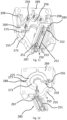
Figure 2 depicts the locking arrangement mounted in thepatient lifting device 113. Themotor 170 of the patient lift is connected to theload bearing member 12 via thetransmission 128. Thelifting device 113 is mountable to therail 114 by means of setwheels 199. -
Figure 3 depicts a cross-section view of the self-locking arrangement. The locking arrangement comprises acasing 159. Thecasing 159 is arranged to receive theengagement member 173. In one embodiment, theengagement member 173 is a friction disc fixated to theoutput shaft 174. - The shape
memory alloy element 151 may be configured to contract in response to a current passing through it. The contracting of the shapememory alloy element 151 pulls thelocking device 155 away from engagement with theengagement member 173. Hence, thelocking device 155 is arranged to disengage from theengagement member 173 by means of contraction of the shapememory alloy element 151 in response to a current exceeding the first configuration threshold current. - The
casing 159 may be arranged to surround theoutput shaft 174. Thecasing 159 may be arranged to be substantially coaxial to theoutput shaft 174. The casing may be substantially cylindrical. - The
locking device 155 may be arranged to be in braking contact with theengagement member 173 while thelocking arrangement 100 operates in the engaged mode. Thelocking device 155 in the engaged position may form a tangent to saidengagement member 173 and in the disengaged position is arranged to be in an offset angle to saidengagement member 173. - the shape
metal alloy element 151 is arranged to allow for thelocking device 155 to be in its engaged position, wherein thelocking device 155 comes into braking contact with theengagement member 173 when the locking arrangement operates in the engaged mode. The shapemetal alloy element 151 may thus be arranged to expand to allow for thelocking device 155 to come into braking contact with theengagement member 173 in response to receiving a current subceeding the second threshold current. - As aforementioned the
locking device 155 maybe biased. For example, by means of being spring-loaded. In one embodiment, thelocking device 155 is in a resilient material. Said resilient material is biased to exert the locking force onto theengagement member 173 and actuating thelocking device 155 to the engaged position when the locking arrangement operates in the engaged mode and the shapememory alloy element 151 is in the first configuration. - The resilient material thus causes the
locking device 155 to come into braking contact with theengagement member 173 while the shapememory alloy element 151 is in the first configuration. Thus, the resilient material causes thelocking device 155 to come into braking contact with theengagement member 173 when the shapememory alloy element 151 transitions from the second to the first configuration, i.e. expands. - When the shape
memory alloy element 151 transitions from the first to the second configuration, the contraction of said shapememory alloy element 151 causes thelocking device 155 to be moved out of braking contact with theengagement member 173. Thereby said transition counteracts the biasing force provided by resilient material of thelocking device 155. - In one embodiment, the
locking device 155 may comprise a friction pad arranged to come into braking contact with theengagement member 173. - Further referencing
Figure 3 and 4 , afirst end portion 156 of thelocking device 155 is attached to an inner surface of thecasing 159. A second end portion, i.e. an opposite end portion, of thelocking device 155 is attached to the shapememory alloy element 151. - The
locking device 155 is arranged to move between the engaged position and the disengaged position in an angle relative a tangent of theengagement member 173. In the engaged position thelocking device 155 is arranged to form a tangent to the engagement member coming into braking contact with saidengagement member 173. Accordingly, the angle in relation to said tangent may be zero. In the disengaged position, thelocking device 155 is inclined relative said tangent to theengagement member 173 to not be in braking contact with saidengagement member 173. - In one embodiment, the
first end portion 156 may be attached to the inner surface of thecasing 159 by means of fastening element(s) 161. - As further depicted in
Figure 4-6 , the shapememory alloy element 151 is arranged in asuspension arrangement 180. Thesuspension arrangement 180 is mounted to thecasing 159. The shape memory alloy element has afirst end 152 and a second, i.e. opposite, end 153. Each of the first and second ends are mounted to thesuspension arrangement 180 such that the shapememory alloy element 151 is arranged to at least partially surround theengagement member 173. The shapememory alloy element 155 has anintermediate portion 154 arranged to extend inwards towards theengagement member 173. Theintermediate portion 154 is connected to thelocking device 155. Saidintermediate portion 154 may thus be arranged to cause the movement of thelocking device 155 between the engaged position and the disengaged position. - The
intermediate portion 154 may be a bent portion of the shapememory alloy element 151 for example in the form a loop-shaped portion. The bent portion is arranged to extend inwardly towards theengagement member 173. The inward end of thebent portion 154 may be attached to thelocking device 155. The end portion may be attached to thesecond end portion 157. - The
suspension arrangement 180 may comprise a first and second port 153 for electrically connecting the shapememory alloy element 151 to the power source. The ports may be connected to the power source via a first andsecond cable 194, 195.ReferencingFigure 4 and5 , thecasing 159 may be arranged to receive themotor 170 therein. Hence, themotor 170 of the patient lift may be mounted inside the casing of the self-locking arrangement. Themotor 170 and the locking arrangement may thus constitute a single motor unit which includes the locking functionality. This enables a more efficient and less complex retro-fitting of the locking arrangement to existing patient lifts. - The
engagement member 173 may be directly mounted to theoutput shaft 174. Theengagement member 173 may be in the form of a friction wheel or disc. The friction wheel may be fixed to theoutput shaft 174. The friction disc may be coaxial with theoutput shaft 174. - Referencing
Figure 4-6 , the suspension arrangement may comprise a guidingchannel 185 for receiving theintermediate portion 154. The guiding channel may extend along thesuspension arrangement 180. A portion of said guidingchannel 185 extends inwardly towards the lockingdevice 155. The shapemetal alloy element 151 extends along the walls of the guidingchannel 185 inwards through the inwardly extending portion through an aperture allowing passage for said shapemetal alloy element 151 towards the lockingdevice 155. Theintermediate portion 154 of the shapemetal alloy element 151 extends along opposite guiding surfaces of said guidingchannel 185, the intermediate portion being in contact with said guiding surfaces. - In one embodiment wherein the
suspension arrangement 180 is mounted to the outside of thecasing 159, the casing may comprise a through-hole for allowing passage of theintermediate portion 154. - The
suspension arrangement 180 may arc shaped and arranged to be mounted to the outer cylindrical surface of thecasing 159. -
Figure 9-12 depicts aspects of another embodiment of the locking arrangement. The lockingarrangement 200 is arranged to mechanically connect themotor 270 and atransmission unit 228 of thepatient lift 213. Thus, the locking arrangement may be arranged to transfer torque between themotor 270 and thetransmission unit 228. Thetransmission unit 228 is arranged to transfer torque from themotor 270 to the load bearing member of the patient lift. - More specifically, the locking
arrangement 200 is arranged to selectively transfer torque between saidmotor 270 andtransmission unit 228. In the engaged mode, the locking arrangement is arranged to disable torque transfer between themotor 270 and thetransmission unit 228. In the disengaged mode, the locking arrangement is arranged to enable torque transfer between themotor 270 and thetransmission unit 228. - The patient lift may thus comprise the
motor 270 andtransmission unit 228. Said motor and transmission unit may be comprised in the lifting device. - The
locking device 250 may be arranged to move between the engaged position and the disengaged position in a direction substantially parallel to theoutput shaft 274. Accordingly, the shapememory alloy element 251 is arranged to move thelocking device 250 between the engaged position and the disengaged position in said direction substantially parallel to theoutput shaft 274. In response to receiving a current exceeding the first threshold current, the shapememory alloy element 251 is arranged to contract to the second configuration causing thelocking device 250 to move to the disengaged position in the direction substantially parallel to theoutput shaft 274. In response to receiving a current subceeding the second threshold current, the shapememory alloy element 251 is arranged to expand to the first configuration causing the locking device to move to the engaged position in the direction the direction substantially parallel to theoutput shaft 274. - The shape
memory alloy element 251 may thus be arranged parallel to theoutput shaft 274. In other words, the shapememory alloy element 251 may be arranged in a direction parallel to theoutput shaft 274. Hence, the shapememory alloy element 251 may be further arranged to contact in a direction parallel to theoutput shaft 274. - As depicted in
Figure 9 , thetransmission unit 228 may be a worm gear transmission. Theoutput shaft 274 may be connected to aworm gear shaft 227. The output shaft may be interfacing with aworm gear wheel 229. The worm gear wheel may be connected to a drum or winch for raising and lowering the patient support mounting device. The load bearing member, which may be a flexible member, may be wrapped around said drum or winch. - Referencing
Figure 10-12 , multiple views of thelocking arrangement 200 are presented. - As most clearly depicted in
Figure 10-11 , afirst portion 253 of the shapememory alloy element 251 may be attached to thelocking device 250. Asecond portion 252 of the shapememory alloy element 251 is fixed. In further detail, saidfirst portion 253 may be attached to anactuated part 255 of thelocking device 250 for moving saidlocking device 250. Preferably saidsecond portion 252 may be arranged to be fixated to themotor 270, i.e. an encasing of themotor 270. - In one embodiment, the locking arrangement may comprise a plurality of shape
memory alloy elements 251. The shapememory alloy elements 251 may extend parallel to each other and to the output shaft. Each shape memory alloy element may be arranged to be electrically connected to the power source. - In one embodiment, the shape
memory alloy element 251 is in the form of a muscle wire. Thefirst portion 253 of the muscle wire may be connected to thelocking device 250, i.e. theactuated part 255 of thelocking device 250, by means of being at least partially wrapped around one ormore protrusions 287 of thelocking device 250, i.e. theactuated part 255. The wrapping of the shapememory alloy element 251 may allow for a more robust connection between the shape metal alloy element and the locking device, capable of carrying a higher load. Thus, a safer and more reliable locking arrangement may be achieved. - According to above described embodiment, a first and second end of the shape
memory alloy element 251 may be fixed, i.e. comprised in the second portion of the shapememory alloy element 251. The first and second end may be arranged to be electrically connected to the power source. The first and second end are fix, preferably said first and second end are arranged to be fixated to themotor 270, i.e. the encasing of the motor. - The locking arrangement may comprise a
suspension console 280. Thesecond portion 252 of the shapememory alloy element 251 is attached to the suspension console. The suspension console may comprise one or more passages arranged to receive the shapememory alloy element 251. Said passages are arranged to extend substantially parallel to theoutput shaft 274. Preferably thesuspension console 280 may comprise ports for receiving the first and second end of the shapememory alloy element 251 and electrically connect the first and second end of the shapememory alloy element 251 to the power source. The suspension console may be mounted to themotor 270. - Further referencing
Figure 10-12 , the lockingarrangement 200 may further comprise ahousing 289 for receiving theoutput shaft 274 and theengagement member 273. The lockingarrangement 200 may further comprise at least onefriction member 275. The at least onefriction member 275 may be arranged in saidhousing 289.Said friction member 275 may be arranged to be in the proximity of theengagement member 273. Accordingly, thelocking device 250 in the engaged position may be arranged to cause the at least onefriction member 275 and theengagement member 273 to come into contact thereby providing a braking torque to theoutput shaft 274. - The
locking device 250 may thus be arranged to in the engaged position push theengagement member 273 towards thefriction member 275 and thereby provide the braking torque to theoutput shaft 274. In one embodiment, thelocking device 250 may be provided with a friction material and arranged to directly coming into contact with theengagement member 273 in the engaged position and thereby provide braking torque to the output shaft. Thefriction member 275 may be movably arranged in the casing. - The
friction member 275 may be arranged in a recess of the housing, said recess enabling movement of thefriction member 275 substantially parallel to the direction of theoutput shaft 274. - In one embodiment, which is depicted in
Figure 9-12 , the locking device may be biased by means of further comprising a biasingpart 256. The biasingpart 256 is spring loaded for exerting a locking force onto theengagement member 273. The biasingpart 256 is arranged to engage theactuated part 255 for actuating thelocking device 250 to the engaged position when the locking arrangement operates in the engaged mode. - Further, the biasing
part 256 may be arranged to engage theactuated part 255 upon the locking device moving from the engaged position towards the disengaged position. - The biasing
part 256 may comprise at least oneabutment heel 269 arranged to latch onto theactuated part 255. Theabutment heel 269 may provide a latching surface abutting to theactuated part 255. Upon thelocking device 250 moving from the engaged position towards the disengaged position, the biasingpart 256 is arranged to be pushed away from theengagement member 273 by the actuatedpart 255. Hence the shapemetal alloy element 251 is arranged to push the biasingpart 256 against the spring force exerted by said biasingpart 256 upon said shapemetal alloy element 251 transitioning from the first configuration to the second configuration. - Accordingly, the
output shaft 274 may extend distally, whereby the first end of theshape metal alloy 251 may be a distal end of said shapemetal alloy element 251. The latching surface of theabutment heel 269 may be a distal surface of the biasingpart 256. Said latching surface is in abutment with a proximal surface of theactuated part 255, whereby the actuated part is arranged to push the biasing part away, i.e. in a proximal direction, from the engagement member by the proximal surface of the actuated part255 pushing thedistal surface 256 of the biasingpart 256. - When the shape
memory alloy element 251 transitions from the second configuration to the first configuration the biasing part reaches its locking position, i.e. the biasing part locks theengagement member 274. Thus, the expansion of the shapememory alloy element 251 causes the biasing part to push thelocking device 250 to its engaged position, whereby the locking force is provided. - In an alternative embodiment the biasing
part 256 may be directly connected to theactuated part 255. Thus, the biasingpart 256 may be attached to the actuated 255 for example by means of fastening elements such as screws. - Compared to the fixed attachment, the embodiment implementing the abutment heel allows for the
actuated part 255 and the biasingpart 256 to not be completely aligned and still provide the necessary locking force, whereby the locking arrangement is less susceptible to wear and functional issues due to inaccurate tolerances. Thus, a more stable and efficient locking arrangement may be achieved. As depicted inFigure 11 , biasing part may comprise a pair of abutment heels. A first abutment heel may extend outwardly in a first direction, whereby a second abutment heel may extend outwardly in a second direction opposite to the first direction. - The
housing 289 may comprise one or morelocking device tracks 298 for supporting thelocking device 250 along its movement between the engaged position and the disengaged position. The guided movement of the locking device provided by the locking device tracks allows for a more exact and reliable locking. Preferably said locking device tracks may be arranged to support the actuatedpart 255 of thelocking device 250. - The
locking device tracks 298 may be arranged to extend substantially parallel to theoutput shaft 274. - In one embodiment, the
actuated part 255 is substantially U-shaped, whereby thehousing 289 may comprise a first and second locking device tracks for receiving a first and second flange of said U-shaped actuatedpart 255. - In one embodiment, the
actuated part 255 is provided with one ormore wheels 299 arranged to run in said one or more locking device tracks. - Further referencing
Figure 10-12 , the biasingpart 256 may be connected to a fix surface by means ofsprings 259. Said springs may be connected to themotor 270, i.e. the encasing of themotor 270. In one embodiment, the springs may extend substantially parallel to theoutput shaft 274. - As depicted in
Figure 10-12 , theengagement member 273 may be as earlier described in the form of a friction disc or wheel fixated to theoutput shaft 274. Theengagement member 273 extends substantially orthogonal to theoutput shaft 274. - The at least one
friction member 275 may be a friction washer. Said at least one friction washer may be an annular friction washer with an aperture for receiving theoutput shaft 274. The at least onefriction member 275 is arranged to be coaxial to theengagement member 273 and theoutput shaft 274. The at least onefriction element 275 may be coaxial to the biasingpart 256. The biasing part may comprise an aperture for receiving theoutput shaft 274, i.e. allowing passage of theoutput shaft 274. - Each of the at least one
friction member 275 may be movably arranged in thehousing 289. Each of the at least onefriction member 275 may be arranged to move along a direction substantially parallel to theoutput shaft 273. Hence, the biasingpart 256 is arranged to push the at least onefriction member 275 onto theengagement member 274 thereby locking theoutput shaft 274. - Said at least one
friction member 275 may be provided with at least oneguide element 277. Thehousing 289 may comprise acorresponding guide element 288. Thecorresponding guide element 288 is arranged to guide the at least onefriction member 275 in a direction substantially parallel to theoutput shaft 274. As depicted inFigure 12 , the at least one guide element may be a guiding protrusion, whereby theguide element 288 may be a guiding channel extending in the housing in a direction substantially parallel to theoutput shaft 274. Said guiding channel is arranged to receive the guiding protrusion. - In one embodiment, the locking arrangement may comprise two
friction members 275. Thefriction members 275 may be arranged in the recess of thehousing 289 at a distance from each other for receiving theengagement member 274 there between. - Further referencing
Figure 9-12 , theoutput shaft 274 extends distally, whereby the first friction member is a distal friction member and the second friction member is a proximal friction member. The biasingpart 256 may be arranged to come into contact with the proximal friction member to push said proximal friction member to a proximal surface of theengagement member 273 when thelocking device 250 is in the engaged position. Thus, the biasingpart 256 pushes the proximal friction member towards the engagement member and the distal friction member thereby locking theengagement member 273. - According to an aspect a patient lift comprising the locking arrangement according to any of the embodiments described above is provided. Hence, said patient lift comprises the
lifting device support mounting device 11, theload bearing member 12. The patientsupport mounting device 11 is connected to thelifting device load bearing member 12. The patient lift further comprises the lockingarrangement -
Figures 13a-e discloses embodiments of the circuitry for controlling the locking arrangement. With reference toFigure 13a-b , the patient lift comprises the power source PS1, PS2. The power source PS1, PS2 is electrically connected to themotor motor motor motor memory alloy element memory alloy element memory alloy element power supply 310 which is typically connected to mains power but may in all embodiments be arranged to comprise one or more batteries suitable to supply the drive current Id to themotor memory alloy element motor memory alloy element - In one embodiment of the power source PS1, PS2, as seen in
Figure 13b , the power source PS1, PS2 comprises thepower supply 310 and acurrent generator 320. As mentioned earlier, thepower supply 310 may be a mains connection, battery or any other suitable means for providing power such as a low voltage DC or AC. The skilled person has knowledge of how to adaptdifferent power supplies 310 to suit the power source PS1, PS2. Thecurrent generator 320 may be implemented in numerous different ways. The simplest implementation is by having the current generator connect the power source directly to the shapememory alloy element memory alloy element memory alloy element power source 310 itself is capable of supplying such currents. Such acurrent generator 320 may be problematic as it will consume a fair amount of power but it will be as quick as can be in transitioning the shapememory alloy element locking arrangement locking arrangement power supply 310 and the shapememory alloy element memory alloy element current generator 320 are suitable off the shelf components e.g. a transistor that is controlled from thepower supply 310, the NCP3066 buck/boost/inverting, Regulator, Switching, Constant Current generator from ON Semiconductor or any other current controlling means. - The shape
memory alloy element memory alloy element memory alloy element memory alloy element memory alloy element Figure 13b , in order to make the transition from the engaged position to the disengaged positon as fast as possible without consuming too much current, a rushcurrent source 330 may be comprised in the power source PS1, PS2. The rushcurrent source 330 is arranged to provide a comparably high control current Ic for a limited period of time allowing the shapememory alloy element current generator 320. One advantage of such an arrangement is that the current consumption in steady state, disengaged position, can be reduced whilst keeping the time is takes to transition from the engaged position to the disengaged position as short as possible. This is provided for by the dual current sources where the rushcurrent generator 330 provides the control current Ic for a comparably short period of time before control current Ic is provided solely by thecurrent generator 320. It should be mentioned that the both the rushcurrent generator 330 and thecurrent generator 320 can work in parallel during the transition from the engaged position to the disengaged position by the shapememory alloy element - In
Figure 13c , a graph of the amplitude of the control current Ic is shown as over time t as a dotted line in. Initially, the control current Ic is off and an at off-level amplitude Ioff. At a point in time, the shapememory alloy element current source 330. After a period of time, the rushcurrent source 330 stops providing current and the control current Ic is supplied at a hold-level amplitude I320 supplied by thecurrent source 320. - The rush
current source 330 may be implemented in many ways. One embodiment of the rushcurrent source 330 is shown by the simplified schematic inFigure 13d . The control current Ic is in this embodiments enabled by the activation of a rush current transistor Q330. As power is supplied to the rush current generator by thepower source 310, the rush current transistor Q330 will connect thepower source 310 to the shapememory alloy element power supply 310 as a rush timing capacitor C330_t is charged via a rush timing resistor R330_t. Once the rush timing capacitor C330_t is charged, the control voltage of the current transistor Q330 will be substantially the same as a voltage provided by thepower source 310 and the current transistor Q330 will disconnect thepower source 310 from the shapememory alloy element current source 330 is consequently controlled by the dimensioning of the rush timing capacitor C330_t and the rush timing resistor R330_t. The dimensioning of RC-circuitry and calculation of the corresponding time constant is well known to the skilled person. - In one embodiment, not shown, of the power supply PS1, PS2, the
power supply 310, or a separate controller, provides a PWM signal to thecurrent generator 320 and thecurrent generator 320 provides a control current Ic that is proportional to a duty cycle of the PWM signal. Such an embodiment is beneficial as it allows the current generator to directly generate a control current Ic of a rush-level amplitude I320 simply by providing it with a PWM signal of a comparably higher duty cycle compared to the duty cycle provided to the current generator when it is to provide a control current Ic of hold-level amplitude I320. The PWM signal can be controlled by software and the different amplitudes I320, I330 of the control current Ic can be configurable. The duration the control current Ic is supplied at the rush-level amplitude I330 may in some embodiments be controlled by a control loop where a configuration sensing signal indicates the current configuration of the shapememory alloy element memory alloy element memory alloy element memory alloy element memory alloy element current generator 320. As soon as the shapememory alloy element current generator 320. The configuration sensing signal may be implemented in one of several different ways where the simplest example may be an electromechanical switch arranged to sense the configuration of the shapememory alloy element memory alloy element - In one embodiment of the power source PS1, PS2, the duration the control current Ic is supplied at the rush-level amplitude I330 is between 50 ms and 200 ms.
- In one embodiment, the hold-level amplitude I320 is at a level of the first configuration threshold.
- In
Figure 13e , one embodiment of the power source PS2 is shown wherein anoperation detection module 340 is arranged between thepower supply 310 and thecurrent generator 320 and the optional rushcurrent generator 330. This embodiment of the power source PS2 may be combined with any of the other embodiments and examples presented herein. Theoperation detection module 340 is a module arranged to detect if there is manual operation of the patient lift and in turn thelocking arrangement memory alloy element locking device operation detection module 340 will supply power to the generator(s) 320, 330 of the power source PS2 only when it detects operation of the patient lift. The detection of operation may comprise detecting if e.g. switches operating the patient lift are pressed or a power switch is activated. Alternatively, or in addition, sensors arranged to detect motor activation may be utilised for detecting operation of the patient lift. This may be performed by for example detecting changes in any one of torque or RPM provided by the motor or voltage and current supplied to the motor. Once operation is detected, theoperation detection module 340 supplies power to the generator(s) 320, 330 and the control current Ic is provided to the shapememory alloy element - In one embodiment of the operation detection module, a timer is configured to be activated and reset each time an operation is detected and power is supplied to the generator(s) 320, 330 until the timer has reached a predefined or configurable hold off value. Once the hold off value has been reached, the
operation detection module 340 is configured to stop supplying power to the generator(s) 320, 330 and consequently the control current Ic is turned off. Said timer may be operatively connected to the power supply and/or the separate controller. This is beneficial since in many cases more than one operation will be performed within a limited period of time, e.g. the patient is raised from a bed and shortly thereafter lowered into a wheelchair. Such frequent triggers of the shapememory alloy element locking arrangement - It should be mentioned that the
operation detection module 340 may be implemented in hardware, software or in a combination of them both. The operation detection module may also be considered as part of thecurrent generator 320, especially in embodiments where a controller is used in the power supply PS2. - In one embodiment of the operation detection module, the hold off value corresponds to a duration of between 5 and 20 s. This will decrease the stress on the locking arrangement due to limiting rapid switching between the disengaged mode and the engaged mode.
- The invention has been described above in detail with reference to embodiments thereof. However, as is readily understood by those skilled in the art, other embodiments are equally possible within the scope of the present invention, as defined by the appended claims.
Claims (15)
- A locking arrangement (100, 200) for a patient lift configured to selectively lock the vertical movement of a patient support mounting device (11) connected to a lifting device (13, 113, 213) of the patient lift via a load bearing member (12),the locking arrangement comprising a shape memory alloy element (151, 251) and a locking device (155, 250), the shape memory alloy element (151, 251) being connected to the locking device (155, 250) and arranged to selectively actuate said locking device (155, 250) to control a locking force on an engagement member (173, 273) mechanically connected to a motor (170, 270) and the load bearing member (12) of the patient lift, the motor (170, 270) being arranged to raise and lower the patient support mounting device (11),the locking arrangement being configured to operate in:an engaged mode wherein the shape memory alloy element (151, 251) is in a first configuration and the locking device (155, 250) is in an engaged position in relation to the engagement member (173, 273) for exerting a locking force on the engagement member (173, 273) thereby preventing vertical movement of the patient support mounting device (11);a disengaged mode wherein the shape memory alloy element (151, 251) is in a second configuration actuating the locking device (155, 250) to a disengaged position in relation to the engagement member (173, 273) thereby enabling vertical movement of the patient support mounting device (11),wherein the shape memory alloy element (151, 251) is arranged to be electrically connected to at least one power source (PS1, PS2) for selectively transitioning between the first and second configuration.
- Locking arrangement (100, 200) according to claim 1, wherein the locking arrangement (100, 200) is arranged to switch from the engaged mode to the disengaged mode by means of the shape memory alloy element (151, 251) transitioning from the first configuration to the second configuration in response to receiving a current provided by said power source (PS1, PS2) exceeding a first configuration threshold current.
- Locking arrangement (100, 200) according to claim 1 or 2, wherein the locking arrangement (100, 200) is arranged to switch from the disengaged mode to the engaged mode by means of the shape memory alloy element (151, 251) transitioning from the second configuration to the first configuration in response to receiving a current provided by the power source (PS1, PS2) subceeding a second configuration threshold current.
- Locking arrangement (100, 200) according to any one of the preceding claims, wherein the power source (PS1, PS2) is electrically connected to the motor (170, 270) for driving said motor (170, 270).
- Locking arrangement (100, 200) according to any one of the preceding claims, wherein the shape memory alloy element (151, 251) is a muscle wire.
- Locking arrangement (100, 200) according to any one of preceding claims, wherein the locking device (155, 250) is a braking member arranged to selectively provide a braking torque to an output shaft (174, 274) of the patient lift via the engagement member (173, 273), the output shaft (174, 274) being connected to the motor (170. 270).
- Locking arrangement (100, 200) according to claim 6, wherein the engagement member (173, 273) is a friction disc fixated to the output shaft (174, 274).
- Locking arrangement (100, 200) according to any of the preceding claims, wherein the locking device (155, 250) is biased to exert the locking force onto the engagement member (173, 273) and actuating the locking device (155, 250) to the engaged position when the locking arrangement operates in the engaged mode and the shape memory alloy element (151, 251) is in the first configuration, and whereby the shape memory alloy element (151, 251) is arranged to actuate the locking device (155, 250) to the disengaged position in relation to the engagement member (173, 273) by being in the second configuration when the locking arrangement operates in the disengaged mode.
- Locking arrangement (100) according to any one of the preceding claims, further comprising a casing (159) arranged to receive the engagement member (173).
- Locking arrangement (100) according to claim 9, wherein a first end portion (156) of the locking device (155) is attached to an inner surface of the casing (159) and a second end portion (157) of the locking device (155) is attached to the shape memory alloy element (151).
- Locking arrangement (100) according to any one of claim 9 to 10, wherein the shape memory alloy element (151) is arranged in a suspension arrangement (180) mounted to the casing (159), whereby the shape memory alloy element (151) has a first end (152) and second end (153) mounted to the suspension arrangement (180) such that the shape memory alloy element (151) is arranged to at least partially surround the engagement member (173), the shape memory alloy element (151) having an intermediate portion (154) arranged to extend inwards towards the engagement member (173), the intermediate portion (154) being connected to the locking device (155).
- Locking arrangement (200) according to any one of claim 1 to 8, further arranged to mechanically connect the motor (270) and a transmission unit (228) of the patient lift.
- Locking arrangement according to any one of claim 6 to 8 or 12, wherein the locking device (250) is arranged to move between the engaged position and the disengaged position in a direction substantially parallel to the output shaft (274).
- Locking arrangement (200) according to claim 13, whereby a first portion (253) of the shape memory alloy element (251) is attached to an actuated part (255) of the locking device (250) for moving said locking device (250) and a second portion (252) of the shape memory alloy element (251) is fix.
- A patient lift comprising a lifting device (13, 113, 213), a patient support mounting device (11) and a load bearing member (12), the patient support mounting device (11) being connected to the lifting device (13, 113, 213) via the load bearing member (12), the patient lift further comprising a locking arrangement (100, 200) according to any one of the claims 1-14.
Applications Claiming Priority (2)
| Application Number | Priority Date | Filing Date | Title |
|---|---|---|---|
| SE1951088A SE543644C2 (en) | 2019-09-26 | 2019-09-26 | Locking arrangement for patient lift |
| PCT/EP2020/075618 WO2021058308A1 (en) | 2019-09-26 | 2020-09-14 | Locking arrangement for patient lift |
Publications (2)
| Publication Number | Publication Date |
|---|---|
| EP4034064A1 EP4034064A1 (en) | 2022-08-03 |
| EP4034064B1 true EP4034064B1 (en) | 2024-11-27 |
Family
ID=72521606
Family Applications (1)
| Application Number | Title | Priority Date | Filing Date |
|---|---|---|---|
| EP20772259.6A Active EP4034064B1 (en) | 2019-09-26 | 2020-09-14 | Locking arrangement for patient lift |
Country Status (7)
| Country | Link |
|---|---|
| US (1) | US12133824B2 (en) |
| EP (1) | EP4034064B1 (en) |
| DK (1) | DK4034064T3 (en) |
| ES (1) | ES3014538T3 (en) |
| PL (1) | PL4034064T3 (en) |
| SE (1) | SE543644C2 (en) |
| WO (1) | WO2021058308A1 (en) |
Family Cites Families (7)
| Publication number | Priority date | Publication date | Assignee | Title |
|---|---|---|---|---|
| JP2883060B2 (en) * | 1997-01-20 | 1999-04-19 | 株式会社アラマキテクニカ | lift device |
| CA2369668C (en) * | 2002-01-28 | 2010-05-04 | Waverley Glen Systems Ltd. | Personal lift device |
| DE102006037650B4 (en) * | 2006-02-09 | 2018-09-13 | Otto Egelhof Gmbh & Co. Kg | linear motion |
| CA2692894C (en) * | 2010-02-12 | 2017-06-27 | Bhm Medical Inc. | Lift apparatus and system |
| DE102012202257B4 (en) * | 2012-02-15 | 2014-10-30 | ebm-papst ZEITLAUF GmbH & Co. KG | Lifting device, in particular patient hoist, with roll-off protection |
| CN105829228B (en) * | 2013-12-19 | 2017-12-26 | 因温特奥股份公司 | Method for the actuator of lift facility and for operating such actuator |
| US11771606B2 (en) * | 2018-09-20 | 2023-10-03 | Caleigh M. Waskowicz | Ambulatory assist device |
-
2019
- 2019-09-26 SE SE1951088A patent/SE543644C2/en unknown
-
2020
- 2020-09-14 ES ES20772259T patent/ES3014538T3/en active Active
- 2020-09-14 DK DK20772259.6T patent/DK4034064T3/en active
- 2020-09-14 EP EP20772259.6A patent/EP4034064B1/en active Active
- 2020-09-14 PL PL20772259.6T patent/PL4034064T3/en unknown
- 2020-09-14 US US17/763,795 patent/US12133824B2/en active Active
- 2020-09-14 WO PCT/EP2020/075618 patent/WO2021058308A1/en not_active Ceased
Also Published As
| Publication number | Publication date |
|---|---|
| PL4034064T3 (en) | 2025-04-28 |
| US20220339049A1 (en) | 2022-10-27 |
| EP4034064A1 (en) | 2022-08-03 |
| CA3155447A1 (en) | 2021-04-01 |
| SE543644C2 (en) | 2021-05-11 |
| DK4034064T3 (en) | 2025-02-24 |
| WO2021058308A1 (en) | 2021-04-01 |
| US12133824B2 (en) | 2024-11-05 |
| ES3014538T3 (en) | 2025-04-23 |
| SE1951088A1 (en) | 2021-03-27 |
Similar Documents
| Publication | Publication Date | Title |
|---|---|---|
| US11744359B2 (en) | Pneumatic lifting table frame and lifting table | |
| CN102770365B (en) | Lifting devices and systems | |
| EP1879536B1 (en) | A handling system for lifting or moving a person, a weighting system and method of lifting and moving a person | |
| CA3155447C (en) | Locking arrangement for patient lift | |
| TW201636292A (en) | Rescue equipment and lifts | |
| CN108059042A (en) | Electrical autonomous elevator device | |
| US12133824B2 (en) | Locking arrangement for patient lift | |
| US20250281341A1 (en) | Drive system for patient lift | |
| US4104749A (en) | Electrically adjustable bed frame | |
| CN107428470A (en) | Conveyor installation with improved wiring arrangement for drive motors and brakes of conveyor rollers and operating method therefor | |
| KR101332586B1 (en) | Elevator door controller system | |
| MX2015005493A (en) | Apparatus and method for providing emergency cpr functionality on a patient support surface. | |
| HK40093994A (en) | Drive system for patient lift | |
| HK40093994B (en) | Drive system for patient lift | |
| KR101992975B1 (en) | Controller for hoist capable of multi speed control and hoist including the same controller | |
| RU2814531C1 (en) | Patient lifting and moving device | |
| KR100859180B1 (en) | Hook lifting device for stage device | |
| US20190100929A1 (en) | Hoist system with direct current power supply | |
| CN120777729B (en) | Device with water tank | |
| KR100256044B1 (en) | Hanger`s lifter for leaf tobacco desicator | |
| CN119372891A (en) | A household appliance |
Legal Events
| Date | Code | Title | Description |
|---|---|---|---|
| STAA | Information on the status of an ep patent application or granted ep patent |
Free format text: STATUS: UNKNOWN |
|
| STAA | Information on the status of an ep patent application or granted ep patent |
Free format text: STATUS: THE INTERNATIONAL PUBLICATION HAS BEEN MADE |
|
| PUAI | Public reference made under article 153(3) epc to a published international application that has entered the european phase |
Free format text: ORIGINAL CODE: 0009012 |
|
| STAA | Information on the status of an ep patent application or granted ep patent |
Free format text: STATUS: REQUEST FOR EXAMINATION WAS MADE |
|
| 17P | Request for examination filed |
Effective date: 20220330 |
|
| AK | Designated contracting states |
Kind code of ref document: A1 Designated state(s): AL AT BE BG CH CY CZ DE DK EE ES FI FR GB GR HR HU IE IS IT LI LT LU LV MC MK MT NL NO PL PT RO RS SE SI SK SM TR |
|
| DAV | Request for validation of the european patent (deleted) | ||
| DAX | Request for extension of the european patent (deleted) | ||
| GRAP | Despatch of communication of intention to grant a patent |
Free format text: ORIGINAL CODE: EPIDOSNIGR1 |
|
| STAA | Information on the status of an ep patent application or granted ep patent |
Free format text: STATUS: GRANT OF PATENT IS INTENDED |
|
| INTG | Intention to grant announced |
Effective date: 20240719 |
|
| GRAS | Grant fee paid |
Free format text: ORIGINAL CODE: EPIDOSNIGR3 |
|
| GRAA | (expected) grant |
Free format text: ORIGINAL CODE: 0009210 |
|
| STAA | Information on the status of an ep patent application or granted ep patent |
Free format text: STATUS: THE PATENT HAS BEEN GRANTED |
|
| AK | Designated contracting states |
Kind code of ref document: B1 Designated state(s): AL AT BE BG CH CY CZ DE DK EE ES FI FR GB GR HR HU IE IS IT LI LT LU LV MC MK MT NL NO PL PT RO RS SE SI SK SM TR |
|
| REG | Reference to a national code |
Ref country code: GB Ref legal event code: FG4D |
|
| REG | Reference to a national code |
Ref country code: CH Ref legal event code: EP |
|
| REG | Reference to a national code |
Ref country code: IE Ref legal event code: FG4D |
|
| REG | Reference to a national code |
Ref country code: DE Ref legal event code: R096 Ref document number: 602020042107 Country of ref document: DE |
|
| REG | Reference to a national code |
Ref country code: DK Ref legal event code: T3 Effective date: 20250220 |
|
| REG | Reference to a national code |
Ref country code: NL Ref legal event code: FP |
|
| REG | Reference to a national code |
Ref country code: SE Ref legal event code: TRGR |
|
| REG | Reference to a national code |
Ref country code: LT Ref legal event code: MG9D |
|
| P01 | Opt-out of the competence of the unified patent court (upc) registered |
Free format text: CASE NUMBER: APP_8633/2025 Effective date: 20250220 |
|
| PG25 | Lapsed in a contracting state [announced via postgrant information from national office to epo] |
Ref country code: PT Free format text: LAPSE BECAUSE OF FAILURE TO SUBMIT A TRANSLATION OF THE DESCRIPTION OR TO PAY THE FEE WITHIN THE PRESCRIBED TIME-LIMIT Effective date: 20250327 Ref country code: HR Free format text: LAPSE BECAUSE OF FAILURE TO SUBMIT A TRANSLATION OF THE DESCRIPTION OR TO PAY THE FEE WITHIN THE PRESCRIBED TIME-LIMIT Effective date: 20241127 Ref country code: IS Free format text: LAPSE BECAUSE OF FAILURE TO SUBMIT A TRANSLATION OF THE DESCRIPTION OR TO PAY THE FEE WITHIN THE PRESCRIBED TIME-LIMIT Effective date: 20250327 |
|
| PG25 | Lapsed in a contracting state [announced via postgrant information from national office to epo] |
Ref country code: FI Free format text: LAPSE BECAUSE OF FAILURE TO SUBMIT A TRANSLATION OF THE DESCRIPTION OR TO PAY THE FEE WITHIN THE PRESCRIBED TIME-LIMIT Effective date: 20241127 |
|
| PG25 | Lapsed in a contracting state [announced via postgrant information from national office to epo] |
Ref country code: BG Free format text: LAPSE BECAUSE OF FAILURE TO SUBMIT A TRANSLATION OF THE DESCRIPTION OR TO PAY THE FEE WITHIN THE PRESCRIBED TIME-LIMIT Effective date: 20241127 |
|
| PG25 | Lapsed in a contracting state [announced via postgrant information from national office to epo] |
Ref country code: NO Free format text: LAPSE BECAUSE OF FAILURE TO SUBMIT A TRANSLATION OF THE DESCRIPTION OR TO PAY THE FEE WITHIN THE PRESCRIBED TIME-LIMIT Effective date: 20250227 |
|
| REG | Reference to a national code |
Ref country code: ES Ref legal event code: FG2A Ref document number: 3014538 Country of ref document: ES Kind code of ref document: T3 Effective date: 20250423 |
|
| PG25 | Lapsed in a contracting state [announced via postgrant information from national office to epo] |
Ref country code: GR Free format text: LAPSE BECAUSE OF FAILURE TO SUBMIT A TRANSLATION OF THE DESCRIPTION OR TO PAY THE FEE WITHIN THE PRESCRIBED TIME-LIMIT Effective date: 20250228 Ref country code: LV Free format text: LAPSE BECAUSE OF FAILURE TO SUBMIT A TRANSLATION OF THE DESCRIPTION OR TO PAY THE FEE WITHIN THE PRESCRIBED TIME-LIMIT Effective date: 20241127 |
|
| PG25 | Lapsed in a contracting state [announced via postgrant information from national office to epo] |
Ref country code: RS Free format text: LAPSE BECAUSE OF FAILURE TO SUBMIT A TRANSLATION OF THE DESCRIPTION OR TO PAY THE FEE WITHIN THE PRESCRIBED TIME-LIMIT Effective date: 20250227 |
|
| PG25 | Lapsed in a contracting state [announced via postgrant information from national office to epo] |
Ref country code: SM Free format text: LAPSE BECAUSE OF FAILURE TO SUBMIT A TRANSLATION OF THE DESCRIPTION OR TO PAY THE FEE WITHIN THE PRESCRIBED TIME-LIMIT Effective date: 20241127 |
|
| PG25 | Lapsed in a contracting state [announced via postgrant information from national office to epo] |
Ref country code: EE Free format text: LAPSE BECAUSE OF FAILURE TO SUBMIT A TRANSLATION OF THE DESCRIPTION OR TO PAY THE FEE WITHIN THE PRESCRIBED TIME-LIMIT Effective date: 20241127 |
|
| PG25 | Lapsed in a contracting state [announced via postgrant information from national office to epo] |
Ref country code: RO Free format text: LAPSE BECAUSE OF FAILURE TO SUBMIT A TRANSLATION OF THE DESCRIPTION OR TO PAY THE FEE WITHIN THE PRESCRIBED TIME-LIMIT Effective date: 20241127 |
|
| PG25 | Lapsed in a contracting state [announced via postgrant information from national office to epo] |
Ref country code: SK Free format text: LAPSE BECAUSE OF FAILURE TO SUBMIT A TRANSLATION OF THE DESCRIPTION OR TO PAY THE FEE WITHIN THE PRESCRIBED TIME-LIMIT Effective date: 20241127 |
|
| REG | Reference to a national code |
Ref country code: DE Ref legal event code: R097 Ref document number: 602020042107 Country of ref document: DE |
|
| REG | Reference to a national code |
Ref country code: CH Ref legal event code: U11 Free format text: ST27 STATUS EVENT CODE: U-0-0-U10-U11 (AS PROVIDED BY THE NATIONAL OFFICE) Effective date: 20251001 |
|
| PLBE | No opposition filed within time limit |
Free format text: ORIGINAL CODE: 0009261 |
|
| STAA | Information on the status of an ep patent application or granted ep patent |
Free format text: STATUS: NO OPPOSITION FILED WITHIN TIME LIMIT |
|
| REG | Reference to a national code |
Ref country code: CH Ref legal event code: L10 Free format text: ST27 STATUS EVENT CODE: U-0-0-L10-L00 (AS PROVIDED BY THE NATIONAL OFFICE) Effective date: 20251008 |
|
| PGFP | Annual fee paid to national office [announced via postgrant information from national office to epo] |
Ref country code: DE Payment date: 20250919 Year of fee payment: 6 Ref country code: DK Payment date: 20250923 Year of fee payment: 6 |
|
| PGFP | Annual fee paid to national office [announced via postgrant information from national office to epo] |
Ref country code: NL Payment date: 20250918 Year of fee payment: 6 Ref country code: IT Payment date: 20250923 Year of fee payment: 6 Ref country code: PL Payment date: 20250904 Year of fee payment: 6 |
|
| PGFP | Annual fee paid to national office [announced via postgrant information from national office to epo] |
Ref country code: GB Payment date: 20250919 Year of fee payment: 6 |
|
| PGFP | Annual fee paid to national office [announced via postgrant information from national office to epo] |
Ref country code: FR Payment date: 20250922 Year of fee payment: 6 Ref country code: AT Payment date: 20250919 Year of fee payment: 6 |
|
| PGFP | Annual fee paid to national office [announced via postgrant information from national office to epo] |
Ref country code: SE Payment date: 20250918 Year of fee payment: 6 |
|
| PGFP | Annual fee paid to national office [announced via postgrant information from national office to epo] |
Ref country code: CZ Payment date: 20250908 Year of fee payment: 6 |
|
| 26N | No opposition filed |
Effective date: 20250828 |
|
| PGFP | Annual fee paid to national office [announced via postgrant information from national office to epo] |
Ref country code: CH Payment date: 20251001 Year of fee payment: 6 |
|
| PGFP | Annual fee paid to national office [announced via postgrant information from national office to epo] |
Ref country code: ES Payment date: 20251030 Year of fee payment: 6 |