EP4034047B1 - Zwischenwirbelvorrichtungen - Google Patents
Zwischenwirbelvorrichtungen Download PDFInfo
- Publication number
- EP4034047B1 EP4034047B1 EP20796879.3A EP20796879A EP4034047B1 EP 4034047 B1 EP4034047 B1 EP 4034047B1 EP 20796879 A EP20796879 A EP 20796879A EP 4034047 B1 EP4034047 B1 EP 4034047B1
- Authority
- EP
- European Patent Office
- Prior art keywords
- component
- superior
- core component
- lateral
- inferior
- Prior art date
- Legal status (The legal status is an assumption and is not a legal conclusion. Google has not performed a legal analysis and makes no representation as to the accuracy of the status listed.)
- Active
Links
Images

Classifications
-
- A—HUMAN NECESSITIES
- A61—MEDICAL OR VETERINARY SCIENCE; HYGIENE
- A61F—FILTERS IMPLANTABLE INTO BLOOD VESSELS; PROSTHESES; DEVICES PROVIDING PATENCY TO, OR PREVENTING COLLAPSING OF, TUBULAR STRUCTURES OF THE BODY, e.g. STENTS; ORTHOPAEDIC, NURSING OR CONTRACEPTIVE DEVICES; FOMENTATION; TREATMENT OR PROTECTION OF EYES OR EARS; BANDAGES, DRESSINGS OR ABSORBENT PADS; FIRST-AID KITS
- A61F2/00—Filters implantable into blood vessels; Prostheses, i.e. artificial substitutes or replacements for parts of the body; Appliances for connecting them with the body; Devices providing patency to, or preventing collapsing of, tubular structures of the body, e.g. stents
- A61F2/02—Prostheses implantable into the body
- A61F2/30—Joints
- A61F2/44—Joints for the spine, e.g. vertebrae, spinal discs
- A61F2/4455—Joints for the spine, e.g. vertebrae, spinal discs for the fusion of spinal bodies, e.g. intervertebral fusion of adjacent spinal bodies, e.g. fusion cages
- A61F2/447—Joints for the spine, e.g. vertebrae, spinal discs for the fusion of spinal bodies, e.g. intervertebral fusion of adjacent spinal bodies, e.g. fusion cages substantially parallelepipedal, e.g. having a rectangular or trapezoidal cross-section
-
- A—HUMAN NECESSITIES
- A61—MEDICAL OR VETERINARY SCIENCE; HYGIENE
- A61F—FILTERS IMPLANTABLE INTO BLOOD VESSELS; PROSTHESES; DEVICES PROVIDING PATENCY TO, OR PREVENTING COLLAPSING OF, TUBULAR STRUCTURES OF THE BODY, e.g. STENTS; ORTHOPAEDIC, NURSING OR CONTRACEPTIVE DEVICES; FOMENTATION; TREATMENT OR PROTECTION OF EYES OR EARS; BANDAGES, DRESSINGS OR ABSORBENT PADS; FIRST-AID KITS
- A61F2/00—Filters implantable into blood vessels; Prostheses, i.e. artificial substitutes or replacements for parts of the body; Appliances for connecting them with the body; Devices providing patency to, or preventing collapsing of, tubular structures of the body, e.g. stents
- A61F2/02—Prostheses implantable into the body
- A61F2/30—Joints
- A61F2002/30001—Additional features of subject-matter classified in A61F2/28, A61F2/30 and subgroups thereof
- A61F2002/30108—Shapes
- A61F2002/3011—Cross-sections or two-dimensional shapes
- A61F2002/30112—Rounded shapes, e.g. with rounded corners
-
- A—HUMAN NECESSITIES
- A61—MEDICAL OR VETERINARY SCIENCE; HYGIENE
- A61F—FILTERS IMPLANTABLE INTO BLOOD VESSELS; PROSTHESES; DEVICES PROVIDING PATENCY TO, OR PREVENTING COLLAPSING OF, TUBULAR STRUCTURES OF THE BODY, e.g. STENTS; ORTHOPAEDIC, NURSING OR CONTRACEPTIVE DEVICES; FOMENTATION; TREATMENT OR PROTECTION OF EYES OR EARS; BANDAGES, DRESSINGS OR ABSORBENT PADS; FIRST-AID KITS
- A61F2/00—Filters implantable into blood vessels; Prostheses, i.e. artificial substitutes or replacements for parts of the body; Appliances for connecting them with the body; Devices providing patency to, or preventing collapsing of, tubular structures of the body, e.g. stents
- A61F2/02—Prostheses implantable into the body
- A61F2/30—Joints
- A61F2002/30001—Additional features of subject-matter classified in A61F2/28, A61F2/30 and subgroups thereof
- A61F2002/30108—Shapes
- A61F2002/30199—Three-dimensional shapes
- A61F2002/30261—Three-dimensional shapes parallelepipedal
- A61F2002/30266—Three-dimensional shapes parallelepipedal wedge-shaped parallelepipeds
-
- A—HUMAN NECESSITIES
- A61—MEDICAL OR VETERINARY SCIENCE; HYGIENE
- A61F—FILTERS IMPLANTABLE INTO BLOOD VESSELS; PROSTHESES; DEVICES PROVIDING PATENCY TO, OR PREVENTING COLLAPSING OF, TUBULAR STRUCTURES OF THE BODY, e.g. STENTS; ORTHOPAEDIC, NURSING OR CONTRACEPTIVE DEVICES; FOMENTATION; TREATMENT OR PROTECTION OF EYES OR EARS; BANDAGES, DRESSINGS OR ABSORBENT PADS; FIRST-AID KITS
- A61F2/00—Filters implantable into blood vessels; Prostheses, i.e. artificial substitutes or replacements for parts of the body; Appliances for connecting them with the body; Devices providing patency to, or preventing collapsing of, tubular structures of the body, e.g. stents
- A61F2/02—Prostheses implantable into the body
- A61F2/30—Joints
- A61F2002/30001—Additional features of subject-matter classified in A61F2/28, A61F2/30 and subgroups thereof
- A61F2002/30316—The prosthesis having different structural features at different locations within the same prosthesis; Connections between prosthetic parts; Special structural features of bone or joint prostheses not otherwise provided for
- A61F2002/30329—Connections or couplings between prosthetic parts, e.g. between modular parts; Connecting elements
- A61F2002/30331—Connections or couplings between prosthetic parts, e.g. between modular parts; Connecting elements made by longitudinally pushing a protrusion into a complementarily-shaped recess, e.g. held by friction fit
-
- A—HUMAN NECESSITIES
- A61—MEDICAL OR VETERINARY SCIENCE; HYGIENE
- A61F—FILTERS IMPLANTABLE INTO BLOOD VESSELS; PROSTHESES; DEVICES PROVIDING PATENCY TO, OR PREVENTING COLLAPSING OF, TUBULAR STRUCTURES OF THE BODY, e.g. STENTS; ORTHOPAEDIC, NURSING OR CONTRACEPTIVE DEVICES; FOMENTATION; TREATMENT OR PROTECTION OF EYES OR EARS; BANDAGES, DRESSINGS OR ABSORBENT PADS; FIRST-AID KITS
- A61F2/00—Filters implantable into blood vessels; Prostheses, i.e. artificial substitutes or replacements for parts of the body; Appliances for connecting them with the body; Devices providing patency to, or preventing collapsing of, tubular structures of the body, e.g. stents
- A61F2/02—Prostheses implantable into the body
- A61F2/30—Joints
- A61F2002/30001—Additional features of subject-matter classified in A61F2/28, A61F2/30 and subgroups thereof
- A61F2002/30316—The prosthesis having different structural features at different locations within the same prosthesis; Connections between prosthetic parts; Special structural features of bone or joint prostheses not otherwise provided for
- A61F2002/30329—Connections or couplings between prosthetic parts, e.g. between modular parts; Connecting elements
- A61F2002/30383—Connections or couplings between prosthetic parts, e.g. between modular parts; Connecting elements made by laterally inserting a protrusion, e.g. a rib into a complementarily-shaped groove
- A61F2002/30387—Dovetail connection
-
- A—HUMAN NECESSITIES
- A61—MEDICAL OR VETERINARY SCIENCE; HYGIENE
- A61F—FILTERS IMPLANTABLE INTO BLOOD VESSELS; PROSTHESES; DEVICES PROVIDING PATENCY TO, OR PREVENTING COLLAPSING OF, TUBULAR STRUCTURES OF THE BODY, e.g. STENTS; ORTHOPAEDIC, NURSING OR CONTRACEPTIVE DEVICES; FOMENTATION; TREATMENT OR PROTECTION OF EYES OR EARS; BANDAGES, DRESSINGS OR ABSORBENT PADS; FIRST-AID KITS
- A61F2/00—Filters implantable into blood vessels; Prostheses, i.e. artificial substitutes or replacements for parts of the body; Appliances for connecting them with the body; Devices providing patency to, or preventing collapsing of, tubular structures of the body, e.g. stents
- A61F2/02—Prostheses implantable into the body
- A61F2/30—Joints
- A61F2002/30001—Additional features of subject-matter classified in A61F2/28, A61F2/30 and subgroups thereof
- A61F2002/30316—The prosthesis having different structural features at different locations within the same prosthesis; Connections between prosthetic parts; Special structural features of bone or joint prostheses not otherwise provided for
- A61F2002/30329—Connections or couplings between prosthetic parts, e.g. between modular parts; Connecting elements
- A61F2002/30383—Connections or couplings between prosthetic parts, e.g. between modular parts; Connecting elements made by laterally inserting a protrusion, e.g. a rib into a complementarily-shaped groove
- A61F2002/3039—Connections or couplings between prosthetic parts, e.g. between modular parts; Connecting elements made by laterally inserting a protrusion, e.g. a rib into a complementarily-shaped groove with possibility of relative movement of the rib within the groove
- A61F2002/30398—Sliding
- A61F2002/30401—Sliding with additional means for preventing or locking said sliding
-
- A—HUMAN NECESSITIES
- A61—MEDICAL OR VETERINARY SCIENCE; HYGIENE
- A61F—FILTERS IMPLANTABLE INTO BLOOD VESSELS; PROSTHESES; DEVICES PROVIDING PATENCY TO, OR PREVENTING COLLAPSING OF, TUBULAR STRUCTURES OF THE BODY, e.g. STENTS; ORTHOPAEDIC, NURSING OR CONTRACEPTIVE DEVICES; FOMENTATION; TREATMENT OR PROTECTION OF EYES OR EARS; BANDAGES, DRESSINGS OR ABSORBENT PADS; FIRST-AID KITS
- A61F2/00—Filters implantable into blood vessels; Prostheses, i.e. artificial substitutes or replacements for parts of the body; Appliances for connecting them with the body; Devices providing patency to, or preventing collapsing of, tubular structures of the body, e.g. stents
- A61F2/02—Prostheses implantable into the body
- A61F2/30—Joints
- A61F2002/30001—Additional features of subject-matter classified in A61F2/28, A61F2/30 and subgroups thereof
- A61F2002/30316—The prosthesis having different structural features at different locations within the same prosthesis; Connections between prosthetic parts; Special structural features of bone or joint prostheses not otherwise provided for
- A61F2002/30329—Connections or couplings between prosthetic parts, e.g. between modular parts; Connecting elements
- A61F2002/30476—Connections or couplings between prosthetic parts, e.g. between modular parts; Connecting elements locked by an additional locking mechanism
- A61F2002/305—Snap connection
-
- A—HUMAN NECESSITIES
- A61—MEDICAL OR VETERINARY SCIENCE; HYGIENE
- A61F—FILTERS IMPLANTABLE INTO BLOOD VESSELS; PROSTHESES; DEVICES PROVIDING PATENCY TO, OR PREVENTING COLLAPSING OF, TUBULAR STRUCTURES OF THE BODY, e.g. STENTS; ORTHOPAEDIC, NURSING OR CONTRACEPTIVE DEVICES; FOMENTATION; TREATMENT OR PROTECTION OF EYES OR EARS; BANDAGES, DRESSINGS OR ABSORBENT PADS; FIRST-AID KITS
- A61F2/00—Filters implantable into blood vessels; Prostheses, i.e. artificial substitutes or replacements for parts of the body; Appliances for connecting them with the body; Devices providing patency to, or preventing collapsing of, tubular structures of the body, e.g. stents
- A61F2/02—Prostheses implantable into the body
- A61F2/30—Joints
- A61F2002/30001—Additional features of subject-matter classified in A61F2/28, A61F2/30 and subgroups thereof
- A61F2002/30316—The prosthesis having different structural features at different locations within the same prosthesis; Connections between prosthetic parts; Special structural features of bone or joint prostheses not otherwise provided for
- A61F2002/30329—Connections or couplings between prosthetic parts, e.g. between modular parts; Connecting elements
- A61F2002/30476—Connections or couplings between prosthetic parts, e.g. between modular parts; Connecting elements locked by an additional locking mechanism
- A61F2002/30505—Connections or couplings between prosthetic parts, e.g. between modular parts; Connecting elements locked by an additional locking mechanism spring biased
-
- A—HUMAN NECESSITIES
- A61—MEDICAL OR VETERINARY SCIENCE; HYGIENE
- A61F—FILTERS IMPLANTABLE INTO BLOOD VESSELS; PROSTHESES; DEVICES PROVIDING PATENCY TO, OR PREVENTING COLLAPSING OF, TUBULAR STRUCTURES OF THE BODY, e.g. STENTS; ORTHOPAEDIC, NURSING OR CONTRACEPTIVE DEVICES; FOMENTATION; TREATMENT OR PROTECTION OF EYES OR EARS; BANDAGES, DRESSINGS OR ABSORBENT PADS; FIRST-AID KITS
- A61F2/00—Filters implantable into blood vessels; Prostheses, i.e. artificial substitutes or replacements for parts of the body; Appliances for connecting them with the body; Devices providing patency to, or preventing collapsing of, tubular structures of the body, e.g. stents
- A61F2/02—Prostheses implantable into the body
- A61F2/30—Joints
- A61F2002/30001—Additional features of subject-matter classified in A61F2/28, A61F2/30 and subgroups thereof
- A61F2002/30316—The prosthesis having different structural features at different locations within the same prosthesis; Connections between prosthetic parts; Special structural features of bone or joint prostheses not otherwise provided for
- A61F2002/30329—Connections or couplings between prosthetic parts, e.g. between modular parts; Connecting elements
- A61F2002/30476—Connections or couplings between prosthetic parts, e.g. between modular parts; Connecting elements locked by an additional locking mechanism
- A61F2002/30515—Connections or couplings between prosthetic parts, e.g. between modular parts; Connecting elements locked by an additional locking mechanism using a locking wedge or block
-
- A—HUMAN NECESSITIES
- A61—MEDICAL OR VETERINARY SCIENCE; HYGIENE
- A61F—FILTERS IMPLANTABLE INTO BLOOD VESSELS; PROSTHESES; DEVICES PROVIDING PATENCY TO, OR PREVENTING COLLAPSING OF, TUBULAR STRUCTURES OF THE BODY, e.g. STENTS; ORTHOPAEDIC, NURSING OR CONTRACEPTIVE DEVICES; FOMENTATION; TREATMENT OR PROTECTION OF EYES OR EARS; BANDAGES, DRESSINGS OR ABSORBENT PADS; FIRST-AID KITS
- A61F2/00—Filters implantable into blood vessels; Prostheses, i.e. artificial substitutes or replacements for parts of the body; Appliances for connecting them with the body; Devices providing patency to, or preventing collapsing of, tubular structures of the body, e.g. stents
- A61F2/02—Prostheses implantable into the body
- A61F2/30—Joints
- A61F2002/30001—Additional features of subject-matter classified in A61F2/28, A61F2/30 and subgroups thereof
- A61F2002/30316—The prosthesis having different structural features at different locations within the same prosthesis; Connections between prosthetic parts; Special structural features of bone or joint prostheses not otherwise provided for
- A61F2002/30535—Special structural features of bone or joint prostheses not otherwise provided for
- A61F2002/30537—Special structural features of bone or joint prostheses not otherwise provided for adjustable
- A61F2002/30538—Special structural features of bone or joint prostheses not otherwise provided for adjustable for adjusting angular orientation
- A61F2002/3054—Special structural features of bone or joint prostheses not otherwise provided for adjustable for adjusting angular orientation about a connection axis or implantation axis for selecting any one of a plurality of radial orientations between two modular parts, e.g. Morse taper connections, at discrete positions, angular positions or continuous positions
-
- A—HUMAN NECESSITIES
- A61—MEDICAL OR VETERINARY SCIENCE; HYGIENE
- A61F—FILTERS IMPLANTABLE INTO BLOOD VESSELS; PROSTHESES; DEVICES PROVIDING PATENCY TO, OR PREVENTING COLLAPSING OF, TUBULAR STRUCTURES OF THE BODY, e.g. STENTS; ORTHOPAEDIC, NURSING OR CONTRACEPTIVE DEVICES; FOMENTATION; TREATMENT OR PROTECTION OF EYES OR EARS; BANDAGES, DRESSINGS OR ABSORBENT PADS; FIRST-AID KITS
- A61F2/00—Filters implantable into blood vessels; Prostheses, i.e. artificial substitutes or replacements for parts of the body; Appliances for connecting them with the body; Devices providing patency to, or preventing collapsing of, tubular structures of the body, e.g. stents
- A61F2/02—Prostheses implantable into the body
- A61F2/30—Joints
- A61F2002/30001—Additional features of subject-matter classified in A61F2/28, A61F2/30 and subgroups thereof
- A61F2002/30316—The prosthesis having different structural features at different locations within the same prosthesis; Connections between prosthetic parts; Special structural features of bone or joint prostheses not otherwise provided for
- A61F2002/30535—Special structural features of bone or joint prostheses not otherwise provided for
- A61F2002/30537—Special structural features of bone or joint prostheses not otherwise provided for adjustable
- A61F2002/30556—Special structural features of bone or joint prostheses not otherwise provided for adjustable for adjusting thickness
-
- A—HUMAN NECESSITIES
- A61—MEDICAL OR VETERINARY SCIENCE; HYGIENE
- A61F—FILTERS IMPLANTABLE INTO BLOOD VESSELS; PROSTHESES; DEVICES PROVIDING PATENCY TO, OR PREVENTING COLLAPSING OF, TUBULAR STRUCTURES OF THE BODY, e.g. STENTS; ORTHOPAEDIC, NURSING OR CONTRACEPTIVE DEVICES; FOMENTATION; TREATMENT OR PROTECTION OF EYES OR EARS; BANDAGES, DRESSINGS OR ABSORBENT PADS; FIRST-AID KITS
- A61F2/00—Filters implantable into blood vessels; Prostheses, i.e. artificial substitutes or replacements for parts of the body; Appliances for connecting them with the body; Devices providing patency to, or preventing collapsing of, tubular structures of the body, e.g. stents
- A61F2/02—Prostheses implantable into the body
- A61F2/30—Joints
- A61F2002/30001—Additional features of subject-matter classified in A61F2/28, A61F2/30 and subgroups thereof
- A61F2002/30316—The prosthesis having different structural features at different locations within the same prosthesis; Connections between prosthetic parts; Special structural features of bone or joint prostheses not otherwise provided for
- A61F2002/30535—Special structural features of bone or joint prostheses not otherwise provided for
- A61F2002/30604—Special structural features of bone or joint prostheses not otherwise provided for modular
-
- A—HUMAN NECESSITIES
- A61—MEDICAL OR VETERINARY SCIENCE; HYGIENE
- A61F—FILTERS IMPLANTABLE INTO BLOOD VESSELS; PROSTHESES; DEVICES PROVIDING PATENCY TO, OR PREVENTING COLLAPSING OF, TUBULAR STRUCTURES OF THE BODY, e.g. STENTS; ORTHOPAEDIC, NURSING OR CONTRACEPTIVE DEVICES; FOMENTATION; TREATMENT OR PROTECTION OF EYES OR EARS; BANDAGES, DRESSINGS OR ABSORBENT PADS; FIRST-AID KITS
- A61F2/00—Filters implantable into blood vessels; Prostheses, i.e. artificial substitutes or replacements for parts of the body; Appliances for connecting them with the body; Devices providing patency to, or preventing collapsing of, tubular structures of the body, e.g. stents
- A61F2/02—Prostheses implantable into the body
- A61F2/30—Joints
- A61F2/30721—Accessories
- A61F2/30734—Modular inserts, sleeves or augments, e.g. placed on proximal part of stem for fixation purposes or wedges for bridging a bone defect
- A61F2002/30736—Augments or augmentation pieces, e.g. wedges or blocks for bridging a bone defect
-
- A—HUMAN NECESSITIES
- A61—MEDICAL OR VETERINARY SCIENCE; HYGIENE
- A61F—FILTERS IMPLANTABLE INTO BLOOD VESSELS; PROSTHESES; DEVICES PROVIDING PATENCY TO, OR PREVENTING COLLAPSING OF, TUBULAR STRUCTURES OF THE BODY, e.g. STENTS; ORTHOPAEDIC, NURSING OR CONTRACEPTIVE DEVICES; FOMENTATION; TREATMENT OR PROTECTION OF EYES OR EARS; BANDAGES, DRESSINGS OR ABSORBENT PADS; FIRST-AID KITS
- A61F2/00—Filters implantable into blood vessels; Prostheses, i.e. artificial substitutes or replacements for parts of the body; Appliances for connecting them with the body; Devices providing patency to, or preventing collapsing of, tubular structures of the body, e.g. stents
- A61F2/02—Prostheses implantable into the body
- A61F2/30—Joints
- A61F2/30767—Special external or bone-contacting surface, e.g. coating for improving bone ingrowth
- A61F2/30771—Special external or bone-contacting surface, e.g. coating for improving bone ingrowth applied in original prostheses, e.g. holes or grooves
- A61F2002/30772—Apertures or holes, e.g. of circular cross section
- A61F2002/30784—Plurality of holes
-
- A—HUMAN NECESSITIES
- A61—MEDICAL OR VETERINARY SCIENCE; HYGIENE
- A61F—FILTERS IMPLANTABLE INTO BLOOD VESSELS; PROSTHESES; DEVICES PROVIDING PATENCY TO, OR PREVENTING COLLAPSING OF, TUBULAR STRUCTURES OF THE BODY, e.g. STENTS; ORTHOPAEDIC, NURSING OR CONTRACEPTIVE DEVICES; FOMENTATION; TREATMENT OR PROTECTION OF EYES OR EARS; BANDAGES, DRESSINGS OR ABSORBENT PADS; FIRST-AID KITS
- A61F2/00—Filters implantable into blood vessels; Prostheses, i.e. artificial substitutes or replacements for parts of the body; Appliances for connecting them with the body; Devices providing patency to, or preventing collapsing of, tubular structures of the body, e.g. stents
- A61F2/02—Prostheses implantable into the body
- A61F2/30—Joints
- A61F2/30767—Special external or bone-contacting surface, e.g. coating for improving bone ingrowth
- A61F2002/3093—Special external or bone-contacting surface, e.g. coating for improving bone ingrowth for promoting ingrowth of bone tissue
-
- A—HUMAN NECESSITIES
- A61—MEDICAL OR VETERINARY SCIENCE; HYGIENE
- A61F—FILTERS IMPLANTABLE INTO BLOOD VESSELS; PROSTHESES; DEVICES PROVIDING PATENCY TO, OR PREVENTING COLLAPSING OF, TUBULAR STRUCTURES OF THE BODY, e.g. STENTS; ORTHOPAEDIC, NURSING OR CONTRACEPTIVE DEVICES; FOMENTATION; TREATMENT OR PROTECTION OF EYES OR EARS; BANDAGES, DRESSINGS OR ABSORBENT PADS; FIRST-AID KITS
- A61F2/00—Filters implantable into blood vessels; Prostheses, i.e. artificial substitutes or replacements for parts of the body; Appliances for connecting them with the body; Devices providing patency to, or preventing collapsing of, tubular structures of the body, e.g. stents
- A61F2/02—Prostheses implantable into the body
- A61F2/30—Joints
- A61F2/3094—Designing or manufacturing processes
- A61F2002/30971—Laminates, i.e. layered products
- A61F2002/30973—Two joined adjacent layers having complementary interlocking protrusions and recesses
-
- A—HUMAN NECESSITIES
- A61—MEDICAL OR VETERINARY SCIENCE; HYGIENE
- A61F—FILTERS IMPLANTABLE INTO BLOOD VESSELS; PROSTHESES; DEVICES PROVIDING PATENCY TO, OR PREVENTING COLLAPSING OF, TUBULAR STRUCTURES OF THE BODY, e.g. STENTS; ORTHOPAEDIC, NURSING OR CONTRACEPTIVE DEVICES; FOMENTATION; TREATMENT OR PROTECTION OF EYES OR EARS; BANDAGES, DRESSINGS OR ABSORBENT PADS; FIRST-AID KITS
- A61F2/00—Filters implantable into blood vessels; Prostheses, i.e. artificial substitutes or replacements for parts of the body; Appliances for connecting them with the body; Devices providing patency to, or preventing collapsing of, tubular structures of the body, e.g. stents
- A61F2/02—Prostheses implantable into the body
- A61F2/30—Joints
- A61F2/44—Joints for the spine, e.g. vertebrae, spinal discs
- A61F2/442—Intervertebral or spinal discs, e.g. resilient
- A61F2/4425—Intervertebral or spinal discs, e.g. resilient made of articulated components
- A61F2002/443—Intervertebral or spinal discs, e.g. resilient made of articulated components having two transversal endplates and at least one intermediate component
Definitions
- the present invention relates to intervertebral devices and more specifically to intervertebral fusion devices.
- intervertebral disc Adjacent vertebrae in the spinal column are coupled to each other by an intervertebral disc.
- the intervertebral disc holds the adjacent vertebrae together and functions as a cushion between the vertebrae whilst allowing for relative movement of the vertebrae.
- problems with intervertebral discs arise from one or more of a range of diseases and conditions.
- a surgical procedure, such as spinal fusion, may be used to address such problems.
- a typical spinal fusion procedure involves partial or full removal of a problematic intervertebral disc and installation of an intervertebral device in the place of the partially or fully removed intervertebral disc.
- intervertebral devices are of varied form and function. Many known intervertebral devices are configured to provide for adjustment of height and functional spine unit angle to address differing extents of removal of an intervertebral disc, differing anatomy and spinal deformity. Furthermore, ease of assembly, installation, including reduced impaction loads during insertion, and disassembly are design objects for known intervertebral devices aside from issues of manufacturability and cost. Some known intervertebral devices are characterised by their complexity with such complexity being liable to result in compromise on ease of assembly, installation and disassembly, in compromise on long-term reliability, or in risk to the patient, such as from wear of material from the intervertebral device over time and loss of spinal correction.
- US 2013/0085573 discloses an interbody vertebral implant for facilitating fusion of adjacent vertebrae.
- the implant includes a first end plate, a second endplate, and an intermediate member disposed therebetween.
- the intermediate member includes features to engage the endplates and to prevent over insertion of the intermediate member within the end plates.
- US 2013/0006357 discloses a spinal fusion device including first and second endplates which are separated by a single spacer.
- the present inventors have become appreciative of shortcomings of known intervertebral devices, such as the shortcomings mentioned above.
- the present invention has been devised in light of the inventors' appreciation of such shortcomings. It is therefore an object for the present invention to provide an improved intervertebral device and more specifically an improved intervertebral fusion device. It is a further object for the present invention to provide an improved method of installing (not claimed) an intervertebral device in an intervertebral space between first and second adjacent vertebrae and more specifically an improved method of installing (not claimed) an intervertebral fusion device.
- the present invention provides an intervertebral fusion device according to claim 1.
- Preferred embodiments are defined in dependent claims.
- the invention is set out in the appended claims.
- the intervertebral fusion device comprises three main components, i.e. a superior component, an inferior component and a core component.
- the superior and inferior components are placed in an intervertebral space between first and second vertebrae formed by at least partial removal of a problematic intervertebral disc.
- the superior component has a superior component top side and a superior component bottom side.
- the superior component is configured, such as in respect of shape and/or size, to be received in an intervertebral space between first and second vertebrae whereby the superior component top side abuts against the first vertebra or what might remain of a partially removed intervertebral disc.
- the inferior component has an inferior component top side and an inferior component bottom side.
- the inferior component is configured, such as in respect of shape and/or size, to be received in the intervertebral space between the first and second vertebrae whereby the inferior component bottom side abuts against the second vertebra or what might remain of a partially removed intervertebral disc.
- the superior component bottom side and the inferior component top side oppose each other when the superior and inferior components are received in the intervertebral space.
- the superior and inferior components may be in registration with each other when in the intervertebral space and more specifically when the core component is fully received between the superior and inferior components as described below.
- the core component is configured, such as in respect of shape and/or size, for insertion between the superior and inferior components.
- the core component may be inserted between the superior and inferior components when the superior and inferior components have been placed in the intervertebral space, as described above.
- the core component determines a separation between the superior and inferior components and hence a height of the intervertebral fusion device with the superior component top side abutting against the first vertebra or what remains of the partially removed intervertebral disc and with the inferior component bottom side abutting against the second vertebra or what remains of the partially removed intervertebral disc. Differing heights of intervertebral fusion device may be provided by selection from plural core components of different height.
- the intervertebral fusion device is an implant.
- an intervertebral disc functions as a shock absorber.
- An intervertebral disc is therefore under load with the pattern of loading varying and repeating over an extended period.
- the intervertebral fusion device When installed in place of the intervertebral disc, the intervertebral fusion device is likewise under load with such loading being liable to eject the core component from between the superior and inferior components.
- loading provides for ejection to an inconsiderable extent at any one time. Nevertheless, such fractional ejection can become appreciable over time.
- Ejection is a risk for a core component of any shape, such as a core component having substantially parallel upper and lower surfaces, and not just a risk for the wedge-shaped core component described below.
- the core component therefore comprises a retention mechanism which is operative to present resistance, and more specifically a barrier, to ejection of the core component from between the superior and inferior components.
- the retention mechanism moves between a contracted condition and an expanded condition.
- the core component is insertable between the superior and inferior components when the retention mechanism is in the contracted condition.
- the retention mechanism inter-engages with the superior component and the inferior component when in the expanded condition and when the core component is received, and more specifically substantially fully received, between the superior and inferior components to thereby present resistance to movement, and more specifically ejection, of the core component from between the superior and inferior components.
- the retention mechanism interlocks with the superior component and the inferior component when in the expanded condition to present a barrier to ejection of the core component from between the superior and inferior components.
- Movement of the retention mechanism between the contracted and expanded conditions is in the medial-lateral direction (otherwise, transverse direction direction).
- the medial-lateral direction is orthogonal to a direction of insertion of the core component between the superior and inferior components (otherwise, anterior-posterior direction) and orthogonal to a direction of separation of the superior and inferior components (otherwise, the spine axis).
- the medial-lateral direction may be orthogonal to a direction of separation of the upper and lower sides and orthogonal to a direction of separation of posterior and anterior sides of the core component.
- the core component is of greater extent in the transverse direction when in the expanded condition than when in the contracted condition by virtue of movement of the retention mechanism.
- the retention mechanism cooperates with a surface profile defined on each of the superior and inferior components whereby the core component inter-engages with the superior component and the inferior component to present resistance to movement of the core component from between the superior and inferior components.
- the core component is of smaller extent in the transverse direction whereby the retention mechanism may be moved past the surface profiles to allow the core component to be inserted between the superior and inferior components.
- the core component is resiliently compressible whereby the core component returns from the contracted condition to the expanded condition when the core component is received between the superior and inferior components to bring the core component into inter-engagement with the superior and inferior components.
- the core component may return from the contracted condition to the expanded condition upon release of force which keeps the core component in the contracted condition.
- the core component may have a substantially rigid structure between the first and second lateral sides at the anterior side and may have a resiliently yielding structure between the first and second lateral sides at the posterior side.
- the rigid anterior component, the first lateral component and the second lateral component may be integrally formed.
- a distance between the first and second lateral sides at the posterior side may be greater than a distance between the first and second lateral sides at the anterior side.
- the core component may therefore taper from the posterior side towards the anterior side. As described further below, the taper may provide for inter-engagement with the superior and inferior components to present resistance to movement of the core component from between the superior and inferior components.
- the first keyway on the superior component may receive the upper lateral protrusion on the first lateral side of the core component
- the second keyway on the superior component may receive the upper lateral protrusion on the second lateral side of the core component
- the first keyway on the inferior component may receive the lower lateral protrusion on the first lateral side of the core component
- the second keyway on the inferior component may receive the lower lateral protrusion on the second lateral side of the core component.
- Slidable reception of lateral protrusions in keyways may hold the superior component, core component and inferior component together as the core component is slidably inserted between the superior and inferior components.
- the first and second keyways on each of the superior and inferior components may taper in a direction from the posterior side to the anterior side. A distance between the first and second keyways may therefore be less at the anterior side than towards the posterior side.
- the core component may be tapered in the same direction when in the expanded condition. The lateral protrusions on the core component may therefore bear against the first and second keyways to present resistance to movement of the core component relative to the respective one of the superior and inferior components in a direction opposite to the direction of insertion of the core component between the superior and inferior components.
- An angle of taper i.e. in a direction from the posterior side to the anterior side, of between 1 and 10 degrees to an anterior to posterior axis of the core component has been found to provide appropriate performance in respect of providing sufficient retention of the core component between the superior and inferior components whilst, for example, exerting no undue bending strain on the first and second lateral components.
- An angle of taper of between 2 and 3 degrees may be preferred.
- the core component may comprise upper and lower posterior protrusions which project from the posterior side of the core component.
- the upper and lower posterior protrusions may be spaced apart from each other in a direction between the upper and lower sides of the core component.
- Each of the upper and lower posterior protrusions may extend part way along the posterior side and perhaps about halfway along the posterior side. Furthermore, each of the upper and lower posterior protrusions may be substantially centrally located on the posterior side.
- first upper posterior protrusion and a first lower posterior protrusion may project from the first posterior component and a second upper posterior protrusion and a second lower posterior protrusion may project from the second posterior component.
- Each of the superior and inferior components may define a posterior formation which is shaped to receive a respective one of the upper and lower posterior protrusions.
- the posterior formation may be a recess.
- Each posterior protrusion and its corresponding posterior formation may be shaped to draw the core component and the respective one of the superior and inferior components progressively closer together during a last stage of insertion of the core component between the superior and inferior components.
- the posterior protrusion and its corresponding posterior formation may start to inter-engage when the core component is at least 80% inserted.
- Each posterior protrusion and its corresponding posterior formation may define an inclined surface, the two inclined surfaces sliding over each other to draw the core component and the respective one of the superior and inferior components progressively closer together.
- the retention mechanism may not be integral to the core component.
- the non-integral retention mechanism may be mounted on the core component. As described above, the retention mechanism moves between a contracted condition, in which the core component is insertable between the superior and inferior components, and an expanded condition, in which the retention mechanism inter-engages with the superior and inferior components. Furthermore, and as described above, movement of the retention mechanism between the contracted and expanded conditions may be in a transverse direction.
- the first retention mechanism portion When the first and second retention mechanism portions protrude beyond their respective peripheries, the first retention mechanism portion may be received in a first retention mechanism recess, and more specifically notch, in the superior component and a first retention mechanism recess, and more specifically notch, in the inferior component, and the second retention mechanism portion may be received in a second retention mechanism recess, and more specifically notch, in the superior component and a second retention mechanism recess, and more specifically notch, in the inferior component. Resistance to movement of the core component from between the superior and inferior components may thus be presented.
- the retention mechanism may be structured such that the first and second retention mechanism portions move together between the contracted and expanded conditions in dependence on user operation.
- the first and second retention mechanism recesses of the superior component may be located respectively towards first and second lateral sides of the superior component. Furthermore, the first and second retention mechanism recesses of the superior component may face each other. The first and second retention mechanism recesses of the inferior component may be located respectively towards first and second lateral sides of the inferior component. Furthermore, the first and second retention mechanism recesses of the inferior component may face each other.
- the retention mechanism may have a spring bias which biases the first and second retention mechanism portions towards the expanded condition.
- the retention mechanism may have a spring bias which biases the first and second retention mechanism portions towards the contracted condition.
- the retention mechanism comprises a sprung member with the first and second retention mechanism portions being comprised in the sprung member. More specifically, a first end of the sprung member may constitute the first retention mechanism portion and a second, opposite end of the sprung member may constitute the second retention mechanism portion.
- the sprung member may be bendable upon application of a bending force to change between the contracted and expanded conditions.
- the driving device and each of the first and second retention mechanism portions may have cooperating surface profiles which push the first and second retention mechanism portions apart as the driving device is moved relative to the first and second retention mechanism portions.
- the driving device may be moved relative to the first and second retention mechanism portions in a direction extending between posterior and anterior sides of the core component.
- the driving device may comprise a first threaded portion which is threadedly received in a second threaded portion comprised in the core component. Rotation of the driving device may therefore cause the first threaded portion to move linearly in relation to the second threaded portion whereby the driving device moves linearly in relation to the first and second retention mechanism portions.
- the second threaded portion may be located closer to the posterior side of the core component than the first and second retention mechanism portions.
- Each of the first and second retention mechanism portions may be mounted for rotation on the core component. Furthermore, each of the first and second retention mechanism portions may be structured such that a distal end of the retention mechanism portion moves between not protruding beyond the periphery of the core component and protruding beyond the periphery of the core component as the retention mechanism portion rotates on the core component.
- the first and second retention mechanism portions may, for example, be rotated on the core component by the driving device described above.
- a core component separate to the inferior and superior components allows for differences in dimensions of intervertebral spaces, differences in angle between the adjacent vertebrae that define the intervertebral space, and degree of spinal alignment and/or correction.
- Each of the superior component, the inferior component and the core component may be integrally formed.
- the superior component and the inferior component may not engage with each other, other than by way of the core component.
- the core component, the superior component and the inferior component may be formed by the like of casting, moulding or printing.
- the core component, the superior component and the inferior component may be formed by the like of machining or stamping.
- At least one of the superior component, the core component and the inferior component may be formed from a metal, such as titanium, or a metal alloy, such as stainless steel, Ti6AI4V, CoCr or nitinol. Nitinol may be useful in respect of cooperating parts of the superior component, the core component and the inferior component. At least one of the superior component, the core component and the inferior component may be formed from a plastics material and more specifically a thermoplastic polymer, such as PEEK, carbon reinforced PEEK or UHMWPE (Ultra High Molecular Weight PolyEthylene).
- the core component may be formed by 3D printing whereby the core component has the form of a 3D lattice. The aforementioned materials may be used to form the core component by way of 3D printing.
- the sprung member may be formed of a metal such as MP35N, titanium or nitinol.
- the intervertebral fusion device When assembled, the intervertebral fusion device may have a range of length by width from 20 mm by 15 mm to 65 mm by 50 mm. Where there is an oblique intervertebral fusion device, the range of length by width may be from 20 mm by 15 mm to 40 mm by 35 mm. Where there is an anterior intervertebral fusion device, the range of length by width may be from 20 mm by 20 mm to 50 mm by 50 mm. Where there is a lateral intervertebral fusion device, the range of length by width may be from 40 mm by 18 mm to 65 mm by 40 mm. A height of the intervertebral fusion device may be 5 mm to 15 mm at the posterior aspect.
- references herein to anterior or to anterior aspect are to the anterior aspect of the intervertebral fusion device itself and not to the anterior aspect of the patient.
- the anterior aspect of the intervertebral fusion device itself therefore means the aspect at which the core component is inserted between the superior and inferior components.
- references herein to posterior or to posterior aspect are to the posterior aspect of the intervertebral fusion device itself and not to the posterior aspect of the patient.
- the anterior and posterior aspects are oppositely directed.
- the intervertebral fusion device may be an anterior, anterior oblique, lateral or direct lateral intervertebral fusion device.
- the intervertebral fusion device may be installed in an intervertebral space by positioning the superior component and the inferior component relative to each other in the intervertebral space before the core component is inserted between the superior and inferior components.
- the intervertebral fusion device may be installed in an intervertebral space by positioning the superior component and the inferior component relative to each other at a location apart from the intervertebral space and inserting the core component between the superior and inferior components at this location before the thus assembled intervertebral fusion device is installed in the intervertebral space.
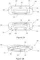
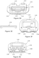
- Figure 2B is a perspective view from above, a lateral side and the anterior side of the inferior component 60.
- the superior and inferior components 40, 60 are the same as each other with the exception of the superior component having one aperture 42 therethrough and towards the anterior side whereas the inferior component has two apertures 62 therethrough, which are spaced apart from each other in the transverse direction and towards the anterior side.
- a perspective view of the inferior component 60 only of the superior and inferior components 40, 60 is therefore shown in the drawings.
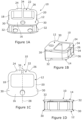
- the intervertebral fusion device of the first embodiment comprises a superior component 40, an inferior component 60 and a core component 10.
- Each of the superior component 40 and the inferior component 60 is generally of the form of a plate, albeit a plate having structures thereon and a large aperture through the centre thereof.
- the core component 10 has the form of a frustum of a wedge.
- the intervertebral fusion device is assembled by putting the superior and inferior components 40, 60 in the disposition shown in Figure 2A and then inserting the core component 10 between the superior and inferior components and such that the core component slidably inter-engages with the superior and inferior components, as is described further below.
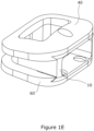
- the superior and inferior components 40, 60 are held to the core component 10 by inter-engagement, as shown in Figure 1E , with the core component determining the height of the intervertebral fusion device and the angle of the superior and inferior components relative to each other.
- Use of core components 10 of different thicknesses and/or different extents of tapering wedge and with the same superior component 40 and inferior component 60 provides for different heights and angles of intervertebral fusion device.
- the superior component 40 and the inferior component 60 are placed in the intervertebral space with the disposition shown generally in Figure 2A .
- the core component 10 is positioned relative to the superior and inferior components 40, 60 such that the thinner edge of the wedge shape of the core is foremost before the core component is progressively inserted between the superior and inferior components until fully received between the superior and inferior components.
- the superior component top side abuts against a first vertebra defining the intervertebral space in part and the inferior component bottom side abuts against a second vertebra defining the intervertebral space in part.
- Each keyway 72, 74 extends from adjacent an anterior side of the respective one of the superior and inferior components 40, 60 part way towards the posterior side and by a distance corresponding to the distance extended by the respective lateral protrusion 30, 32. Slidable reception of lateral protrusions 30, 32 in keyways 72, 74 hold the superior component 40, core component 10 and inferior component 60 together as the core component is slidably inserted between the superior and inferior components.
- Each keyway 72, 74 defines an inclined surface which extends from a distal edge of the part of the superior or inferior component defining the keyway in a transverse direction away from the distal edge.
- the inclined surfaces of the lateral protrusion 30, 32 and the keyway 72, 74 are of corresponding angle whereby the two inclined surfaces abut and allow for sliding movement of the core component 10 relative to the superior or inferior component 40, 60.
- the first and second keyways 72, 74 on each of the superior and inferior components 40, 60 taper in a direction from the posterior side to the anterior side. The angle of taper is the same as for the core component, i.e. 2.5 degrees to an anterior to posterior axis of the superior/inferior component.
- the inferior component 60 further defines a posterior recess 76 which extends between the first and second lateral sides 68, 70 near the posterior side.
- the posterior recess 76 has an inclined surface.
- the core component When the core component is being inserted between the superior and inferior components 40, 60, force is applied to the first lateral component 18 and the second lateral component 20 to bend the first and second lateral components towards each other, as described above, to put the core component in the contracted condition.
- Such compressive force is applied by the leading ends of the first and second lateral components 18, 20 bearing against the formations of the superior and inferior components that define the first and second keyways 72, 74 as the core component is inserted.
- the core component In the contracted condition, the core component can be slidably received between the superior and inferior components 40, 60 with lateral protrusions 30, 32 received in keyways 72, 74 as described above.
- the spring bias of the first and second lateral components 18, 20 releases the energy stored by the applied force and causes the first and second lateral components to spring apart and back to the expanded condition.
- the tapered lateral protrusions 30, 32 on the core component 10 bear against the tapered first and second keyways 72, 74 and such that they oppose each other to a small extent in the posterior-anterior direction to thereby present resistance to movement of the core component relative to the respective one of the superior and inferior components in a direction opposite to the direction of insertion of the core component between the superior and inferior components.
- the distal edges of the posterior protrusions 34, 36 ride up the inclined surfaces of their respective posterior recesses 76 to draw the superior component 40 down onto the core component and to draw the inferior component 60 up to the core component.
- a wedge or screw (not shown) is driven between the gap between the distal ends of the first and second posterior components 24, 26 to keep the core component in the expanded condition.
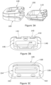
- the superior component 140 of this form of intervertebral fusion device is shown in Figure 3B and the inferior component 160 of this form of intervertebral fusion device is shown in Figure 3C .
- the superior and inferior components 140, 160 of this form of intervertebral fusion device are of the same form as the superior and inferior components 40, 60 of the first embodiment except as will now be described.
- the superior component 140 defines two anterior inter-engaging recesses 142 spaced apart along the anterior side.
- the superior component 140 also defines a posterior inter-engaging recess 144 towards the posterior side.
- the superior component 140 defines first 146 and second 148 retention mechanism recesses.
- the first retention mechanism recess 146 is towards a first lateral side of the superior component 140 and the second retention mechanism recess 148 is towards a second lateral side of the superior component with the first and second retention mechanism recesses facing each other in the transverse direction.
- the core component 110 has parallel sides and the superior and inferior components 140, 160 are correspondingly configured.
- the inferior component 160 defines two lateral channels 162. One of the two lateral channels 162 is towards the first lateral side and the other of the two lateral channels 162 is towards the second lateral side, with the two lateral channels facing each other in the transverse direction. Each of the two lateral channels 162 is open at the anterior side and extends towards the posterior side.
- the inferior component 160 also defines third 164 and fourth 166 retention mechanism recesses.
- the third retention mechanism recess 164 is towards a first lateral side of the inferior component 160 and the fourth retention mechanism recess 166 is towards a second lateral side of the inferior component with the third and fourth retention mechanism recesses facing each other in the transverse direction.
- Each of the third and fourth retention mechanism recesses 164, 166 is defined by the part of the inferior component 160 that defines the upper side of the lateral channel whereby the retention mechanism recesses 164, 166 is above the lateral channel.
- the core component 110 of this form (not claimed) of intervertebral fusion device is of the same form as the core component 10 of the first embodiment except as will now be described.
- the core component 110 of this form of intervertebral fusion device comprises two anterior inter-engaging protrusions 112 spaced apart along the anterior side.
- the core component 110 also defines first and second posterior inter-engaging protrusions 114, 115 towards the posterior side.
- the first posterior inter-engaging protrusion 114 inter-engages with the posterior inter-engaging recess 144 on the superior component
- the second posterior inter-engaging protrusion 115 inter-engages with a posterior inter-engaging recess 168 on the inferior component
- the two anterior inter-engaging protrusions 112 inter-engage respectively with the two anterior inter-engaging recesses 142 on the superior component to pull the superior component down onto the core component.
- the core component 110 further defines two elongate protrusions 116.
- the retention mechanism comprises a straight sprung member 170 formed of the like of MP35N.
- the sprung member 170 is mounted on the core component such that it extends in the transverse direction.
- a first end of the sprung member extends through a slot in the core component such that it protrudes beyond the periphery of the core component at the first lateral side and a second, opposite end of the sprung member extends through a slot in the core component such that it protrudes beyond the periphery of the core component at the second lateral side.
- the height of the sprung member 170 between the upper and lower sides of the core component and the supporting of the sprung member by the core component are such that the first and second ends of the sprung member face both the superior and inferior components.
- the first and second ends of the sprung member are withdrawn through their respective slots whereby neither of the first and second ends protrudes beyond the periphery of the core component at its respective lateral side.
- the retention mechanism is in its expanded condition when the sprung member 170 is unbent as shown in Figure 3D and the retention mechanism is in its contracted condition when the sprung member 170 is bent as shown in Figure 3F .
- the present form has a shaped sprung member 270 formed of MP35N instead of the straight sprung member 170 of the previous form of intervertebral fusion device.
- Figure 4 shows the shaped sprung member 270 to the right-hand side of the assembled intervertebral fusion device 200 and in its form when removed from the core component 210.
- the shaped sprung member 270 is mounted in the core component such that it is in the same shaped condition as shown in Figure 4 . This constitutes the contracted condition in which the core component 210 can be inserted between and brought into inter-engagement with the superior and inferior components 240, 260.
- a bending force is applied to the shaped sprung member 270 which causes the shaped sprung member to lengthen. Lengthening of the shaped sprung member 270 causes first and second opposite ends of the shaped sprung member to slide through slots in the core component 210 whereby the first and second ends of the shaped sprung member protrude beyond the periphery of the core component at the first and second lateral sides.
- the first and second ends of the shaped sprung member 170 protrude in this fashion and as shown in the assembled intervertebral fusion device 200 shown in Figure 4 , they are received in respective retention mechanism recesses in the superior and inferior components 240, 260.
- Reception of the first and second ends of the shaped sprung member 170 in retention mechanism recesses presents resistance to movement of the core component 210 from between the superior and inferior components 240, 260 in the same manner as for the previous form of intervertebral fusion device.
- the shaped sprung member 270 is in a bowed condition.
- the shaped sprung member 270 is structured and supported in the core component 210 such that the shaped sprung member 270 is distorted by the applied bending force to the extent that it has the shown bowed condition.
- a bending force needs to be applied in the opposite direction to the above described first applied bending force to return the shaped sprung member 270 to its original and contracted condition.
- the need for application of force to change the shaped sprung member 270 from its bowed to its original condition keeps the retention mechanism formed by way of the shaped sprung member 270 in the expanded condition.
- intervertebral fusion device 300 (not claimed) is shown in Figures 5A and 5B .
- This form of intervertebral fusion device 300 is of the same form and function as the intervertebral fusion device 100 of Figure 3A except as is described below.
- the present form of intervertebral fusion device 300 comprises a core component 310, a superior component 340 and an inferior component 360. Inter-engagement of the core component 310 with the superior and inferior components 340, 360 is by way of structure common with the intervertebral fusion device 100 of Figure 3A .
- the present form of intervertebral fusion device 300 is brought into use in the same fashion as the first embodiment and the intervertebral fusion device 100 of Figure 3A . The reader's attention is therefore directed to the description provided above for the intervertebral fusion device 100 of Figure 3A in respect of such common form and function and to the description provided above for the first embodiment in respect of use.
- the retention mechanism of this form 300 comprises a screw 312 (which constitutes a driving device).
- the screw 312 defines a first frustroconical surface 314 and a first threaded portion 316.
- the retention mechanism of this form of intervertebral fusion device 300 also comprises first 318 and second 320 retention mechanism portions. Each of the first and second retention mechanism portions 318, 320 is mounted towards the posterior end of the core component 310 for rotation on the core component.
- the first retention mechanism portion 318 defines a first part of a second frustroconical surface and the second retention mechanism portion 320 defines a second part of the second frustroconical surface.
- the first and second retention mechanism portions 318, 320 are located such that the first and second parts of the second frustroconical surface oppose each other.
- the first and second parts of the second frustroconical surface together define the second frustroconical surface, albeit with a gap between the first and second retention mechanism portions.
- the screw 312 When the core component 310 is fully received between the superior and inferior components 340, 360, the screw 312 is brought into use.
- the screw 312 is inserted through an aperture at the anterior side of the core component and then positioned such that the first threaded portion 316 is received between the first and second retention mechanism portions 318, 320 in the space defined by the second frustroconical surface.
- the screw 312 Upon further insertion, the screw 312 is received through an aperture defined by the first and second retention mechanism portions 318, 320 at the base of the second frustroconical surface and then threadedly engages with a second threaded portion (not evident from Figures 5A and 5B ) defined by part of the core component which is located closer to the posterior side of the core component than the first and second retention mechanism portions.
- Rotation of the screw 312 therefore causes the screw 312 to move linearly in relation to the first and second retention mechanism portions 318, 320 and towards the posterior end. Movement of the screw 312 towards the posterior end causes the first frustroconical surface 314 of the screw to push against the second frustroconical surface defined by the first and second retention mechanism portions 318, 320. Pushing of the first frustroconical surface 314 of the screw against the second frustroconical surface pushes the first and second retention mechanism portions 318, 320 apart.
Landscapes
- Health & Medical Sciences (AREA)
- Engineering & Computer Science (AREA)
- Biomedical Technology (AREA)
- Neurology (AREA)
- Orthopedic Medicine & Surgery (AREA)
- Cardiology (AREA)
- Oral & Maxillofacial Surgery (AREA)
- Transplantation (AREA)
- Heart & Thoracic Surgery (AREA)
- Vascular Medicine (AREA)
- Life Sciences & Earth Sciences (AREA)
- Animal Behavior & Ethology (AREA)
- General Health & Medical Sciences (AREA)
- Public Health (AREA)
- Veterinary Medicine (AREA)
- Prostheses (AREA)
Claims (14)
- Eine Zwischenwirbelfusionsvorrichtung, die Folgendes beinhaltet:eine obere Komponente (40) mit einer oberen Komponentenoberseite (46) und einer oberen Komponentenunterseite (44), wobei die obere Komponente dazu ausgelegt ist, in einem Zwischenwirbelraum zwischen einem ersten und zweiten Wirbel aufgenommen zu werden, wodurch die obere Komponentenoberseite gegen den ersten Wirbel stößt;eine untere Komponente (60) mit einer unteren Komponentenoberseite (64) und einer unteren Komponentenunterseite (66), wobei die untere Komponente dazu ausgelegt ist, in dem Zwischenwirbelraum zwischen dem ersten und zweiten Wirbel aufgenommen zu werden, wodurch die untere Komponentenunterseite gegen den zweiten Wirbel stößt, wobei die obere Komponentenunterseite (44) und die untere Komponentenoberseite (64) einander gegenüberliegen, wenn die obere und untere Komponente in dem Zwischenwirbelraum aufgenommen werden; undeine Kernkomponente (10), die zum Einschieben zwischen der oberen und unteren Komponente (40, 60) ausgelegt ist, wodurch eine Trennung zwischen der oberen und unteren Komponente bestimmt wird,wobei die Kernkomponente (10) einen Rückhaltemechanismus beinhaltet, der sich zwischen dem zusammengezogenen und dem expandierten Zustand in der medial-lateralen Richtung bewegt, wodurch die Kernkomponente in der medial-lateralen Richtung eine größere Ausdehnung aufweist, wenn sie in dem expandierten Zustand ist, als wenn sie in dem zusammengezogenen Zustand ist, aufgrund der Bewegung des Rückhaltemechanismus, wobei die Kernkomponente zwischen der oberen und unteren Komponente (40, 60) eingeschoben werden kann, wenn der Rückhaltemechanismus in dem zusammengezogenen Zustand ist, und der Rückhaltemechanismus mit einem Oberflächenprofil kooperiert, das auf jeder von der oberen und unteren Komponente definiert ist, wenn er in dem expandierten Zustand ist, wodurch die Kernkomponente mit der oberen und unteren Komponente ineinandergreift, um Widerstand gegen eine Bewegung der Kernkomponente von zwischen der oberen und unteren Komponente in einer der Einschubrichtung entgegengesetzten Richtung zu bieten,wobei die Kernkomponente (10) in der medial-lateralen Richtung eine geringere Ausdehnung aufweist, wenn sie in dem zusammengezogenen Zustand ist, als wenn sie in dem expandierten Zustand ist, wodurch der Rückhaltemechanismus über die Oberflächenprofile hinweg bewegt werden kann, um das Einschieben der Kernkomponente zwischen der oberen und unteren Komponente (40, 60) zu erlauben,wobei die Kernkomponente (10) einstückig ausgebildet ist und der Rückhaltemechanismus einstückig mit der Kernkomponente ist, wodurch die Kernkomponente so strukturiert ist, dass sie als der Rückhaltemechanismus betriebsfähig ist, undwobei die Kernkomponente (10) so ausgelegt ist, dass sie in der medial-lateralen Richtung elastisch komprimierbar ist, wodurch sich die Kernkomponente unter Druckbeanspruchung von dem expandierten Zustand zu dem zusammengezogenen Zustand bewegt, wobeidie Kernkomponente (10) eine Hinterseite und eine Vorderseite aufweist, wobei die Hinter- und Vorderseite entgegengesetzt gerichtet sind und die Hinterseite zwischen der oberen und unteren Komponente (40, 60) vor der Vorderseite aufgenommen wird, wenn die Kernkomponente zwischen der oberen und unteren Komponente eingeschoben wird, und wobei die Kernkomponente (10) eine erste und zweite laterale Seite aufweist, die in entgegengesetzte Richtungen zeigen, wobei jede von der ersten und zweiten lateralen Seite in die medial-laterale Richtung zeigen, wobei die Kernkomponente so strukturiert ist, dass die erste und zweite laterale Seite auf der Vorderseite nicht zueinander hin komprimiert werden, wenn eine Druckkraft angewendet wird, und so, dass die erste und zweite laterale Seite auf der Hinterseite zueinander hin komprimiert werden, wenn die Druckkraft angewendet wird.
- Zwischenwirbelfusionsvorrichtung gemäß Anspruch 1, wobei die Kernkomponente (10) zwischen der ersten und zweiten lateralen Seite auf der Vorderseite eine im Wesentlichen starre Struktur aufweist und zwischen der ersten und zweiten lateralen Seite auf der Hinterseite eine elastisch nachgiebige Struktur aufweist.
- Zwischenwirbelfusionsvorrichtung gemäß Anspruch 2, wobei die Kernkomponente (10) eine starre vordere Komponente (16), eine erste laterale Komponente (18) und eine zweite laterale Komponente (20) beinhaltet, wobei die starre vordere Komponente die Vorderseite definiert und sich zwischen der ersten und zweiten lateralen Komponente erstreckt, die jeweils die erste und zweite laterale Seite definieren, und wobei die starre vordere Komponente, die erste laterale Komponente und die zweite laterale Komponente einstückig ausgebildet sind.
- Zwischenwirbelfusionsvorrichtung gemäß Anspruch 3, wobei die Kernkomponente (10) ferner eine hintere Struktur (22) beinhaltet, die die Hinterseite definiert, und die sich von jeder von der ersten und zweiten lateralen Komponente erstreckt, wobei die hintere Struktur (22) dazu ausgelegt ist, sich auf der Hinterseite der ersten und zweiten lateralen Komponente (18, 20) zusammen und auseinander zu bewegen, um somit Kompression und Expansion bereitzustellen.
- Zwischenwirbelfusionsvorrichtung gemäß Anspruch 4, wobei die hintere Struktur (22) eine erste hintere Komponente (24) und eine zweite hintere Komponente (26) beinhaltet, wobei die erste hintere Komponente einstückig mit der ersten lateralen Komponente (18) ausgebildet ist und die zweite hintere Komponente einstückig mit der zweiten lateralen Komponente (20) ausgebildet ist, und wobei das distale Ende der ersten hinteren Komponente und das distale Ende der zweiten hinteren Komponente einander gegenüberliegen und voneinander beabstandet sind, wenn sie in dem expandierten Zustand sind.
- Zwischenwirbelfusionsvorrichtung gemäß Anspruch 5, die ferner ein Rückhalteelement beinhaltet, das zwischen dem distalen Ende der ersten hinteren Komponente (24) und dem distalen Ende der zweiten hinteren Komponente (26) eingeschoben ist, wenn es in dem expandierten Zustand ist, wobei das Rückhalteelement, wenn es so eingeschoben ist, eine Trennung zwischen dem distalen Ende der ersten hinteren Komponente und dem distalen Ende der zweiten hinteren Komponente aufrechterhält.
- Zwischenwirbelfusionsvorrichtung gemäß Anspruch 5 oder 6, wobei jede von der ersten und zweiten lateralen Komponente (18, 20) dazu ausgelegt ist, sich elastisch zu biegen, wodurch sich die distalen Enden der ersten und zweiten hinteren Komponente (24, 26) aufeinander zubewegen.
- Zwischenwirbelfusionsvorrichtung gemäß einem der vorhergehenden Ansprüche, wobei eine Distanz zwischen der ersten und zweiten lateralen Seite auf der Hinterseite größer ist als eine Distanz zwischen der ersten und zweiten lateralen Seite auf der Vorderseite, wenn die Kernkomponente (10) in dem expandierten Zustand ist, wobei sich die Kernkomponente von der Hinterseite zu der Vorderseite verjüngt.
- Zwischenwirbelfusionsvorrichtung gemäß einem der vorhergehenden Ansprüche, wobei die Oberflächenprofile der Kernkomponente (10) gleitend in Eingriff mit den Oberflächenprofilen von jeder von der oberen und unteren Komponente (40, 60) kommen, um eine Barriere gegen die Bewegung der oberen und unteren Komponente weg von der Kernkomponente in eine Richtung der Wirbelsäulenachse darzustellen, während die Kernkomponente gleitend zwischen der oberen und unteren Komponente aufgenommen wird.
- Zwischenwirbelfusionsvorrichtung gemäß einem der vorhergehenden Ansprüche, wobei die Kernkomponente (10) ein erstes und zweites Paar von oberen und unteren lateralen Vorsprüngen (30, 32) beinhaltet, wobei das erste und zweite Paar von oberen und unteren lateralen Vorsprüngen jeweils von der ersten und zweiten lateralen Seite der Kernkomponente hervorragt, wobei die oberen und unteren lateralen Vorsprünge (30, 32) in jedem Paar in einer Richtung der Wirbelsäulenachse beabstandet sind, wobei sich jeder von den oberen und unteren lateralen Vorsprüngen entlang einer jeweiligen lateralen Seite in einer Richtung zwischen der Vorder- und Hinterseite erstreckt, und wobei jede von der oberen und unteren Komponente (40, 60) eine erste und zweite Keilnut (72, 74) definiert, wobei jede erste Keilnut (72) hin zu einer ersten lateralen Seite einer jeweiligen von der oberen und unteren Komponente und jede zweite Keilnut (74) hin zu einer zweiten lateralen Seite einer jeweiligen von der oberen und unteren Komponente liegt, wobei die erste und zweite Keilnut von jeder von der oberen und unteren Komponente einander gegenüberliegen, wobei sich jede von der ersten und zweiten Keilnut von einer Vorderseite einer jeweiligen von der oberen und unteren Komponente zu der Hinterseite der Komponente erstreckt, und jede Keilnut (72, 74) zum gleitenden Aufnehmen eines jeweiligen von den lateralen Vorsprüngen (30, 32) der Kernkomponente gestaltet ist.
- Zwischenwirbelfusionsvorrichtung gemäß Anspruch 10, wobei sich jeder laterale Vorsprung (30, 32) von der Nähe der Vorderseite der Kernkomponente (10) bis zu nicht mehr als der Hälfte des Weges hin zu der Hinterseite der Kernkomponente erstreckt, wodurch die Aufnahme der lateralen Vorsprünge in ihren jeweiligen Keilnuten (72, 74) die obere und untere Komponente (40, 60) an der Kernkomponente (10) auf der Vorderseite der Kernkomponente festhält.
- Zwischenwirbelfusionsvorrichtung gemäß Anspruch 10 oder 11, wobei jeder laterale Vorsprung (30, 32) eine geneigte Oberfläche definiert, die sich von einem distalen Ende des lateralen Vorsprungs hin zu der Kernkomponente (10) erstreckt, und jede Keilnut (72, 74) eine geneigte Oberfläche definiert, die sich von einem distalen Ende des Teils der oberen oder unteren Komponente (40, 60) erstreckt, die die Keilnut in einer Querrichtung weg von dem distalen Ende definiert, wobei die geneigten Oberflächen des lateralen Vorsprungs und der Keilnut einen entsprechenden Winkel aufweisen, wodurch die geneigten Oberflächen aneinander anstoßen und eine relative Gleitbewegung erlauben.
- Zwischenwirbelfusionsvorrichtung gemäß einem der Ansprüche 10 bis 12, wobei sich die erste und zweite Keilnut (72, 74) auf jeder von der oberen und unteren Komponente (40, 60) in einer Richtung von der Hinterseite zu der Vorderseite verjüngen, wodurch eine Distanz zwischen der ersten und zweiten Keilnut auf der Vorderseite geringer ist als hin zu der Hinterseite.
- Zwischenwirbelfusionsvorrichtung gemäß einem der vorhergehenden Ansprüche, wobei die obere Komponente (40), die untere Komponente (60) und die Kernkomponente (10) separate Komponenten sind, die obere Komponente und die untere Komponente außer durch die Kernkomponente nicht miteinander in Eingriff stehen.
Applications Claiming Priority (2)
| Application Number | Priority Date | Filing Date | Title |
|---|---|---|---|
| GB201913777A GB201913777D0 (en) | 2019-09-24 | 2019-09-24 | Intervertebral devices |
| PCT/GB2020/052317 WO2021058962A1 (en) | 2019-09-24 | 2020-09-24 | Intervertebral devices |
Publications (3)
| Publication Number | Publication Date |
|---|---|
| EP4034047A1 EP4034047A1 (de) | 2022-08-03 |
| EP4034047B1 true EP4034047B1 (de) | 2025-04-09 |
| EP4034047C0 EP4034047C0 (de) | 2025-04-09 |
Family
ID=68425567
Family Applications (1)
| Application Number | Title | Priority Date | Filing Date |
|---|---|---|---|
| EP20796879.3A Active EP4034047B1 (de) | 2019-09-24 | 2020-09-24 | Zwischenwirbelvorrichtungen |
Country Status (4)
| Country | Link |
|---|---|
| US (2) | US12029657B2 (de) |
| EP (1) | EP4034047B1 (de) |
| GB (1) | GB201913777D0 (de) |
| WO (1) | WO2021058962A1 (de) |
Family Cites Families (12)
| Publication number | Priority date | Publication date | Assignee | Title |
|---|---|---|---|---|
| US6045579A (en) | 1997-05-01 | 2000-04-04 | Spinal Concepts, Inc. | Adjustable height fusion device |
| US8308804B2 (en) | 2008-11-14 | 2012-11-13 | David Krueger | Spinal fusion device |
| US9526628B2 (en) | 2008-11-14 | 2016-12-27 | David Krueger | Spinal fusion device |
| US8465547B2 (en) * | 2010-01-27 | 2013-06-18 | Warsaw Orthopedic, Inc. | Modular interbody devices and methods of use |
| US9566168B2 (en) | 2010-09-03 | 2017-02-14 | Globus Medical, Inc. | Expandable fusion device and method of installation thereof |
| US8454700B2 (en) | 2011-10-04 | 2013-06-04 | Zimmer Spine, Inc. | Interbody vertebral spacer |
| US9498349B2 (en) | 2012-10-09 | 2016-11-22 | Titan Spine, Llc | Expandable spinal implant with expansion wedge and anchor |
| US9402738B2 (en) | 2013-02-14 | 2016-08-02 | Globus Medical, Inc. | Devices and methods for correcting vertebral misalignment |
| FR3020756B1 (fr) | 2014-05-06 | 2022-03-11 | Ldr Medical | Implant vertebral, dispositif de fixation vertebrale d'implant et instrumentation d'implantation |
| WO2016019241A1 (en) | 2014-08-01 | 2016-02-04 | H. Lee Moffitt Cancer Center And Research Institute, Inc. | Expandable intervertebral cage |
| KR101674491B1 (ko) | 2015-07-10 | 2016-11-09 | 주식회사 메드릭스 | 최소 침습 수술용 케이지 장치 |
| EP3742990B1 (de) | 2018-03-01 | 2026-02-11 | Integrity Implants Inc. | Expandierbare fusionsvorrichtung mit unabhängigen expansionssystemen |
-
2019
- 2019-09-24 GB GB201913777A patent/GB201913777D0/en not_active Ceased
-
2020
- 2020-09-24 EP EP20796879.3A patent/EP4034047B1/de active Active
- 2020-09-24 US US17/763,193 patent/US12029657B2/en active Active
- 2020-09-24 WO PCT/GB2020/052317 patent/WO2021058962A1/en not_active Ceased
-
2024
- 2024-07-08 US US18/766,011 patent/US20250073044A1/en active Pending
Also Published As
| Publication number | Publication date |
|---|---|
| US20220339003A1 (en) | 2022-10-27 |
| GB201913777D0 (en) | 2019-11-06 |
| WO2021058962A1 (en) | 2021-04-01 |
| EP4034047A1 (de) | 2022-08-03 |
| US12029657B2 (en) | 2024-07-09 |
| EP4034047C0 (de) | 2025-04-09 |
| US20250073044A1 (en) | 2025-03-06 |
Similar Documents
| Publication | Publication Date | Title |
|---|---|---|
| EP3761914B1 (de) | Zwischenwirbelkäfige mit integrierter erweiterung und winkelverstellmechanismus | |
| US12115082B2 (en) | Inter vertebral devices | |
| US9149364B2 (en) | Expandable interbody spacer device | |
| US10034769B2 (en) | Spinal implant device | |
| US8888854B2 (en) | Expandable fusion device and method of installation thereof | |
| US10010432B2 (en) | Intervertebral implants, systems, and methods of use | |
| US9155628B2 (en) | Expandable fusion device and method of installation thereof | |
| EP3883503B1 (de) | Zwischenwirbelimplantat | |
| US20260041565A1 (en) | Intervertebral devices | |
| EP2732797B1 (de) | Interkorporelles Fusionsimplantat | |
| US11654030B2 (en) | Standalone anterior lumber interbody spacer | |
| AU2009252835A1 (en) | Intersomatic cage | |
| US12310860B2 (en) | Expandable fusion device and method of installation thereof | |
| EP4034047B1 (de) | Zwischenwirbelvorrichtungen | |
| US20250312171A1 (en) | Intervertebral devices | |
| EP4103110B1 (de) | Zwischenwirbelvorrichtungen | |
| US20230038323A1 (en) | Intervertebral devices | |
| US20250186217A1 (en) | Intervertebral devices |
Legal Events
| Date | Code | Title | Description |
|---|---|---|---|
| STAA | Information on the status of an ep patent application or granted ep patent |
Free format text: STATUS: UNKNOWN |
|
| STAA | Information on the status of an ep patent application or granted ep patent |
Free format text: STATUS: THE INTERNATIONAL PUBLICATION HAS BEEN MADE |
|
| PUAI | Public reference made under article 153(3) epc to a published international application that has entered the european phase |
Free format text: ORIGINAL CODE: 0009012 |
|
| STAA | Information on the status of an ep patent application or granted ep patent |
Free format text: STATUS: REQUEST FOR EXAMINATION WAS MADE |
|
| 17P | Request for examination filed |
Effective date: 20220330 |
|
| AK | Designated contracting states |
Kind code of ref document: A1 Designated state(s): AL AT BE BG CH CY CZ DE DK EE ES FI FR GB GR HR HU IE IS IT LI LT LU LV MC MK MT NL NO PL PT RO RS SE SI SK SM TR |
|
| DAV | Request for validation of the european patent (deleted) | ||
| DAX | Request for extension of the european patent (deleted) | ||
| GRAP | Despatch of communication of intention to grant a patent |
Free format text: ORIGINAL CODE: EPIDOSNIGR1 |
|
| STAA | Information on the status of an ep patent application or granted ep patent |
Free format text: STATUS: GRANT OF PATENT IS INTENDED |
|
| INTG | Intention to grant announced |
Effective date: 20241113 |
|
| GRAS | Grant fee paid |
Free format text: ORIGINAL CODE: EPIDOSNIGR3 |
|
| GRAA | (expected) grant |
Free format text: ORIGINAL CODE: 0009210 |
|
| STAA | Information on the status of an ep patent application or granted ep patent |
Free format text: STATUS: THE PATENT HAS BEEN GRANTED |
|
| AK | Designated contracting states |
Kind code of ref document: B1 Designated state(s): AL AT BE BG CH CY CZ DE DK EE ES FI FR GB GR HR HU IE IS IT LI LT LU LV MC MK MT NL NO PL PT RO RS SE SI SK SM TR |
|
| RAP3 | Party data changed (applicant data changed or rights of an application transferred) |
Owner name: AXIS SPINE TECHNOLOGIES LTD |
|
| REG | Reference to a national code |
Ref country code: GB Ref legal event code: FG4D |
|
| RIN1 | Information on inventor provided before grant (corrected) |
Inventor name: POWELL, DAVID Inventor name: SANDHAM, NICHOLAS Inventor name: REAH, CHRISTOPHER Inventor name: ARCOS, JONATHAN |
|
| REG | Reference to a national code |
Ref country code: CH Ref legal event code: EP |
|
| REG | Reference to a national code |
Ref country code: DE Ref legal event code: R096 Ref document number: 602020049190 Country of ref document: DE |
|
| REG | Reference to a national code |
Ref country code: IE Ref legal event code: FG4D |
|
| U01 | Request for unitary effect filed |
Effective date: 20250426 |
|
| U07 | Unitary effect registered |
Designated state(s): AT BE BG DE DK EE FI FR IT LT LU LV MT NL PT RO SE SI Effective date: 20250502 |
|
| REG | Reference to a national code |
Ref country code: CH Ref legal event code: U11 Free format text: ST27 STATUS EVENT CODE: U-0-0-U10-U11 (AS PROVIDED BY THE NATIONAL OFFICE) Effective date: 20251001 |
|
| PG25 | Lapsed in a contracting state [announced via postgrant information from national office to epo] |
Ref country code: ES Free format text: LAPSE BECAUSE OF FAILURE TO SUBMIT A TRANSLATION OF THE DESCRIPTION OR TO PAY THE FEE WITHIN THE PRESCRIBED TIME-LIMIT Effective date: 20250409 |
|
| PG25 | Lapsed in a contracting state [announced via postgrant information from national office to epo] |
Ref country code: NO Free format text: LAPSE BECAUSE OF FAILURE TO SUBMIT A TRANSLATION OF THE DESCRIPTION OR TO PAY THE FEE WITHIN THE PRESCRIBED TIME-LIMIT Effective date: 20250709 Ref country code: GR Free format text: LAPSE BECAUSE OF FAILURE TO SUBMIT A TRANSLATION OF THE DESCRIPTION OR TO PAY THE FEE WITHIN THE PRESCRIBED TIME-LIMIT Effective date: 20250710 |
|
| PG25 | Lapsed in a contracting state [announced via postgrant information from national office to epo] |
Ref country code: PL Free format text: LAPSE BECAUSE OF FAILURE TO SUBMIT A TRANSLATION OF THE DESCRIPTION OR TO PAY THE FEE WITHIN THE PRESCRIBED TIME-LIMIT Effective date: 20250409 |
|
| PGFP | Annual fee paid to national office [announced via postgrant information from national office to epo] |
Ref country code: GB Payment date: 20250912 Year of fee payment: 6 |
|
| PG25 | Lapsed in a contracting state [announced via postgrant information from national office to epo] |
Ref country code: HR Free format text: LAPSE BECAUSE OF FAILURE TO SUBMIT A TRANSLATION OF THE DESCRIPTION OR TO PAY THE FEE WITHIN THE PRESCRIBED TIME-LIMIT Effective date: 20250409 |
|
| PG25 | Lapsed in a contracting state [announced via postgrant information from national office to epo] |
Ref country code: RS Free format text: LAPSE BECAUSE OF FAILURE TO SUBMIT A TRANSLATION OF THE DESCRIPTION OR TO PAY THE FEE WITHIN THE PRESCRIBED TIME-LIMIT Effective date: 20250709 |
|
| U20 | Renewal fee for the european patent with unitary effect paid |
Year of fee payment: 6 Effective date: 20250917 |
|
| PG25 | Lapsed in a contracting state [announced via postgrant information from national office to epo] |
Ref country code: IS Free format text: LAPSE BECAUSE OF FAILURE TO SUBMIT A TRANSLATION OF THE DESCRIPTION OR TO PAY THE FEE WITHIN THE PRESCRIBED TIME-LIMIT Effective date: 20250809 |
|
| PG25 | Lapsed in a contracting state [announced via postgrant information from national office to epo] |
Ref country code: SM Free format text: LAPSE BECAUSE OF FAILURE TO SUBMIT A TRANSLATION OF THE DESCRIPTION OR TO PAY THE FEE WITHIN THE PRESCRIBED TIME-LIMIT Effective date: 20250409 |
|
| PGFP | Annual fee paid to national office [announced via postgrant information from national office to epo] |
Ref country code: CH Payment date: 20251001 Year of fee payment: 6 |
|
| PG25 | Lapsed in a contracting state [announced via postgrant information from national office to epo] |
Ref country code: CZ Free format text: LAPSE BECAUSE OF FAILURE TO SUBMIT A TRANSLATION OF THE DESCRIPTION OR TO PAY THE FEE WITHIN THE PRESCRIBED TIME-LIMIT Effective date: 20250409 |
|
| PG25 | Lapsed in a contracting state [announced via postgrant information from national office to epo] |
Ref country code: SK Free format text: LAPSE BECAUSE OF FAILURE TO SUBMIT A TRANSLATION OF THE DESCRIPTION OR TO PAY THE FEE WITHIN THE PRESCRIBED TIME-LIMIT Effective date: 20250409 |
|
| PLBE | No opposition filed within time limit |
Free format text: ORIGINAL CODE: 0009261 |
|
| STAA | Information on the status of an ep patent application or granted ep patent |
Free format text: STATUS: NO OPPOSITION FILED WITHIN TIME LIMIT |
|
| REG | Reference to a national code |
Ref country code: CH Ref legal event code: L10 Free format text: ST27 STATUS EVENT CODE: U-0-0-L10-L00 (AS PROVIDED BY THE NATIONAL OFFICE) Effective date: 20260218 |
|
| 26N | No opposition filed |
Effective date: 20260112 |