EP4034003B1 - Einstellbare schnittstellenvorrichtung zum verbinden von komponenten eines medizinprodukts - Google Patents
Einstellbare schnittstellenvorrichtung zum verbinden von komponenten eines medizinprodukts Download PDFInfo
- Publication number
- EP4034003B1 EP4034003B1 EP19783891.5A EP19783891A EP4034003B1 EP 4034003 B1 EP4034003 B1 EP 4034003B1 EP 19783891 A EP19783891 A EP 19783891A EP 4034003 B1 EP4034003 B1 EP 4034003B1
- Authority
- EP
- European Patent Office
- Prior art keywords
- elongate
- interface device
- elongate body
- catheter
- adjustable interface
- Prior art date
- Legal status (The legal status is an assumption and is not a legal conclusion. Google has not performed a legal analysis and makes no representation as to the accuracy of the status listed.)
- Active
Links
Images


Classifications
-
- A—HUMAN NECESSITIES
- A61—MEDICAL OR VETERINARY SCIENCE; HYGIENE
- A61B—DIAGNOSIS; SURGERY; IDENTIFICATION
- A61B17/00—Surgical instruments, devices or methods
- A61B17/22—Implements for squeezing-off ulcers or the like on inner organs of the body; Implements for scraping-out cavities of body organs, e.g. bones; for invasive removal or destruction of calculus using mechanical vibrations; for removing obstructions in blood vessels, not otherwise provided for
- A61B17/22004—Implements for squeezing-off ulcers or the like on inner organs of the body; Implements for scraping-out cavities of body organs, e.g. bones; for invasive removal or destruction of calculus using mechanical vibrations; for removing obstructions in blood vessels, not otherwise provided for using mechanical vibrations, e.g. ultrasonic shock waves
- A61B17/22012—Implements for squeezing-off ulcers or the like on inner organs of the body; Implements for scraping-out cavities of body organs, e.g. bones; for invasive removal or destruction of calculus using mechanical vibrations; for removing obstructions in blood vessels, not otherwise provided for using mechanical vibrations, e.g. ultrasonic shock waves in direct contact with, or very close to, the obstruction or concrement
-
- A—HUMAN NECESSITIES
- A61—MEDICAL OR VETERINARY SCIENCE; HYGIENE
- A61B—DIAGNOSIS; SURGERY; IDENTIFICATION
- A61B17/00—Surgical instruments, devices or methods
- A61B2017/00477—Coupling
-
- A—HUMAN NECESSITIES
- A61—MEDICAL OR VETERINARY SCIENCE; HYGIENE
- A61B—DIAGNOSIS; SURGERY; IDENTIFICATION
- A61B17/00—Surgical instruments, devices or methods
- A61B17/22—Implements for squeezing-off ulcers or the like on inner organs of the body; Implements for scraping-out cavities of body organs, e.g. bones; for invasive removal or destruction of calculus using mechanical vibrations; for removing obstructions in blood vessels, not otherwise provided for
- A61B17/22004—Implements for squeezing-off ulcers or the like on inner organs of the body; Implements for scraping-out cavities of body organs, e.g. bones; for invasive removal or destruction of calculus using mechanical vibrations; for removing obstructions in blood vessels, not otherwise provided for using mechanical vibrations, e.g. ultrasonic shock waves
- A61B17/22012—Implements for squeezing-off ulcers or the like on inner organs of the body; Implements for scraping-out cavities of body organs, e.g. bones; for invasive removal or destruction of calculus using mechanical vibrations; for removing obstructions in blood vessels, not otherwise provided for using mechanical vibrations, e.g. ultrasonic shock waves in direct contact with, or very close to, the obstruction or concrement
- A61B2017/22014—Implements for squeezing-off ulcers or the like on inner organs of the body; Implements for scraping-out cavities of body organs, e.g. bones; for invasive removal or destruction of calculus using mechanical vibrations; for removing obstructions in blood vessels, not otherwise provided for using mechanical vibrations, e.g. ultrasonic shock waves in direct contact with, or very close to, the obstruction or concrement the ultrasound transducer being outside patient's body; with an ultrasound transmission member; with a wave guide; with a vibrated guide wire
- A61B2017/22015—Implements for squeezing-off ulcers or the like on inner organs of the body; Implements for scraping-out cavities of body organs, e.g. bones; for invasive removal or destruction of calculus using mechanical vibrations; for removing obstructions in blood vessels, not otherwise provided for using mechanical vibrations, e.g. ultrasonic shock waves in direct contact with, or very close to, the obstruction or concrement the ultrasound transducer being outside patient's body; with an ultrasound transmission member; with a wave guide; with a vibrated guide wire with details of the transmission member
- A61B2017/22018—Implements for squeezing-off ulcers or the like on inner organs of the body; Implements for scraping-out cavities of body organs, e.g. bones; for invasive removal or destruction of calculus using mechanical vibrations; for removing obstructions in blood vessels, not otherwise provided for using mechanical vibrations, e.g. ultrasonic shock waves in direct contact with, or very close to, the obstruction or concrement the ultrasound transducer being outside patient's body; with an ultrasound transmission member; with a wave guide; with a vibrated guide wire with details of the transmission member segmented along its length
-
- A—HUMAN NECESSITIES
- A61—MEDICAL OR VETERINARY SCIENCE; HYGIENE
- A61B—DIAGNOSIS; SURGERY; IDENTIFICATION
- A61B90/00—Instruments, implements or accessories specially adapted for surgery or diagnosis and not covered by any of the groups A61B1/00 - A61B50/00, e.g. for luxation treatment or for protecting wound edges
- A61B90/06—Measuring instruments not otherwise provided for
- A61B2090/061—Measuring instruments not otherwise provided for for measuring dimensions, e.g. length
-
- A—HUMAN NECESSITIES
- A61—MEDICAL OR VETERINARY SCIENCE; HYGIENE
- A61B—DIAGNOSIS; SURGERY; IDENTIFICATION
- A61B90/00—Instruments, implements or accessories specially adapted for surgery or diagnosis and not covered by any of the groups A61B1/00 - A61B50/00, e.g. for luxation treatment or for protecting wound edges
- A61B90/08—Accessories or related features not otherwise provided for
- A61B2090/0807—Indication means
- A61B2090/0811—Indication means for the position of a particular part of an instrument with respect to the rest of the instrument, e.g. position of the anvil of a stapling instrument
Definitions
- the present invention relates to a medical device, and, more particularly, to an adjustable interface device for connecting components of a medical device.
- Medical devices may be used to perform surgical procedures, such as for example, a vascular occlusion crossing procedure or an atherectomy procedure, so as to restore patency and blood flow that was lost due to one or more intravascular occlusions.
- One type of medical device is an ultrasonic device configured to perform the vascular occlusion crossing procedure and/or the atherectomy procedure.
- a crossing procedure is a procedure in which an opening is formed through the intravascular occlusion.
- An atherectomy procedure may include crossing, but also attempts to break up and remove the intravascular occlusion.
- the ultrasonic device may include an ultrasonic catheter and a support catheter for performing the procedures.
- an adjustable interface device that may be interposed between, and connected to, two components of a medical device, wherein the adjustable interface device has an adjustable length.
- WO 2012/096816 A1 discloses objects and features that may be generally noted in catheter systems to simplify and ease access to one or more target anatomies in various medical procedures, thereby reducing procedure time and associated costs.
- JP 2014 057746 A discloses a medical instrument which allows an operator to confirm the projecting state of an outer cylinder and an inner cylinder at hand of the operator.
- the medical instrument disclosed includes: an outer needle; an inner cylinder inserted into the outer needle; and a treatment implement inserted into the inner cylinder.
- the outer needle is movable between a first position where the tip is projected from the forward end of the inner cylinder and a second position where the tip is retreated from the forward end of the inner cylinder.
- the base end part of the inner cylinder is provided with a projection member projected in the radial direction and a turning member for the outer cylinder, which is supported on the projection member so as to be freely turnable and can come close to and separate from the outer peripheral surface of the outer needle.
- the base end part of the outer needle is provided with an engaging member which can be engaged with the turning member for the outer cylinder.
- the turning member for the outer cylinder includes: a first engagement part for holding the outer needle in the first position by engagement with the engaging member ; and a second engagement part for holding the outer needle in the second position by engagement with the engaging member.
- US 5 423 846 A discloses a Dottering Auger Catheter system designed for penetration of tight stenoses or total occlusions (called blockages) as a precursor to balloon angioplasty, atherectomy, or any other vessel opening means that requires an initial passageway.
- the Dottering Auger Catheter system consists of a centering catheter and a Dottering auger catheter which is a catheter that opens a passageway through an arterial blockage by passing its wedge shaped distal end through that blockage causing outward plastic deformation of the plaque; i.e., angioplasty.
- a centering catheter that surrounds the Dottering Auger Catheter can be used to center the distal end of the auger catheter just proximal to the blockage.
- the purpose of the auger type of Dottering catheter is to penetrate through the blockage by means of a self-tapping screw at the catheter's distal end. Once the first thread of the screw is pushed into the blockage, rotation of the catheter resulting from turning a handle at the catheter's proximal end will cause the screw to pull itself through the blockage while a push force on the handle is also applied.
- the auger catheter Once the auger has Dottered a passageway through the blockage, the auger catheter is removed and replaced with a guide wire. Once the guide wire is in place through the newly opened passageway, the centering catheter is removed and conventional balloon angioplasty or atherectomy can be performed to further enlarge the hole through the blockage thus restoring adequate blood flow.
- the present invention provides an adjustable interface device that may be interposed between, and connected to, two components of a medical device, wherein the adjustable interface device has an adjustable length.
- the invention in one form, is directed to an adjustable interface device for connecting two components of a medical device for an occlusion crossing or atherectomy procedure.
- the adjustable interface device includes an elongate body,an elongate member and an adapter.
- the elongate body has a first end, a second end, an interior channel, and a side wall that surrounds the interior channel.
- the interior channel is configured to extend between the first end and the second end.
- the elongate body has a longitudinal axis that longitudinally extends through the interior channel.
- the side wall is configured to define a first connector portion adjacent the second end.
- the first connector portion has an annular recess and is configured to attach to a respective one of the two components of the medical device.
- the elongate member has a head end portion and a shaft portion that longitudinally extends from the head end portion.
- the shaft portion is located at least partially in the interior channel of the elongate body.
- the shaft portion is configured to slidably move axially along the longitudinal axis to adjust a length of the adjustable interface device.
- the head end portion defines a second connector portion configured to attach to the other of the two components of the medical device.
- the adapter has a threaded end portion and a snap-fit end portion.
- the snap-fit end portion has an annular protrusion configured for engagement with the annular recess of the connector portion of the elongate body.
- the invention in another form is directed to an ultrasonic device that includes a handpiece, a support catheter and an adjustable interface device.
- the handpiece includes a handpiece housing, and an ultrasonic catheter connected to the handpiece housing.
- the handpiece housing is configured with an outer shape and size to facilitate being grasped by an operator.
- the ultrasonic catheter has a first mounting portion.
- the support catheter has a catheter body and a catheter sheath connected to the catheter body.
- the catheter body has a second mounting portion.
- the catheter sheath has a distal end.
- the adjustable interface device includes an elongate body,an elongate member and an adapter, according to the device described above.
- adjustable interface device may be used, for example, to selectively and easily adapt the ultrasonic device for use in each of a crossing procedure and an atherectomy procedure.
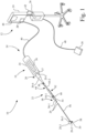
- a medical system 10 in accordance with an embodiment of the present invention, which may be used for performing a medical procedure, such as an occlusion crossing and/or an atherectomy procedure.
- medical system 10 may include a console 12 and a medical device, such as for example, an ultrasonic device 14.
- ultrasonic device 14 includes a handpiece 16, a support catheter 18, and an ultrasonic catheter 20.
- Support catheter 18 is detachably attached to handpiece 16 by an adjustable interface device 22, in accordance with an aspect of the present invention.
- console 12 includes a user interface 24, a controller 26, and an ultrasonic energy source 28 located in user interface 24.
- Console 12 may include multiple components in separate housing units, as in the embodiment shown, or may include the multiple components in a single housing unit.
- console 12 also may include a foot switch 30.
- handpiece 16 includes a handpiece housing 34 and an ultrasonic transducer 36 mounted internally to handpiece housing 34.
- Ultrasonic catheter 20 is mechanically connected to ultrasonic transducer 36, and to handpiece housing 34.
- Handpiece housing 34 has an outer shape and size to facilitate being grasped by an operator during a crossing or atherectomy procedure.
- Handpiece housing 34 includes at its distal end a mounting portion 37 configured to facilitate connection to ultrasonic catheter 20.
- Ultrasonic transducer 36 may be, for example, a piezoelectric-type transducer. Ultrasonic transducer 36 of handpiece 16 is electrically connected to ultrasonic energy source 28 by an electrical cable 40. Ultrasonic transducer 36 is configured to receive and convert the ultrasonic electrical excitation signals generated by ultrasonic energy source 28 into ultrasonic vibrational energy, which may be in a frequency range corresponding to that of the ultrasonic electrical excitation signal generated by ultrasonic energy source 28.
- User interface 24 of console 12 is connected to controller 26 via an electrical cable 42, e.g., a multi-wire cable or USB, to provide electrical and communication interconnection.
- user interface 24 may be a wireless link, e.g., Bluetooth, which is communicatively coupled to controller 26.
- User interface 24 may include, for example, a touchscreen display 44 and associated input and output processing circuitry.
- Touchscreen display 44 may include, for example, a liquid crystal display (LCD) or a light-emitting diode (LED) display.
- user interface 24 may be in the form of a laptop computer or tablet.
- User interface 24 is configured to generate control signals based on user input received by touchscreen display 44. For example, a user may operate touchscreen display 44 of user interface 24 to provide the control signals to controller 26 to initiate and/or terminate operation of ultrasonic energy source 28.
- Controller 26 is electrically connected and communicatively coupled to each of user interface 24 and ultrasonic energy source 28.
- Controller 26 may include, for example, processor circuitry, interface circuitry, and electronic memory circuitry.
- Controller 26 is configured, for example, to execute program instructions to process signals received from touchscreen display 44 of user interface 24, and to execute program instructions to provide output control signals to ultrasonic energy source 28 to control the operation of ultrasonic energy source 28, such as for example, to control the frequency and/or electrical output power, of the ultrasonic electrical excitation signal generated by ultrasonic energy source 28.
- Ultrasonic energy source 28 is connected to ultrasonic transducer 36via an electrical cable 40. Ultrasonic energy source 28 generates the ultrasonic electrical excitation signal that is delivered to ultrasonic transducer 36.
- the frequency of the ultrasonic electrical excitation signal may be selectable, and or variable, in a range of 20 kHz to 40 kHz, for example. In some applications, for example, the ultrasonic frequency of the ultrasonic electrical excitation signal may be, or may initially be, at a frequency of 20 kHz.
- Foot switch 30 is connected to controller 26 via an electrical cable 48. Foot switch 30 may provide auxiliary input signals to controller 26, which in turn controller 26 may use to activate and deactivate system components, e.g., ultrasonic energy source 28 of medical system 10.
- controller 26 may use to activate and deactivate system components, e.g., ultrasonic energy source 28 of medical system 10.
- support catheter 18 includes a catheter body 54, a catheter sheath 56, and a catheter lumen 58.
- Catheter sheath 56 is connected to catheter body 54.
- Catheter lumen 58 extends through an entirety of catheter body 54 and catheter sheath 56.
- catheter body 54 and catheter sheath 56 may be formed as an integral unit, wherein a proximal end 56-1 catheter sheath 56 is permanently connected to catheter body 54.
- Catheter body 54 has a proximal end 54-1 that defines a proximal end of support catheter 18.
- Catheter body 54 also includes, at proximal end 54-1, a mounting portion 60 to facilitate connection to adjustable interface device 22.
- Catheter sheath 56 of support catheter 18 may be in the form of an elongate flexible tube, such as a polymer tube.
- Catheter sheath 56 of support catheter 18 includes proximal end 56-1 and a distal end 56-2, and includes a portion of catheter lumen 58.
- Distal end 56-2 of catheter sheath 56 defines a distal end of support catheter 18.
- catheter lumen 58 is an elongate lumen that longitudinally extends through both of catheter body 54 and catheter sheath 56, to distal end 56-2 of catheter sheath 56, and may be formed as a central lumen, relative to the diameter, of catheter sheath 56.
- ultrasonic catheter 20 is an elongate member that includes a sheath that surrounds a flexible metal wire, e.g., nitinol.
- the sheath of ultrasonic catheter 20 is located in, and longitudinally extends within, catheter lumen 58 of catheter sheath 56 of support catheter 18.
- ultrasonic catheter 20 may have a length greater than 60 centimeters (cm), and in some embodiments, for example, a length of 100 cm to 200 cm.
- Ultrasonic catheter 20 has a proximal end 20-1, a distal tip 20-2, a distal end portion 20-3, and a handpiece 20-4, wherein the sheath of ultrasonic catheter 20 longitudinally extends from handpiece 20-4.
- Proximal end 20-1 of ultrasonic catheter 20 is operably connected to ultrasonic transducer 36, e.g., by a sonic connector, to receive the vibrational energy from ultrasonic transducer 36 so as to produce a vibrational motion of at least distal tip 20-2 of ultrasonic catheter 20.
- the vibrational motion of ultrasonic catheter 20 may be longitudinal or a combination of longitudinal and transverse vibration.
- Distal tip 20-2 of ultrasonic catheter 20 may be, for example, a blunt tip, e.g., a rounded tip, that is not pointed.
- catheter sheath 56 of support catheter 18 and ultrasonic catheter 20 are advanced into a blood vessel of the vasculature having a vascular occlusion, wherein distal tip 20-2 of ultrasonic catheter 20 engages the vascular occlusion.
- Distal end portion 20-3 is the portion of ultrasonic catheter 20 that extends proximally from distal tip 20-2 of ultrasonic catheter 20, and distal end portion 20-3 distally terminates at distal tip 20-2.
- Handpiece 20-4 of ultrasonic catheter 20 includes a mounting portion 38 to facilitate connection to adjustable interface device 22.
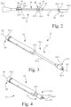
- Adjustable interface device 22 connects support catheter 18 to handpiece housing 34 of handpiece 16.
- adjustable interface device 22 is set to an intermediate length.
- Fig. 3 shows adjustable interface device 22 in a fully extended position 22-1
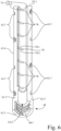
- Fig. 4 shows adjustable interface device 22 in a fully retracted position 22-2.
- a length of adjustable interface device 22 is adjustable between the fully extended position 22-1 and the fully retracted position 22-2 to accommodate both crossing and atherectomy procedures.
- an adjustment of a length of adjustable interface device 22 in turn adjusts a position of distal end 56-2 of catheter sheath 56 relative to the distal tip 20-2 of ultrasonic catheter 20, so as to adjust an amount of distal end portion 20-3 of ultrasonic catheter 20 that extends distally from distal end 56-2 of catheter sheath 56.
- distal end portion 20-3 of ultrasonic catheter 20 may be wholly disposed within the catheter lumen 58 of catheter sheath 56.
- distal tip 20-2 of ultrasonic catheter 20 will extend a maximum distance, e.g., 10 centimeters (cm), from distal end 56-2 of catheter sheath 56, such that the entirety of distal end portion 20-3 of ultrasonic catheter 20 is exposed beyond distal end 56-2 of catheter sheath 56 of support catheter 18.
- adjustable interface device 22 provides more support to distal tip 20-2 of ultrasonic catheter 20 when extended, and adjustable interface device 22 provides more freedom to advance distal tip 20-2 of ultrasonic catheter 20 relative to support catheter 18 when retracted. Also, adjustable interface device 22 provides a general benefit of moving both support catheter 18 and ultrasonic catheter 20 as a unit during a procedure.
- adjustable interface device 22 includes an elongate body 62 and an elongate member 64.
- elongate member 64 is slidably and rotationally disposed in elongate body 62.
- a length of adjustable interface device 22 is adjusted by longitudinally sliding elongate member 64 relative to elongate body 62.
- the length of adjustable interface device 22 may be locked by rotating elongate member 64 relative to elongate body 62, e.g., by a one-sixteenth to one-quarter turn of rotation of elongate member 64 relative to elongate body 62.
- Elongate body 62 includes a first end 62-1, a second end 62-2, a side wall 62-3, and an interior channel 62-4.
- Side wall 62-3 radially surrounds interior channel 62-4.
- Interior channel 62-4 extends between first end 62-1 and second end 62-2 of elongate body 62.
- Elongate body 62 has a longitudinal axis 66 that longitudinally extends through interior channel 62-4.
- Side wall 62-3 is configured to define a first connector portion 68 adjacent the second end 62-2.
- First connector portion 68 of elongate body 62 is configured to attach to a respective one of mounting portion 38 of handpiece 20-4 of ultrasonic catheter 20 or mounting portion 60 of support catheter 18, depending on an orientation of adjustable interface device 22 relative to handpiece 20-4 of ultrasonic catheter 20 and support catheter 18.
- elongate body 62 is configured as a split housing having a pair of separable housing portions, namely, housing portion 62-5 and housing portion 62-6, wherein housing portion 62-5 and housing portion 62-6 are connected together by sets of longitudinally spaced hook-latch members 62-7.
- first connector portion 68 of elongate body 62 is configured to attach to mounting portion 60 of the support catheter 18. Also, referring to Figs. 5 and 6 , in the present embodiment, first connector portion 68 of elongate body 62 and mounting portion 60 of the support catheter 18 is configured to form a screw-type coupling, e.g., a Luer connection.
- first connector portion 68 of elongate body 62 may be configured as a female threaded portion 68-1 and mounting portion 60 of the support catheter 18 may be configured as a male threaded portion, or vice-versa.
- Figs. 7 and 8 show an interference, e.g., snap fit, connection as an alternative to the configuration of the embodiment depicted in Figs. 5 and 6 that depict the screw-type coupling, e.g., a Luer connection, for connecting first connector portion 68 of elongate body 62 to mounting portion 60 of the support catheter 18.
- Figs. 7 and 8 show that first connector portion 68 of elongate body 62 may be configured as a female portion having an annular recess 68-2.
- mounting portion 60 of the support catheter 18 may be configured as a corresponding male portion having an annular protrusion.
- first connector portion 68 of elongate body 62 is moved longitudinally relative to mounting portion 60 of the support catheter 18 such that the annular recess 68-2 of first connector portion 68 of elongate body 62 is engaged by the annular protrusion of mounting portion 60 of the support catheter 18 so as to establish the snap fit (and rotatable) connection of support catheter 18 to adjustable interface device 22.
- Adapter 69 includes a body 69-1 having a threaded end portion 69-2 and a snap-fit end portion 69-3. Snap-fit end portion 69-3 includes an annular protrusion 69-4. Annular protrusion 69-4 is configured for engagement with annular recess 68-2 of first connector portion 68 of elongate body 62.
- the use of adapter 69 facilitates connection of the embodiment of body 62 depicted in Figs. 7 and 8 to a threaded connector, while facilitating full rotation of adapter 69, and therefore, also facilitating full rotation of support catheter 18.
- elongate member 64 includes a head end portion 64-1 and a shaft portion 64-2.
- Shaft portion 64-2 longitudinally extends from head end portion 64-1.
- Shaft portion 64-2 is located in interior channel 62-4 of the elongate body 62.
- Shaft portion 64-2 is configured to slidably move axially along the longitudinal axis 66 to adjust a length of the adjustable interface device 22.
- Head end portion 64-1 defines a second connector portion 70 that is configured to attach to a respective one of mounting portion 38 of handpiece 20-4 of ultrasonic catheter 20 and mounting portion 60 of support catheter 18, depending on an orientation of adjustable interface device 22 relative to handpiece 16 and support catheter 18.
- second connector portion 70 of elongate member 64 is configured to attach to mounting portion 38 of handpiece 20-4 of ultrasonic catheter 20. Also, in the present embodiment, second connector portion 70 of elongate member 64 and mounting portion 38 of handpiece 20-4 of ultrasonic catheter 20 are configured to form an interference fit, e.g., via a snap-type coupling.
- second connector portion 70 of elongate member 64 may be configured as a female portion having an annular recess
- mounting portion 38 of handpiece 20-4 of ultrasonic catheter 20 may be configured as a male portion having an annular protrusion
- second connector portion 70 of elongate member 64 is moved longitudinally relative to mounting portion 38 of handpiece 20-4 of ultrasonic catheter 20 such that the annular recess of second connector portion 70 of elongate member 64 is engaged by the annular protrusion of mounting portion 38 of handpiece 20-4 of ultrasonic catheter 20 so as to establish the snap fit connection of handpiece housing 34 to adjustable interface device 22.
- elongate member 64 includes an elongate passage 64-3 that is in communication with the interior channel 62-4 of the elongate body 62.
- Elongate passage 64-3 of elongate member 64 and interior channel 62-4 of the elongate body 62 are configured to receive ultrasonic catheter 20 that is supported by the support catheter 18, wherein ultrasonic catheter 20 longitudinally extends from handpiece 16 through each of elongate passage 64-3 of elongate member 64, interior channel 62-4 of elongate body 62, and catheter lumen 58 of support catheter 18.
- shaft portion 64-2 of elongate member 64 may include a plurality of length indicators 72 longitudinally spaced along the shaft portion 64-2.
- the plurality of length indicators 72 are configured to indicate a distance associated with the length of adjustable interface device 22.
- the plurality of length indicators 72 may be, for example, in the form of etched or painted bands, and may further include numerical length indicators, if desired.
- adjustable interface device 22 further includes a locking mechanism 74 configured to lock a longitudinal position of elongate member 64 relative to elongate body 62, after the length of the adjustable interface device 22 is set by a user to a desired length.
- locking mechanism 74 includes interior channel 62-4 of elongate body 62 and shaft portion 64-2 of the elongate member 64, as further describe below.
- Interior channel 62-4 of the elongate body 62 includes a longitudinal track 76 and a plurality of arcuate tracks 78 that are formed in side wall 62-3 of elongate body 62.
- Longitudinal track 76 and the plurality of arcuate tracks 78 form the elongate body 62 portion of locking mechanism 74.
- the plurality of arcuate tracks 78 are longitudinally spaced along longitudinal track 76 and circumferentially intersect the longitudinal track 76, wherein each arcuate track of the plurality of arcuate tracks 78 is a branch extension of the longitudinal track 76.
- the plurality of arcuate tracks 78 of the interior channel 62-4 of elongate body 62 define a plurality of discrete increments (e.g., 2.0 cm increments) of adjustment of the length of adjustable interface device 22.
- longitudinal track 76 of interior channel 62-4 of elongate body 62 includes a pair of diametrically opposed longitudinal track sections 76-1, 76-2, and each of the pair of diametrically opposed longitudinal track sections 76-1, 76-2 includes a respective plurality of complimentary arcuate track extensions formed by a respective portion of the plurality of arcuate tracks 78. Notwithstanding, it is contemplated that longitudinal track 76 may be formed by a single longitudinal track section, or multiple longitudinal track sections.
- Shaft portion 64-2 of the elongate member 64 has an outer surface 64-4 and a tail end portion 64-5.
- Tail end portion 64-5 includes an engagement member 80 that extends radially outwardly from the outer surface 64-4.
- engagement member 80 includes a pair of diametrically opposed tabs 80-1, 80-2 that respectively slidably engage longitudinal track sections 76-1, 76-2. While in the present embodiment, engagement member 80 includes a pair of diametrically opposed tabs 80-1, 80-2, it is contemplated that engagement member 80 may be formed by a single tab, if desired.
- engagement member 80 engages and slides along longitudinal track 76 to facilitate longitudinal movement of elongate member 64 relative to elongate body 62 of adjustable interface device 22, so as to adjust a length of adjustable interface device 22.
- engagement member 80 is configured to be rotatably received into a selected one of the plurality of arcuate tracks 78 of elongate body 62 so as to lock the longitudinal position of the elongate member 64 relative to the elongate body 62.
- elongate member 64 and elongate body 62 of adjustable interface device 22 are longitudinally positioned such that engagement member 80 is radially aligned with one of the plurality of arcuate tracks 78, then a rotation of elongate member 64 relative to elongate body 62 causes engagement member 80 to depart from longitudinal track 76 and enter the respective arcuate track of the plurality of arcuate tracks 78 of elongate body 62, thereby impeding longitudinal movement of elongate member 64 and elongate body 62.
- each arcuate track of the plurality of arcuate tracks 78 may include a pair of tapered walls 78-1, 78-2.
- the pair of tapered walls 78-1, 78-2 is configured such that when engagement member 80 is rotatably received into a selected one of the plurality of arcuate tracks 78, engagement member 80 of elongate member 64 is wedged between the pair of tapered walls 78-1, 78-2 so as to maintain both the rotational and longitudinal position of elongate member 64 relative to the elongate body 62, and further to impede both rotational and longitudinal movement of the elongate member 64 relative to the elongate body 62, as well as to allow for selection of length.
- Figs. 9 and 10 depict an alternative embodiment for a locking mechanism, in the form of a locking mechanism 100. It is contemplated that locking mechanism 100 may serve as a supplemental locking mechanism to that of locking mechanism 74, or may serve as a replacement for locking mechanism 74, if desired.
- Locking mechanism 100 includes a pivot member 102, locking lever 104, and a stow clip 106.
- Pivot member 102 is connected to the elongate body 62. Pivot member 102 defines a pivot axis 108.
- Locking lever 104 has a pivot end 104-1 and a locking end 104-2.
- locking end 104-2 of locking lever 104 has a U-shaped yoke 104-3 configured to clip over shaft portion 64-2 of the elongate member 64 in a snug fit, at a location adjacent, e.g., proximal, to head end portion 64-1 of elongate member 64.
- Pivot end 104-1 of locking lever 104 is rotatably connected to pivot member 102 of elongate body 62 by a pivot joint 110 located at pivot axis 108.
- Pivot joint 110 may be, for example, a pin-hole arrangement.
- Locking lever 104 is configured to pivot at pivot joint 110 of pivot member 102 between a stowed position 112 as shown in Fig. 9 and a locking position 114 shown in Fig. 10 .
- locking lever 104 In stowed position 112, shown in Fig. 9 , locking lever 104 is disengaged from shaft portion 64-2 of elongate member 64, such that elongate member 64 may move longitudinally relative to elongate body 62. Locking lever 104 is stowed by rotating locking lever 104 about pivot axis 108 until locking lever 104 engages stow clip 106.
- U-shaped yoke 104-3 of locking end 104-2 of locking lever 104 is engaged with, i.e., clips to, shaft portion 64-2 of the elongate member 64 adjacent to head end portion 64-1 of elongate member 64, thereby preventing a shortening of adjustable interface device 22.
- elongate member 64 is lengthened relative to elongate body 62, and locking lever 104 is rotated about pivot axis 108 until U-shaped yoke 104-3 of locking end 104-2 of locking lever 104 engages, i.e., clips, to shaft portion 64-2 of the elongate member 64 adjacent to head end portion 64-1 of elongate member 64.
- adjustable interface device 22 has been described above with respect to a medical system having an ultrasonic device with a particular configuration as an example of use, those skilled in the art will recognize that the adjustable interface device 22 may be adapted for use in other types of medical devices, including other types of ultrasonic devices, wherein a spacing between two medical components is to be controllably adjusted.
Landscapes
- Health & Medical Sciences (AREA)
- Surgery (AREA)
- Engineering & Computer Science (AREA)
- Life Sciences & Earth Sciences (AREA)
- Biomedical Technology (AREA)
- Molecular Biology (AREA)
- Vascular Medicine (AREA)
- Orthopedic Medicine & Surgery (AREA)
- Mechanical Engineering (AREA)
- Heart & Thoracic Surgery (AREA)
- Medical Informatics (AREA)
- Nuclear Medicine, Radiotherapy & Molecular Imaging (AREA)
- Animal Behavior & Ethology (AREA)
- General Health & Medical Sciences (AREA)
- Public Health (AREA)
- Veterinary Medicine (AREA)
- Surgical Instruments (AREA)
- Ultra Sonic Daignosis Equipment (AREA)
- Media Introduction/Drainage Providing Device (AREA)
Claims (15)
- Einstellbare Schnittstellenvorrichtung (22) zum Verbinden von zwei Komponenten einer medizinischen Vorrichtung für eine Okklusionskreuzung oder eine Atherektomieprozedur, umfassend:einen länglichen Körper (62), aufweisend ein erstes Ende (62-1), ein zweites Ende (62-2), einen Innenkanal (62-4) und eine Seitenwand (62-3), die den Innenkanal umgibt, wobei der Innenkanal so konfiguriert ist, dass er sich zwischen dem ersten Ende und dem zweiten Ende erstreckt, wobei der längliche Körper eine Längsachse (66) aufweist, die sich in Längsrichtung durch den Innenkanal erstreckt, wobei die Seitenwand so konfiguriert ist, dass sie benachbart zu dem zweiten Ende einen ersten Verbindungsabschnitt (68) definiert, wobei der erste Verbindungsabschnitt eine ringförmige Aussparung (68-2) aufweist, wobei der erste Verbindungsabschnitt so konfiguriert ist, dass er an einer jeweiligen der beiden Komponenten der medizinischen Vorrichtung anbringbar ist;ein längliches Element (64), aufweisend einen vorderen Endabschnitt (64-1) und einem Schaftabschnitt (64-2), der sich in Längsrichtung vom vorderen Endabschnitt erstreckt, wobei der Schaftabschnitt sich zumindest teilweise im Innenkanal des länglichen Körpers befindet, wobei der Schaftabschnitt so konfiguriert ist, dass er sich axial entlang der Längsachse gleitend bewegt, um eine Länge der einstellbaren Schnittstellenvorrichtung einzustellen, wobei der vordere Endabschnitt einen zweiten Verbindungsabschnitt definiert, der so konfiguriert ist, dass er an der anderen der beiden Komponenten der medizinischen Vorrichtung anbringbar ist; undeinen Adapter (69), aufweisend einen Gewindeendabschnitt (69-2) und einen Schnappverschlussendabschnitt (69-3), wobei der Schnappverschlussendabschnitt einen ringförmigen Vorsprung (69-4) aufweist, der zum Eingriff mit der ringförmigen Aussparung des ersten Verbindungsabschnitts des länglichen Körpers konfiguriert ist.
- Einstellbare Schnittstellenvorrichtung (22) nach Anspruch 1, wobei das längliche Element (64) einen länglichen Durchgang (64-3) einschließt, der mit dem Innenkanal (62-4) des länglichen Körpers (62) in Verbindung steht.
- Einstellbare Schnittstellenvorrichtung (22) nach einem der Ansprüche 1 bis 2, umfassend eine Vielzahl von Längenindikatoren (72), die in Längsrichtung entlang des Schaftabschnitts (64-2) beabstandet sind, wobei die Vielzahl von Längenindikatoren so konfiguriert ist, dass sie einen mit der Länge der einstellbaren Schnittstellenvorrichtung verknüpften Abstand angibt.
- Einstellbare Schnittstellenvorrichtung (22) nach einem der Ansprüche 1 bis 3, umfassend einen Verriegelungsmechanismus (74, 100), der so konfiguriert ist, dass er eine Längsposition des länglichen Elements (64) relativ zum länglichen Körper (62) verriegelt, nachdem die Länge der einstellbaren Schnittstellenvorrichtung auf eine gewünschte Länge gesetzt ist.
- Einstellbare Schnittstellenvorrichtung (22) nach Anspruch 4, wobei der Verriegelungsmechanismus (74) ein erstes Eingriffselement (80) am Schaftabschnitt (64-2) und ein zweites Eingriffselement (78) am Innenkanal (62-4) einschließt, wobei das erste Eingriffselement so konfiguriert ist, dass es in vordefinierten Intervallen entlang der Längsachse (66) des Innenkanals mit dem zweiten Eingriffselement in Eingriff kommt.
- Einstellbare Schnittstellenvorrichtung (22) nach Anspruch 4, wobei der Verriegelungsmechanismus (74) den Innenkanal (62-4) des länglichen Körpers (62) und den Schaftabschnitt (64-2) des länglichen Elements (64) einschließt, und wobei:der Innenkanal (62-4) des länglichen Körpers eine Längsschiene (76) und eine Vielzahl von bogenförmigen Schienen (78) umfasst, die in der Seitenwand (62-3) des länglichen Körpers gebildet sind, wobei die Vielzahl von bogenförmigen Schienen entlang der Längsschiene in Längsrichtung beabstandet sind und die Längsschiene in Umfangsrichtung schneiden, wobei jede bogenförmige Schiene der Vielzahl von bogenförmigen Schienen eine Verzweigungserstreckung der Längsschiene ist; undder Schaftabschnitt des länglichen Elements eine Außenfläche (64-4) und einen hinteren Endabschnitt (64-5) aufweist, wobei der hintere Endabschnitt ein Eingriffselement (80) aufweist, das sich von der Außenfläche radial nach außen erstreckt, wobei das Eingriffselement so konfiguriert ist, dass es entlang der Längsschiene gleitet, und wobei das Eingriffselement so konfiguriert ist, dass es drehbar in einer ausgewählten der Vielzahl von bogenförmigen Schienen aufgenommen wird, um die Längsposition des länglichen Elements relativ zum länglichen Körper zu verriegeln.
- Einstellbare Schnittstellenvorrichtung (22) nach Anspruch 6, wobei die Vielzahl von bogenförmigen Schienen (78) des Innenkanals des länglichen Körpers eine Vielzahl von diskreten Einstellungsschrittgrößen der Länge der einstellbaren Schnittstellenvorrichtung definiert.
- Einstellbare Schnittstellenvorrichtung (22) nach einem der Ansprüche 6 bis 7, wobei jede bogenförmige Schiene (78) der Vielzahl von bogenförmigen Schienen ein Paar von sich verjüngenden Wänden (78-1, 78-2) aufweist, wobei das Paar von sich verjüngenden Wänden so konfiguriert ist, dass, wenn das Eingriffselement (80) drehbar in der ausgewählten der Vielzahl von bogenförmigen Schienen aufgenommen ist, das Eingriffselement des länglichen Elements (64) zwischen dem Paar von sich verjüngenden Wänden eingeklemmt ist, um sowohl eine Dreh- als auch eine Längsbewegung des länglichen Elements relativ zu dem länglichen Körper (62) zu verhindern.
- Einstellbare Schnittstellenvorrichtung (22) nach einem der Ansprüche 6 bis 8, wobei:die Längsschiene (76) des Innenkanals (62-4) des länglichen Körpers (62) ein Paar von diametral gegenüberliegenden Längsschienenabschnitten (76-1, 76-2) umfasst und jeder von dem Paar von diametral gegenüberliegenden Längsschienenabschnitten eine Vielzahl von bogenförmigen Schienenverlängerungen einschließt, die durch einen jeweiligen Abschnitt der Vielzahl von bogenförmigen Schienen (78) gebildet sind; unddas Eingriffselement (80) des länglichen Elements (64) ein Paar von diametral gegenüberliegenden Eingriffslaschen (80-1, 80-2) umfasst, wobei das Paar von diametral gegenüberliegenden Eingriffslaschen in die diametral gegenüberliegenden Längsschienenabschnitte eingreift.
- Einstellbare Schnittstellenvorrichtung (22) nach Anspruch 4, wobei der Verriegelungsmechanismus (100) umfasst:ein Schwenkelement (102), das mit dem länglichen Körper (62) verbunden ist,einen Verriegelungshebel (104), aufweisend ein Schwenkende (104-1) und ein Verriegelungsende (104-2), wobei das Schwenkende so konfiguriert ist, dass es drehbar mit dem Schwenkelement des länglichen Körpers verbunden ist, wobei der Verriegelungshebel so konfiguriert ist, dass er am Schwenkelement zwischen einer verstauten Position (112) und einer Verriegelungsposition (114) schwenken kann, wobei in der Verriegelungsposition das Verriegelungsende des Verriegelungshebels mit dem Schaftabschnitt (64-2) des länglichen Elements (64) in Eingriff steht.
- Einstellbare Schnittstellenvorrichtung (22) nach Anspruch 10, wobei das Verriegelungsende (104-2) des Verriegelungshebels (104) ein U-förmiges Joch (104-3) aufweist, das so konfiguriert ist, dass es an einer Stelle proximal zum vorderen Endabschnitt (64-1) des länglichen Elements (64) in einer engen Passung über den Schaftabschnitt (64-2) des länglichen Elements klemmbar ist.
- Ultraschallvorrichtung (14), umfassend:ein Handstück (16), das ein Handstückgehäuse (34) und einen mit dem Handstückgehäuse verbundenen Ultraschallkatheter (20) einschließt, wobei das Handstückgehäuse mit einer äußeren Form und Größe konfiguriert ist, die das Ergreifen durch einen Bediener erleichtern, wobei der Ultraschallkatheter einen ersten Montageabschnitt (37) aufweist;einen Stützkatheter (18), aufweisend einen Katheterkörper (54) und eine Katheterhülle (56), die mit dem Katheterkörper verbunden ist, wobei der Katheterkörper einen zweiten Montageabschnitt aufweist, wobei die Katheterhülle ein distales Ende (56-2) aufweist; undeine einstellbare Schnittstellenvorrichtung (22) nach einem der vorstehenden Ansprüche.
- Ultraschallvorrichtung (14) nach Anspruch 12, wobei das längliche Element (64) einen länglichen Durchgang (64-3) einschließt, der mit dem Innenkanal (62-4) des länglichen Körpers (62) in Verbindung steht, wobei der längliche Durchgang und der Innenkanal so konfiguriert sind, dass sie ein Ultraschallübertragungselement (20) aufnehmen, das vom Stützkatheter (18) gestützt ist.
- Ultraschallvorrichtung nach Anspruch 13 in Abhängigkeit von Anspruch 12 und einem der Ansprüche 4 bis 11, wobei der Verriegelungsmechanismus den Innenkanal (62-4) des länglichen Körpers (62) und den Schaftabschnitt (64-2) des länglichen Elements (64) einschließt, und wobei:der Innenkanal (62-4) des länglichen Körpers eine Längsschiene (76) und eine Vielzahl von bogenförmigen Schienen (78) umfasst, die in der Seitenwand (62-3) des länglichen Körpers gebildet sind, wobei die Vielzahl von bogenförmigen Schienen entlang der Längsschiene in Längsrichtung beabstandet sind und die Längsschiene in Umfangsrichtung schneiden, wobei jede bogenförmige Schiene der Vielzahl von bogenförmigen Schienen eine Verzweigungserstreckung der Längsschiene ist; undder Schaftabschnitt (64-2) des länglichen Elements eine Außenfläche (64-4) und einen hinteren Endabschnitt (64-5) aufweist, wobei der hintere Endabschnitt ein Eingriffselement (80) aufweist, das sich von der Außenfläche radial nach außen erstreckt, wobei das Eingriffselement so konfiguriert ist, dass es entlang der Längsschiene gleitet, und wobei das Eingriffselement so konfiguriert ist, dass es drehbar in einer ausgewählten der Vielzahl von bogenförmigen Schienen aufgenommen wird, um die Längsposition des länglichen Elements relativ zum länglichen Körper zu verriegeln.
- Ultraschallvorrichtung nach Anspruch 14, wobei die Vielzahl von bogenförmigen Schienen (78) des Innenkanals des länglichen Körpers (62) eine Vielzahl von diskreten Einstellungsschrittgrößen der Länge der einstellbaren Schnittstellenvorrichtung definiert.
Applications Claiming Priority (1)
| Application Number | Priority Date | Filing Date | Title |
|---|---|---|---|
| PCT/US2019/052936 WO2021061119A1 (en) | 2019-09-25 | 2019-09-25 | Adjustable interface device for connecting components of a medical device |
Publications (3)
| Publication Number | Publication Date |
|---|---|
| EP4034003A1 EP4034003A1 (de) | 2022-08-03 |
| EP4034003B1 true EP4034003B1 (de) | 2024-10-30 |
| EP4034003C0 EP4034003C0 (de) | 2024-10-30 |
Family
ID=68165831
Family Applications (1)
| Application Number | Title | Priority Date | Filing Date |
|---|---|---|---|
| EP19783891.5A Active EP4034003B1 (de) | 2019-09-25 | 2019-09-25 | Einstellbare schnittstellenvorrichtung zum verbinden von komponenten eines medizinprodukts |
Country Status (5)
| Country | Link |
|---|---|
| US (1) | US12274461B2 (de) |
| EP (1) | EP4034003B1 (de) |
| JP (1) | JP7425865B2 (de) |
| CN (1) | CN114449962A (de) |
| WO (1) | WO2021061119A1 (de) |
Families Citing this family (1)
| Publication number | Priority date | Publication date | Assignee | Title |
|---|---|---|---|---|
| US20240123210A1 (en) * | 2022-10-18 | 2024-04-18 | Biosense Webster (Israel) Ltd. | Catheter insertion tool |
Family Cites Families (22)
| Publication number | Priority date | Publication date | Assignee | Title |
|---|---|---|---|---|
| US4417890A (en) * | 1981-08-17 | 1983-11-29 | Baxter Travenol Laboratories, Inc. | Antibacterial closure |
| US5423846A (en) | 1991-10-21 | 1995-06-13 | Cathco, Inc. | Dottering auger catheter system |
| US5466222A (en) | 1994-03-30 | 1995-11-14 | Scimed Life Systems, Inc. | Longitudinally collapsible and exchangeable catheter |
| US6613017B1 (en) | 2000-08-08 | 2003-09-02 | Scimed Life Systems, Inc. | Controlled depth injection device and method |
| ATE536198T1 (de) | 2001-10-18 | 2011-12-15 | Abbeymoor Medical Inc | Endourethrale vorrichtung |
| US20040143240A1 (en) | 2003-01-17 | 2004-07-22 | Armstrong Joseph R. | Adjustable length catheter |
| CA2687282A1 (en) | 2007-05-18 | 2008-11-27 | The Mclean Hospital Corporation | Apparatus and method for convection enhanced therapeutic delivery |
| US8147480B2 (en) | 2007-09-28 | 2012-04-03 | Codman & Shurtleff, Inc. | Catheter for reduced reflux in targeted tissue delivery of a therapeutic agent |
| US8454579B2 (en) * | 2009-03-25 | 2013-06-04 | Icu Medical, Inc. | Medical connector with automatic valves and volume regulator |
| EP2453813B1 (de) | 2009-07-15 | 2017-07-05 | Ethicon LLC | Elektrochirurgisches Ultraschallinstrument |
| RU2565389C2 (ru) | 2009-11-26 | 2015-10-20 | Колопласт А/С | Раздвижное устройство |
| US20140018732A1 (en) * | 2011-01-10 | 2014-01-16 | Spotlight Technology Partners Llc | Apparatus and Methods for Accessing and Treating a Body Cavity, Lumen, or Ostium |
| US20140228874A1 (en) | 2011-09-09 | 2014-08-14 | Spine Wave, Inc. | Apparatus for dilating bodily tissue and for monitoring neural activity in the dilated bodily tissue |
| US10213556B2 (en) * | 2011-12-08 | 2019-02-26 | Unl Holdings Llc | Accurate dose control mechanisms and drug delivery syringes |
| US9821141B2 (en) | 2012-07-26 | 2017-11-21 | Twin Star Medical, Inc. | Macroporous catheter |
| JP6071361B2 (ja) * | 2012-09-18 | 2017-02-01 | 株式会社トップ | 医療器具 |
| WO2014164515A1 (en) | 2013-03-13 | 2014-10-09 | The Regents Of The University Of California | Catheter with a rotation capability |
| US9517324B2 (en) | 2013-03-15 | 2016-12-13 | The Board Of Trustees Of The University Of Illinois | Extendable intravenous catheter |
| US10758264B2 (en) * | 2014-11-13 | 2020-09-01 | The Regents Of The University Of California | Adjustable stepped cannula |
| US10682503B2 (en) | 2015-06-30 | 2020-06-16 | Sanovas Intellectual Property, Llc | Sinus ostia dilation system |
| CN108135591B (zh) | 2016-02-24 | 2021-05-28 | 禾木(中国)生物工程有限公司 | 柔性增强的神经血管导管 |
| US10736649B2 (en) | 2016-08-25 | 2020-08-11 | Ethicon Llc | Electrical and thermal connections for ultrasonic transducer |
-
2019
- 2019-09-25 EP EP19783891.5A patent/EP4034003B1/de active Active
- 2019-09-25 JP JP2022518715A patent/JP7425865B2/ja active Active
- 2019-09-25 CN CN201980100788.4A patent/CN114449962A/zh active Pending
- 2019-09-25 US US17/761,636 patent/US12274461B2/en active Active
- 2019-09-25 WO PCT/US2019/052936 patent/WO2021061119A1/en not_active Ceased
Also Published As
| Publication number | Publication date |
|---|---|
| JP7425865B2 (ja) | 2024-01-31 |
| EP4034003A1 (de) | 2022-08-03 |
| US12274461B2 (en) | 2025-04-15 |
| US20220330963A1 (en) | 2022-10-20 |
| CN114449962A (zh) | 2022-05-06 |
| EP4034003C0 (de) | 2024-10-30 |
| JP2023501872A (ja) | 2023-01-20 |
| WO2021061119A1 (en) | 2021-04-01 |
Similar Documents
| Publication | Publication Date | Title |
|---|---|---|
| US6599304B1 (en) | Methods and apparatus for treating vascular occlusions | |
| US5908395A (en) | Vibrating guidewire | |
| US6217549B1 (en) | Methods and apparatus for treating vascular occlusions | |
| US20220071647A1 (en) | Vascular Re-Entry Device | |
| US8435228B2 (en) | Interventional catheter assemblies incorporating guide wire brake and management systems | |
| US9108027B2 (en) | Interventional catheter housing assemblies incorporating guide wire brakes and management systems | |
| US5910105A (en) | Control handle for an endoscope | |
| JPH0640875B2 (ja) | アセレクトミー装置 | |
| US20080312671A1 (en) | Infusion flow guidewire system | |
| US20170143372A1 (en) | Improved atherectomy device | |
| JP2000245741A (ja) | サイドバルーンを備えた回転式アテレクトミーシステム | |
| JP2001087275A (ja) | サイドバルーンを備えた回転式アテレクトミーシステム | |
| CA2343050A1 (en) | Methods and apparatus for treating vascular occlusions | |
| EP4034003B1 (de) | Einstellbare schnittstellenvorrichtung zum verbinden von komponenten eines medizinprodukts | |
| WO2008157077A1 (en) | Forwardly directable fluid jet crossing catheter | |
| US6475225B1 (en) | Ablation assembly with elastomeric driveshaft connection | |
| WO2025166320A1 (en) | Handheld oscillating wire torque device |
Legal Events
| Date | Code | Title | Description |
|---|---|---|---|
| STAA | Information on the status of an ep patent application or granted ep patent |
Free format text: STATUS: UNKNOWN |
|
| STAA | Information on the status of an ep patent application or granted ep patent |
Free format text: STATUS: THE INTERNATIONAL PUBLICATION HAS BEEN MADE |
|
| PUAI | Public reference made under article 153(3) epc to a published international application that has entered the european phase |
Free format text: ORIGINAL CODE: 0009012 |
|
| STAA | Information on the status of an ep patent application or granted ep patent |
Free format text: STATUS: REQUEST FOR EXAMINATION WAS MADE |
|
| 17P | Request for examination filed |
Effective date: 20220420 |
|
| AK | Designated contracting states |
Kind code of ref document: A1 Designated state(s): AL AT BE BG CH CY CZ DE DK EE ES FI FR GB GR HR HU IE IS IT LI LT LU LV MC MK MT NL NO PL PT RO RS SE SI SK SM TR |
|
| DAV | Request for validation of the european patent (deleted) | ||
| DAX | Request for extension of the european patent (deleted) | ||
| GRAP | Despatch of communication of intention to grant a patent |
Free format text: ORIGINAL CODE: EPIDOSNIGR1 |
|
| STAA | Information on the status of an ep patent application or granted ep patent |
Free format text: STATUS: GRANT OF PATENT IS INTENDED |
|
| RIC1 | Information provided on ipc code assigned before grant |
Ipc: A61B 90/00 20160101ALN20240109BHEP Ipc: A61B 17/22 20060101AFI20240109BHEP |
|
| INTG | Intention to grant announced |
Effective date: 20240202 |
|
| GRAJ | Information related to disapproval of communication of intention to grant by the applicant or resumption of examination proceedings by the epo deleted |
Free format text: ORIGINAL CODE: EPIDOSDIGR1 |
|
| STAA | Information on the status of an ep patent application or granted ep patent |
Free format text: STATUS: REQUEST FOR EXAMINATION WAS MADE |
|
| GRAP | Despatch of communication of intention to grant a patent |
Free format text: ORIGINAL CODE: EPIDOSNIGR1 |
|
| STAA | Information on the status of an ep patent application or granted ep patent |
Free format text: STATUS: GRANT OF PATENT IS INTENDED |
|
| INTC | Intention to grant announced (deleted) | ||
| RIC1 | Information provided on ipc code assigned before grant |
Ipc: A61B 90/00 20160101ALN20240530BHEP Ipc: A61B 17/22 20060101AFI20240530BHEP |
|
| INTG | Intention to grant announced |
Effective date: 20240617 |
|
| GRAS | Grant fee paid |
Free format text: ORIGINAL CODE: EPIDOSNIGR3 |
|
| GRAA | (expected) grant |
Free format text: ORIGINAL CODE: 0009210 |
|
| STAA | Information on the status of an ep patent application or granted ep patent |
Free format text: STATUS: THE PATENT HAS BEEN GRANTED |
|
| AK | Designated contracting states |
Kind code of ref document: B1 Designated state(s): AL AT BE BG CH CY CZ DE DK EE ES FI FR GB GR HR HU IE IS IT LI LT LU LV MC MK MT NL NO PL PT RO RS SE SI SK SM TR |
|
| REG | Reference to a national code |
Ref country code: GB Ref legal event code: FG4D |
|
| REG | Reference to a national code |
Ref country code: CH Ref legal event code: EP |
|
| REG | Reference to a national code |
Ref country code: DE Ref legal event code: R096 Ref document number: 602019061185 Country of ref document: DE |
|
| REG | Reference to a national code |
Ref country code: IE Ref legal event code: FG4D |
|
| U01 | Request for unitary effect filed |
Effective date: 20241030 |
|
| U07 | Unitary effect registered |
Designated state(s): AT BE BG DE DK EE FI FR IT LT LU LV MT NL PT RO SE SI Effective date: 20241106 |
|
| PG25 | Lapsed in a contracting state [announced via postgrant information from national office to epo] |
Ref country code: HR Free format text: LAPSE BECAUSE OF FAILURE TO SUBMIT A TRANSLATION OF THE DESCRIPTION OR TO PAY THE FEE WITHIN THE PRESCRIBED TIME-LIMIT Effective date: 20241030 Ref country code: IS Free format text: LAPSE BECAUSE OF FAILURE TO SUBMIT A TRANSLATION OF THE DESCRIPTION OR TO PAY THE FEE WITHIN THE PRESCRIBED TIME-LIMIT Effective date: 20250228 |
|
| PG25 | Lapsed in a contracting state [announced via postgrant information from national office to epo] |
Ref country code: ES Free format text: LAPSE BECAUSE OF FAILURE TO SUBMIT A TRANSLATION OF THE DESCRIPTION OR TO PAY THE FEE WITHIN THE PRESCRIBED TIME-LIMIT Effective date: 20241030 |
|
| PG25 | Lapsed in a contracting state [announced via postgrant information from national office to epo] |
Ref country code: NO Free format text: LAPSE BECAUSE OF FAILURE TO SUBMIT A TRANSLATION OF THE DESCRIPTION OR TO PAY THE FEE WITHIN THE PRESCRIBED TIME-LIMIT Effective date: 20250130 |
|
| PG25 | Lapsed in a contracting state [announced via postgrant information from national office to epo] |
Ref country code: GR Free format text: LAPSE BECAUSE OF FAILURE TO SUBMIT A TRANSLATION OF THE DESCRIPTION OR TO PAY THE FEE WITHIN THE PRESCRIBED TIME-LIMIT Effective date: 20250131 |
|
| PG25 | Lapsed in a contracting state [announced via postgrant information from national office to epo] |
Ref country code: PL Free format text: LAPSE BECAUSE OF FAILURE TO SUBMIT A TRANSLATION OF THE DESCRIPTION OR TO PAY THE FEE WITHIN THE PRESCRIBED TIME-LIMIT Effective date: 20241030 |
|
| PG25 | Lapsed in a contracting state [announced via postgrant information from national office to epo] |
Ref country code: RS Free format text: LAPSE BECAUSE OF FAILURE TO SUBMIT A TRANSLATION OF THE DESCRIPTION OR TO PAY THE FEE WITHIN THE PRESCRIBED TIME-LIMIT Effective date: 20250130 |
|
| PG25 | Lapsed in a contracting state [announced via postgrant information from national office to epo] |
Ref country code: SM Free format text: LAPSE BECAUSE OF FAILURE TO SUBMIT A TRANSLATION OF THE DESCRIPTION OR TO PAY THE FEE WITHIN THE PRESCRIBED TIME-LIMIT Effective date: 20241030 |
|
| PG25 | Lapsed in a contracting state [announced via postgrant information from national office to epo] |
Ref country code: SK Free format text: LAPSE BECAUSE OF FAILURE TO SUBMIT A TRANSLATION OF THE DESCRIPTION OR TO PAY THE FEE WITHIN THE PRESCRIBED TIME-LIMIT Effective date: 20241030 |
|
| PG25 | Lapsed in a contracting state [announced via postgrant information from national office to epo] |
Ref country code: CZ Free format text: LAPSE BECAUSE OF FAILURE TO SUBMIT A TRANSLATION OF THE DESCRIPTION OR TO PAY THE FEE WITHIN THE PRESCRIBED TIME-LIMIT Effective date: 20241030 |
|
| PLBE | No opposition filed within time limit |
Free format text: ORIGINAL CODE: 0009261 |
|
| STAA | Information on the status of an ep patent application or granted ep patent |
Free format text: STATUS: NO OPPOSITION FILED WITHIN TIME LIMIT |
|
| U20 | Renewal fee for the european patent with unitary effect paid |
Year of fee payment: 7 Effective date: 20250820 |
|
| 26N | No opposition filed |
Effective date: 20250731 |