EP4033954B1 - Endoscopic device with usb port and powered accessories - Google Patents
Endoscopic device with usb port and powered accessories Download PDFInfo
- Publication number
- EP4033954B1 EP4033954B1 EP20768470.5A EP20768470A EP4033954B1 EP 4033954 B1 EP4033954 B1 EP 4033954B1 EP 20768470 A EP20768470 A EP 20768470A EP 4033954 B1 EP4033954 B1 EP 4033954B1
- Authority
- EP
- European Patent Office
- Prior art keywords
- endoscopic
- end effector
- carrier
- shaft
- motor
- Prior art date
- Legal status (The legal status is an assumption and is not a legal conclusion. Google has not performed a legal analysis and makes no representation as to the accuracy of the status listed.)
- Active
Links
Images





Classifications
-
- A—HUMAN NECESSITIES
- A61—MEDICAL OR VETERINARY SCIENCE; HYGIENE
- A61B—DIAGNOSIS; SURGERY; IDENTIFICATION
- A61B1/00—Instruments for performing medical examinations of the interior of cavities or tubes of the body by visual or photographical inspection, e.g. endoscopes; Illuminating arrangements therefor
- A61B1/00002—Operational features of endoscopes
- A61B1/00011—Operational features of endoscopes characterised by signal transmission
- A61B1/00018—Operational features of endoscopes characterised by signal transmission using electrical cables
-
- A—HUMAN NECESSITIES
- A61—MEDICAL OR VETERINARY SCIENCE; HYGIENE
- A61B—DIAGNOSIS; SURGERY; IDENTIFICATION
- A61B1/00—Instruments for performing medical examinations of the interior of cavities or tubes of the body by visual or photographical inspection, e.g. endoscopes; Illuminating arrangements therefor
- A61B1/00064—Constructional details of the endoscope body
- A61B1/00071—Insertion part of the endoscope body
- A61B1/0008—Insertion part of the endoscope body characterised by distal tip features
- A61B1/00097—Sensors
-
- A—HUMAN NECESSITIES
- A61—MEDICAL OR VETERINARY SCIENCE; HYGIENE
- A61B—DIAGNOSIS; SURGERY; IDENTIFICATION
- A61B1/00—Instruments for performing medical examinations of the interior of cavities or tubes of the body by visual or photographical inspection, e.g. endoscopes; Illuminating arrangements therefor
- A61B1/00064—Constructional details of the endoscope body
- A61B1/00071—Insertion part of the endoscope body
- A61B1/0008—Insertion part of the endoscope body characterised by distal tip features
- A61B1/00098—Deflecting means for inserted tools
-
- A—HUMAN NECESSITIES
- A61—MEDICAL OR VETERINARY SCIENCE; HYGIENE
- A61B—DIAGNOSIS; SURGERY; IDENTIFICATION
- A61B1/00—Instruments for performing medical examinations of the interior of cavities or tubes of the body by visual or photographical inspection, e.g. endoscopes; Illuminating arrangements therefor
- A61B1/00131—Accessories for endoscopes
- A61B1/00133—Drive units for endoscopic tools inserted through or with the endoscope
-
- A—HUMAN NECESSITIES
- A61—MEDICAL OR VETERINARY SCIENCE; HYGIENE
- A61B—DIAGNOSIS; SURGERY; IDENTIFICATION
- A61B1/00—Instruments for performing medical examinations of the interior of cavities or tubes of the body by visual or photographical inspection, e.g. endoscopes; Illuminating arrangements therefor
- A61B1/00131—Accessories for endoscopes
- A61B1/00135—Oversleeves mounted on the endoscope prior to insertion
-
- A—HUMAN NECESSITIES
- A61—MEDICAL OR VETERINARY SCIENCE; HYGIENE
- A61B—DIAGNOSIS; SURGERY; IDENTIFICATION
- A61B1/00—Instruments for performing medical examinations of the interior of cavities or tubes of the body by visual or photographical inspection, e.g. endoscopes; Illuminating arrangements therefor
- A61B1/00131—Accessories for endoscopes
- A61B1/0014—Fastening element for attaching accessories to the outside of an endoscope, e.g. clips, clamps or bands
-
- A—HUMAN NECESSITIES
- A61—MEDICAL OR VETERINARY SCIENCE; HYGIENE
- A61B—DIAGNOSIS; SURGERY; IDENTIFICATION
- A61B1/00—Instruments for performing medical examinations of the interior of cavities or tubes of the body by visual or photographical inspection, e.g. endoscopes; Illuminating arrangements therefor
- A61B1/00147—Holding or positioning arrangements
- A61B1/0016—Holding or positioning arrangements using motor drive units
-
- A—HUMAN NECESSITIES
- A61—MEDICAL OR VETERINARY SCIENCE; HYGIENE
- A61B—DIAGNOSIS; SURGERY; IDENTIFICATION
- A61B1/00—Instruments for performing medical examinations of the interior of cavities or tubes of the body by visual or photographical inspection, e.g. endoscopes; Illuminating arrangements therefor
- A61B1/005—Flexible endoscopes
- A61B1/0051—Flexible endoscopes with controlled bending of insertion part
- A61B1/0052—Constructional details of control elements, e.g. handles
-
- A—HUMAN NECESSITIES
- A61—MEDICAL OR VETERINARY SCIENCE; HYGIENE
- A61B—DIAGNOSIS; SURGERY; IDENTIFICATION
- A61B1/00—Instruments for performing medical examinations of the interior of cavities or tubes of the body by visual or photographical inspection, e.g. endoscopes; Illuminating arrangements therefor
- A61B1/005—Flexible endoscopes
- A61B1/0051—Flexible endoscopes with controlled bending of insertion part
- A61B1/0057—Constructional details of force transmission elements, e.g. control wires
-
- A—HUMAN NECESSITIES
- A61—MEDICAL OR VETERINARY SCIENCE; HYGIENE
- A61B—DIAGNOSIS; SURGERY; IDENTIFICATION
- A61B1/00—Instruments for performing medical examinations of the interior of cavities or tubes of the body by visual or photographical inspection, e.g. endoscopes; Illuminating arrangements therefor
- A61B1/012—Instruments for performing medical examinations of the interior of cavities or tubes of the body by visual or photographical inspection, e.g. endoscopes; Illuminating arrangements therefor characterised by internal passages or accessories therefor
- A61B1/018—Instruments for performing medical examinations of the interior of cavities or tubes of the body by visual or photographical inspection, e.g. endoscopes; Illuminating arrangements therefor characterised by internal passages or accessories therefor for receiving instruments
-
- A—HUMAN NECESSITIES
- A61—MEDICAL OR VETERINARY SCIENCE; HYGIENE
- A61B—DIAGNOSIS; SURGERY; IDENTIFICATION
- A61B1/00—Instruments for performing medical examinations of the interior of cavities or tubes of the body by visual or photographical inspection, e.g. endoscopes; Illuminating arrangements therefor
- A61B1/307—Instruments for performing medical examinations of the interior of cavities or tubes of the body by visual or photographical inspection, e.g. endoscopes; Illuminating arrangements therefor for the urinary organs, e.g. urethroscopes, cystoscopes
-
- A—HUMAN NECESSITIES
- A61—MEDICAL OR VETERINARY SCIENCE; HYGIENE
- A61B—DIAGNOSIS; SURGERY; IDENTIFICATION
- A61B17/00—Surgical instruments, devices or methods
- A61B17/22—Implements for squeezing-off ulcers or the like on inner organs of the body; Implements for scraping-out cavities of body organs, e.g. bones; for invasive removal or destruction of calculus using mechanical vibrations; for removing obstructions in blood vessels, not otherwise provided for
- A61B17/221—Gripping devices in the form of loops or baskets for gripping calculi or similar types of obstructions
-
- A—HUMAN NECESSITIES
- A61—MEDICAL OR VETERINARY SCIENCE; HYGIENE
- A61B—DIAGNOSIS; SURGERY; IDENTIFICATION
- A61B18/00—Surgical instruments, devices or methods for transferring non-mechanical forms of energy to or from the body
- A61B18/18—Surgical instruments, devices or methods for transferring non-mechanical forms of energy to or from the body by applying electromagnetic radiation, e.g. microwaves
- A61B18/20—Surgical instruments, devices or methods for transferring non-mechanical forms of energy to or from the body by applying electromagnetic radiation, e.g. microwaves using laser
- A61B18/22—Surgical instruments, devices or methods for transferring non-mechanical forms of energy to or from the body by applying electromagnetic radiation, e.g. microwaves using laser the beam being directed along or through a flexible conduit, e.g. an optical fibre; Couplings or hand-pieces therefor
-
- A—HUMAN NECESSITIES
- A61—MEDICAL OR VETERINARY SCIENCE; HYGIENE
- A61B—DIAGNOSIS; SURGERY; IDENTIFICATION
- A61B1/00—Instruments for performing medical examinations of the interior of cavities or tubes of the body by visual or photographical inspection, e.g. endoscopes; Illuminating arrangements therefor
- A61B1/00002—Operational features of endoscopes
- A61B1/00025—Operational features of endoscopes characterised by power management
- A61B1/00027—Operational features of endoscopes characterised by power management characterised by power supply
- A61B1/00029—Operational features of endoscopes characterised by power management characterised by power supply externally powered, e.g. wireless
-
- A—HUMAN NECESSITIES
- A61—MEDICAL OR VETERINARY SCIENCE; HYGIENE
- A61B—DIAGNOSIS; SURGERY; IDENTIFICATION
- A61B1/00—Instruments for performing medical examinations of the interior of cavities or tubes of the body by visual or photographical inspection, e.g. endoscopes; Illuminating arrangements therefor
- A61B1/00112—Connection or coupling means
- A61B1/00121—Connectors, fasteners and adapters, e.g. on the endoscope handle
- A61B1/00124—Connectors, fasteners and adapters, e.g. on the endoscope handle electrical, e.g. electrical plug-and-socket connection
-
- A—HUMAN NECESSITIES
- A61—MEDICAL OR VETERINARY SCIENCE; HYGIENE
- A61B—DIAGNOSIS; SURGERY; IDENTIFICATION
- A61B17/00—Surgical instruments, devices or methods
- A61B2017/00017—Electrical control of surgical instruments
- A61B2017/00221—Electrical control of surgical instruments with wireless transmission of data, e.g. by infrared radiation or radiowaves
-
- A—HUMAN NECESSITIES
- A61—MEDICAL OR VETERINARY SCIENCE; HYGIENE
- A61B—DIAGNOSIS; SURGERY; IDENTIFICATION
- A61B17/00—Surgical instruments, devices or methods
- A61B17/00234—Surgical instruments, devices or methods for minimally invasive surgery
- A61B2017/00292—Surgical instruments, devices or methods for minimally invasive surgery mounted on or guided by flexible, e.g. catheter-like, means
- A61B2017/00296—Surgical instruments, devices or methods for minimally invasive surgery mounted on or guided by flexible, e.g. catheter-like, means mounted on an endoscope
-
- A—HUMAN NECESSITIES
- A61—MEDICAL OR VETERINARY SCIENCE; HYGIENE
- A61B—DIAGNOSIS; SURGERY; IDENTIFICATION
- A61B17/00—Surgical instruments, devices or methods
- A61B17/00234—Surgical instruments, devices or methods for minimally invasive surgery
- A61B2017/00292—Surgical instruments, devices or methods for minimally invasive surgery mounted on or guided by flexible, e.g. catheter-like, means
- A61B2017/003—Steerable
- A61B2017/00318—Steering mechanisms
- A61B2017/00323—Cables or rods
-
- A—HUMAN NECESSITIES
- A61—MEDICAL OR VETERINARY SCIENCE; HYGIENE
- A61B—DIAGNOSIS; SURGERY; IDENTIFICATION
- A61B17/00—Surgical instruments, devices or methods
- A61B17/00234—Surgical instruments, devices or methods for minimally invasive surgery
- A61B2017/00358—Snares for grasping
-
- A—HUMAN NECESSITIES
- A61—MEDICAL OR VETERINARY SCIENCE; HYGIENE
- A61B—DIAGNOSIS; SURGERY; IDENTIFICATION
- A61B17/00—Surgical instruments, devices or methods
- A61B2017/00367—Details of actuation of instruments, e.g. relations between pushing buttons, or the like, and activation of the tool, working tip, or the like
- A61B2017/00398—Details of actuation of instruments, e.g. relations between pushing buttons, or the like, and activation of the tool, working tip, or the like using powered actuators, e.g. stepper motors, solenoids
-
- A—HUMAN NECESSITIES
- A61—MEDICAL OR VETERINARY SCIENCE; HYGIENE
- A61B—DIAGNOSIS; SURGERY; IDENTIFICATION
- A61B17/00—Surgical instruments, devices or methods
- A61B17/12—Surgical instruments, devices or methods for ligaturing or otherwise compressing tubular parts of the body, e.g. blood vessels or umbilical cord
- A61B17/12009—Implements for ligaturing other than by clamps or clips, e.g. using a loop with a slip knot
- A61B2017/12018—Elastic band ligators
-
- A—HUMAN NECESSITIES
- A61—MEDICAL OR VETERINARY SCIENCE; HYGIENE
- A61B—DIAGNOSIS; SURGERY; IDENTIFICATION
- A61B17/00—Surgical instruments, devices or methods
- A61B17/22—Implements for squeezing-off ulcers or the like on inner organs of the body; Implements for scraping-out cavities of body organs, e.g. bones; for invasive removal or destruction of calculus using mechanical vibrations; for removing obstructions in blood vessels, not otherwise provided for
- A61B17/221—Gripping devices in the form of loops or baskets for gripping calculi or similar types of obstructions
- A61B2017/2212—Gripping devices in the form of loops or baskets for gripping calculi or similar types of obstructions having a closed distal end, e.g. a loop
-
- A—HUMAN NECESSITIES
- A61—MEDICAL OR VETERINARY SCIENCE; HYGIENE
- A61B—DIAGNOSIS; SURGERY; IDENTIFICATION
- A61B18/00—Surgical instruments, devices or methods for transferring non-mechanical forms of energy to or from the body
- A61B2018/00315—Surgical instruments, devices or methods for transferring non-mechanical forms of energy to or from the body for treatment of particular body parts
- A61B2018/00505—Urinary tract
- A61B2018/00511—Kidney
-
- A—HUMAN NECESSITIES
- A61—MEDICAL OR VETERINARY SCIENCE; HYGIENE
- A61B—DIAGNOSIS; SURGERY; IDENTIFICATION
- A61B18/00—Surgical instruments, devices or methods for transferring non-mechanical forms of energy to or from the body
- A61B2018/00571—Surgical instruments, devices or methods for transferring non-mechanical forms of energy to or from the body for achieving a particular surgical effect
- A61B2018/00595—Cauterization
-
- A—HUMAN NECESSITIES
- A61—MEDICAL OR VETERINARY SCIENCE; HYGIENE
- A61B—DIAGNOSIS; SURGERY; IDENTIFICATION
- A61B18/00—Surgical instruments, devices or methods for transferring non-mechanical forms of energy to or from the body
- A61B2018/00636—Sensing and controlling the application of energy
- A61B2018/0066—Sensing and controlling the application of energy without feedback, i.e. open loop control
Definitions
- the signal is generated based on actuation of an actuator on the endoscopic device.
- the actuator is a button pad controlling the motor via the mated communication interfaces of the endoscopic deployment device and the endoscopic device.
- the drive shaft has an arm extending orthogonally therefrom coupled to a slot in the carrier and the arm has a pin at an end of the arm opposite the drive shaft, the pin being coupled to the slot so that, when the drive shaft rotates, the pin slides in the slot in a direction orthogonal to the carrier channel and the carrier slides in the carrier channel.
- the end effector device is a retrieval device for capturing objects at a distal end of the endoscopic shaft.
- the end effector device is a laser fiber or energy fiber for fragmenting or cauterizing objects at a distal end of the endoscopic shaft.
- the end effector device has a Segura TM handle for coupling to the carrier of the endoscopic deployment device, wherein the carrier and a slide of the Segura TM handle are positioned fully proximally prior to attaching the Segura TM handle to the endoscopic deployment device.
- a non-claimed endoscopic device which includes an elongated flexible endoscopic shaft including a working channel and a deflectable distal tip, the flexible endoscopic shaft being sized and shaped for insertion to a target site within a living body, the distal tip including a camera; a handle from which the endoscopic shaft extends distally, the handle including a pull wire wheel comprising pull wire attachments from which first and second pull wires extend distally through the endoscopic shaft to the distal tip, rotation of the pull wire wheel deflecting the distal tip by tensioning a first one of the first and second pull wires and slacking a second one of the first and second pull wires, the handle including an actuator, a proximal end of the handle including a communication interface for connecting an accessory device; and a motor including a rotatable drive shaft coupled to and configured to rotate the pull wire wheel in response to a signal.
- the signal is generated by a button pad on an exterior of the handle.
- the present disclosure relates to a non-claimed method which includes attaching an endoscopic deployment device to an endoscopic device, the endoscopic deployment device comprising a body mountable on the endoscopic device, the body having a movable carrier couplable to an elongated end effector device, the elongated end effector device having an end effector shaft covered by an outer sheath and an end effector extending from a distal end of the end effector shaft, the outer sheath being sized and shaped for insertion through a working channel of an endoscopic shaft of the endoscopic device, the body having a carrier channel sized for the carrier to slide therein, wherein the end effecter is actuatable between an extended open position and a retracted closed position by sliding the carrier in the carrier channel which in turn slides the outer sheath over the end effector shaft to uncover or cover the end effector, the endoscopic deployment device further comprising a communication interface extending from the body and configured to be mated with a corresponding communication interface on the endoscopic device on which the body
- the actuator is a button pad on the endoscopic device, the button pad being operated with a thumb of a grip hand of a user.
- the communication interfaces between the scope handle and the accessory device(s), whether internal or via external communication interfaces, are arranged so that an operating physician may operate the articulation of the distal shaft tip and control the accessory device in an ergonomic manner.
- the deflection knob for the distal shaft tip and the button control for the motorized deployment device are arranged so that both may be operated simultaneously or independently without overstressing the physician's hand.
- the present embodiments have a data bus in the scope handle where data may be received via the various accessory devices and control for the devices may be implemented.
- the handle may be coupled to an endoscopic console or the like via a cable, with data from the devices being sent thereto or control of the devices being implemented therefrom.
- data from one of the accessory devices and/or the endoscope may be used to control the operation of another one of the accessory devices and/or the endoscope.
- a reading from a pressure sensor may trigger an operation of an irrigation mechanism.
- the output from a laser-distance sensor may adjust/optimize the distance from a laser fiber tip to a ureteral stone via the stepper motor to maximize laser efficiency during stone fragmentation.
- the data from an accessory device is displayed on e.g. a monitor screen for the physician to evaluate and react accordingly.
- a T-connector 110 extends from a distal portion of the handle 102 and provides two ports 124, 126 for accessing the working channel of the endoscopic shaft 104.
- the first and second ports 124, 126 are arranged perpendicularly to one another with the first port 124 facing distally and the second port 126 facing proximally.
- An accessory device or an elongated end effector device may be passed through either one of the first and second ports 124, 126, however, the second port 126 may be preferred when the device is proximal to the T-connector 110.
- a Y-connector is used with first and second ports both facing proximally, such that two devices may be passed into the working channel of the endoscopic shaft 104 from a position proximal to the Y-connector.
- the pressure sensor device 200 has a pressure sensor 206 at a distal end of the shaft 204 and a plurality of clips 208 adjacent thereto for securing the shaft 204 of the pressure sensor device 200 to the endoscopic shaft 104.
- the present embodiment uses the clips 208, the shaft 204 may be secured to the endoscopic shaft 104 by other means such as, e.g., holders or the like.
- the handle 102 of the endoscopic device 100 in the present embodiment has two mount holes 120, 122 positioned to couple to, for example, a motorized deployment device 400 compatible with an elongated end effector device.
- the elongated end effector device may be any one of a number of devices having a variety of purposes such as, e.g., capturing and removing objects such as kidney stones, to be explained in further detail below.
- the motor 412 may be actuated by a signal provided by e.g. the button pad 1200 shown in Fig. 12 .
- the signal is generated in response to an endoscopic sensor reading.
- the flexible cable 408 is sufficiently long the communication interface 406 may be mated with the first communication interface 112 of the endoscopic device 100, however, in the presently described embodiment, the motorized deployment device 400 is particularly suited for connection via the second communication interface 114.
- the connection to the deployment device 400 via one of the communication interfaces 112, 114 allows for actuation of the deployment device 400 via controls on the handle 102.
- the elongated end effector device includes a handle at the proximal end and an end effector at the distal end of the pull wire, the end effector being actuatable by a slide on the handle between an extended open and a retracted closed state for, for example, grasping objects or extending/retracting a laser fiber or a therapy needle during the endoscopic procedure.
- the end effector When the carrier 416 is brought to its most distal position the end effector is fully closed, and when the carrier 416 is brought to its most proximal position the end effector is fully open, with varying degrees of openness/closedness between its most distal and most proximal positions.
- a motor 512 is disposed at a location adjacent to and oriented parallel to the channel 528 housing the carrier 516.
- a lead screw 518 extending from the motor is rotated.
- the lead screw 518 is coupled to a threaded through-hole 520 extending through a portion of the carrier 516.
- a motor 522 is disposed at a location proximal to the channel 528 housing the carrier 516.
- the devices 400, 500 may implement a rack and pinion mechanism to drive the linear motion of the carrier 416, 516.
- a pinion gear may be attached to the stepper motor shaft and the rack may be an integral portion of the carrier.
- Fig. 6 shows an exemplary Segura TM handle 600 that may be fitted to any of the aforementioned elongated end effector devices.
- a Minnesota TM handle may be used, which is similar to the Segura TM handle but is modified to have a sure open trigger.
- the handle 600 may be either of a Segura TM or a Dakota TM handle, depending on the elongated end effector device to which it is fitted, or may be a similar device for actuating an end effector device.
- the direction of the shaft rotation depends on the sequence of pulses applied to the stator.
- the speed of the shaft or the average motor speed is directly proportional to the frequency (the rate of input pulses) of input pulses being applied at excitation windings. Therefore, if the frequency is low, the stepper motor rotates in steps and for high frequency, it continuously rotates like a DC motor due to inertia. Stepper motors continue to generate holding torque even at standstill. This means that the motor can be held at a stopped position without using a mechanical brake.
- the built-in pulse generation function allows the stepper motor to be driven via a directly connected personal computer, programmable controller or console.
- the stepper motor may achieve precise positioning via digital control, such control to be explained in further detail below.
- the deflection of the distal tip 106 of the endoscopic device 100 may be motorized/wired using the same control board, such as the control board 800, as the deployment device 400.
- a second driver and a second motor would be implemented in the handle 102 for controlling the distal tip 106.
- Fig. 9 shows a handle 900 of an endoscopic device with a motor 902 for controlling the deflection of a distal tip.
- the endoscopic device in this embodiment has two pull wires (not shown) for deflecting the distal tip in either of two directions.
- a pull wire wheel 904 has a first pull wire attachment 906 and a second pull wire attachment 908.
- the motor 902 is mounted in the handle 900 with its drive shaft mounted in the center of the pull wire wheel 904.
- a deflection knob 910 may be keyed to the rotation of the pull wire wheel 904 via a controller/driver and wiring (not shown). Thus, the deflection knob 910 may operate as a switch and rotate independently from the pull wire wheel 904.
- the motor 902 When pressure is applied on the deflection knob 910 in a first direction the motor 902 will rotate the pull wire wheel 904 such that one of the two pull wires, e.g. the pull wire attached to the first pull wire attachment 906, pulls the distal tip of the endoscopic device in one of the two directions. Similarly, when pressure is applied on the deflection knob 910 in the second direction the motor 902 will rotate the pull wire wheel 904 such that the second of the two pull wires, e.g., the pull wire attached to the second pull wire attachment 908, pulls the distal tip of the endoscopic device in the second of the two directions. Release of the deflection knob 910 may stop the motor 902, allowing the position of the deflected distal tip to be maintained. The maximum angular travel of the motor 902 will be set to the limitations of the distal tip deflection.
- the button pad 1200 is connected to a controller programmed for all aspects of the intervention.
- the button pad 1200 is located on the bottom side of the scope handle and may be operated, for example, by the thumb of the scope handle grip hand.
- the first and second buttons 1201, 1202 may be used to deflect the scope tip in either of the two directions.
- the third and fourth buttons 1203, 1204 may be used to control the opening/closing of the elongated end effector device.
- a fifth button may be implemented, such that when the fifth button is "on,” the third and fourth buttons 1203, 1204 are used to turn on/off the fluid management system to flush the imaged cavity.
Landscapes
- Health & Medical Sciences (AREA)
- Life Sciences & Earth Sciences (AREA)
- Surgery (AREA)
- Engineering & Computer Science (AREA)
- Molecular Biology (AREA)
- Public Health (AREA)
- Nuclear Medicine, Radiotherapy & Molecular Imaging (AREA)
- Veterinary Medicine (AREA)
- General Health & Medical Sciences (AREA)
- Biomedical Technology (AREA)
- Heart & Thoracic Surgery (AREA)
- Medical Informatics (AREA)
- Animal Behavior & Ethology (AREA)
- Physics & Mathematics (AREA)
- Optics & Photonics (AREA)
- Pathology (AREA)
- Radiology & Medical Imaging (AREA)
- Biophysics (AREA)
- Orthopedic Medicine & Surgery (AREA)
- Vascular Medicine (AREA)
- Electromagnetism (AREA)
- Otolaryngology (AREA)
- Urology & Nephrology (AREA)
- Computer Networks & Wireless Communication (AREA)
- Endoscopes (AREA)
- Surgical Instruments (AREA)
Description
- The present disclosure relates to an endoscopic deployment device configured to move an end effector with respect to an endoscopic body.
- Various accessory devices may be used with an endoscopic device to perform various diagnostic and treatment procedures in the imaged cavity. However, the accessory devices may not always be compatible with the endoscopic device. For example, the physical configurations of the devices may be difficult to use in conjunction, or the devices may not be programmatically compatible. Document
JP S57 117824 A - The invention is set out in the appended set of claims. In accordance with the invention, an endoscopic deployment device includes a body mountable on an endoscopic device, the body having a movable carrier couplable to an elongated end effector device, the elongated end effector device having an end effector shaft covered by an outer sheath and an end effector extending from a distal end of the end effector shaft, the outer sheath being sized and shaped for insertion through a working channel of an endoscopic shaft of the endoscopic device, the body having a carrier channel sized for the carrier to slide therein, wherein the end effector is actuatable between an extended open position and a retracted closed position by sliding the carrier in the carrier channel which in turn slides the outer sheath over the end effector shaft to uncover or cover the end effector; a communication interface extending from the body and configured to be mated with a corresponding communication interface on the endoscopic device on which the body is mounted to receive power therefrom and exchange data therewith; and a motor having a drive shaft coupled to the carrier, the motor configured to actuate in response to a signal, the actuation of the motor rotates the drive shaft and slides the carrier in the carrier channel to actuate the end effector. An endoscopic system in accordance with the invention includes the aforementioned endoscopic deployment device as well as the endoscopic device and the elongated end effector device.
- In an embodiment, the signal is generated based on actuation of an actuator on the endoscopic device.
- In an embodiment, the actuator is a button pad controlling the motor via the mated communication interfaces of the endoscopic deployment device and the endoscopic device.
- In an embodiment, the signal is generated in response to an endoscopic sensor reading.
- In an embodiment, the motor is a stepper motor.
- In an embodiment, the drive shaft has an arm extending orthogonally therefrom coupled to a slot in the carrier and the arm has a pin at an end of the arm opposite the drive shaft, the pin being coupled to the slot so that, when the drive shaft rotates, the pin slides in the slot in a direction orthogonal to the carrier channel and the carrier slides in the carrier channel.
- In an embodiment, the drive shaft is a lead screw coupled to a threaded through-hole extending through a portion of the carrier parallel to the carrier channel so that, when the drive shaft rotates, the carrier slides in the carrier channel.
- In an embodiment, a pinion gear is coupled to the drive shaft and to a rack that is an integral portion of the carrier so that, when the drive shaft rotates, the pinion gear drive the rack and the carrier slides in the carrier channel.
- In an embodiment, the end effector device is a retrieval device for capturing objects at a distal end of the endoscopic shaft.
- In an embodiment, the end effector device is a laser fiber or energy fiber for fragmenting or cauterizing objects at a distal end of the endoscopic shaft.
- In an embodiment, the end effector device has a Segura™ handle for coupling to the carrier of the endoscopic deployment device, wherein the carrier and a slide of the Segura™ handle are positioned fully proximally prior to attaching the Segura™ handle to the endoscopic deployment device.
- In an embodiment, the endoscopic device has a proximal communication interface and a distal communication interface and the communication interface of the endoscopic deployment device is compatible with the proximal communication interface of the endoscopic device.
- In addition, the present disclosure relates to a non-claimed endoscopic device which includes an elongated flexible endoscopic shaft including a working channel and a deflectable distal tip, the flexible endoscopic shaft being sized and shaped for insertion to a target site within a living body, the distal tip including a camera; a handle from which the endoscopic shaft extends distally, the handle including a pull wire wheel comprising pull wire attachments from which first and second pull wires extend distally through the endoscopic shaft to the distal tip, rotation of the pull wire wheel deflecting the distal tip by tensioning a first one of the first and second pull wires and slacking a second one of the first and second pull wires, the handle including an actuator, a proximal end of the handle including a communication interface for connecting an accessory device; and a motor including a rotatable drive shaft coupled to and configured to rotate the pull wire wheel in response to a signal.
- In an embodiment, the deflection knob operates as a switch so that deflecting the deflection knob in a first direction rotates the pull wire wheel a predefined angular extent to apply tension to the first one of the first and second pull wires and deflecting the deflection knob in a second direction rotates the pull wire wheel a predefined angular extent to apply tension to the second one of the first and second pull wires.
- In an embodiment, the signal is generated by a button pad on an exterior of the handle.
- Furthermore, the present disclosure relates to a non-claimed method which includes attaching an endoscopic deployment device to an endoscopic device, the endoscopic deployment device comprising a body mountable on the endoscopic device, the body having a movable carrier couplable to an elongated end effector device, the elongated end effector device having an end effector shaft covered by an outer sheath and an end effector extending from a distal end of the end effector shaft, the outer sheath being sized and shaped for insertion through a working channel of an endoscopic shaft of the endoscopic device, the body having a carrier channel sized for the carrier to slide therein, wherein the end effecter is actuatable between an extended open position and a retracted closed position by sliding the carrier in the carrier channel which in turn slides the outer sheath over the end effector shaft to uncover or cover the end effector, the endoscopic deployment device further comprising a communication interface extending from the body and configured to be mated with a corresponding communication interface on the endoscopic device on which the body is mounted to receive power therefrom and exchange data therewith, the endoscopic deployment device further comprising a motor having a drive shaft coupled to the carrier; and actuating the motor in response to a signal, the actuation of the motor rotating the drive shaft and sliding the carrier in the carrier channel to actuate the end effector.
- In an embodiment, the actuator is a button pad on the endoscopic device, the button pad being operated with a thumb of a grip hand of a user.
- In an embodiment, the button pad further actuates a deflection of a distal end of the endoscopic shaft.
- In an embodiment, the motor is a stepper motor.
- In an embodiment, the end effector device is a retrieval device for capturing objects at a distal end of the endoscopic shaft.
-
-
Fig. 1A shows a front view of an endoscopic device compatible with powered accessories according to various exemplary embodiments of the present disclosure. -
Fig. 1B shows a rear view of the endoscopic device ofFig. 1A . -
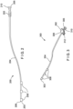
Fig. 2 shows a pressure sensor device configured for compatibility with the endoscopic device ofFig. 1A . -
Fig. 3 shows a flow sensor device configured for compatibility with the endoscopic device ofFig. 1A . -
Fig. 4A shows a transparent side view of a first embodiment of a motorized deployment device. -
Fig. 4B shows a transparent perspective view of the motorized deployment device ofFig. 4A . -
Fig. 5A shows a transparent side view of a second embodiment of a motorized deployment device. -
Fig. 5B shows a transparent perspective view of the motorized deployment device ofFig. 5A . -
Fig. 6 shows an exemplary Segura™ handle compatible with the motorized deployment devices ofFigs. 4A-5B and an elongated end effector device. -
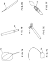
Figs. 7A-7F show exemplary elongated end effector devices compatible with a Segura™/Dakota™ handle. -
Fig. 8 shows a stepper motor control board. -
Fig. 9 shows a handle of an endoscopic device with a motor for controlling the deflection of a distal tip. -
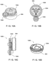
Figs. 10A-C show a gear train for driving a pull wire wheel of the device ofFig. 9 . -
Fig. 10D shows the pull wire wheel of the device ofFig. 9 fashioned with a gear. -
Fig. 11 shows the gear train ofFigs. 10A-C with a pulley. -
Fig. 12 shows an ergonomic button pad for controlling a scope tip and an elongated end effector device. - The present disclosure may be further understood with reference to the following description and the appended drawings, wherein like elements are referred to with the same reference numerals. The exemplary embodiments describe an endoscope having a scope handle with one or more external communication interfaces (e.g., USB ports) and accessory devices compatible with the endoscope and pluggable thereinto. For example, the accessory devices may include a pressure sensor, a temperature sensor, a flow sensor, an additional camera, an additional light, an optical sensor, a catheter, a laser time-of-flight distance sensor, a deployment device, other sensors or combinations thereof.
- In another embodiment, an accessory device is described that is a motorized deployment device for controlling an elongated end effector device to capture e.g. kidney stones or the like. The motorized deployment device is compatible with the endoscope or may be integrated with the endoscope in a monolithic handle. The elongated end effector device refers to any one of a number of devices compatible with and actuated by the motorized deployment device. For example, the elongated end effector device may be the retrieval device for capturing kidney stones, a laser fiber device, a therapy needle, snares, forceps, band ligation devices, etc. Any of the elongated end effector devices may be fitted with, for example, a Segura™ or Dakota™ handle sized and shaped to be used with the motorized deployment device. Thus, any elongated end effector device compatible with and fitted with a Segura™/Dakota™ handle (or a similar device) may also be used with the motorized deployment device.
- In still another embodiment, the endoscope handle has an motor for controlling the articulation of the distal tip of the endoscopic shaft. The motor may be, e.g., a stepper motor allowing for precise positioning and holding of the shaft tip and/or precise control of the end effector feature of the elongated device. The motor may be internal to the handle or may be externally coupled to the handle, e.g., connected to a pull wire wheel by a flexible drive shaft extension or the like.
- In each of the embodiments, the communication interfaces between the scope handle and the accessory device(s), whether internal or via external communication interfaces, are arranged so that an operating physician may operate the articulation of the distal shaft tip and control the accessory device in an ergonomic manner. For example, in one embodiment, where the motorized deployment device is connected to the scope handle via an external communication interface, the deflection knob for the distal shaft tip and the button control for the motorized deployment device are arranged so that both may be operated simultaneously or independently without overstressing the physician's hand.
- In another embodiment, where the motorized deployment device is monolithic with or otherwise compatible with the scope handle, a button pad may be used to operate both the shaft tip and the elongated device. The button pad may include, for example, four momentary buttons located on the bottom side of the scope handle and may be operated by the physician's grip hand thumb. Depressing a button causes a movement to occur to the scope shaft or the end effector, and releasing the button causes the stepper motor to stop and hold the current position. In another embodiment, a non-momentary button may be used such as a typical on/off switch. In still another embodiment, control is fully implemented remotely from the devices via, e.g., a console.
- The present embodiments have a data bus in the scope handle where data may be received via the various accessory devices and control for the devices may be implemented. The handle may be coupled to an endoscopic console or the like via a cable, with data from the devices being sent thereto or control of the devices being implemented therefrom. In some embodiments, data from one of the accessory devices and/or the endoscope may be used to control the operation of another one of the accessory devices and/or the endoscope. For example, a reading from a pressure sensor may trigger an operation of an irrigation mechanism. In another example the output from a laser-distance sensor may adjust/optimize the distance from a laser fiber tip to a ureteral stone via the stepper motor to maximize laser efficiency during stone fragmentation. In another embodiment the data from an accessory device is displayed on e.g. a monitor screen for the physician to evaluate and react accordingly.
-
Figs. 1A-1B show a front view and a rear view of anendoscopic device 100 compatible with powered and data accessories according to various exemplary embodiments of the present disclosure. Theendoscopic device 100 may be specific to a particular endoscopic procedure, such as, e.g., ureteroscopy, or may be a general-purpose device suitable for a wide variety of procedures. Thedevice 100 includes ahandle 102 connected to anendoscopic shaft 104 with a deflectingdistal tip 106 at adistal end 103. Thedistal tip 106 has a camera and may, for example, have full 270° deflection capabilities in more than one direction for viewing patient anatomy as would be understood by those skilled in the art. - The
handle 102 of theendoscopic device 100 has a plurality of elements configured to facilitate the endoscopic procedure. Acable 108 extends from thehandle 102 and is configured for attachment to an electronic device (not pictured) such as e.g. a computer system, a console, a microcontroller, etc. for providing power, analyzing endoscopic data, controlling the endoscopic intervention, or performing other functions. The electronic device to which thecable 108 is connected may have functionality for recognizing and exchanging data with other endoscopic accessories, to be described in detail below. Thehandle 102 has agrip area 118 for the operating physician to grasp while performing the endoscopic procedure. Adeflection knob 116 at aproximal end 105 of the device may be actuated to control the deflection of thedistal tip 106 as would be understood by those skilled in the art. Even when an endoscope has a motorized deflection means, to be described in detail below, a short handle version of thedeflection knob 116 is present, in this embodiment, for manually straightening thedistal tip 106 and removing theshaft 104 from the patient anatomy in case of e.g. power failure. - The
handle 102 further has at least one communication interface for attaching accessory devices. In the present embodiment, thehandle 102 has afirst communication interface 112 andsecond communication interface 114 that are, in this embodiment, Universal Serial Bus type-C (USB-C) ports. However, more or less communication interface of various types, including, for example, custom interfaces, may be used. In other embodiments, thehandle 102 has only one communication interface but may receive e.g. a USB hub with multiple ports for connecting multiple accessories. The communication interfaces 112, 114 may provide power to the accessory devices in addition to exchanging data therewith. Thus, the accessory devices need not have separate cables running to the console or a battery that adds additional weigh to thehandle 102. The accessory device may be uniquely associated with thedevice 100 and recognized by the console through "plug and play" functionality without any user setup required. - A T-
connector 110 extends from a distal portion of thehandle 102 and provides twoports endoscopic shaft 104. In this embodiment, the first andsecond ports first port 124 facing distally and thesecond port 126 facing proximally. An accessory device or an elongated end effector device may be passed through either one of the first andsecond ports second port 126 may be preferred when the device is proximal to the T-connector 110. In another embodiment, a Y-connector is used with first and second ports both facing proximally, such that two devices may be passed into the working channel of theendoscopic shaft 104 from a position proximal to the Y-connector. - Various accessory devices may be mated with either of the two
communication interfaces interfaces first communication interface 112 is located distally on thehandle 102. Certain of the accessory devices have corresponding communication interfaces, e.g., male USB-C ports, extending from the devices that lend themselves to spatial compatibility with thefirst communication interface 112. - For example,
Fig. 2 shows apressure sensor device 200 configured for compatibility with theendoscopic device 100, particularly with thefirst communication interface 112 of theendoscopic device 100. Thepressure sensor device 200 has acommunication interface 202 that may be mated with, e.g., inserted into, thefirst communication interface 112 of theendoscopic device 100. Thepressure sensor device 200 has ashaft 204 extending from aproximal end 205 of thedevice 200 to adistal end 203 of thedevice 200. Theshaft 204 has a through-lumen, i.e., channel, extending through its length. The proximal end of theshaft 204 has afemale Luer hub 210 extending therefrom and thecommunication interface 202 adjacent thereto. Thecommunication interface 112 of theendoscopic device 100 is angled so that when thepressure sensor device 200 is attached to theendoscopic device 100, theLuer hub 210 is oriented in a manner similar to thesecond port 126 of the T-connector 110. Thus, thepressure sensor device 200 is more easily coupled with a male Luer port for e.g. fluid communication during use. - The
pressure sensor device 200 has apressure sensor 206 at a distal end of theshaft 204 and a plurality ofclips 208 adjacent thereto for securing theshaft 204 of thepressure sensor device 200 to theendoscopic shaft 104. Although the present embodiment uses theclips 208, theshaft 204 may be secured to theendoscopic shaft 104 by other means such as, e.g., holders or the like. - As noted above, the
pressure sensor device 200 may also be mated with thesecond communication interface 114 of theendoscopic device 100. However, in the presently described embodiment, mating with thefirst communication interface 112 is preferable in view of the ease with which theshaft 204 of thepressure sensor device 200 may be clipped to theshaft 104 of theendoscopic device 100 as well as the positioning of themedical luer hub 210. - In another example,
Fig. 3 shows aflow sensor device 300 configured for compatibility with theendoscopic device 100, particularly with thefirst communication interface 112 of the endoscopic device. Similar to thepressure sensor device 200, theflow sensor device 300 has acommunication interface 302 that may be mated with thefirst communication interface 112 of theendoscopic device 100. Theflow sensor device 300 has ashaft 304 extending from aproximal end 305 of thedevice 300 to adistal end 303 of thedevice 300. Theshaft 304 has a through-lumen extending through its length. The proximal end of theshaft 304 has afemale Luer hub 310 extending therefrom, thecommunication interface 302 adjacent thereto and ahandle 312. Similar to thepressure sensor device 200, theflow sensor device 300 is easily coupled with a male Luer port for fluid communication or any other reason. - The
flow sensor device 300 has aflow sensor 306 adjacent to thehandle 312 and a plurality ofclips 308 adjacent to a distal end of theshaft 304 for securing theshaft 304 of theflow sensor device 300 to theendoscopic shaft 104. Similar to thepressure sensor device 200, theflow sensor device 300 may use attachment means other than theclips 308 such as, e.g. holders or the like. Thepressure sensor device 200 may also be mated with thesecond communication interface 114 of theendoscopic device 100, however, mating with thefirst communication interface 112 is preferable in view of the spatial benefits discussed above. - The
second communication interface 114 is positioned proximally on thehandle 102 and is compatible with accessory devices configured for insertion through a working channel of theendoscopic shaft 104 via, for example, thesecond port 126. For example, an accessory device such as an additional camera, an additional light, an optical sensor, or other device may be mated with thesecond communication interface 114 and inserted into the working channel. In this way, the cables/shafts of the devices are out of the way of the operating physician and can be used without significant bending of the accessory. - However, these devices may also have a flexible cable that is inserted into the
first communication interface 112 and flexed into the working channel without damaging the cable. Because thesecond communication interface 114 is proximal to the T-connector 110, with thesecond port 126 of the T-connector 110 directed proximally, there may be instances where a fluid being used during a ureteroscopic procedure leaks and/or splashes proximally. Thus, the proximalsecond communication interface 114 may have a fluid seal such as a Tuohy borst adapter, a UroLok™ or a Gateway™. Theconsole cable 108 of theendoscopic device 100 may be associated with one of the communication interfaces 112, 114 such that an interface on thehandle 102 is not necessary. For example, thecable 108 may be bifurcated and have an interface, e.g., USB port, extending from the bifurcated part of thecable 108. - The
handle 102 of theendoscopic device 100 in the present embodiment has twomount holes motorized deployment device 400 compatible with an elongated end effector device. The elongated end effector device may be any one of a number of devices having a variety of purposes such as, e.g., capturing and removing objects such as kidney stones, to be explained in further detail below. -
Fig. 4A shows a transparent side view andFig. 4B shows a transparent perspective view of themotorized deployment device 400. Themotorized deployment device 400 may be coupled to theendoscopic device 100 at the mount holes 120, 122 with corresponding mount pins 402, 404. Thedeployment device 400 has acommunication interface 406 that may be mated with, e.g., inserted into, thesecond communication interface 114 of theendoscopic device 100. Thecommunication interface 406 may be, e.g., a male USB-C port. Thecommunication interface 406 is connected via aflexible cable 408 to acontrol board 410 for amotor 412. Thecontrol board 410 includes an electrical port, in this case for connecting a USB, driver circuitry and motor terminals for connecting themotor 412. Themotor 412 may be, e.g., a stepper motor. - The
motor 412 may be actuated by a signal provided by e.g. thebutton pad 1200 shown inFig. 12 . In another embodiment, the signal is generated in response to an endoscopic sensor reading. If theflexible cable 408 is sufficiently long thecommunication interface 406 may be mated with thefirst communication interface 112 of theendoscopic device 100, however, in the presently described embodiment, themotorized deployment device 400 is particularly suited for connection via thesecond communication interface 114. The connection to thedeployment device 400 via one of the communication interfaces 112, 114 allows for actuation of thedeployment device 400 via controls on thehandle 102. - The
motorized deployment device 400 has ahandle coupler 414 extending from adistal end 403 of thedevice 400 to aproximal end 405 of thedevice 400. Thehandle coupler 414 is configured to receive a handle of the elongated end effector device, to be described below with respect toFigs. 6-7 . The elongated end effector device comprises a pull wire and an outer sheath to be fed through the working channel of theshaft 104 via the T-connector 110 of theendoscopic device 100 or other embodiments of the endoscopic device. The elongated end effector device includes a handle at the proximal end and an end effector at the distal end of the pull wire, the end effector being actuatable by a slide on the handle between an extended open and a retracted closed state for, for example, grasping objects or extending/retracting a laser fiber or a therapy needle during the endoscopic procedure. - In an alternate embodiment, the elongated end effector device and the
motorized deployment device 400 are fashioned in a single monolithic unit. The end effector is actuatable via linear motion of acarrier 416 coupled to the slide of the elongated end effector device handle, to be described in detail below. For example, when the elongated device handle is inserted into thehandle coupler 414, distal movement of thecarrier 416 may cause the slide of the elongated end effector device to close the end effector, while proximal movement of thecarrier 416 may cause the end effector to open. The motion of thecarrier 416 is implemented via themotor 412 via an actuation linkage internal to thedeployment device 400, to be described below. - The
carrier 416 of thedeployment device 400 is configured to slide within achannel 424 of thedevice 400. Thechannel 424 prevents any movement other than the proximal/distal sliding. Thecarrier 416 has aslot 422 where apin 420 is configured to slide, thepin 420 being connected to themotor 412 via anarm 418. When themotor 412 is actuated thearm 418 is caused to rotate about apredefined arc 426. The linkage of thepin 420 with theslot 422 translates the angular motion of thearm 418 into linear motion of thecarrier 416. Theslot 422 allows thepin 420 to translate slightly in a direction orthogonal to the proximal/distal direction while driving thecarrier 416 in the proximal/distal direction. When thecarrier 416 is brought to its most distal position the end effector is fully closed, and when thecarrier 416 is brought to its most proximal position the end effector is fully open, with varying degrees of openness/closedness between its most distal and most proximal positions. - In an alternate embodiment, as shown in
Figs. 5A-5B , adeployment device 500 extends from adistal end 503 to aproximal end 505 and may drive acarrier 516 using a lead screw in lieu of the linkage described with respect to thedeployment device 500. Similar to thefirst deployment device 400, thesecond deployment device 500 has mount pins 502, 504 for attaching thesecond deployment device 500 to theendoscopic device 100. Additionally, acommunication interface 506, aflexible cable 508, a driver andcontrol board 510, ahandle coupler 514, thecarrier 516 and achannel 528 are substantially similar to those described with respect to thedeployment device 400. However, thedeployment device 500 has two location options for a motor, both of which are coupled to lead screws, i.e. screws used as a linkage to translate rotational motion into linear motion. - In a first embodiment, a
motor 512 is disposed at a location adjacent to and oriented parallel to thechannel 528 housing thecarrier 516. When themotor 512 is actuated, alead screw 518 extending from the motor is rotated. Thelead screw 518 is coupled to a threaded through-hole 520 extending through a portion of thecarrier 516. Thus, as thelead screw 518 is rotated, thecarrier 516 is driven in a proximal/distal direction. In a second embodiment, amotor 522 is disposed at a location proximal to thechannel 528 housing thecarrier 516. Alead screw 524 extends from themotor 522 and is coupled to a threaded through-hole 526 extending through a proximal portion of thecarrier 516. Thesecond motor 522 drives thecarrier 516 in a substantially similar manner as thefirst motor 512. - In an alternate embodiment, the
devices carrier -
Fig. 6 shows an exemplary Segura™ handle 600 that may be fitted to any of the aforementioned elongated end effector devices. In another embodiment, a Dakota™ handle may be used, which is similar to the Segura™ handle but is modified to have a sure open trigger. Thus, thehandle 600 may be either of a Segura™ or a Dakota™ handle, depending on the elongated end effector device to which it is fitted, or may be a similar device for actuating an end effector device. - The Segura™ handle 600 has a
body 602 over which aslide 604 may slide. Amale luer 610 is attached to a distal end of theslide 604, while a shaft, i.e. pull wire of the elongated end effector device is held by ajaw vise 606 at a proximal end 605 of thebody 602. Acap 608 forces thejaws 606 closed around the shaft of the end effector device as thecap 608 is screwed onto thebody 602. Thebody 602 has a through-lumen (not pictured) for the shaft of the elongated end effector device. Thus, it may be seen that theslide 604 may move relative to thebody 602 and the shaft of the elongated end effector device. - An outer sheath of the end effector device is connected vis a female luer to the
male luer 610 and extends to cover the end effector at the distal end of the end effector device. When theslide 604 is moved distally it in turn moves the outer sheath distally over the end effector to close the end effector, and when theslide 604 is moved proximally it in turn moves the outer sheath proximally to uncover the distal end of the end effector, causing the self-opening, memory set end effector to open. A stroke-limiter in the Segura™ handle 600 governs the travel of theslide 604 relative to the end effector size, where T is the travel length of theslide 604. - As discussed previously, the
carriers deployment devices slide 604 of the Segura™/Dakota™ handle 600. Thus, when thedeployment device 400 is actuated to move thecarrier 416 in a proximal or distal direction, theslide 604 is correspondingly moved with respect to thebody 602 and the end effector of the end effector device is moved towards open or moved towards closed. -
Fig. 7 shows examples of elongated end effector devices compatible with the Segura™/Dakota™ handle 600, including a stone/particle retrieval basket.Figs. 7A-7F show a Zero Tip™ retrieval basket 702, alaser fiber device 704, atherapy needle 706, asnare 708,forceps 710 and aband ligator 712, respectively. Each of the elongated end effector devices may be fitted with a Segura™/Dakota™ handle and may be operated by thedeployment device - The motors described with respect to
deployment devices - The position of motor shaft is controlled by controlling the number of pulses. This feature makes the stepper motor to be well suited for an open-loop control system wherein the precise position of the shaft is maintained with an exact number of pulses without using a feedback sensor. If the step angle is smaller, the greater will be the number of steps per revolution and the higher will be the accuracy of the position obtained. The step angles can be as large as 90 degrees and as small as 0.72 degrees, however, the commonly used step angles are 1.8 degrees, 2.5 degrees, 7.5 degrees and 15 degrees.
- The direction of the shaft rotation depends on the sequence of pulses applied to the stator. The speed of the shaft or the average motor speed is directly proportional to the frequency (the rate of input pulses) of input pulses being applied at excitation windings. Therefore, if the frequency is low, the stepper motor rotates in steps and for high frequency, it continuously rotates like a DC motor due to inertia. Stepper motors continue to generate holding torque even at standstill. This means that the motor can be held at a stopped position without using a mechanical brake. The built-in pulse generation function (controller) allows the stepper motor to be driven via a directly connected personal computer, programmable controller or console. The stepper motor may achieve precise positioning via digital control, such control to be explained in further detail below.
-
Fig. 8 shows a steppermotor control board 800. Thecontrol board 800 comprises aUSB port 804 for connecting a USB cable andmotor terminals 802 for connecting a stepper motor. The steppermotor control board 800 may be used in either of thedeployment devices control boards motors motor 412 is a Servo motor, thecontrol board 412 is a Servo motor control board. The motor control board may be custom built. The motor may be powered via theUSB port 804, however, in another embodiment, the motor may be powered by batteries. - The
deployment device 400 hasbuttons 430 for controlling the carrier movement via thecontrol board 410 andmotor 412. Thedeployment device 400 preferably has at least twobuttons 430. For example, a first button may be depressed to advance the carrier in the distal direction and stop when the button is released. A second button may be depressed to advance the carrier in the proximal direction and stop when the button is released. A double tap of either button may bring the carrier to its most distal or most proximal position. Other button depression configurations may, for example, increase or decrease a speed of the carrier motion. - In the embodiment shown in
Fig. 12 , the mostproximal button 1202 is for scope shaft up direction (US) and the mostdistal button 1201 is for scope shaft down direction (US). In other countries the proximal button is for down and the distal button is for up. The twoside buttons - The placement of the
buttons 430 adjacent to thegrip area 118 anddeflection knob 116 of the endoscopic device 100 (when theendoscopic device 100 and thedeployment device 400 are attached) provides ergonomic benefits to the user of the devices. For example, a typical user may have difficulty operating a deployment device and scope deflection simultaneously, especially when the thumb is extended on thedeflection knob 116 at full deflection, and especially if the user has a small hand. The spatial configuration of thedevices buttons 430 anddeflection knob 116. Theretrieval device 500 similarly hasbuttons 530 for controlling the carrier movement in a similar manner as that described above. - In an alternate embodiment, voice commands may be implemented for controlling the end effector, such as, but not limited to, "open," "close," "stop," "faster," "slower," "load," etc.
- Different elongated end effector devices may be implemented in the
deployment device 400, each one having a distinct data set for controlling the end effector. For example, each end effector device may have different stop limits or stroke lengths for the carrier. However, through the "plug-and-play" functionality of theendoscopic device 100, the data sets may be automatically loaded to the controller. - Alternately, a type of elongated end effector device may be selected through a drop-down menu on the console. To assemble the Segura™ handle to the
deployment device 400 the carrier is moved to the most proximal position, e.g. by depressing thebutton 1203 ofFig. 12 , and the slide of the Segura™ handle is also moved to the most proximal position. This would match the contours of the slide and carrier such that the Segura™ handle is aligned and can be snapped into the deployment device.Button 1204, for example, is depressed to close or retract the end effector before the end effector is inserted into the working channel of the scope. To remove the elongated end effector device the end effector is closed by depressinge.g. button 1204. The shaft of the end effector is withdrawn and the Segura™ handle can be unclipped from the deployment device and put aside for later use. Another elongated device can be quickly exchanged for the previous elongated device to perform its function
In an alternate embodiment, theendoscopic device 100 anddeployment devices - In still another embodiment, the deflection of the
distal tip 106 of theendoscopic device 100 may be motorized/wired using the same control board, such as thecontrol board 800, as thedeployment device 400. In such an embodiment, a second driver and a second motor would be implemented in thehandle 102 for controlling thedistal tip 106. -
Fig. 9 shows ahandle 900 of an endoscopic device with amotor 902 for controlling the deflection of a distal tip. The endoscopic device in this embodiment has two pull wires (not shown) for deflecting the distal tip in either of two directions. Apull wire wheel 904 has a firstpull wire attachment 906 and a secondpull wire attachment 908. Themotor 902 is mounted in thehandle 900 with its drive shaft mounted in the center of thepull wire wheel 904. Adeflection knob 910 may be keyed to the rotation of thepull wire wheel 904 via a controller/driver and wiring (not shown). Thus, thedeflection knob 910 may operate as a switch and rotate independently from thepull wire wheel 904. - When pressure is applied on the
deflection knob 910 in a first direction themotor 902 will rotate thepull wire wheel 904 such that one of the two pull wires, e.g. the pull wire attached to the firstpull wire attachment 906, pulls the distal tip of the endoscopic device in one of the two directions. Similarly, when pressure is applied on thedeflection knob 910 in the second direction themotor 902 will rotate thepull wire wheel 904 such that the second of the two pull wires, e.g., the pull wire attached to the secondpull wire attachment 908, pulls the distal tip of the endoscopic device in the second of the two directions. Release of thedeflection knob 910 may stop themotor 902, allowing the position of the deflected distal tip to be maintained. The maximum angular travel of themotor 902 will be set to the limitations of the distal tip deflection. - A gear train may be used in the
handle 900 in lieu of themotor 902 driving thepull wire wheel 904 directly.Figs. 10A-C show a simple twogear train 1000 where asmaller gear 1002 drives alarger gear 1004 that rotates thepull wire wheel 904. Thelarger gear 1004 and thepull wire wheel 904 may be fashioned as a single part where the gear teeth extend from the circumference/perimeter of thepull wire wheel 904, as shown inFig. 10D .Fig. 11 shows a two-gear train 1100 with asmaller gear 1102 and alarger gear 1104 comprising apulley belt 1106. The mechanical advantage of the aforementioned embodiments is to use a less powerful/expensive motor. In thedevice 900, driving thepull wire wheel 904 directly will require a higher torque specification for the motor than would be needed using the gear train systems shown inFigs. 10-11 . - The aforementioned aspects of the present disclosure may be combined in various ways. In a first example, both the scope tip and the deployment device are motorized.
Fig. 12 shows anergonomic button pad 1200 for controlling the scope tip and the deployment device. Thebutton pad 1200 has afirst button 1201, asecond button 1202, athird button 1203 and afourth button 1204. Thebutton pad 1200 is also adjacent to a shorteneddeflection knob 1205. Thedeflection knob 1205 is shortened to allow the placement of thebutton pad 1200 adjacent to thedeflection knob 1205. In other embodiments, thedeflection knob 1205 may be eliminated completely, with the deflection of the scope tip being controlled by thebutton pad 1200. In another embodiment, the shortened deflection knob may be used as a safety/bailout feature in case of e.g. power failure, considering the deflected scope shaft has to be straightened before it can be removed from the body without injuries. - The
button pad 1200 is connected to a controller programmed for all aspects of the intervention. Thebutton pad 1200 is located on the bottom side of the scope handle and may be operated, for example, by the thumb of the scope handle grip hand. For example, the first andsecond buttons 1201, 1202 (opposite one another) may be used to deflect the scope tip in either of the two directions. The third andfourth buttons 1203, 1204 (opposite one another) may be used to control the opening/closing of the elongated end effector device. A fifth button may be implemented, such that when the fifth button is "on," the third andfourth buttons - In another embodiment, the buttons are implemented on a console, tablet (e.g., iPad) or the like and controlled remotely. Thus, the endoscopic device may be fashioned without control features implemented directly thereon, and may instead be controlled via Bluetooth, infrared remote, etc.
- It will be appreciated by those skilled in the art that changes may be made to the embodiments described above without departing from the scope of the invention as defined by the appended claims.
Claims (12)
- An endoscopic deployment device (400; 500), comprising:a body mountable on an endoscopic device (100), the body having a movable carrier (416; 516) couplable to an elongated end effector device, the elongated end effector device having an end effector shaft covered by an outer sheath and an end effector extending from a distal end of the end effector shaft, the outer sheath being sized and shaped for insertion through a working channel of an endoscopic shaft (104) of the endoscopic device (100), the body having a carrier channel (424; 528) sized for the movable carrier (416; 516) to slide therein, wherein the end effector is actuatable between an extended open position and a retracted closed position by sliding the movable carrier (416; 516) in the carrier channel (424; 528) which in turn slides the outer sheath over the end effector shaft to uncover or cover the end effector;a communication interface (406; 506) extending from the body and configured to be mated with a corresponding communication interface (112, 114) on the endoscopic device (100) on which the body is mounted to receive power therefrom and exchange data therewith; anda motor (412; 512) having a drive shaft coupled to the movable carrier (416; 516), the motor (412; 512) is configured to actuate in response to a signal, the actuation of the motor rotates the drive shaft and slides the movable carrier (416; 516) in the carrier channel (424; 528) to actuate the end effector.
- The endoscopic deployment device (400; 500) of claim 1, wherein an actuator on the endoscopic device (100) is configured to generate the signal.
- The endoscopic deployment device (400; 500) of claim 2, wherein the actuator is a button pad (1200) configured to control the motor (412; 512) via the mated communication interfaces of the endoscopic deployment device (400; 500) and the endoscopic device (100).
- The endoscopic deployment device (400; 500) of any one of claims 1-3, wherein the signal is generated in response to an endoscopic sensor reading.
- The endoscopic deployment device (400; 500) of any one of claims 1-4, wherein the motor (412; 512) is a stepper motor.
- The endoscopic deployment device (400) of claim 5, wherein the drive shaft has an arm (418) extending orthogonally therefrom coupled to a slot (422) in the movable carrier (416; 516) and the arm (418) has a pin (420) at an end of the arm (418) opposite the drive shaft, the pin (420) being coupled to the slot (422) so that, when the drive shaft rotates, the pin (420) slides in the slot (422) in a direction orthogonal to the carrier channel (424; 528) and the movable carrier (416; 516) slides in the carrier channel (424; 528).
- The endoscopic deployment device (500) of claim 5, wherein the drive shaft is a lead screw (518) coupled to a threaded through-hole (520) extending through a portion of the movable carrier (516) parallel to the carrier channel (528) so that, when the drive shaft rotates, the movable carrier (516) slides in the carrier channel (528).
- The endoscopic deployment device (400; 500) of claim 5, wherein a pinion gear is coupled to the drive shaft and to a rack that is an integral portion of the movable carrier (416; 516) so that, when the drive shaft rotates, the pinion gear drive the rack and the movable carrier (416; 516) slides in the carrier channel (424; 528).
- An endoscopic system including the endoscopic deployment device (400; 500) of any one of claims 1-8, wherein the endoscopic system further includes the endoscopic device (100) and the elongated end effector device.
- The endoscopic system of claim 9, wherein the elongated end effector device is a retrieval device for capturing objects at a distal end of the endoscopic shaft (104).
- The endoscopic system of any one of claims 9 or 10, wherein the elongated end effector device is a laser fiber or energy fiber for fragmenting or cauterizing objects at a distal end of the endoscopic shaft (104).
- The endoscopic system of any one of claims 9-11, wherein the endoscopic device (100) has a proximal communication interface (114) and a distal communication interface (112) and the communication interface (406; 506) of the endoscopic deployment device (400; 500) is compatible with the proximal communication interface (114) of the endoscopic device (100).
Priority Applications (1)
| Application Number | Priority Date | Filing Date | Title |
|---|---|---|---|
| EP25161071.3A EP4541291A3 (en) | 2019-09-24 | 2020-08-27 | Endoscopic device with usb port and powered accessories |
Applications Claiming Priority (2)
| Application Number | Priority Date | Filing Date | Title |
|---|---|---|---|
| US201962904909P | 2019-09-24 | 2019-09-24 | |
| PCT/US2020/048250 WO2021061337A1 (en) | 2019-09-24 | 2020-08-27 | Endoscopic device with usb port and powered accessories |
Related Child Applications (2)
| Application Number | Title | Priority Date | Filing Date |
|---|---|---|---|
| EP25161071.3A Division-Into EP4541291A3 (en) | 2019-09-24 | 2020-08-27 | Endoscopic device with usb port and powered accessories |
| EP25161071.3A Division EP4541291A3 (en) | 2019-09-24 | 2020-08-27 | Endoscopic device with usb port and powered accessories |
Publications (2)
| Publication Number | Publication Date |
|---|---|
| EP4033954A1 EP4033954A1 (en) | 2022-08-03 |
| EP4033954B1 true EP4033954B1 (en) | 2025-04-09 |
Family
ID=72428377
Family Applications (2)
| Application Number | Title | Priority Date | Filing Date |
|---|---|---|---|
| EP25161071.3A Pending EP4541291A3 (en) | 2019-09-24 | 2020-08-27 | Endoscopic device with usb port and powered accessories |
| EP20768470.5A Active EP4033954B1 (en) | 2019-09-24 | 2020-08-27 | Endoscopic device with usb port and powered accessories |
Family Applications Before (1)
| Application Number | Title | Priority Date | Filing Date |
|---|---|---|---|
| EP25161071.3A Pending EP4541291A3 (en) | 2019-09-24 | 2020-08-27 | Endoscopic device with usb port and powered accessories |
Country Status (4)
| Country | Link |
|---|---|
| US (2) | US11918186B2 (en) |
| EP (2) | EP4541291A3 (en) |
| CN (2) | CN120323894A (en) |
| WO (1) | WO2021061337A1 (en) |
Families Citing this family (10)
| Publication number | Priority date | Publication date | Assignee | Title |
|---|---|---|---|---|
| DE102018208564A1 (en) | 2018-05-30 | 2019-12-05 | Kardion Gmbh | Controllable introducer sheath |
| DE102018208555A1 (en) | 2018-05-30 | 2019-12-05 | Kardion Gmbh | Apparatus for anchoring a cardiac assist system in a blood vessel, method of operation, and method of making a device and cardiac assist system |
| DE102018208537A1 (en) | 2018-05-30 | 2019-12-05 | Kardion Gmbh | Device for connecting a cardiac assist system to an insertion device and method for producing a device for connecting a cardiac assist system to an insertion device |
| DE102018211297A1 (en) | 2018-07-09 | 2020-01-09 | Kardion Gmbh | Cardiac support system and method for monitoring the integrity of a support structure of a cardiac support system |
| US11723516B2 (en) | 2019-12-12 | 2023-08-15 | Boston Scientific Scimed Inc. | Powered endoscopic device with haptic feedback |
| US11986199B2 (en) * | 2020-07-16 | 2024-05-21 | EndoGear, LLC | Grasping device for independent tissue manipulation during gastrointestinal endoscopic procedures and methods of use |
| US12589237B2 (en) | 2020-11-20 | 2026-03-31 | Kardion Gmbh | Mechanical circulatory support system with guidewire aid |
| CN119136719A (en) * | 2022-02-01 | 2024-12-13 | C·R·巴德股份有限公司 | Ureteroscopic device and system including catheter control system and related methods |
| US12588956B2 (en) | 2022-05-20 | 2026-03-31 | Boston Scientific Scimed, Inc. | Trajectory tracking for medical device |
| EP4461197A1 (en) * | 2023-05-11 | 2024-11-13 | Ambu A/S | Endoscope with an elevator element and control module for the endoscope |
Family Cites Families (13)
| Publication number | Priority date | Publication date | Assignee | Title |
|---|---|---|---|---|
| US4178920A (en) * | 1977-10-03 | 1979-12-18 | American Hospital Supply Corporation | Urological instrument with deflecting element |
| JPS57117824A (en) * | 1981-01-14 | 1982-07-22 | Olympus Optical Co | Treating tool inserting and pulling out apparatus of endoscope |
| US5159446A (en) * | 1991-06-21 | 1992-10-27 | Olympus Optical Co., Ltd. | Electronic endoscope system provided with a separate camera controlling unit and motor controlling unit |
| DK200001852A (en) * | 1999-12-14 | 2001-06-15 | Asahi Optical Co Ltd | Manipulation section for an endoscopic treatment instrument |
| JP4047563B2 (en) * | 2001-09-05 | 2008-02-13 | オリンパス株式会社 | Endoscope |
| US7846107B2 (en) * | 2005-05-13 | 2010-12-07 | Boston Scientific Scimed, Inc. | Endoscopic apparatus with integrated multiple biopsy device |
| US20070225562A1 (en) * | 2006-03-23 | 2007-09-27 | Ethicon Endo-Surgery, Inc. | Articulating endoscopic accessory channel |
| WO2009084345A1 (en) * | 2007-12-28 | 2009-07-09 | Olympus Medical Systems Corp. | Medical instrument system |
| JP5236035B2 (en) * | 2011-03-15 | 2013-07-17 | 富士フイルム株式会社 | Endoscope insertion aid |
| SG11201502034WA (en) * | 2012-09-19 | 2015-05-28 | Univ Nanyang Tech | Flexible master - slave robotic endoscopy system |
| US20140200402A1 (en) * | 2013-01-16 | 2014-07-17 | Phillip Jack Snoke | Medical Device Introduction Systems and Methods |
| US9351728B2 (en) * | 2013-06-28 | 2016-05-31 | Covidien Lp | Articulating apparatus for endoscopic procedures |
| JP2017213367A (en) | 2016-05-26 | 2017-12-07 | MakeWay合同会社 | Endoscope and treatment tool drive module |
-
2020
- 2020-08-27 CN CN202510483687.7A patent/CN120323894A/en active Pending
- 2020-08-27 US US16/948,027 patent/US11918186B2/en active Active
- 2020-08-27 WO PCT/US2020/048250 patent/WO2021061337A1/en not_active Ceased
- 2020-08-27 EP EP25161071.3A patent/EP4541291A3/en active Pending
- 2020-08-27 EP EP20768470.5A patent/EP4033954B1/en active Active
- 2020-08-27 CN CN202080067147.6A patent/CN114466614B/en active Active
-
2024
- 2024-02-01 US US18/429,724 patent/US12611090B2/en active Active
Also Published As
| Publication number | Publication date |
|---|---|
| US20240164625A1 (en) | 2024-05-23 |
| US12611090B2 (en) | 2026-04-28 |
| EP4541291A3 (en) | 2025-07-09 |
| US20210085153A1 (en) | 2021-03-25 |
| EP4033954A1 (en) | 2022-08-03 |
| WO2021061337A1 (en) | 2021-04-01 |
| CN114466614A (en) | 2022-05-10 |
| CN114466614B (en) | 2025-04-29 |
| CN120323894A (en) | 2025-07-18 |
| EP4541291A2 (en) | 2025-04-23 |
| US11918186B2 (en) | 2024-03-05 |
Similar Documents
| Publication | Publication Date | Title |
|---|---|---|
| US12611090B2 (en) | Endoscopic device with USB port and powered accessories | |
| US10285676B2 (en) | Endoscopic surgical instrument | |
| US20110021871A1 (en) | Laparoscopic surgical instrument | |
| CN102469995B (en) | Handle piece for hybrid surgical robot system | |
| TWI795414B (en) | Surgical apparatus and surgical instrument thereof | |
| EP1568305B1 (en) | Endoscope treatment system | |
| US10085806B2 (en) | Minimally invasive instrument for robotic surgery | |
| US8282543B2 (en) | Surgical instrument and endoscope surgical system having surgical instrument | |
| JP2023098958A (en) | ROBOTIC SURGICAL DEVICES, SYSTEMS AND RELATED METHODS | |
| JP5322714B2 (en) | Electric bending operation device | |
| CN101610710B (en) | Articulated bending mechanism and articulated medical device with articulated bending mechanism | |
| CN101272740B (en) | surgical device | |
| JP2002224016A (en) | Endoscope | |
| US12383117B2 (en) | Powered endoscopic device with haptic feedback | |
| KR20150084837A (en) | Systems and methods for a dual-control surgical instrument | |
| EP3515324B1 (en) | Robotic surgical system | |
| KR20170125174A (en) | Robot apparatus for minimally invasive surgery | |
| CN211381751U (en) | Rotation mechanism and surgical robot | |
| WO2023093841A1 (en) | Surgical instrument protection apparatus, surgical instrument, mounting portion, and surgical instrument assembly | |
| KR20200030209A (en) | Multi degree-of-freedom laparoscopic apparatus using disposable surgical robot tool | |
| CN110840563A (en) | An opening and closing mechanism and surgical robot | |
| JP3980926B2 (en) | Surgical tools | |
| KR20200047137A (en) | wearable surgical robot arm | |
| CN113951948B (en) | Surgical instrument control unit | |
| US20250387118A1 (en) | Surgical instrument |
Legal Events
| Date | Code | Title | Description |
|---|---|---|---|
| STAA | Information on the status of an ep patent application or granted ep patent |
Free format text: STATUS: UNKNOWN |
|
| STAA | Information on the status of an ep patent application or granted ep patent |
Free format text: STATUS: THE INTERNATIONAL PUBLICATION HAS BEEN MADE |
|
| PUAI | Public reference made under article 153(3) epc to a published international application that has entered the european phase |
Free format text: ORIGINAL CODE: 0009012 |
|
| STAA | Information on the status of an ep patent application or granted ep patent |
Free format text: STATUS: REQUEST FOR EXAMINATION WAS MADE |
|
| 17P | Request for examination filed |
Effective date: 20220106 |
|
| AK | Designated contracting states |
Kind code of ref document: A1 Designated state(s): AL AT BE BG CH CY CZ DE DK EE ES FI FR GB GR HR HU IE IS IT LI LT LU LV MC MK MT NL NO PL PT RO RS SE SI SK SM TR |
|
| DAV | Request for validation of the european patent (deleted) | ||
| DAX | Request for extension of the european patent (deleted) | ||
| GRAP | Despatch of communication of intention to grant a patent |
Free format text: ORIGINAL CODE: EPIDOSNIGR1 |
|
| STAA | Information on the status of an ep patent application or granted ep patent |
Free format text: STATUS: GRANT OF PATENT IS INTENDED |
|
| INTG | Intention to grant announced |
Effective date: 20240624 |
|
| RAP3 | Party data changed (applicant data changed or rights of an application transferred) |
Owner name: BOSTON SCIENTIFIC SCIMED, INC. |
|
| GRAJ | Information related to disapproval of communication of intention to grant by the applicant or resumption of examination proceedings by the epo deleted |
Free format text: ORIGINAL CODE: EPIDOSDIGR1 |
|
| STAA | Information on the status of an ep patent application or granted ep patent |
Free format text: STATUS: REQUEST FOR EXAMINATION WAS MADE |
|
| GRAP | Despatch of communication of intention to grant a patent |
Free format text: ORIGINAL CODE: EPIDOSNIGR1 |
|
| STAA | Information on the status of an ep patent application or granted ep patent |
Free format text: STATUS: GRANT OF PATENT IS INTENDED |
|
| INTC | Intention to grant announced (deleted) | ||
| INTG | Intention to grant announced |
Effective date: 20241104 |
|
| GRAS | Grant fee paid |
Free format text: ORIGINAL CODE: EPIDOSNIGR3 |
|
| GRAA | (expected) grant |
Free format text: ORIGINAL CODE: 0009210 |
|
| STAA | Information on the status of an ep patent application or granted ep patent |
Free format text: STATUS: THE PATENT HAS BEEN GRANTED |
|
| AK | Designated contracting states |
Kind code of ref document: B1 Designated state(s): AL AT BE BG CH CY CZ DE DK EE ES FI FR GB GR HR HU IE IS IT LI LT LU LV MC MK MT NL NO PL PT RO RS SE SI SK SM TR |
|
| REG | Reference to a national code |
Ref country code: GB Ref legal event code: FG4D |
|
| REG | Reference to a national code |
Ref country code: CH Ref legal event code: EP |
|
| REG | Reference to a national code |
Ref country code: DE Ref legal event code: R096 Ref document number: 602020049156 Country of ref document: DE |
|
| REG | Reference to a national code |
Ref country code: IE Ref legal event code: FG4D |
|
| REG | Reference to a national code |
Ref country code: NL Ref legal event code: FP |
|
| PGFP | Annual fee paid to national office [announced via postgrant information from national office to epo] |
Ref country code: NL Payment date: 20250723 Year of fee payment: 6 |
|
| REG | Reference to a national code |
Ref country code: AT Ref legal event code: MK05 Ref document number: 1782739 Country of ref document: AT Kind code of ref document: T Effective date: 20250409 |
|
| PG25 | Lapsed in a contracting state [announced via postgrant information from national office to epo] |
Ref country code: PT Free format text: LAPSE BECAUSE OF FAILURE TO SUBMIT A TRANSLATION OF THE DESCRIPTION OR TO PAY THE FEE WITHIN THE PRESCRIBED TIME-LIMIT Effective date: 20250811 Ref country code: ES Free format text: LAPSE BECAUSE OF FAILURE TO SUBMIT A TRANSLATION OF THE DESCRIPTION OR TO PAY THE FEE WITHIN THE PRESCRIBED TIME-LIMIT Effective date: 20250409 Ref country code: FI Free format text: LAPSE BECAUSE OF FAILURE TO SUBMIT A TRANSLATION OF THE DESCRIPTION OR TO PAY THE FEE WITHIN THE PRESCRIBED TIME-LIMIT Effective date: 20250409 |
|
| PGFP | Annual fee paid to national office [announced via postgrant information from national office to epo] |
Ref country code: DE Payment date: 20250724 Year of fee payment: 6 |
|
| REG | Reference to a national code |
Ref country code: LT Ref legal event code: MG9D |
|
| PG25 | Lapsed in a contracting state [announced via postgrant information from national office to epo] |
Ref country code: GR Free format text: LAPSE BECAUSE OF FAILURE TO SUBMIT A TRANSLATION OF THE DESCRIPTION OR TO PAY THE FEE WITHIN THE PRESCRIBED TIME-LIMIT Effective date: 20250710 Ref country code: NO Free format text: LAPSE BECAUSE OF FAILURE TO SUBMIT A TRANSLATION OF THE DESCRIPTION OR TO PAY THE FEE WITHIN THE PRESCRIBED TIME-LIMIT Effective date: 20250709 |
|
| PG25 | Lapsed in a contracting state [announced via postgrant information from national office to epo] |
Ref country code: PL Free format text: LAPSE BECAUSE OF FAILURE TO SUBMIT A TRANSLATION OF THE DESCRIPTION OR TO PAY THE FEE WITHIN THE PRESCRIBED TIME-LIMIT Effective date: 20250409 |
|
| PG25 | Lapsed in a contracting state [announced via postgrant information from national office to epo] |
Ref country code: BG Free format text: LAPSE BECAUSE OF FAILURE TO SUBMIT A TRANSLATION OF THE DESCRIPTION OR TO PAY THE FEE WITHIN THE PRESCRIBED TIME-LIMIT Effective date: 20250409 |
|
| PGFP | Annual fee paid to national office [announced via postgrant information from national office to epo] |
Ref country code: GB Payment date: 20250724 Year of fee payment: 6 |
|
| PG25 | Lapsed in a contracting state [announced via postgrant information from national office to epo] |
Ref country code: HR Free format text: LAPSE BECAUSE OF FAILURE TO SUBMIT A TRANSLATION OF THE DESCRIPTION OR TO PAY THE FEE WITHIN THE PRESCRIBED TIME-LIMIT Effective date: 20250409 |
|
| PG25 | Lapsed in a contracting state [announced via postgrant information from national office to epo] |
Ref country code: AT Free format text: LAPSE BECAUSE OF FAILURE TO SUBMIT A TRANSLATION OF THE DESCRIPTION OR TO PAY THE FEE WITHIN THE PRESCRIBED TIME-LIMIT Effective date: 20250409 |
|
| PG25 | Lapsed in a contracting state [announced via postgrant information from national office to epo] |
Ref country code: RS Free format text: LAPSE BECAUSE OF FAILURE TO SUBMIT A TRANSLATION OF THE DESCRIPTION OR TO PAY THE FEE WITHIN THE PRESCRIBED TIME-LIMIT Effective date: 20250709 |
|
| PGFP | Annual fee paid to national office [announced via postgrant information from national office to epo] |
Ref country code: IE Payment date: 20250725 Year of fee payment: 6 |
|
| PG25 | Lapsed in a contracting state [announced via postgrant information from national office to epo] |
Ref country code: IS Free format text: LAPSE BECAUSE OF FAILURE TO SUBMIT A TRANSLATION OF THE DESCRIPTION OR TO PAY THE FEE WITHIN THE PRESCRIBED TIME-LIMIT Effective date: 20250809 |
|
| PG25 | Lapsed in a contracting state [announced via postgrant information from national office to epo] |
Ref country code: LV Free format text: LAPSE BECAUSE OF FAILURE TO SUBMIT A TRANSLATION OF THE DESCRIPTION OR TO PAY THE FEE WITHIN THE PRESCRIBED TIME-LIMIT Effective date: 20250409 |
|
| REG | Reference to a national code |
Ref country code: DE Ref legal event code: R097 Ref document number: 602020049156 Country of ref document: DE |
|
| PG25 | Lapsed in a contracting state [announced via postgrant information from national office to epo] |
Ref country code: DK Free format text: LAPSE BECAUSE OF FAILURE TO SUBMIT A TRANSLATION OF THE DESCRIPTION OR TO PAY THE FEE WITHIN THE PRESCRIBED TIME-LIMIT Effective date: 20250409 Ref country code: SM Free format text: LAPSE BECAUSE OF FAILURE TO SUBMIT A TRANSLATION OF THE DESCRIPTION OR TO PAY THE FEE WITHIN THE PRESCRIBED TIME-LIMIT Effective date: 20250409 |
|
| PG25 | Lapsed in a contracting state [announced via postgrant information from national office to epo] |
Ref country code: CZ Free format text: LAPSE BECAUSE OF FAILURE TO SUBMIT A TRANSLATION OF THE DESCRIPTION OR TO PAY THE FEE WITHIN THE PRESCRIBED TIME-LIMIT Effective date: 20250409 |
|
| PG25 | Lapsed in a contracting state [announced via postgrant information from national office to epo] |
Ref country code: EE Free format text: LAPSE BECAUSE OF FAILURE TO SUBMIT A TRANSLATION OF THE DESCRIPTION OR TO PAY THE FEE WITHIN THE PRESCRIBED TIME-LIMIT Effective date: 20250409 |
|
| PG25 | Lapsed in a contracting state [announced via postgrant information from national office to epo] |
Ref country code: SK Free format text: LAPSE BECAUSE OF FAILURE TO SUBMIT A TRANSLATION OF THE DESCRIPTION OR TO PAY THE FEE WITHIN THE PRESCRIBED TIME-LIMIT Effective date: 20250409 |
|
| PG25 | Lapsed in a contracting state [announced via postgrant information from national office to epo] |
Ref country code: IT Free format text: LAPSE BECAUSE OF FAILURE TO SUBMIT A TRANSLATION OF THE DESCRIPTION OR TO PAY THE FEE WITHIN THE PRESCRIBED TIME-LIMIT Effective date: 20250409 |
|
| PG25 | Lapsed in a contracting state [announced via postgrant information from national office to epo] |
Ref country code: RO Free format text: LAPSE BECAUSE OF FAILURE TO SUBMIT A TRANSLATION OF THE DESCRIPTION OR TO PAY THE FEE WITHIN THE PRESCRIBED TIME-LIMIT Effective date: 20250409 |
|
| PLBE | No opposition filed within time limit |
Free format text: ORIGINAL CODE: 0009261 |
|
| STAA | Information on the status of an ep patent application or granted ep patent |
Free format text: STATUS: NO OPPOSITION FILED WITHIN TIME LIMIT |
|
| REG | Reference to a national code |
Ref country code: CH Ref legal event code: L10 Free format text: ST27 STATUS EVENT CODE: U-0-0-L10-L00 (AS PROVIDED BY THE NATIONAL OFFICE) Effective date: 20260218 |
|
| 26N | No opposition filed |
Effective date: 20260112 |
|
| REG | Reference to a national code |
Ref country code: CH Ref legal event code: H13 Free format text: ST27 STATUS EVENT CODE: U-0-0-H10-H13 (AS PROVIDED BY THE NATIONAL OFFICE) Effective date: 20260324 |
|
| PG25 | Lapsed in a contracting state [announced via postgrant information from national office to epo] |
Ref country code: MC Free format text: LAPSE BECAUSE OF FAILURE TO SUBMIT A TRANSLATION OF THE DESCRIPTION OR TO PAY THE FEE WITHIN THE PRESCRIBED TIME-LIMIT Effective date: 20250409 |
|
| PG25 | Lapsed in a contracting state [announced via postgrant information from national office to epo] |
Ref country code: LU Free format text: LAPSE BECAUSE OF NON-PAYMENT OF DUE FEES Effective date: 20250827 |
|
| PG25 | Lapsed in a contracting state [announced via postgrant information from national office to epo] |
Ref country code: CH Free format text: LAPSE BECAUSE OF NON-PAYMENT OF DUE FEES Effective date: 20250831 |