EP4033934B1 - Foot support components for articles of footwear - Google Patents
Foot support components for articles of footwear Download PDFInfo
- Publication number
- EP4033934B1 EP4033934B1 EP20789381.9A EP20789381A EP4033934B1 EP 4033934 B1 EP4033934 B1 EP 4033934B1 EP 20789381 A EP20789381 A EP 20789381A EP 4033934 B1 EP4033934 B1 EP 4033934B1
- Authority
- EP
- European Patent Office
- Prior art keywords
- foot support
- medial
- lateral
- edge
- component
- Prior art date
- Legal status (The legal status is an assumption and is not a legal conclusion. Google has not performed a legal analysis and makes no representation as to the accuracy of the status listed.)
- Active
Links
Images






Classifications
-
- A—HUMAN NECESSITIES
- A43—FOOTWEAR
- A43B—CHARACTERISTIC FEATURES OF FOOTWEAR; PARTS OF FOOTWEAR
- A43B7/00—Footwear with health or hygienic arrangements
- A43B7/14—Footwear with health or hygienic arrangements with foot-supporting parts
- A43B7/1405—Footwear with health or hygienic arrangements with foot-supporting parts with pads or holes on one or more locations, or having an anatomical or curved form
- A43B7/141—Footwear with health or hygienic arrangements with foot-supporting parts with pads or holes on one or more locations, or having an anatomical or curved form having an anatomical or curved form
-
- A—HUMAN NECESSITIES
- A43—FOOTWEAR
- A43B—CHARACTERISTIC FEATURES OF FOOTWEAR; PARTS OF FOOTWEAR
- A43B7/00—Footwear with health or hygienic arrangements
- A43B7/14—Footwear with health or hygienic arrangements with foot-supporting parts
-
- A—HUMAN NECESSITIES
- A43—FOOTWEAR
- A43B—CHARACTERISTIC FEATURES OF FOOTWEAR; PARTS OF FOOTWEAR
- A43B13/00—Soles; Sole-and-heel integral units
- A43B13/14—Soles; Sole-and-heel integral units characterised by the constructive form
- A43B13/18—Resilient soles
- A43B13/181—Resiliency achieved by the structure of the sole
-
- A—HUMAN NECESSITIES
- A43—FOOTWEAR
- A43B—CHARACTERISTIC FEATURES OF FOOTWEAR; PARTS OF FOOTWEAR
- A43B13/00—Soles; Sole-and-heel integral units
- A43B13/14—Soles; Sole-and-heel integral units characterised by the constructive form
- A43B13/18—Resilient soles
- A43B13/181—Resiliency achieved by the structure of the sole
- A43B13/183—Leaf springs
-
- A—HUMAN NECESSITIES
- A43—FOOTWEAR
- A43B—CHARACTERISTIC FEATURES OF FOOTWEAR; PARTS OF FOOTWEAR
- A43B21/00—Heels; Top-pieces or top-lifts
- A43B21/24—Heels; Top-pieces or top-lifts characterised by the constructive form
- A43B21/32—Resilient supports for the heel of the foot
-
- A—HUMAN NECESSITIES
- A43—FOOTWEAR
- A43B—CHARACTERISTIC FEATURES OF FOOTWEAR; PARTS OF FOOTWEAR
- A43B7/00—Footwear with health or hygienic arrangements
- A43B7/14—Footwear with health or hygienic arrangements with foot-supporting parts
- A43B7/1405—Footwear with health or hygienic arrangements with foot-supporting parts with pads or holes on one or more locations, or having an anatomical or curved form
- A43B7/1475—Footwear with health or hygienic arrangements with foot-supporting parts with pads or holes on one or more locations, or having an anatomical or curved form characterised by the type of support
- A43B7/1485—Recesses or holes, traversing partially or completely the thickness of the pad
-
- A—HUMAN NECESSITIES
- A43—FOOTWEAR
- A43B—CHARACTERISTIC FEATURES OF FOOTWEAR; PARTS OF FOOTWEAR
- A43B7/00—Footwear with health or hygienic arrangements
- A43B7/14—Footwear with health or hygienic arrangements with foot-supporting parts
- A43B7/1495—Footwear with health or hygienic arrangements with foot-supporting parts with arch-supports of the bracelet type
-
- A—HUMAN NECESSITIES
- A43—FOOTWEAR
- A43B—CHARACTERISTIC FEATURES OF FOOTWEAR; PARTS OF FOOTWEAR
- A43B7/00—Footwear with health or hygienic arrangements
- A43B7/14—Footwear with health or hygienic arrangements with foot-supporting parts
- A43B7/18—Joint supports, e.g. instep supports
Definitions
- Conventional articles of athletic footwear include two primary elements, an upper and a sole structure.
- the upper provides a covering for the foot that securely receives and positions the foot with respect to the sole structure.
- the upper may have a configuration that protects the foot and provides ventilation, thereby cooling the foot and removing perspiration.
- the sole structure is secured to a lower surface of the upper and is generally positioned between the foot and any contact surface.
- the sole structure may provide traction and control potentially harmful foot motion, such as over pronation.
- the upper forms a void on the interior of the footwear for receiving the foot.
- the void has the general shape of the foot, and access to the void is provided at an ankle or foot-insertion opening. Accordingly, the upper extends over the instep and toe areas of the foot, along the medial and lateral sides of the foot, and around the heel area of the foot.
- a lacing system often is incorporated into the upper to selectively change the size of the ankle opening and to permit the wearer to modify certain dimensions of the upper, particularly girth, to accommodate feet with varying proportions.
- the upper may include a tongue that extends under the lacing system to enhance the comfort of the footwear (e.g., to modulate pressure applied to the foot by the laces), and the upper also may include a heel counter to limit or control movement of the heel.
- the sole structure generally incorporates multiple layers that are conventionally referred to as an "insole,” a “midsole,” and an “outsole.”
- the insole (which also may constitute a sock liner) is a thin member located within the upper and adjacent the plantar (lower) surface of the foot to enhance footwear comfort, e.g., to wick away moisture.
- the midsole which is traditionally attached to the upper along the upper's entire length, forms the middle layer of the sole structure and serves a variety of purposes that include controlling foot motions and attenuating impact forces.
- the outsole forms the ground-contacting element of footwear and usually is fashioned from a durable, wear-resistant material that includes texturing or other features to improve traction.
- US 5 337 492 A discloses a shoe bottom, in particular for sports shoes.
- “Foot-receiving device” means any device into which a user places at least some portion of his or her foot.
- foot-receiving devices include, but are not limited to: bindings and other devices for securing feet in snow skis, cross country skis, water skis, snowboards, and the like; bindings, clips, or other devices for securing feet in pedals for use with bicycles, exercise equipment, and the like; bindings, clips, or other devices for receiving feet during play of video games or other games; and the like.
- “Footwear” means any type of wearing apparel for the feet, and this term includes, but is not limited to: all types of shoes, boots, sneakers, sandals, thongs, flip-flops, mules, scuffs, slippers, sport-specific shoes (such as golf shoes, tennis shoes, baseball cleats, soccer or football cleats, ski boots, basketball shoes, cross training shoes, track shoes, track field event shoes (e.g., for high jump, triple jump, etc.), etc.), and the like.
- “Foot-supporting members” may include components for and/or functioning as midsoles and/or outsoles for articles of footwear (or components providing corresponding functions in non-footwear type foot-receiving devices).
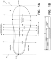
- Fig. 1A also provides information that may be useful for explaining and understanding the specification and/or aspects of this technology.
- Fig. 1A provides a representation of a footwear/foot-receiving device component 100, which in this illustrated example constitutes a portion of a sole structure for an article of footwear.
- the same general definitions and terminology described below may apply to footwear and foot-receiving devices in general and/or to other footwear/foot-receiving device components or portions thereof, such as an upper, a midsole component, an outsole component, a sole structure, etc.
- the rearmost heel location RH and the forwardmost toe location FT may be located by determining the rear heel and forward toe tangent points with respect to front and back parallel vertical planes VP when the component 100 (e.g., sole structure or foot-supporting member in this illustrated example, optionally as part of an article of footwear or foot-receiving device) is oriented on a horizontal support surface S in an unloaded condition (e.g., with no weight applied to it other than potentially the weight of the shoe/foot-receiving device components with which it is engaged).
- component 100 e.g., sole structure or foot-supporting member in this illustrated example, optionally as part of an article of footwear or foot-receiving device
- the forwardmost and/or rearmost locations of a specific footwear or foot-receiving device component 100 constitute a line segment (rather than a tangent point), then the forwardmost toe location and/or the rearmost heel location constitute the mid-point of the corresponding line segment. If the forwardmost and/or rearmost locations of a specific footwear or foot-receiving device component 100 constitute two or more separated points or line segments, then the forwardmost toe location and/or the rearmost heel location constitute the mid-point of a line segment connecting the furthest spaced and separated points and/or furthest spaced and separated end points of the line segments (irrespective of whether the midpoint itself lies on the component 100 structure). If the forwardmost and/or rearwardmost locations constitute one or more areas, then the forwardmost toe location and/or the rearwardmost heel location constitute the geographic center of the area or combined areas (irrespective of whether the geographic center itself lies on the component 100 structure).
- slat means a thin, narrow strip of a foot support component extending across and forming a portion of a base support surface of the foot support component.
- a “slat” will have a thickness dimension "T” (e.g., in a foot support component/footwear top-to-bottom direction), a width dimension "W” (e.g., a direct dimension across the component from one open space to an opposite and adjacent open space-in some examples, a dimension in the foot support component's heel-to-toe direction and/or in the sole structure's/footwear's longitudinal direction), and a breadth dimension "B” (e.g., transverse to the width dimension-in some examples, a dimension in the foot support component's lateral side-to-medial side direction and/or in the sole structure's/footwear's transverse direction).
- T thickness dimension
- W e.g., a direct dimension across the component from one open space to an opposite and adjacent open space-in some examples, a dimension in the
- central area of a foot support member or slat means a central 35% to 65% of the foot support member or slat in its longest dimension B (e.g., in some examples, this longest dimension of the member/slat will be a breadth dimension and/or in the lateral side-to-medial side direction of the foot support member or slat).
- Foot support members/slats defined by openings or open spaces that originate within the sidewall fall within the scope of the term "originate at or proximate to,” unless the phrase is further modified to expressly state that the foot support member/slat originates in the base support surface.
- the phrase "located at or proximate to” similarly means that any portions of the noted items (e.g., an "origination point" and a "sidewall”) are within 20 mm of one another (and in some examples, when stated, may be within 15 mm, within 10 mm, within 5 mm, or even contacting).
- a foot support member/slat may originate (have an "origination point") at a location "spaced away" from a free edge of a sidewall by a direct distance of at least 2 mm, and in some examples, by at least 3 mm, at least 5 mm, at least 10 mm, or even at least 15 mm.
- Foot support components for articles of footwear include: (a) a lateral sidewall that extends to and forms a lateral free edge (e.g., a lateral top edge); (b) a medial sidewall located opposite the lateral sidewall, wherein the medial sidewall extends to and forms a medial free edge (e.g., a medial top edge); and (c) a base support surface that includes an exterior surface and an interior surface opposite the exterior surface.
- the base support surface includes a plurality of foot support members (i.e. arched foot support slats) for supporting at least a portion of the plantar surface of a wearer's foot.
- the base support surface includes: (a) a first arched foot support slat, wherein a local extrema (e.g., a peak of the arch) of the first arched foot support slat is located in a central area of the first arched foot support slat between the lateral sidewall and the medial sidewall, and wherein the first arched foot support slat originates at or proximate to the lateral sidewall and the medial sidewall at respective locations spaced away from the lateral free edge and the medial free edge, (b) a second arched foot support slat, wherein a local extrema (e.g., a peak of the arch) of the second arched foot support slat is located in a central area of the second arched foot support slat between the lateral sidewall and the medial sidewall, and wherein the second arched foot support slat originates at or proximate to the lateral sidewall and the medial sidewall at respective locations space
- Foot support components for articles of footwear in accordance with the claimed invention include: (a) a lateral sidewall that extends to and forms a lateral free edge (e.g., lateral top edge); (b) a medial sidewall located opposite the lateral sidewall, wherein the medial sidewall extends to and forms a medial free edge (e.g., medial top edge); and (c) a base support surface that includes an exterior surface and an interior surface opposite the exterior surface.
- the base support surface includes a plurality of foot support members (i.e., arched foot support slats) for supporting at least a portion of the plantar surface of a wearer's foot.
- a majority, or even all-of the foot support members may include: (i) a lateral end point located at or proximate to the lateral sidewall, (ii) a medial end point located at or proximate to the medial sidewall, (iii) a forward edge defined at least in part by a forward open space located between the foot support member and a forwardly adjacent foot support member, (iv) a rearward edge defined at least in part by a rearward open space located between the foot support member and a rearwardly adjacent foot support member, and (v) a single local extrema (for that arched foot support member) located in a central area of the arched foot support member between the lateral sidewall and the medial sidewall.
- the base support surface may include:
- the forward edge of one foot support member may be separated from the rearward edge of the forwardly adjacent foot support member over at least 75%, at least 80%, at least 90%, at least 95%, or even at least 98% of the breadth dimensions of either or both of the noted foot support members.
- one or more additional arched foot support members having any one or more of the features of the first, second, and third arched foot support members, may be included (e.g., arranged forward and/or rearward of the first, second, and third arched foot support members) in the base support surface and/or foot support component without departing from this technology.
- the base support surface may include:
- Additional aspects of this technology relate to more specific features of the various footwear components described above and described in more detail below as well as additional features or structures included in the footwear components.
- Such additional aspects may include: more specific features of a footwear component including the lateral and medial sidewalls and the base support surface, e.g., features of a connecting wall (e.g., a rear heel wall, a forward toe wall); features of connecting the above footwear component with other footwear components, such as foam midsole components, bladder midsole components, other midsole components, outsole components, footwear upper components, etc.; various dimensional features of the footwear components; etc.
- a connecting wall e.g., a rear heel wall, a forward toe wall
- features of connecting the above footwear component with other footwear components such as foam midsole components, bladder midsole components, other midsole components, outsole components, footwear upper components, etc.
- various dimensional features of the footwear components etc.
- the article of footwear 200 of Fig. 2A includes an upper 202 and a sole structure 204 engaged with the upper 202.
- foot support components 250 in accordance with aspects of this technology may constitute all or a portion of the sole structure 204.
- the upper 202 and sole structure 204 may be engaged together in any desired manner, including in manners conventionally known and used in the footwear arts (such as by one or more of adhesives or cements, stitching or sewing, mechanical connectors, etc.).
- the upper 202 potentially together with the sole structure 204, define a foot-receiving interior chamber 206 for containing a wearer's foot.
- the bottom of the upper 202 may include a strobel 208 or other component engaged with or integrally formed with another portion of the upper 202 e.g., a lateral side upper component 202L and/or a medial side upper component 202M.
- the upper 202 may include other components as well.
- the upper 202 may include: a tongue member located across the foot instep area and positioned to moderate the feel of the footwear's closure system on the wearer's foot; a closure system (e.g., including one or more of a lace type closure system, a zippered closure system, a buckle type closure system, elastic stretch elements, etc.); a heel counter; a toe cap; straps; etc.
- the upper 202 may include a "sock-like" upper component, e.g., made from fabric and configured to closely fit the wearer's foot like a conventional sock.
- the upper 202 may be made from any desired material(s) and/or in any desired constructions and/or manners without departing from this technology. As some more specific examples, all or at least a portion of the upper 202 (and optionally a majority, substantially all, or even all of the upper 202) may be formed as a woven textile component, a knitted textile component, another textile component, a natural leather component, a synthetic leather component, a polymeric component (e.g., a TPU, etc.), etc.
- the components for upper 202 may have structures and/or constructions like those used in footwear products commercially available from NIKE, Inc. of Beaverton, OR and/or other manufacturers.
- uppers 202 and articles of footwear 200 in accordance with at least some examples of this technology may include fused layers of upper materials, e.g., uppers of the types that include upper materials bonded by hot melt or other adhesive materials, such as in footwear products commercially available from NIKE, Inc. of Beaverton, Oregon.
- uppers of the types described in U.S. Patent Nos. 7,347,011 and/or 8,429,835 may be used without departing from this technology.
- FIG. 2A shows the top surface 252T of outsole component 252 having a generally planar surface
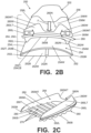
- Fig. 2B shows an alternative in which the top surface 252T is contoured (e.g., upwardly arched in the lateral side-to-medial side direction).
- the open space 252O of outsole component 252 may define a horizontal cross sectional area between side arms 252L and 252M of at least 10 cm 2 , and in some examples at least 15 cm 2 , at least 20 cm 2 , at least 25 cm 2 , at least 30 cm 2 , at least 40 cm 2 , at least 50 cm 2 , or even at least 60 cm 2 (this area may be measured as the horizontal cross-sectional area of the opening 252O with the outsole component 252 supported on its ground-facing surface on a horizontal base surface in an unloaded condition (e.g., without weight applied to the outsole component 252, other than perhaps the weight of other components making up the foot support component 250, sole structure 204, and/or article of footwear)).
- this area may be measured as the horizontal cross-sectional area of the opening 252O with the outsole component 252 supported on its ground-facing surface on a horizontal base surface in an unloaded condition (e.g., without weight applied to the outsole component 252, other than perhaps the weight of other components making up
- the lower midsole component 254 includes an intermediate recess or central open space 254O between a lateral side arm 254L and a medial side arm 254M, as well as a rear connecting wall 254W connecting the lateral side arm 254L and the medial side arm 254M.
- the lower midsole component 254 may have a generally U-shape, including a generally U-shaped outer perimeter and a generally U-shaped inner perimeter (and the lower midsole component 254 may terminate, e.g., in a midfoot area or heel area of the sole structure 204, at lateral free end 254LE and medial free end 254LM).
- the central open space (e.g., 254O) of lower midsole component 254 also could be provided, if desired, by a generally oval, round, or elliptically shaped lower midsole component, by a rounded rectangular shaped lower midsole component, by another open ended or close ended lower midsole configuration, and/or by providing separate medial and lateral side components (e.g., omitting connecting wall 254W), etc.
- the open space 254O may have any desired shape as well.
- Foot support component 250 of this example includes an upper midsole component 256, e.g., located closest to the wearer's foot in this illustrated example.
- this upper midsole component 256 may be located directly beneath, and in some examples directly engaged with, the upper 202 (e.g., with the bottom surface, such as a strobel 208, of the upper 202).
- the upper midsole component 256 of this example includes a top surface 256T engaged with the bottom surface of the upper 202 (e.g., strobel 208). Any desired manner of engagement between upper midsole component 256 and upper 202 may be employed without departing from this technology, including fixed or releasable connections.
- these components 202/256 may be engaged together via one or more of: cements or adhesives; mechanical fasteners or hardware; fused or welded connections; etc.
- the upper midsole component 256 of this example includes a bottom surface 256B engaged with the top surface 260T of the midsole component 260 (which is described in more detail below). Any desired manner of engagement between upper midsole component 256 and midsole component 260 may be employed without departing from this technology, including fixed or releasable connections.
- these components 256/260 may be engaged together via one or more of: cements or adhesives; mechanical fasteners or hardware; fused or welded connections; etc.
- the lower midsole component 254 may be "firmer” than the upper midsole component 256. This may be determined, for example, by determining which component responds with greater deflection under an applied force or load (e.g., with the "firmer” component vertically displacing or deflecting less than the vertical displacement or deflection of the "softer" component under the same applied force conditions).
- the upper midsole component 256 has a lateral side wall 256L and a medial side wall 256M, as well as a rear wall 256W connecting the lateral side wall 256L and the medial side wall 256M.
- the upper midsole component 256 may have a half-oval or a half-elliptical shape, e.g., including a generally U-shaped outer perimeter.
- This example upper midsole component 256 terminates, e.g., in a midfoot area or heel area of the sole structure 204, at free end 256E.
- the midsole component 260 (which itself may be considered a "foot support component” or a portion thereof in accordance with the claimed invention) now will be described in more detail in conjunction with Figs. 2A-2J .
- This midsole component 260 may constitute a one piece or multi-piece construction, e.g., made from rigid plastic material(s), such as a thermoplastic polyurethane (“TPU”) material; a polyether block amide thermoplastic elastic polymer material (e.g., available under the PEBAX ® brand (from Arkema) and/or VESTAMID ® E brand (from Evonik)); a fiber-reinforced composite plastic component (e.g., carbon fiber reinforced composite, glass fiber reinforced composite, etc.); etc.
- TPU thermoplastic polyurethane
- PEBAX ® brand from Arkema
- VESTAMID ® E brand from Evonik
- fiber-reinforced composite plastic component e.g., carbon fiber reinforced composite, glass fiber reinforced composite, etc.
- the material making up the midsole component may be a rigid plastic material having a Shore D hardness within a range of 20 to 80 Shore D, and in some examples, between 25 and 80, between 30 and 80, between 35 and 80, between 40 and 75, or even between 50 and 75 Shore D.
- a foot support component 250 and/or midsole component 260 has at least 3 individual arched foot support members/slats 270; optionally (a) at least 5 individual arched foot support members/slats 270; (b) from 3 to 45 individual arched foot support members/slats 270; (c) from 3 to 35 individual arched foot support members/slats 270; (d) from 3 to 25 individual arched foot support members/slats 270; (e) from 3 to 20 individual arched foot support members/slats 270; (f) from 3 to 16 individual arched foot support members/slats 270; (g) from 3 to 12 individual arched foot support members/slats 270; and or (h) from 3 to 8 individual arched foot support members/slats 270.
- one or more of the foot support members/slats 270 may be planar, substantially planar, or unarched (e.g., planar, substantially planar, or unarched when in an unloaded condition and oriented on a horizontal support surface with its ground-facing surface oriented downward), as long as at least three foot support members are arched.
- At least three, optionally a majority, or even all of the individual foot support members/slats 270 of a foot support component 250/midsole component 260 extend in a generally lateral side-to-medial side direction of the sole structure 204/article of footwear 200, i.e., originating at or proximate to the lateral sidewall 260L and/or the medial side-wall 260M. As shown in Figs.
- At least three, optionally a majority, or even all of the individual foot support members/slats 270 of a foot support component 250/midsole component 260 originate at locations spaced away from the lateral free edge 260LT and/or at locations spaced away from the medial free edge 260MT.
- the open space(s) 280 are positioned and shaped to completely separate at least 90% of a rearward edge 270RE of one arched foot support member/slat 270 from at least 90% of a forward edge 270FE of a rearwardly adjacent arched foot support member/slat 270. See Fig. 2J .
- the open space(s) 280 may be positioned and shaped to completely separate at least 95%, at least 98%, or even 100% of a rearward edge 270RE of one arched foot support member/slat 270 from at least 95%, at least 98%, or even 100% of a forward edge 270FE of a rearwardly adjacent arched foot support member/slat 270.
- These spaces 280 shape and/or member/slat 270 separation features may be provided between any number of adjacent foot support member/slat 270 pairs in the overall midsole component 260 structure.
- the foot support member/slat 270's width dimension W2 will correspond to the distance from a foot support member/slat 270's forward edge 270FE to its rear edge 270RE across the foot support member/slat 270 and perpendicular to the breadth dimension B2. If the width of the foot support member/slat 270 varies over the breadth dimension B2, then the width dimension W2 may be considered as the widest width dimension present across the foot support member/slat 270 that is perpendicular to the breadth dimension B2.
- open space 280's breadth dimension B1 and/or foot support member/slat 270's breadth dimension B2 may have one or more of the following properties: (a) at least 15 mm long, (b) at least 20 mm long, (c) at least 30 mm long, (d) at least 40 mm long, (e) at least 50 mm long, (f) less than 150 mm long, (g) less than 120 mm long, (h) less than 100 mm long, (i) less than 90 mm long, (j) from 15 mm to 150 mm long, (k) from 18 mm to 120 mm long, (1) from 20 mm to 100 mm long, (m) from 25 mm to 90 mm long, and/or (n) from 30 mm to 85 mm long.
- the ratios of B1/W1 and/or B2/W2 may be within one or more of the ranges of: (a) 0.5 to 150, (b) 0.75 to 120, (c) 1 to 100, (d) 1 to 80, (e) 1 to 60, (f) 1.25 to 50, (g) 1.5 to 40, (h) 1.5 to 40, (i) 1.75 to 25, (i) 2 to 20, (j) 2.2 to 18, and/or (k) 2.3 to 15.
- the ratio of W1 to W2 may be within one or more of the ranges of: (a) 0.05 to 5, (b) 0.1 to 3, (c) 0.15 to 2, (d) 0.2 to 1.8, (e) 0.25 to 1.5; and/or (f) 0.5 to 1.25.
- the wall height dimension HW or vertical height may be up to 50 mm or even more, particularly in examples in which the midsole component's sidewall(s) 260L, 260M, and/or 260W may provide functions of a footwear heel counter.
- the open spaces 280 and foot support members/slats 270 may be structured and arranged such that the forward edge 270FE of one or more of the individual foot support members/slats 270 will be substantially parallel to the rearward edge 270RE of a forwardly adjacent foot support member/slat 270 over at least 75%, at least 80%, at least 85%, at least 90%, at least 95%, or even 100% of one or both of the adjacent foot support members/slats 270 longest dimensions and/or edge lengths.
- the "forward edge" 270FE and the "rearward edge” 270RE of an individual foot support member/slat 270 may be found by: (a) extending a lateral end line 282L from the outermost lateral location of the forward open space 280 to the outermost lateral location of the rearward open space 280 that define the individual foot support member/slat 270 and (b) extending a medial end line 282M from the outermost medial location of the forward open space 280 to the outermost medial location of the rearward open space 280 that define the individual foot support member/slat 270.
- the relevant edges 270FE, 270RE, 280FE, 280RE begin/end where the end lines 282L, 282M reach the open spaces 280 defining the foot support member/slat 270.
- the longest or breadth dimension of the open space 280 (B1) is the dimension from 280LE to 280ME.
- the longest or breadth dimension of the foot support member/slat 270 (B2) may be measured from the lateral midpoint (270LMP) of lateral end line 282L to the medial midpoint (270MMP) of the medial end line 282M. See Fig. 2J .
- At least one of the arched foot support members/slats 270 may include: (i) a lateral origination point 270LE and/or a lateral end or midpoint 270LMP located at or proximate to the lateral sidewall 260L, (ii) a medial origination point 270ME and/or a medial end or midpoint 270MMP located at or proximate to the medial sidewall 260M, (iii) a forward edge 270FE extending from a forward lateral origination point 270LE to a corresponding forward medial origination point 270ME, (iv) a rearward edge 270RE extending from an adjacent rearward lateral origination point 270LE to a corresponding adjacent rearward medial origination point 270ME, and (v) a single local extrema 270E for that arched foot support member/slat 270
- FIGs. 2A-2J illustrate foot support members/slats 270 and spaces 280 having substantially constant dimensions and parallel orientations within an individual midsole component 260
- the sizes, shapes, dimensions, orientations, and/or other features of the foot support members/slats 270 and/or spaces 280 may be varied within an individual midsole component 260. These features also may be varied, e.g., for customization/optimization purposes, as will be described in more detail below.
- Some examples include: including one or more hinge structures (e.g., in the connecting wall 260W and/or within the breadth dimension of one or more foot support members/slats 270); including a compressible material as part of the connecting wall 260W and/or within the breadth dimension of one or more foot support members/slats 270; providing one or more gaps in the connecting wall 260W and/or within the breadth dimension of one or more foot support members/slats 270; providing one or more perforated areas and/or predefined bend lines in the connecting wall 260W and/or within the breadth dimension of one or more foot support members/slats 270; etc.
- hinge structures e.g., in the connecting wall 260W and/or within the breadth dimension of one or more foot support members/slats 270
- a compressible material as part of the connecting wall 260W and/or within the breadth dimension of one or more foot support members/slats 270
- Such structures may promote bending in one direction while resisting bending in the opposite direction (at least resisting bending in the opposite direction once the sole structure 204/foot support component 250/midsole component 260 returns to its unbent or preloaded condition (e.g., after the force from landing the step or jump is removed or sufficiently reduced)).
- the connecting wall 260W may constitute a forward toe wall and be located in the forefoot area (e.g., the extreme forward toe area) of a sole structure 204/foot support component 250/midsole component 260.
- Some sole structures 204/foot support components 250/midsole components 260 in accordance with this technology may include connecting walls 260W at both the rear heel area and the forward toe area of the structure. In such examples with two connecting walls 260W, either or both or neither of the connecting walls 260W may include a notched area 260N and/or other pre-defined bend features of the types described above.
- the exterior surface 260B of the base support surface 260S includes: (a) a lateral base edge 262L (e.g., a lower lateral base edge) located on an opposite side of the lateral sidewall 260L from the lateral free edge 260LT, (b) a medial base edge 262M (e.g., a lower medial base edge) located on an opposite side of the medial sidewall 260M from the medial free edge 260MT, and (c) a connecting base edge 262W (e.g., a lower edge) located on an opposite side of the connecting wall 260W from the connecting wall free edge 260WT.
- a lateral base edge 262L e.g., a lower lateral base edge
- medial base edge 262M e.g., a lower medial base edge
- a connecting base edge 262W e.g., a lower edge
- the lower midsole component 254 has a U-shaped structure in which the lateral base edge 254LB and the lateral sidewall 254L of the lower midsole component 254 form a lateral arm of the U-shaped structure, the medial base edge 254MB and the medial sidewall 254M of the lower midsole component 254 form a medial arm of the U-shaped structure, and the connecting base edge 254CB and the connecting wall 254W of the lower midsole component form a base of the U-shaped structure (connecting the above-noted medial and lateral side edges and sidewalls).
- the U-shaped structure of the lower midsole component 254 defines an open space 254O between the lateral arm (and lateral sidewall 254L) and the medial arm (and medial sidewall 254M).
- the article of footwear 200/sole structure 204/foot support component 250 of this example may include an outsole system 252.
- the outsole system 252 may comprise one or more outsole components including a surface structured and arranged to contact the ground (or other contact surface) in use (e.g., when worn by a wearer).
- At least some examples of this technology will attenuate impact forces, e.g., by compressing the midsole components 254, 256 and/or vertically displacing the foot support members/slats 270 of the midsole component 260.
- the foot support component 250/midsole component 260 may apply a securing force to the wearer's foot.
- a downward force F e.g., from landing a step or jump
- one or more of the foot support members 270 e.g., upwardly arched foot support members/slats 270
- Figs. 3A-3C illustrate an example assembly process of sole structures 204/foot support components 250 in accordance with at least some examples of this technology.
- the process may start with up to four components of the sole structures 204/foot support components 250, e.g., a first midsole component or system (e.g., lower midsole component 254 in this example), a second midsole component or system (e.g., upper midsole component 256 in this example), a foot support component or system (e.g., midsole component 260 in this example), and an outsole component or system (e.g., outsole component 252 in this example).
- a first midsole component or system e.g., lower midsole component 254 in this example
- a second midsole component or system e.g., upper midsole component 256 in this example
- a foot support component or system e.g., midsole component 260 in this example
- an outsole component or system e.g., outsole component 252 in this example.
- the outsole component 252 may hold the first midsole component 254 with the second midsole component 256 without the first midsole component 254 being directly fixed to the second midsole component 256.
- the first midsole component 254 may be readily movable with respect to the second midsole component 256, e.g., as shown in Fig. 3B .
- a recess 300 may be defined between the bottom surface 256B of the second midsole component 256 and the top surface 254T of the first midsole component 254 at this stage.
- the various sole components 252, 254, 256, and/or 260 may be engaged together (and/or with other sole components, upper components, and/or footwear components) in different orders and/or in different manners.
- the midsole component 260 first may be engaged with one of first midsole component 254 or second midsole component 256, (b) then that combination may be engaged with the other midsole component (254 or 256), and (c) then that combination may be engaged with the outsole component 252.
- These engagements may be fixed or releasable, and may include any one or more of adhesives, mechanical connectors, and/or fuse bonded/welded joints.
- the bottom surface 256B of the second midsole component 256 may include one or more ribs 256R or other structures that fit within the space(s) 280 provided between adjacent foot support members/slats 270 of the midsole component 260.
- the rib(s) 256R may help engage the second midsole component 256 with the midsole component 260, help prevent undesired relative movement between these two components 256, 260, and/or help prevent undesired deflection of the foot support members/slats 270 in the heel-to-toe direction of the sole structure 204/foot support component 250.
- This example sole structure 204/foot support component 250 assembly process (as well as other assembly processes that incorporate a foot support component like foot support member 260 into the sole structure 204/foot support component 250) provide opportunities for customization or otherwise tailoring footwear and foot support to a specific wearer and/or to a specific use (e.g., specific sports, specific activities, specific team positions, etc.).
- plantar forces produced by a footwear wearer may be measured (e.g., using foot force measuring systems as are known and used in the art), e.g., with the wearer involved in some type of activity in which a step or jump is landed and/or other forces are applied by the wearer's foot to a contact surface and forces are applied by the contact surface to the wearer's foot.
- Fig. 3D provides a bottom view of an assembled sole structure 204/foot support component 250 in accordance with some examples of this technology.
- the first midsole system 254 e.g., the lower midsole component 254
- the first midsole system 254 may be substantially U-shaped, having free ends 254LE, 254ME of the U-shape located in the heel or midfoot region of the sole structure 204/foot support component 250 and a central open space 254O.
- the forward extent of the first midsole system 254 in this illustrated example is shown by broken line 310 in Fig. 3D .
- this specific example as described above in conjunction with Figs.
- the outsole component 252 may include an intermediate recess or central open space 252O, e.g., between a lateral side arm 252L and a medial side arm 252M.
- the outsole component 252 may include a closed front end to close off the intermediate recess or central open space 252O, as shown by outsole portion 252F in Fig. 3D .
- the remainder of the bottom of the sole structure 204/foot support component 250 of this example (around and forward of the open spaces 252O, 254O and the line 310) constitutes the bottom surface 252B of the outsole 252.
- sole structures 204/foot support components 250 in which an outsole opening 252O and a lower midsole component opening 254O at least partially align e.g., as shown in Fig. 3D
- at least a portion of one or more of the foot support members/slats 270 may be exposed at the exterior of the final assembled sole structure 204 and the final assembled foot support component 250.
- the bottom surface 256B of the second (upper) midsole component 256 may be exposed in one or more of the spaces 280 between adjacent foot support members/slats 270.
- each of the foot support members/slats 270 extends continuously from its lateral origination point 270LE to its medial origination point 270ME (and/or from its lateral end or midpoint 270LMP to its medial end or midpoint 270MMP), and each of the spaces 280 extends continuously from its lateral end 280LE to its medial end 280ME.
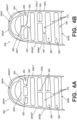
- Fig. 4A provides an alternative example of a foot support component in the form of a midsole component 360 similar to those described above for midsole component 260.
- one or more bridge components 362 may be located outside the central area of the foot support members/slats 270 and/or positioned away from one or both of the local extrema 270E of two adjacent arched foot support members/slats 270. Also, as shown in Fig. 4A , two adjacent foot support members/slats 270 may be connected by more than one bridge components 362.
- the bridge component(s) 362 may be integrally formed as part of the midsole component 360 (e.g., when the midsole component 360 is molded) and may be made of the same material as the midsole component 360 (or a different material).
- one or more bridge components 362 may be separate parts engaged with two or more adjacent foot support members/slats 270 (e.g., by adhesives or cements, mechanical connectors, fusing techniques, etc.).
- one or more gaps 462 may be located outside the central area of the foot support members/slats 270 and/or positioned away from the local extrema 270E of an arched foot support member/slat 270.
- the gap(s) 462 may be integrally formed as part of the midsole component 460 (e.g., when the midsole component 460 is molded) and/or they may be cut across the foot support member/slat 270 after it is formed.
- the term "gap" as used herein in this context may constitute a discontinuity in foot support member/slat 270 (having little or no measurable separation).
- Fig. 4B shows gaps 462 connecting four pair of adjacent spaces 280
- any number of gaps 462 may be included in an individual midsole component 460 connecting any number of pair of adjacent spaces 280.
- an individual midsole component 460 may include one or more gaps 462 and one or more bridge components 362, e.g., of the types described above in conjunction with Fig. 4A .
- the midsole component 260 of the foot support component 250 and the sole structure 204 is located primarily in a heel region of the article of footwear, although other options are mentioned.
- the midsole component 260, 360, 460 of the example of Fig. 6 may include a lateral sidewall (e.g., like 260L), a medial sidewall (e.g., like 260M), a receptacle, and a slatted or other base surface 260S of the types described above.
- a substantial connecting wall (akin to wall 260W) may be omitted which is not in accordance with the claimed invention, e.g., to avoid a raised wall running across the plantar surface of a wearer's foot.
- One or both of the outsole component 252 and/or the lower midsole component 254 may include central openings 252O, 254O, if desired, so that the bottom 260B of the midsole component 260, 360, 460 (e.g., the foot support member(s)/slat(s) 270 and/or space(s) 280) are exposed at the bottom exterior of the overall sole structure 204, as shown in Fig. 6 .
- the sidewall height dimension(s) HW may be somewhat toward the lower end of the various ranges described above (e.g., less than 15 mm high, less than 12 mm high, less than 10 mm high, etc.).
- Portions of the bottom surface 260B of the midsole component 260, 360, 460 at the rearwardmost extent and/or around the periphery thereof may be covered by the lower midsole component 254 and/or the outsole component 252 in at least some examples of this forefoot based structure.
- This example midsole component 260, 360, 460 may include a lateral sidewall (e.g., like 260L), a medial sidewall (e.g., like 260M), a receptacle, and a slatted or other base surface 260S of the types described above.
- a forward connecting wall (akin to wall 260W) may be located around the forward toe area of the structure to connect the lateral sidewall 260L and the medial sidewall 260M.
- This forward connecting wall may have any of the structural features, properties, options, and the like of the connecting wall 260W described above, including the notch features and/or other prebend/flexion supporting features, except that it is located around the front of the foot support structure rather than around the rear of the structure.
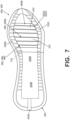
- One or both of the outsole component 252 and/or the lower midsole component 254 may include central openings 252O, 254O, if desired (and may be U-shaped), so that the bottom 260B of the midsole component 260, 360, 460 (e.g., the foot support member(s)/slat(s) 270 and/or space(s) 280) are exposed at the bottom exterior of the overall sole structure 204, as shown in Fig. 7 .
Landscapes
- Health & Medical Sciences (AREA)
- Epidemiology (AREA)
- General Health & Medical Sciences (AREA)
- Public Health (AREA)
- Footwear And Its Accessory, Manufacturing Method And Apparatuses (AREA)
Description
- This application claims priority benefits based on
U.S. Provisional Patent Appln. No. 62/905,649 filed September 25, 2019 - The present technology relates to the field of footwear. More specifically, aspects of the present technology pertain to foot support components for articles of footwear.
- Conventional articles of athletic footwear include two primary elements, an upper and a sole structure. The upper provides a covering for the foot that securely receives and positions the foot with respect to the sole structure. In addition, the upper may have a configuration that protects the foot and provides ventilation, thereby cooling the foot and removing perspiration. The sole structure is secured to a lower surface of the upper and is generally positioned between the foot and any contact surface. In addition to attenuating ground reaction forces and absorbing energy, the sole structure may provide traction and control potentially harmful foot motion, such as over pronation. General features and configurations of uppers and sole structures are discussed in greater detail below.
- The upper forms a void on the interior of the footwear for receiving the foot. The void has the general shape of the foot, and access to the void is provided at an ankle or foot-insertion opening. Accordingly, the upper extends over the instep and toe areas of the foot, along the medial and lateral sides of the foot, and around the heel area of the foot. A lacing system often is incorporated into the upper to selectively change the size of the ankle opening and to permit the wearer to modify certain dimensions of the upper, particularly girth, to accommodate feet with varying proportions. In addition, the upper may include a tongue that extends under the lacing system to enhance the comfort of the footwear (e.g., to modulate pressure applied to the foot by the laces), and the upper also may include a heel counter to limit or control movement of the heel.
- The sole structure generally incorporates multiple layers that are conventionally referred to as an "insole," a "midsole," and an "outsole." The insole (which also may constitute a sock liner) is a thin member located within the upper and adjacent the plantar (lower) surface of the foot to enhance footwear comfort, e.g., to wick away moisture. The midsole, which is traditionally attached to the upper along the upper's entire length, forms the middle layer of the sole structure and serves a variety of purposes that include controlling foot motions and attenuating impact forces. The outsole forms the ground-contacting element of footwear and usually is fashioned from a durable, wear-resistant material that includes texturing or other features to improve traction.
- The primary element of a conventional midsole is a resilient, polymer foam material, such as polyurethane or ethylvinylacetate ("EVA"), that extends throughout the length of the footwear. The properties of the polymer foam material in the midsole are primarily dependent upon factors that include the dimensional configuration of the midsole and the specific characteristics of the material selected for the polymer foam, including the density of the polymer foam material. By varying these factors throughout the midsole, the relative stiffness, the degree of ground reaction force attenuation, and the energy absorption properties may be altered to meet the specific demands of the activity for which the footwear is intended to be used.
-
US 5 337 492 A discloses a shoe bottom, in particular for sports shoes. -
US 2017/251750 A1 describes an article of footwear with an external support member. -
US 2005/132610 A1 relates to an article of footwear having a fluid-filled bladder with a reinforcing structure. - Some general terminology and information is provided that will assist in understanding various portions of this specification and the claimed invention as described herein. As noted above, the present technology relates to the field of footwear, but it also may relate to other foot-receiving devices. "Foot-receiving device" means any device into which a user places at least some portion of his or her foot. In addition to all types of footwear (described below), foot-receiving devices include, but are not limited to: bindings and other devices for securing feet in snow skis, cross country skis, water skis, snowboards, and the like; bindings, clips, or other devices for securing feet in pedals for use with bicycles, exercise equipment, and the like; bindings, clips, or other devices for receiving feet during play of video games or other games; and the like. "Foot-receiving devices" may include: (a) one or more "foot-covering members" (e.g., akin to footwear upper components), which help position the foot with respect to other components or structures and (b) one or more "foot-supporting members" or foot-support components" (e.g., akin to footwear sole structures and components thereof), which support at least some portion(s) of a plantar surface of a user's foot. "Footwear" means any type of wearing apparel for the feet, and this term includes, but is not limited to: all types of shoes, boots, sneakers, sandals, thongs, flip-flops, mules, scuffs, slippers, sport-specific shoes (such as golf shoes, tennis shoes, baseball cleats, soccer or football cleats, ski boots, basketball shoes, cross training shoes, track shoes, track field event shoes (e.g., for high jump, triple jump, etc.), etc.), and the like. "Foot-supporting members" may include components for and/or functioning as midsoles and/or outsoles for articles of footwear (or components providing corresponding functions in non-footwear type foot-receiving devices).
-
Fig. 1A also provides information that may be useful for explaining and understanding the specification and/or aspects of this technology.Fig. 1A provides a representation of a footwear/foot-receivingdevice component 100, which in this illustrated example constitutes a portion of a sole structure for an article of footwear. The same general definitions and terminology described below may apply to footwear and foot-receiving devices in general and/or to other footwear/foot-receiving device components or portions thereof, such as an upper, a midsole component, an outsole component, a sole structure, etc. - First, as illustrated in
Fig. 1A , the terms "forward" or "forward direction" as used herein, unless otherwise noted or clear from the context, mean toward or in a direction toward a forward-most toe area FT of the footwear or foot-receiving device structure orcomponent 100. The terms "rearward" or "rearward direction" as used herein, unless otherwise noted or clear from the context, mean toward or in a direction toward a rear-most heel area RH of the footwear or foot-receiving device structure orcomponent 100. The terms "lateral" or "lateral side" as used herein, unless otherwise noted or clear from the context, mean the outside or "little toe" side of the footwear or foot-receiving device structure orcomponent 100. The terms "medial" or "medial side" as used herein, unless otherwise noted or clear from the context, mean the inside or "big toe" side of the footwear or foot-receiving device structure orcomponent 100. - Also, various example features and aspects of this technology are disclosed or explained herein with reference to a "longitudinal direction" and/or with respect to a "longitudinal length" L of a footwear/foot-receiving device component 100 (such as a footwear sole structure). As shown in
Fig. 1A , the "longitudinal direction" is determined as the direction of a line extending from a rearmost heel location (RH inFig. 1A ) to the forwardmost toe location (FT inFig. 1A ) of thefootwear component 100 in question (a sole structure or foot-supporting member in this illustrated example). The "longitudinal length" L is the length dimension measured from the rearmost heel location RH to the forwardmost toe location FT. The rearmost heel location RH and the forwardmost toe location FT may be located by determining the rear heel and forward toe tangent points with respect to front and back parallel vertical planes VP when the component 100 (e.g., sole structure or foot-supporting member in this illustrated example, optionally as part of an article of footwear or foot-receiving device) is oriented on a horizontal support surface S in an unloaded condition (e.g., with no weight applied to it other than potentially the weight of the shoe/foot-receiving device components with which it is engaged). If the forwardmost and/or rearmost locations of a specific footwear or foot-receiving device component 100 constitute a line segment (rather than a tangent point), then the forwardmost toe location and/or the rearmost heel location constitute the mid-point of the corresponding line segment. If the forwardmost and/or rearmost locations of a specific footwear or foot-receivingdevice component 100 constitute two or more separated points or line segments, then the forwardmost toe location and/or the rearmost heel location constitute the mid-point of a line segment connecting the furthest spaced and separated points and/or furthest spaced and separated end points of the line segments (irrespective of whether the midpoint itself lies on thecomponent 100 structure). If the forwardmost and/or rearwardmost locations constitute one or more areas, then the forwardmost toe location and/or the rearwardmost heel location constitute the geographic center of the area or combined areas (irrespective of whether the geographic center itself lies on thecomponent 100 structure). - Once the longitudinal direction of a component or
structure 100 has been determined with thecomponent 100 oriented on a horizontal support surface S, planes may be oriented perpendicular to this longitudinal direction (e.g., planes running into and out of the page ofFig. 1A ). The locations of these perpendicular planes may be specified based on their positions along the longitudinal length L where the perpendicular plane intersects the longitudinal direction between the rearmost heel location RH and the forwardmost toe location FT. In this illustrated example ofFig. 1A , the rearmost heel location RH is considered as the origin for measurements (or the "0L position") and the forwardmost toe location FT is considered the end of the longitudinal length L of this component (or the "1.0L position"). Plane position may be specified based on its location along the longitudinal length L (between 0L and 1.0L), measured forward from the rearmost heel RH location in this example.Fig. 1A further shows locations of various planes perpendicular to the longitudinal direction (and oriented in the transverse direction) and located along the longitudinal length L at positions 0.25L, 0.4L, 0.5L, 0.55L, 0.6L, and 0.8L (measured in a forward direction from the rearmost heel location RH). These planes may extend into and out of the page of the paper from the view shown inFig. 1A , and similar planes may be oriented at any other desired positions along the longitudinal length L. While these planes may be parallel to the parallel vertical planes VP used to determine the rearmost heel RH and forwardmost toe FT locations, this is not a requirement. Rather, the orientations of the perpendicular planes along the longitudinal length L will depend on the orientation of the longitudinal direction, which may or may not be parallel to the horizontal surface S in the arrangement/orientation shown inFig. 1A . The "transverse direction" shown inFig. 1A also is perpendicular to the longitudinal direction (and optionally, in at least some instances, may extend along the direction of the horizontal surface S). - The term "slat," as used herein, unless otherwise defined or clear from the context, means a thin, narrow strip of a foot support component extending across and forming a portion of a base support surface of the foot support component. In at least some examples, a "slat" will have a thickness dimension "T" (e.g., in a foot support component/footwear top-to-bottom direction), a width dimension "W" (e.g., a direct dimension across the component from one open space to an opposite and adjacent open space-in some examples, a dimension in the foot support component's heel-to-toe direction and/or in the sole structure's/footwear's longitudinal direction), and a breadth dimension "B" (e.g., transverse to the width dimension-in some examples, a dimension in the foot support component's lateral side-to-medial side direction and/or in the sole structure's/footwear's transverse direction). In some examples of this technology, a "slat" may have any one or more of the following features: (a) T = 0.01W to 0.6W; (b) T = 0.025W to 0.5W; (c) T = 0.05W to 0.45W; (d) T = 0.075W to 0.35W; (e) W = 0.01B to 0.4B; (f) W = 0.02B to 0.35B; (g) W = 0.03B to 0.3B; and/or (h) W = 0.05B to 0.25B. While "slats" may have a generally rectangular shape or may be formed as a rectangular prism, "slats" as that term is used herein may have one or more rounded corners and/or edges. "Slats" also may have curved edges in any dimension (including curved edges in one or more of the thickness direction, the width direction, and/or the breadth dimension).
- The term "extrema" as used herein, unless otherwise defined or clear from the context, means a point of inflection of a curved or arched surface. With respect to foot support members and/or slats as described herein, an "extrema" corresponds to the peak of the curved surface when the foot support member, sole structure, and/or article of footwear is supported on its ground-facing surface on a horizontal support surface, e.g., in an unloaded condition (e.g., with no external forces applied thereto except for forces holding the foot support member, sole structure, and/or article of footwear together).
- The term "central area" of a foot support member or slat, as used herein, unless otherwise defined or clear from the context, means a central 35% to 65% of the foot support member or slat in its longest dimension B (e.g., in some examples, this longest dimension of the member/slat will be a breadth dimension and/or in the lateral side-to-medial side direction of the foot support member or slat). If a foot support member or slat is considered to have a longest dimension B in one direction (e.g., from its lateral end point to its medial end point), the "central 35% to 65%" or "central area" of that foot support member or slat means the region located from 0.35B to 0.65B measured from either side's origin point. See the shaded area of
Fig. 1B . - The phrase "originates at or proximate to" as used herein, unless otherwise noted or clear from the context, means the location of the opening or open space defining an outer extreme of a foot support member/slat in the breadth dimension B (the outer point of the opening or open space that defines an edge of the foot support member/slat) directly at or within 20 mm of any portion of the corresponding sidewall of the component. In some examples, the foot support member/slat will originate (have an "origination point") within 15 mm, within 10 mm, or even within 5 mm, of the corresponding sidewall. Foot support members/slats defined by openings or open spaces that originate within the sidewall fall within the scope of the term "originate at or proximate to," unless the phrase is further modified to expressly state that the foot support member/slat originates in the base support surface. The phrase "located at or proximate to" similarly means that any portions of the noted items (e.g., an "origination point" and a "sidewall") are within 20 mm of one another (and in some examples, when stated, may be within 15 mm, within 10 mm, within 5 mm, or even contacting).
- The term "spaced away" as used herein, unless otherwise noted or clear from the context, means that at least some measurable distance exists between the noted components. In some more specific examples, if specifically noted, a foot support member/slat may originate (have an "origination point") at a location "spaced away" from a free edge of a sidewall by a direct distance of at least 2 mm, and in some examples, by at least 3 mm, at least 5 mm, at least 10 mm, or even at least 15 mm. Additionally or alternatively, in at least some examples, a distance or dimension (e.g., a sidewall height dimension or other direct distance measurement) of at least 2 mm (and in some examples, at least 3 mm, at least 5 mm, at least 10 mm, or even at least 15 mm) may exist between: (a) an outer extreme of a foot support member/slat in the breadth dimension B (the outer point of the opening or open space defining an edge of the foot support member/slat) and (b) the free (e.g., top) edge of the corresponding sidewall.
- The term "substantially parallel" as used herein, unless otherwise noted or clear from the context, means that the two items (e.g., two edges of foot support members/slats, two edges of an opening defining foot support members/slats, etc.): (a) are parallel (i.e., are separated by a constant distance), (b) are separated by a "substantially constant distance "d" (i.e., d ± 10%) over at least 85% of at least one of the item's dimension (e.g., at least one edge's breadth dimension), and/or (c) extend in directions (e.g., breadth dimension directions) that do not intersect (e.g., within the base support surface) and are at an angle of less than 10 degree from one another. Edges that directly intersect one another (e.g., within the base support surface) are not "substantially parallel" irrespective of their angles with respect to one another. Edges need not be straight lines to be "substantially parallel."
- The term "majority" as used herein, means any amount "more than 50%." The phrase "foot support member/slat" as used herein (including its plural variation) means "foot support member and/or slat."
- Foot support components include plural arched foot support members (e.g., arched slats) forming at least a portion of a footbed for a sole structure/article of footwear. Spacings between individual foot support members enable selective activation of one or more individual members, thereby providing support where needed and enhancing overall comfort without overly stiffening the footbed. When made from sufficiently rigid/resilient materials, the foot support components may bend (e.g., flatten) under an applied force and then apply return energy to the wearer's foot by springing back to and/or toward their original shape when the force sufficiently abates/relaxes.
- The foregoing Summary, as well as the following Detailed Description, will be better understood when read in conjunction with the accompanying drawings in which like reference numerals refer to the same or similar elements in all of the various views in which that reference number appears.
-
Figs. 1A and 1B are provided to help illustrate and explain background and definitional information useful for understanding certain terminology used in this application and certain aspects of this technology; -
Fig. 2A and2B provide an exploded view and a rear heel view of a heel area and/or heel components of foot support components, sole structures, and/or articles of footwear in accordance with some examples of this technology; -
Fig. 2C provides a perspective view of an example foot support component (or portion thereof) in accordance with some examples of this technology; -
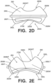
Fig. 2D provides a rear view of an example foot support component (or portion thereof) in accordance with some examples of this technology; -
Fig. 2E provides a front view of an example foot support component (or portion thereof) in accordance with some examples of this technology; -
Figs. 2F and 2G provide medial side and lateral side views, respectively, of an example foot support component (or portion thereof) in accordance with some examples of this technology; -
Figs. 2H and 2I provide top and bottom views, respectively, of an example foot support component (or portion thereof) in accordance with some examples of this technology; -
Fig. 2J provides an enlarged view of a portion of a foot support component in accordance with some examples of this technology; -
Figs. 3A-3D illustrate examples of a footwear sole structure and assembly thereof in accordance with some examples of this technology; -
Fig. 4A illustrates an example foot support component (or portion thereof) including foot support members joined in their central areas and/or other areas; -
Fig. 4B illustrates an example foot support component (or portion thereof) including foot support members having a discontinuity in their central areas and/or other areas; -
Fig. 5 provides an exploded view of a heel area and/or heel components of another example of foot support components and/or sole structures in accordance with some examples of this technology; -
Fig. 6 illustrates an example of a midfoot/arch located foot support component in accordance with some examples of this technology; -
Fig. 7 illustrates an example of a forefoot located foot support component in accordance with some examples of this technology; and -
Fig. 8 illustrates an example of a full foot support component in accordance with some examples of this technology. - The reader should understand that the attached drawings are not necessarily drawn to scale.
- In the following description of various examples of footwear and foot-receiving device structures and components according to the present technology, reference is made to the accompanying drawings, which form a part hereof, and in which are shown by way of illustration various example structures and environments in which aspects of the claimed invention may be practiced. It is to be understood that other structures and environments may be utilized and that structural and functional modifications may be made from the specifically described structures and functions.
- Referring to the figures and following discussion, various foot support components, articles of footwear, and features thereof in accordance with aspects of the claimed invention are disclosed. Concepts disclosed with respect to these components and footwear may be applied to a wide range of athletic footwear styles, including, but not limited to: walking shoes, tennis shoes, soccer shoes, football shoes, basketball shoes, running shoes, track shoes, shoes for track field events (e.g., high jump, triple jump, etc.), cross-training shoes, etc. In addition, the concepts of the claimed invention may be applied to a wide range of non-athletic footwear, including work boots, sandals, loafers, and dress shoes. The invention is defined by the appended
independent claim 1. Additional embodiments are defined in the dependent claims. - Foot support components for articles of footwear according to this technology include: (a) a lateral sidewall that extends to and forms a lateral free edge (e.g., a lateral top edge); (b) a medial sidewall located opposite the lateral sidewall, wherein the medial sidewall extends to and forms a medial free edge (e.g., a medial top edge); and (c) a base support surface that includes an exterior surface and an interior surface opposite the exterior surface. The base support surface includes a plurality of foot support members (i.e. arched foot support slats) for supporting at least a portion of the plantar surface of a wearer's foot. Since arched, at least three-and in some examples, a majority, or even all-of the foot support members constitute an arched foot support slat, wherein a local extrema (e.g., a peak of the arch) of the arched foot support member (slat) is located in a central area of the arched foot support member (slat) between the lateral sidewall and the medial sidewall. The arched foot support member(s)/slat(s) originate(s) at or proximate to the lateral sidewall and/or at or proximate to the medial sidewall at locations spaced away from the lateral free edge and the medial free edge. In the claimed invention, at least three of the arched foot support members/slats are separated from one another by open spaces, i.e., spaces that extend between (e.g., continuously and completely) and separate at least 90% of a rearward edge of one arched foot support component/slat from at least 90% of a forward edge of an adjacent arched foot support component/slat. In still other example structures, the spaces may extend (e.g., continuously and completely) to separate at least 95%, or even at least 98% of a rearward edge of one arched foot support component/slat from at least 95%, or even at least 98% of a forward edge of an adjacent arched foot support component/slat.
- According to the present invention, the base support surface includes: (a) a first arched foot support slat, wherein a local extrema (e.g., a peak of the arch) of the first arched foot support slat is located in a central area of the first arched foot support slat between the lateral sidewall and the medial sidewall, and wherein the first arched foot support slat originates at or proximate to the lateral sidewall and the medial sidewall at respective locations spaced away from the lateral free edge and the medial free edge, (b) a second arched foot support slat, wherein a local extrema (e.g., a peak of the arch) of the second arched foot support slat is located in a central area of the second arched foot support slat between the lateral sidewall and the medial sidewall, and wherein the second arched foot support slat originates at or proximate to the lateral sidewall and the medial sidewall at respective locations spaced away from the lateral free edge and the medial free edge, (c) a third arched foot support slat, wherein a local extrema (e.g., a peak of the arch) of the third arched foot support slat is located in a central area of the third arched foot support slat between the lateral sidewall and the medial sidewall, and wherein the third arched foot support slat originates at or proximate to the lateral sidewall and the medial sidewall at respective locations spaced away from the lateral free edge and the medial free edge, (d) a first open space extending between (e.g., continuously and completely) and separating at least 90% of a rearward edge of the first arched foot support slat from at least 90% of a forward edge of the second arched foot support slat, and (e) a second open space extending between (e.g., continuously and completely) and separating at least 90% of a rearward edge the second arched foot support slat from at least 90% of a forward edge of the third arched foot support slat. In some example structures, the first open space and/or the second open space may extend to continuously and completely separate at least 95%, or even at least 98% of a rearward edge of one arched foot support component/slat from at least 95%, or even at least 98% of a forward edge of an adjacent arched foot support component/slat. In the claimed invention, each of the first open space and the second open space constitutes a through hole extending completely through the base support surface from the exterior surface of the base support surface to the interior surface of the base support surface.
- Foot support components for articles of footwear in accordance with the claimed invention include: (a) a lateral sidewall that extends to and forms a lateral free edge (e.g., lateral top edge); (b) a medial sidewall located opposite the lateral sidewall, wherein the medial sidewall extends to and forms a medial free edge (e.g., medial top edge); and (c) a base support surface that includes an exterior surface and an interior surface opposite the exterior surface. The base support surface includes a plurality of foot support members (i.e., arched foot support slats) for supporting at least a portion of the plantar surface of a wearer's foot. Since arched, at least three-and in some examples, a majority, or even all-of the foot support members may include a forward edge extending between: (i) a first lateral origination point located at or proximate to the lateral sidewall and (ii) a first medial origination point located at or proximate to the medial sidewall, and a rearward edge extending between: (i) a second lateral origination point located at or proximate to the lateral sidewall and (ii) a second medial origination point located at or proximate to the medial sidewall, and wherein one or more of the arched foot support members further include a single local extrema (for that arched foot support member) located in a central area of the arched foot support member between the lateral sidewall and the medial sidewall. Additionally or alternatively, since arched, at least three-and in some examples, a majority, or even all-of the foot support members may include: (i) a lateral end point located at or proximate to the lateral sidewall, (ii) a medial end point located at or proximate to the medial sidewall, (iii) a forward edge defined at least in part by a forward open space located between the foot support member and a forwardly adjacent foot support member, (iv) a rearward edge defined at least in part by a rearward open space located between the foot support member and a rearwardly adjacent foot support member, and (v) a single local extrema (for that arched foot support member) located in a central area of the arched foot support member between the lateral sidewall and the medial sidewall. In any of these examples, the forward edge of one foot support member may be substantially parallel with the rearward edge of a forwardly adjacent foot support member, and/or the forward edge of the one foot support member may be separated from the rearward edge of the forwardly adjacent foot support member over at least 85% of a breadth dimension of the noted forward edge (or over at least 85% of a breadth dimension of the rearward foot support member) and/or over at least 85% of a breadth dimension of the noted rearward edge (or over at least 85% of a breadth dimension of the forward foot support member). In some examples, the forward edge of the one foot support member may be separated from the rearward edge of the forwardly adjacent foot support member over at least 75%, at least 80%, at least 90%, at least 95%, or even at least 98% of the breadth dimensions of either or both of the noted foot support members. In such examples, one or more of the support members may be continuous and separated from one another over their entire breadth(s), one or more of the support members may be discontinuous in their lateral side-to-medial side breadth dimension (e.g., have a gap therein), and/or one or more of the support members may be joined to one or both adjacent support members, e.g., by bridging material extending or crossing over the space between adjacent support members.
- As some more specific examples of these aspects of the technology, the base support surface may include:
- (a) a first arched foot support member that includes: (i) a first lateral end point located at or proximate to the lateral sidewall, (ii) a first medial end point located at or proximate to the medial sidewall, (iii) a first forward edge defined at least in part by a first open space, (iv) a first rearward edge defined at least in part by a second open space, and (v) a single local extrema for the first arched foot support member located in a central area of the first arched foot support member between the lateral sidewall and the medial sidewall,
- (b) a second arched foot support member that includes: (i) a second lateral end point located at or proximate to the lateral sidewall, (ii) a second medial end point located at or proximate to the medial sidewall, (iii) a second forward edge defined at least in part by the second open space, (iv) a second rearward edge defined at least in part by a third open space, and (v) a single local extrema for the second arched foot support member located in a central area of the second arched foot support member between the lateral sidewall and the medial sidewall, wherein the second forward edge is substantially parallel with the first rearward edge, and wherein the second forward edge is separated from the first rearward edge: (1) over at least 85% of a breadth dimension of the second arched foot support member, and/or (2) over at least 85% of a breadth dimension of the first arched foot support member, and
- (c) a third arched foot support member that includes: (i) a third lateral end point located at or proximate to the lateral sidewall, (ii) a third medial end point located at or proximate to the medial sidewall, (iii) a third forward edge defined at least in part by the third open space, (iv) a third rearward edge defined at least in part by a fourth open space, and (v) a single local extrema for the third arched foot support member located in a central area of the third arched foot support member between the lateral sidewall and the medial sidewall, wherein the third forward edge is substantially parallel with the second rearward edge, and wherein the third forward edge is separated from the second rearward edge: (1) over at least 85% of a breadth dimension of the third arched foot support member, and/or (2) over at least 85% of a breadth dimension of the second arched foot support members.
- In these examples, the forward edge of one foot support member may be separated from the rearward edge of the forwardly adjacent foot support member over at least 75%, at least 80%, at least 90%, at least 95%, or even at least 98% of the breadth dimensions of either or both of the noted foot support members. Further, one or more additional arched foot support members, having any one or more of the features of the first, second, and third arched foot support members, may be included (e.g., arranged forward and/or rearward of the first, second, and third arched foot support members) in the base support surface and/or foot support component without departing from this technology.
- Additionally or alternative, as some more specific examples, the base support surface may include:
- (a) a first arched foot support member that includes a first forward edge extending between: (i) a first lateral origination point located at or proximate to the lateral sidewall and (ii) a first medial origination point located at or proximate to the medial sidewall and a first rearward edge extending between: (i) a second lateral origination point located at or proximate to the lateral sidewall and (ii) a second medial origination point located at or proximate to the medial sidewall, and wherein the first arched foot support member includes a first single local extrema located in a central area of the first arched foot support member between the lateral sidewall and the medial sidewall,
- (b) a second arched foot support member that includes a second forward edge extending between: (i) a third lateral origination point located at or proximate to the lateral sidewall and (ii) a third medial origination point located at or proximate to the medial sidewall and a second rearward edge extending between: (i) a fourth lateral origination point located at or proximate to the lateral sidewall and (ii) a fourth medial origination point located at or proximate to the medial sidewall, and wherein the second arched foot support member includes a second single local extrema located in a central area of the second arched foot support member between the lateral sidewall and the medial sidewall, wherein the second forward edge is substantially parallel with the first rearward edge, and wherein the second forward edge is separated from the first rearward edge over at least 85% of a breadth dimension of the second arched foot support member, and
- (c) a third arched foot support member that includes a third forward edge extending between: (i) a fifth lateral origination point located at or proximate to the lateral sidewall and (ii) a fifth medial origination point located at or proximate to the medial sidewall and a third rearward edge extending between: (i) a sixth lateral origination point located at or proximate to the lateral sidewall and (ii) a sixth medial origination point located at or proximate to the medial sidewall, and wherein the third arched foot support member includes a third single local extrema located in a central area of the third arched foot support member between the lateral sidewall and the medial sidewall, wherein the third forward edge is substantially parallel with the second rearward edge, and wherein the third forward edge is separated from the second rearward edge over at least 85% of a breadth dimension of the third arched foot support member.
- In these examples, the forward edge of one foot support member may be separated from the rearward edge of the forwardly adjacent foot support member over at least 75%, at least 80%, at least 90%, at least 95%, or even at least 98% of the breadth dimensions of either or both of the noted foot support members. Further, one or more additional arched foot support members, having any one or more of the features of the first, second, and third arched foot support members, may be included (e.g., arranged forward and/or rearward of the first, second, and third arched foot support members) in the base support surface and/or foot support component without departing from this technology.
- Additional aspects of this technology relate to more specific features of the various footwear components described above and described in more detail below as well as additional features or structures included in the footwear components. Such additional aspects may include: more specific features of a footwear component including the lateral and medial sidewalls and the base support surface, e.g., features of a connecting wall (e.g., a rear heel wall, a forward toe wall); features of connecting the above footwear component with other footwear components, such as foam midsole components, bladder midsole components, other midsole components, outsole components, footwear upper components, etc.; various dimensional features of the footwear components; etc. These additional aspects of the technology may be included as part of any of the individual examples and aspects of the technology described in the paragraphs above.
- Still additional aspects of this technology, not forming part of the claimed invention, relate to methods of making footwear components and/or articles of footwear containing them, e.g., of the types and having the structures described above (and described in more detail below).
- Given the above background and general description of aspects and examples of this technology, a more detailed description of specific examples of articles of footwear in accordance with at least some examples of this technology and the claimed invention follows.
-
Figs. 2A-2J show various views offoot support components 250 and articles offootwear 200 containingfoot support components 250 in accordance with at least some aspects of this technology. The term "foot support component" as used herein may include any one or more foot support parts, e.g., forming the entirety and/or a portion of a sole structure for an article offootwear 200. Such "foot support components" may include, for example, any individual part and/or combination of two or more foot support parts shown in the example ofFigs. 2A-2J . Various features, characteristics, and/or parts of example articles offootwear 200 andfoot support components 250 thereof are described in more detail below. - The article of
footwear 200 ofFig. 2A includes an upper 202 and asole structure 204 engaged with the upper 202. As noted above,foot support components 250 in accordance with aspects of this technology may constitute all or a portion of thesole structure 204. The upper 202 andsole structure 204 may be engaged together in any desired manner, including in manners conventionally known and used in the footwear arts (such as by one or more of adhesives or cements, stitching or sewing, mechanical connectors, etc.). - The upper 202, potentially together with the
sole structure 204, define a foot-receivinginterior chamber 206 for containing a wearer's foot. The bottom of the upper 202 may include astrobel 208 or other component engaged with or integrally formed with another portion of the upper 202 e.g., a lateral sideupper component 202L and/or a medial sideupper component 202M. The upper 202 may include other components as well. For example, the upper 202 may include: a tongue member located across the foot instep area and positioned to moderate the feel of the footwear's closure system on the wearer's foot; a closure system (e.g., including one or more of a lace type closure system, a zippered closure system, a buckle type closure system, elastic stretch elements, etc.); a heel counter; a toe cap; straps; etc. Additionally or alternatively, the upper 202 may include a "sock-like" upper component, e.g., made from fabric and configured to closely fit the wearer's foot like a conventional sock. - The upper 202 may be made from any desired material(s) and/or in any desired constructions and/or manners without departing from this technology. As some more specific examples, all or at least a portion of the upper 202 (and optionally a majority, substantially all, or even all of the upper 202) may be formed as a woven textile component, a knitted textile component, another textile component, a natural leather component, a synthetic leather component, a polymeric component (e.g., a TPU, etc.), etc. The components for upper 202 may have structures and/or constructions like those used in footwear products commercially available from NIKE, Inc. of Beaverton, OR and/or other manufacturers.
- Additionally or alternatively, if desired, the upper 202 construction may include uppers having foot securing and engaging structures (e.g., "dynamic" and/or "adaptive fit" structures), e.g., of the types described in
U.S. Patent Appln. Publn. No. 2013/0104423 . As some additional examples, if desired, uppers and articles of footwear in accordance with this technology may include foot securing and engaging structures of the types used in footwear products commercially available from NIKE, Inc. of Beaverton, Oregon. These types of wrap-around and/or adaptive or dynamic fit structures may at least partially wrap around, conform to, and/or securely hold the wearer's foot. - As yet another alternative or additional feature, if desired,
uppers 202 and articles offootwear 200 in accordance with at least some examples of this technology may include fused layers of upper materials, e.g., uppers of the types that include upper materials bonded by hot melt or other adhesive materials, such as in footwear products commercially available from NIKE, Inc. of Beaverton, Oregon. As still additional examples, uppers of the types described inU.S. Patent Nos. 7,347,011 and/or 8,429,835 may be used without departing from this technology. - The example
foot support components 250 shown inFigs. 2A and2B now will be described in more detail.Fig. 2A shows an exploded perspective view of an examplefoot support component 250 andFig. 2B provides an assembled rear view of afoot support component 250. As illustrated in these figures, this example footwearsole structure 204 and/orfoot support component 250 includes: (a) anoutsole component 252; (b) a lower midsole component 254 (also called a "first midsole component" or a "first midsole system" herein); (c) an upper midsole component 256 (also called a "second midsole component" or a "second midsole system" herein); and (d) an intermediate midsole component 260 (also called a "foot support component" or a "midsole component" herein) at least partially located between thelower midsole component 254 and theupper midsole component 256. Various example structures, features, and/or characteristics of these various footwearsole structures 204 and/orfoot support components 250/parts are described in more detail below. -
Outsole component 252 of this examplesole structure 204/foot support component 250 may have any desired structure, function, and/or characteristics and may be made from any desired material(s) without departing from this technology, including conventional structures, functions, characteristics and/or materials as are known and used in the footwear arts. As some more specific examples,outsole component 252 may be formed from rubber, polymeric materials, or the like. Thebottom surface 252B thereof may include traction elements, treads, cleats, spikes, and/or any other desired configurations, including any conventional configuration for sport specific uses. Theoutsole component 252 may include wear resistant/abrasion resistant materials and may be designed to contact the ground or other contact surface in use. While other shapes are possible, in these illustrated examples, theoutsole component 252 includes an intermediate recess or central open space 252O between alateral side arm 252L and amedial side arm 252M, as well as arear connecting wall 252W connecting thelateral side arm 252L and themedial side arm 252M. Thus, in this manner, theoutsole component 252 may have a generally U-shape, including a generally U-shaped outer perimeter and a generally U-shaped inner perimeter (and theoutsole component 252 may terminate, e.g., in a midfoot area or heel area of thesole structure 204, at lateral free end 252LE and medial free end 252LM). WhileFig. 2A shows thetop surface 252T ofoutsole component 252 having a generally planar surface,Fig. 2B shows an alternative in which thetop surface 252T is contoured (e.g., upwardly arched in the lateral side-to-medial side direction). - The U-shape of
outsole component 252 is not a requirement in all aspects of this technology, although some type of central open space may be advantageous in accordance with at least some examples of this technology. For example, the central open space (e.g., 252O) ofoutsole component 252 may enhance flexibility between the lateral side and medial side of thesole structure 204, e.g., promoting/enhancing natural motion. Also, the central open space (e.g., 252O) can provide room for vertical displacement of other components of thefoot support component 250, e.g., in response to a foot force (e.g., landing a step or jump), as will be described in more detail below. The central open space (e.g., 252O) ofoutsole component 252 also could be provided, if desired, by a generally round, oval, or elliptically shaped outsole component, by a rounded rectangular shaped outsole component, by another open ended or close ended outsole configuration, and/or by providing separate medial and lateral side components (e.g., omitting connectingwall 252W), etc. The open space 252O may have any desired shape as well. In at least some examples of the claimed invention, the open space 252O ofoutsole component 252 may define a horizontal cross sectional area betweenside arms outsole component 252 supported on its ground-facing surface on a horizontal base surface in an unloaded condition (e.g., without weight applied to theoutsole component 252, other than perhaps the weight of other components making up thefoot support component 250,sole structure 204, and/or article of footwear)). - The
outsole component 252 in this examplefoot support component 250 structure is engaged with alower midsole component 254. In this illustrated example,lower midsole component 254 includes abottom surface 254B engaged with thetop surface 252T of theoutsole component 252. Any desired manner of engagement betweenlower midsole component 254 andoutsole component 252 may be employed without departing from this technology, including fixed or releasable connections. As some more specific examples, thesecomponents 252/254 may be engaged together via one or more of: cements or adhesives; mechanical fasteners or hardware; fused or welded connections; etc. - The
lower midsole component 254 of this example attenuates impact forces (e.g., when a wearer's foot contacts a surface when landing a step or jump) and may have any desired constructions and/or number of parts without departing from this technology (including conventional constructions and/or parts as are known and used in the footwear arts). In some more specific examples, thelower midsole component 254 may include one or more of: (a) a foam material and/or one or more foam components; (b) one or more fluid-filled bladders; (c) one or more mechanical shock absorbing components; etc. - While other shapes are possible, in the illustrated examples of
Figs. 2A and2B , thelower midsole component 254 includes an intermediate recess or central open space 254O between alateral side arm 254L and amedial side arm 254M, as well as arear connecting wall 254W connecting thelateral side arm 254L and themedial side arm 254M. Thus, in this manner, thelower midsole component 254 may have a generally U-shape, including a generally U-shaped outer perimeter and a generally U-shaped inner perimeter (and thelower midsole component 254 may terminate, e.g., in a midfoot area or heel area of thesole structure 204, at lateral free end 254LE and medial free end 254LM). - The U-shape of
lower midsole component 254 is not a requirement in all aspects of this technology, although some type of central open space may be advantageous in accordance with at least some examples of this technology. For example, the central open space (e.g., 254O) oflower midsole component 254 may enhance flexibility between the lateral side and medial side of thesole structure 204, (e.g., promoting/enhancing natural motion). Also, the central open space (e.g., 254O) can provide room for vertical displacement of other components of thefoot support component 250, e.g., in response to a foot force (e.g., landing a step or jump), as will be described in more detail below. The central open space (e.g., 254O) oflower midsole component 254 also could be provided, if desired, by a generally oval, round, or elliptically shaped lower midsole component, by a rounded rectangular shaped lower midsole component, by another open ended or close ended lower midsole configuration, and/or by providing separate medial and lateral side components (e.g., omitting connectingwall 254W), etc. The open space 254O may have any desired shape as well. In at least some examples of the claimed invention, the open space 254O ofmidsole component 254 may define a horizontal cross sectional area betweenside arms foot support component 250,sole structure 204, and/or article offootwear 204 supported on its ground-facing surface on a horizontal base surface in an unloaded condition (e.g., without weight applied to themidsole component 254, other than perhaps the weight of other components making up thefoot support component 250,sole structure 204, and/or article of footwear)). -
Foot support component 250 of this example includes anupper midsole component 256, e.g., located closest to the wearer's foot in this illustrated example. In some examples, thisupper midsole component 256 may be located directly beneath, and in some examples directly engaged with, the upper 202 (e.g., with the bottom surface, such as astrobel 208, of the upper 202). Thus, theupper midsole component 256 of this example includes atop surface 256T engaged with the bottom surface of the upper 202 (e.g., strobel 208). Any desired manner of engagement betweenupper midsole component 256 and upper 202 may be employed without departing from this technology, including fixed or releasable connections. As some more specific examples, thesecomponents 202/256 may be engaged together via one or more of: cements or adhesives; mechanical fasteners or hardware; fused or welded connections; etc. Also, theupper midsole component 256 of this example includes abottom surface 256B engaged with thetop surface 260T of the midsole component 260 (which is described in more detail below). Any desired manner of engagement betweenupper midsole component 256 andmidsole component 260 may be employed without departing from this technology, including fixed or releasable connections. As some more specific examples, thesecomponents 256/260 may be engaged together via one or more of: cements or adhesives; mechanical fasteners or hardware; fused or welded connections; etc. - The
upper midsole component 256 attenuates impact forces (e.g., when a wearer's foot contacts a surface when landing a step or jump) and/or provides a comfortable base surface for engaging at least a portion of the wearer's foot. Thisupper midsole component 256 may have any desired constructions and/or number of parts without departing from this technology (including conventional constructions and/or parts as are known and used in the footwear arts). In some more specific examples, theupper midsole component 256 may include one or more of: (a) a foam material and/or one or more foam components; (b) one or more fluid-filled bladders; (c) one or more mechanical shock absorbing components; etc. In at least some examples offoot support components 250 in accordance with aspects of this technology, when both anupper midsole component 256 and alower midsole component 254 are present, thelower midsole component 254 may be "firmer" than theupper midsole component 256. This may be determined, for example, by determining which component responds with greater deflection under an applied force or load (e.g., with the "firmer" component vertically displacing or deflecting less than the vertical displacement or deflection of the "softer" component under the same applied force conditions). When bothcomponents 254/256 are made from and/or include a foam material, the "firmer" component may be considered as the foam material having a greater hardness property (e.g., greatest durometer or hardness on a Shore A scale) and/or greater density and the "softer" component may be considered as the foam material having a lower hardness property (e.g., lower durometer or hardness on a Shore A scale) and/or lower density. In some more specific examples, theupper midsole component 256 may be made from a foam material that is at least 10 Shore A hardness points lower than the foam material of the lower midsole component 254 (and in some examples, at least 15 points, at least 20 points, at least 25 points, at least 30 points, or even at least 35 points lower on the Shore A scale). - While other shapes are possible, in the illustrated examples of
Figs. 2A and2B , theupper midsole component 256 has alateral side wall 256L and amedial side wall 256M, as well as arear wall 256W connecting thelateral side wall 256L and themedial side wall 256M. Theupper midsole component 256 may have a half-oval or a half-elliptical shape, e.g., including a generally U-shaped outer perimeter. This exampleupper midsole component 256 terminates, e.g., in a midfoot area or heel area of thesole structure 204, atfree end 256E. - The midsole component 260 (which itself may be considered a "foot support component" or a portion thereof in accordance with the claimed invention) now will be described in more detail in conjunction with
Figs. 2A-2J . Thismidsole component 260 may constitute a one piece or multi-piece construction, e.g., made from rigid plastic material(s), such as a thermoplastic polyurethane ("TPU") material; a polyether block amide thermoplastic elastic polymer material (e.g., available under the PEBAX® brand (from Arkema) and/or VESTAMID®E brand (from Evonik)); a fiber-reinforced composite plastic component (e.g., carbon fiber reinforced composite, glass fiber reinforced composite, etc.); etc. In some examples, themidsole component 260 will be formed as a rigid, yet flexible and resilient construction, e.g., capable of deforming or deflecting under an applied force (e.g., from a wearer landing a step or jump or otherwise applying foot force), but resiliently returning to its original shape when the applied force is sufficiently relaxed or reduced. In some examples, themidsole component 260 may be considered to include a "plate" like base structure (e.g., a relatively thin base surface, and in some examples formed from a plurality of "slat" type members extending across the midsole component 260 (and, if present, across an open space defined by open area(s) 254O and/or 252O)). The material making up the midsole component may be a rigid plastic material having a Shore D hardness within a range of 20 to 80 Shore D, and in some examples, between 25 and 80, between 30 and 80, between 35 and 80, between 40 and 75, or even between 50 and 75 Shore D. - As shown in
Figs. 2A-2J , themidsole component 260 of this examplefoot support component 250 includes: (a) alateral sidewall 260L that extends to and forms a lateral free edge (260LT - lateral top edge); (b) amedial sidewall 260M located opposite thelateral sidewall 260L that extends to and forms a medial free edge (260MT - medial top edge); and (c) abase support surface 260S that includes an exterior surface (260B - bottom surface) and an interior surface (260T - top surface) opposite theexterior surface 260B. Thebase support surface 260S of this illustrated example includes a plurality of archedfoot support members 270, whereof at least three take on the form of arched foot support slats (e.g., upwardly arched when in an unloaded condition and oriented on a horizontal support surface with its ground-facing surface oriented downward). The individual arched foot support members/slats 270 in a singlefoot support component 250 may have the same size and/or shape features as other individual arched foot support members/slats 270 or one or more arched foot support members/slats 270 may have a different size and/or shape in one or more dimensions than at least one other arched foot support members/slats 270 in that samefoot support component 250 and/ormidsole component 260. - A
foot support component 250 and/ormidsole component 260 has at least 3 individual arched foot support members/slats 270; optionally (a) at least 5 individual arched foot support members/slats 270; (b) from 3 to 45 individual arched foot support members/slats 270; (c) from 3 to 35 individual arched foot support members/slats 270; (d) from 3 to 25 individual arched foot support members/slats 270; (e) from 3 to 20 individual arched foot support members/slats 270; (f) from 3 to 16 individual arched foot support members/slats 270; (g) from 3 to 12 individual arched foot support members/slats 270; and or (h) from 3 to 8 individual arched foot support members/slats 270. Rather than arched foot support members/slats 270, one or more of the foot support members/slats 270 may be planar, substantially planar, or unarched (e.g., planar, substantially planar, or unarched when in an unloaded condition and oriented on a horizontal support surface with its ground-facing surface oriented downward), as long as at least three foot support members are arched. - In foot support components 250 (including in the illustrated
midsole component 260 of this example) according to this technology, at least three individual arched foot support member/slat 270 will include alocal extrema 270E, e.g., a single inflection point or peak of the arch/curve of the individual arched foot support member/slat 270 (seeFigs. 2D and 2E ). In some examples of this technology: (a) a majority of the individual foot support members/slats 270 of thefoot support component 250/midsole component 260 will include the arched/curved shape andlocal extrema 270E features, or even (b) all of the individual foot support members/slats 270 of thefoot support component 250/midsole component 260 will include the arched/curved shape andlocal extrema 270E features. Additionally or alternatively, a plurality, or a majority of the foot support members/slats 270 in amidsole component 260 may have a planar (flat) surface or a substantially planar surface, as long as at least three foot support members are arched. - According to the claimed invention, at least three, optionally a majority, or even all of the individual foot support members/
slats 270 of afoot support component 250/midsole component 260 extend in a generally lateral side-to-medial side direction of thesole structure 204/article offootwear 200, i.e., originating at or proximate to thelateral sidewall 260L and/or the medial side-wall 260M. As shown inFigs. 2A and2C , at least three, optionally a majority, or even all of the individual foot support members/slats 270 of afoot support component 250/midsole component 260 originate at locations spaced away from the lateral free edge 260LT and/or at locations spaced away from the medial free edge 260MT. -
Figs. 2D and 2E further illustrate that thelocal extrema 270E of at least three individual arched foot support member/slat 270 (and, in some examples, at least a majority, or even all of the individual arched foot support members/slats 270) is located in a central area of that arched foot support member/slat 270 (i.e., within the central 35% to 65% of the arched foot support member/slat 270 in its longest dimension B (in its breadth dimension in this illustrated example)). As some additional examples, if desired, thelocal extrema 270E of at least one individual arched foot support member/slat 270 (and, in some examples, at least a plurality, at least a majority, or even all of the individual arched foot support members/slats 270) may be located within the central 40% to 60% of the arched foot support member/slat 270 in its longest dimension B (e.g., in its breadth dimension) or even within the central 45% to 55% of the arched foot support member/slat 270 in its longest dimension B (e.g., in its breadth dimension). - As further shown in this illustrated example (e.g.,
Figs. 2A ,2C ,2H-2J ), the individual arched foot support members/slats 270 are separated from one another byopen spaces 280, e.g., openings extending completely through themidsole component 260 of this example (e.g., from itstop surface 260T to itsbottom surface 260B). As shown inFigs. 2H-2J , at least two open spaces 280 (and in some examples, a majority of theopen spaces 280, or even all of the open spaces 280) extend continuously to at least partially separate one arched foot support member/slat 270 from an adjacent arched foot support member/slat 270. The open space(s) 280 are positioned and shaped to completely separate at least 90% of a rearward edge 270RE of one arched foot support member/slat 270 from at least 90% of a forward edge 270FE of a rearwardly adjacent arched foot support member/slat 270. SeeFig. 2J . In some examples, the open space(s) 280 may be positioned and shaped to completely separate at least 95%, at least 98%, or even 100% of a rearward edge 270RE of one arched foot support member/slat 270 from at least 95%, at least 98%, or even 100% of a forward edge 270FE of a rearwardly adjacent arched foot support member/slat 270. Thesespaces 280 shape and/or member/slat 270 separation features may be provided between any number of adjacent foot support member/slat 270 pairs in theoverall midsole component 260 structure. -
Fig. 2J illustrates various dimensional features of open spaces 280 (e.g., breadth dimension B1, width dimension W1) and foot support members/slats 270 (e.g., breadth dimension B2, width dimension W2) inmidsole components 260 in accordance with at least some examples of the claimed invention. The breadth dimensions B1, B2 may be the longest dimensions of theopen space 280 and foot support member/slat 270, respectively, e.g., a lateral side-to-medial side dimension. The width dimensions W1, W2 may be transverse to their corresponding breadth dimension B1, B2, respectively, e.g., a heel-to-toe dimension. - For generally rectangular shaped
spaces 280 and/or foot support members/slats 270, determining the dimensions B1, B2, W1, and/or W2 may be readily evident from the structures themselves (e.g., the shortest and/or most direct distance from one edge to the opposite edge). If the directions for determining these various dimensions are not readily evident from the structures of theopen space 280 and/or foot support members/slats 270, one or more of the dimensions may be determined as follows. First, the outermost points or end points 280LE and 280ME at the lateral side and medial side of the relevantopen space 280 are located. Then, the breadth dimension B1 of theopen space 280 may be determined as the distance between these outermost end points 280LE, 280ME across theopen space 280 as shown inFig. 2J . In many instances, the breadth dimension B1 will correspond to the largest dimension of thespace 280. Outermost points or end points 280LE and 280ME at the lateral side and medial side of anopen space 280 also can be considered the "origination points" of the forward and rear edges (280FE, 280RE) of theopen space 280. The width dimension W1 will correspond to the distance from anopen space 280's forward edge 280FE to its rear edge 280RE across the open space and perpendicular to the breadth dimension B1. If the width of theopen space 280 varies over the breadth dimension B1, then the width dimension W1 may be considered as the widest width dimension present across theopen space 280 that is perpendicular to the breadth dimension B1. - Outermost points or end points 280LE and 280ME at the lateral side and medial side of an
open space 280 also may be considered the "origination points" 270LE, 270ME, respectively, of forward edges 270FE and rear edges 270RE of the foot support members/slats 270 (and of the foot support members/slats 270 themselves). A foot support member/slat 270's breadth dimension B2 may be determined: (a) by drawing alateral end line 282L between adjacent lateral end points 280LE of two adjacentopen spaces 280, (b) by drawing amedial end line 282M between adjacent medial end points 280ME of two adjacentopen spaces 280, (c) finding the midpoints 270LMP and 270MMP of thelateral end line 282L and themedial end line 282M, respectively, and (d) determining the dimension B2 between the lateral midpoint 270LMP and the medial midpoint 270MMP as the foot support member/slat 270's breadth dimension B2. The foot support member/slat 270's width dimension W2 will correspond to the distance from a foot support member/slat 270's forward edge 270FE to its rear edge 270RE across the foot support member/slat 270 and perpendicular to the breadth dimension B2. If the width of the foot support member/slat 270 varies over the breadth dimension B2, then the width dimension W2 may be considered as the widest width dimension present across the foot support member/slat 270 that is perpendicular to the breadth dimension B2. - Dimensions B1, W1, B2, and W2 can take on any suitable values, e.g., any values that will provide the desired impact force attenuation properties for midsole component 260 (in combination with any other present foot support components, such as
midsole components 254, 256). As some more specific examples,open space 280's breadth dimension B1 and/or foot support member/slat 270's breadth dimension B2 may have one or more of the following properties: (a) at least 15 mm long, (b) at least 20 mm long, (c) at least 30 mm long, (d) at least 40 mm long, (e) at least 50 mm long, (f) less than 150 mm long, (g) less than 120 mm long, (h) less than 100 mm long, (i) less than 90 mm long, (j) from 15 mm to 150 mm long, (k) from 18 mm to 120 mm long, (1) from 20 mm to 100 mm long, (m) from 25 mm to 90 mm long, and/or (n) from 30 mm to 85 mm long. Additionally or alternatively, as some more specific examples,open space 280's width dimension W1 and/or foot support member/slat 270's width dimension W2 may have one or more of the following properties: (a) at least 1 mm wide, (b) at least 2 mm wide, (c) at least 4 mm wide, (d) at least 8 mm wide, (e) at least 10 mm wide, (f) less than 25 mm wide, (g) less than 20 mm wide, (h) less than 18 mm wide, (i) less than 16 mm wide, (j) from 1 mm to 25 mm wide, (k) from 2 mm to 20 mm wide, (1) from 3 mm to 18 mm wide, (m) from 4 mm wide to 16 mm wide, and/or (n) from 5 mm wide to 12 mm wide. The ratios of B1/W1 and/or B2/W2 may be within one or more of the ranges of: (a) 0.5 to 150, (b) 0.75 to 120, (c) 1 to 100, (d) 1 to 80, (e) 1 to 60, (f) 1.25 to 50, (g) 1.5 to 40, (h) 1.5 to 40, (i) 1.75 to 25, (i) 2 to 20, (j) 2.2 to 18, and/or (k) 2.3 to 15. The ratio of W1 to W2 may be within one or more of the ranges of: (a) 0.05 to 5, (b) 0.1 to 3, (c) 0.15 to 2, (d) 0.2 to 1.8, (e) 0.25 to 1.5; and/or (f) 0.5 to 1.25. The ratio of B1 to B2 may be within one or more of the ranges of: (a) 0.5 to 1.5, (b) 0.6 to 1.4, (c) 0.75 to 1.25, (d) 0.8 to 1.15, and/or (e) 0.9 to 1.1. - The
overall midsole component 260 and/or itssidewalls Figs. 2F, 2G ) without departing from the claimed invention. Further, as shown in these figures, the height dimension HW or vertical height may vary at different locations along the top edges 260LT, 260MT, 260WT (e.g., top edges 260LT and 260MT may be sloped, curved or otherwise changed in height; top edge 260WT may include thenotch feature 260N or other slope/curvature feature; etc.). As some more absolute dimensions, the wall height dimension HW or vertical height may be up to 50 mm or even more, particularly in examples in which the midsole component's sidewall(s) 260L, 260M, and/or 260W may provide functions of a footwear heel counter. As some additional absolute dimensional ranges, in some examples, the tallest wall height dimension HW and/or maximum vertical height ofmidsole component 260 may have one or more of the following characteristics at any one or more of sidewall(s) 260L, 260M, and/or 260W: (a) at least 3 mm, (b) at least 5 mm, (c) at least 10 mm, (d) at least 15 mm, (e) at least 20 mm, (f) less than 50 mm, (g) less than 35 mm, (h) less than 30 mm, (i) less 25 mm, (j) between 3 mm and 50 mm, (k) between 5 mm and 35 mm, and/or (1) between 10 mm and 30 mm. - Additionally or alternatively, at least one, a plurality, a majority, or even all of the open space(s) 280 may be sized, shaped, and positioned so that: (a) in its longest dimension (e.g., B1,
Fig. 2J ), its forward edge 280FE will be substantially parallel to its rearward edge 280RE, and/or (b) it separates adjacent foot support members/slats 270 from one another. In this manner, the forward edge 270FE of one or more of the individual foot support members/slats 270 will be substantially parallel to the rearward edge 270RE of a forwardly adjacent foot support member/slat 270 over at least some portion of each of these foot support member/slat 270 longest dimensions (B2 inFig. 2J ) and/or edge lengths. In some examples of this technology, theopen spaces 280 and foot support members/slats 270 may be structured and arranged such that the forward edge 270FE of one or more of the individual foot support members/slats 270 will be substantially parallel to the rearward edge 270RE of a forwardly adjacent foot support member/slat 270 over at least 75%, at least 80%, at least 85%, at least 90%, at least 95%, or even 100% of one or both of the adjacent foot support members/slats 270 longest dimensions and/or edge lengths. The "forward edge" 270FE and the "rearward edge" 270RE of an individual foot support member/slat 270 may be found by: (a) extending alateral end line 282L from the outermost lateral location of the forwardopen space 280 to the outermost lateral location of the rearwardopen space 280 that define the individual foot support member/slat 270 and (b) extending amedial end line 282M from the outermost medial location of the forwardopen space 280 to the outermost medial location of the rearwardopen space 280 that define the individual foot support member/slat 270. The relevant edges 270FE, 270RE, 280FE, 280RE begin/end where the end lines 282L, 282M reach theopen spaces 280 defining the foot support member/slat 270. The longest or breadth dimension of the open space 280 (B1) is the dimension from 280LE to 280ME. The longest or breadth dimension of the foot support member/slat 270 (B2) may be measured from the lateral midpoint (270LMP) oflateral end line 282L to the medial midpoint (270MMP) of themedial end line 282M. SeeFig. 2J . The lateral midpoint 270LMP and the medial midpoint 270MMP may be considered "end points" of the foot support members/slats 270 (e.g., if no other "end point" is readily apparent from the structure itself), e.g., for dimensional determinations or calculations. - Thus, the foot support component 250 (including the
midsole components 260 of the illustrated examples ofFigs. 2A-2J ) includes: (a) alateral sidewall 260L that extends to and forms a lateral free edge 260LT; (b) amedial sidewall 260M located opposite thelateral sidewall 260L that extends to and forms a medial free edge 260MT; and (c) abase support surface 260S that includes anexterior surface 260B and aninterior surface 260T opposite theexterior surface 260B. According to the claimed invention, thebase support surface 260S includes at least three arched foot support members/slats 270, e.g., as described above. At least one of the arched foot support members/slats 270 (and in some examples, a plurality, a majority, or even all of the arched foot support members/slats 270) may include: (i) a lateral origination point 270LE and/or a lateral end or midpoint 270LMP located at or proximate to thelateral sidewall 260L, (ii) a medial origination point 270ME and/or a medial end or midpoint 270MMP located at or proximate to themedial sidewall 260M, (iii) a forward edge 270FE extending from a forward lateral origination point 270LE to a corresponding forward medial origination point 270ME, (iv) a rearward edge 270RE extending from an adjacent rearward lateral origination point 270LE to a corresponding adjacent rearward medial origination point 270ME, and (v) a singlelocal extrema 270E for that arched foot support member/slat 270 located in a central area of the first arched foot support member/slat 270 between thelateral sidewall 260L and the medial sidewall 270M (e.g., measured from breadth dimension B2 between midpoints 270LMP and 270MMP). - While
Figs. 2A-2J illustrate foot support members/slats 270 andspaces 280 having substantially constant dimensions and parallel orientations within anindividual midsole component 260, the sizes, shapes, dimensions, orientations, and/or other features of the foot support members/slats 270 and/orspaces 280 may be varied within anindividual midsole component 260. These features also may be varied, e.g., for customization/optimization purposes, as will be described in more detail below. -
Figs. 2A-2I show other features that may be or are incorporated intofoot support components 250, e.g., in the illustratedmidsole component 260, in accordance with at least some examples of this technology. According to the claimed invention, a connectingwall 260W (which may constitute a rear heel wall and/or a front toe wall in somesole structures 204/foot support components 250/midsole components 260 in accordance with this technology) connects thelateral sidewall 260L and themedial sidewall 260M. This connectingwall 260W extends to and forms a connecting wall free edge 260WT (e.g., a top edge when oriented in asole structure 204 with thesole structure 204 supported on its ground facing surface on a horizontal plane). This connecting wall free edge 260WT extends between and continuously connects the lateral free edge 260LT and the medial free edge 260MT (i.e., extend from the lateral free edge 260LT to the medialfree edge 260T). Further, as shown in this illustrated example, the connecting wall free edge 260WT may define and be formed to include a notched or concavetop edge portion 260N and a notchedwall 260W. The notched orconcave portion 260N may be used, at least in part, to define a bend line or location (e.g., a pre-defined longitudinal bend line or bend location) to promote and facilitate bending of the lateral side and the medial side of thefoot support component 250/midsole component 260 with respect to one another (e.g., to move the free ends 260LT and 260MT toward one another and to more tightly engage the wearer's foot, as shown by arrows F1 and F2 inFig. 2B ). - Other ways of supporting and/or promoting a pre-defined bend location may be used without departing from this technology. Some examples include: including one or more hinge structures (e.g., in the connecting
wall 260W and/or within the breadth dimension of one or more foot support members/slats 270); including a compressible material as part of the connectingwall 260W and/or within the breadth dimension of one or more foot support members/slats 270; providing one or more gaps in the connectingwall 260W and/or within the breadth dimension of one or more foot support members/slats 270; providing one or more perforated areas and/or predefined bend lines in the connectingwall 260W and/or within the breadth dimension of one or more foot support members/slats 270; etc. Such structures may promote bending in one direction while resisting bending in the opposite direction (at least resisting bending in the opposite direction once thesole structure 204/foot support component 250/midsole component 260 returns to its unbent or preloaded condition (e.g., after the force from landing the step or jump is removed or sufficiently reduced)). - Alternatively or additionally, in at least some examples of this technology, the connecting
wall 260W may constitute a forward toe wall and be located in the forefoot area (e.g., the extreme forward toe area) of asole structure 204/foot support component 250/midsole component 260. Somesole structures 204/foot support components 250/midsole components 260 in accordance with this technology may include connectingwalls 260W at both the rear heel area and the forward toe area of the structure. In such examples with two connectingwalls 260W, either or both or neither of the connectingwalls 260W may include a notchedarea 260N and/or other pre-defined bend features of the types described above. -
Figs. 2A-2I illustrate additional or alternative potential features ofsole structures 204/foot support components 250/midsole components 260 in accordance with aspects of this technology. As shown, theexterior surface 260B of thebase support surface 260S includes: (a) alateral base edge 262L (e.g., a lower lateral base edge) located on an opposite side of thelateral sidewall 260L from the lateral free edge 260LT, (b) amedial base edge 262M (e.g., a lower medial base edge) located on an opposite side of themedial sidewall 260M from the medial free edge 260MT, and (c) a connectingbase edge 262W (e.g., a lower edge) located on an opposite side of the connectingwall 260W from the connecting wall free edge 260WT. Additionally, thelower midsole component 254 includes (e.g., as part of itstop surface 254T): (a) a lateral base edge 254LB (e.g., an upper edge), (b) a medial base edge 254MB, and (c) a connecting base edge 254CB. Suchsole structures 204 and/orfoot support components 250 have the following: (a) the lateral base edge 254LB of thelower midsole component 254 engaged with thelateral base edge 262L of thebase support surface 260S, (b) the medial base edge 254MB of thelower midsole component 254 engaged with themedial base edge 262M of thebase support surface 260S, and (c) the connecting base edge 254CB of thelower midsole component 254 engaged with the connectingbase edge 262W of thebase support surface 260S. These engagements may be provided in any desired manner, (e.g. through the use of one or more of: adhesives, mechanical fasteners, and/or fusing techniques). - In the example
sole structure 204/foot support component 250 shown inFig. 2A , thelower midsole component 254 has a U-shaped structure in which the lateral base edge 254LB and thelateral sidewall 254L of thelower midsole component 254 form a lateral arm of the U-shaped structure, the medial base edge 254MB and themedial sidewall 254M of thelower midsole component 254 form a medial arm of the U-shaped structure, and the connecting base edge 254CB and the connectingwall 254W of the lower midsole component form a base of the U-shaped structure (connecting the above-noted medial and lateral side edges and sidewalls). The U-shaped structure of thelower midsole component 254 defines an open space 254O between the lateral arm (andlateral sidewall 254L) and the medial arm (andmedial sidewall 254M). -
Figs. 2A-2I further show that these example foot support components 250 (including the midsole component 260) may form areceptacle 264 for receiving at least a portion of an impact force attenuating component, such as at least a portion of theupper midsole component 256 in this illustrated example. As a more specific example: (a) an interior surface of thelateral sidewall 260L, (b) an interior surface of themedial sidewall 260M, (c) an interior surface of the connectingwall 260W, and (d) theinterior surface 260T of thebase support surface 260S may definereceptacle 264. At least a portion of the upper midsole component 256 (e.g., itsbottom surface 256B and at least some of itssidewalls receptacle 264. In some examples, two or more of the corresponding surfaces of themidsole component 260 and theupper midsole component 256 may be engaged together, e.g., by an adhesive, by a fastener, by fusing techniques, etc. - As also noted above, the article of
footwear 200/sole structure 204/foot support component 250 of this example may include anoutsole system 252. Theoutsole system 252 may comprise one or more outsole components including a surface structured and arranged to contact the ground (or other contact surface) in use (e.g., when worn by a wearer). The illustratedexample outsole system 252 ofFig. 2A includes: (a) a lateral outsole element orlateral side arm 252L having itstop surface 252T engaged with thebottom surface 254B of thelateral side arm 254L of thelower midsole component 254; (b) a medial outsole element ormedial side arm 252L having itstop surface 252T engaged with thebottom surface 254B of themedial side arm 254M of thelower midsole component 254. - In operation, at least some examples of this technology will attenuate impact forces, e.g., by compressing the
midsole components slats 270 of themidsole component 260. Additionally, in some examples, thefoot support component 250/midsole component 260 may apply a securing force to the wearer's foot. As an example, as shown inFig. 2B , a downward force F (e.g., from landing a step or jump) will cause one or more of the foot support members 270 (e.g., upwardly arched foot support members/slats 270) to deflect and/or flatten out under the applied force F. Because the foot support members/slats 270 are connected with thelateral sidewall 260L and themedial sidewall 260M (e.g., integrally formed with thesesidewalls slats 270 will cause thelateral sidewall 260L and themedial sidewall 260M to pinch inwardly (see force arrows F1 and F2 inFig. 2B ). The notchedarea 260N of the connectingwall 260W (or the absence of a connectingwall 260W) may further support or promote this inward bend/pinching action. This inward pinching force, when present, can help provide a more secure, stable feel to the wearer in use. As the downward force F is removed or sufficiently reduced or relaxed, the pinching force(s) F1, F2 also will be removed, reduced, or relaxed. -
Figs. 3A-3C illustrate an example assembly process ofsole structures 204/foot support components 250 in accordance with at least some examples of this technology. As shown, the process may start with up to four components of thesole structures 204/foot support components 250, e.g., a first midsole component or system (e.g.,lower midsole component 254 in this example), a second midsole component or system (e.g.,upper midsole component 256 in this example), a foot support component or system (e.g.,midsole component 260 in this example), and an outsole component or system (e.g.,outsole component 252 in this example). In this illustrated example, the first midsole component orsystem 254 may extend from the rear heel area to the midfoot area of thesole structure 204/foot support component 250 (e.g., to provide ample heel/midfoot support for landing a step). On the other hand, the second midsole component orsystem 256 extends from the rear heel area, through the midfoot area, and to the forward toe/forefoot area of this example sole structure/foot support component 250 (e.g., including anupper surface 256T to support all (or substantially all) of the plantar surface of a wearer's foot). Theoutsole component 252 may be engaged with thebottom surface 254B of thefirst midsole component 254 where thefirst midsole component 254 is present (e.g., from the rear heel area to the midfoot area) and with thebottom surface 256B of thesecond midsole component 256 where thesecond midsole component 256 is present as the bottommost surface, e.g., forward of the free ends 254LE, 254ME of themidsole component 254. This engagement may be by one or more of adhesives, mechanical connectors, etc. - If desired, at an initial stage, the
outsole component 252 may hold thefirst midsole component 254 with thesecond midsole component 256 without thefirst midsole component 254 being directly fixed to thesecond midsole component 256. At this stage, thefirst midsole component 254 may be readily movable with respect to thesecond midsole component 256, e.g., as shown inFig. 3B . Arecess 300 may be defined between thebottom surface 256B of thesecond midsole component 256 and thetop surface 254T of thefirst midsole component 254 at this stage. - Then, with the
first midsole component 254 and thesecond midsole component 256 held apart to expose therecess 300, themidsole component 260 may be inserted into the overallsole structure 204/foot support component 250, as shown in the progression ofFig. 3A to Fig. 3B toFig. 3C . Thebottom surface 260B (e.g.,lower edges midsole component 260 may be engaged with thetop surface 254T (e.g., upper edges of 254LB, 254MB) of the first midsole component 254 (e.g., by adhesives, mechanical connectors, etc.) and thetop surface 260T of themidsole component 260 may be engaged with thebottom surface 256B of the second midsole component 256 (e.g., by adhesives, mechanical connectors, etc.). If applicable, thebottom surface 256B ofupper midsole component 256 may be engaged with thetop surface 254T of thelower midsole component 254, e.g., at locations where thesurfaces 256B/254T contact one another e.g., forward of the free end of midsole component 260 (the midfoot areas of this illustrated example).Fig. 3C shows an example of the final assembledsole structure 204/foot support component 250 made by this process. - Alternatively, if desired, the various
sole components midsole component 260 first may be engaged with one offirst midsole component 254 orsecond midsole component 256, (b) then that combination may be engaged with the other midsole component (254 or 256), and (c) then that combination may be engaged with theoutsole component 252. These engagements may be fixed or releasable, and may include any one or more of adhesives, mechanical connectors, and/or fuse bonded/welded joints. - If desired, as shown in
Figs. 3A and 3B , thebottom surface 256B of the second midsole component 256 (the upper midsole component) may include one ormore ribs 256R or other structures that fit within the space(s) 280 provided between adjacent foot support members/slats 270 of themidsole component 260. The rib(s) 256R may help engage thesecond midsole component 256 with themidsole component 260, help prevent undesired relative movement between these twocomponents slats 270 in the heel-to-toe direction of thesole structure 204/foot support component 250. Any other type of mating and/or interlocking structure(s) on thesecond midsole component 256 and/or themidsole component 260 may be provided without departing from this technology (e.g., located within the space(s) 280 and/or around the foot support members/slats 270), if such mating and/or interlocking structures are desired. - This example
sole structure 204/foot support component 250 assembly process (as well as other assembly processes that incorporate a foot support component likefoot support member 260 into thesole structure 204/foot support component 250) provide opportunities for customization or otherwise tailoring footwear and foot support to a specific wearer and/or to a specific use (e.g., specific sports, specific activities, specific team positions, etc.). As some specific examples, plantar forces produced by a footwear wearer may be measured (e.g., using foot force measuring systems as are known and used in the art), e.g., with the wearer involved in some type of activity in which a step or jump is landed and/or other forces are applied by the wearer's foot to a contact surface and forces are applied by the contact surface to the wearer's foot. Some examples of such activities may include: walking; running; jumping; throwing a ball (or other object); swinging a bat, club, or other object; etc. Based on the measured foot forces and/or foot force changes over time and/or over plantar surface area, areas of the foot requiring different levels of support/impact force attenuation properties for that specific user may be identified. Further, based on the measured foot forces and/or foot force changes over time: (a) particular foot support member/slat 270 features and/or characteristics and/or (b) particularopen space 280 features and/or characteristics may be designed to provide foot support customized and optimized for that particular wearer and/or customized and optimized for a specific sport/activity. Features and/or characteristics of the foot support member(s)/slat(s) 270 and/or features and/or characteristics of the open space(s) 280 that may be varied and/or controlled for this type of customization/optimization include any one or more of, but are not limited to: foot support member/slat 270 material; foot support member/slat 270 thickness (in the footwear upper-to-ground direction); foot support member/slat 270 breadth dimension(s) B2 and/or open space 280 breadth dimension(s) B1 (e.g., in the lateral side-to-medial side direction); foot support member/slat 270 width dimension(s) W2 and/or open space 280 width dimension(s) W1 (e.g., in the heel-to-toe direction); foot support member/slat 270 and/or open space 280 orientation (e.g., the angle and/or direction in which the longest dimension B1, B2 extends with respect to the longitudinal direction or the transverse direction of the sole structure 204 and/or foot support component 250); individual foot support member/slat 270 and/or open space 280 origination locations with respect to the sidewall(s) 260L, 260M and/or free edge(s) 260LT, 260MT of the midsole component 260; foot support member/slat 270 spacing(s); the location(s) of one or more of the foot support member(s)/slat(s) 270 and/or spaces in the longitudinal direction of the sole structure 204); the radius or other curvature feature(s) of the arch of arched foot support member(s)/slat(s) 270; the height of the local extrema 270E with respect to the bottom surface 260B of the midsole component 260 at the lateral sidewall 260L and/or the medial sidewall 260M; the location of the local extrema 270E with respect to the longest dimension of the arched foot support member(s)/slat(s) 270 (e.g., the location in the breadth dimension B2, the transverse direction, and/or another lateral side-to-medial side direction); variation in dimensions of an individual foot support member/slat 270 and/or space 280 in one or more dimensions (e.g., variation of an individual foot support member/slat 270 thickness dimension; variation of an individual foot support member/slat 270 and/or space 280 width dimension; variation of an individual foot support member/slat 270 and/or space 280 breadth dimension; and/or variation of curvature of an individual foot support member/slat 270); the number of foot support members/slats 270 and/or spaces 280; etc. -
Fig. 3D provides a bottom view of an assembledsole structure 204/foot support component 250 in accordance with some examples of this technology. As described above, in at least some examples of this technology, the first midsole system 254 (e.g., the lower midsole component 254) may be substantially U-shaped, having free ends 254LE, 254ME of the U-shape located in the heel or midfoot region of thesole structure 204/foot support component 250 and a central open space 254O. The forward extent of thefirst midsole system 254 in this illustrated example is shown bybroken line 310 inFig. 3D . In this specific example (as described above in conjunction withFigs. 3A-3C ), the outsole component 252 (which may be made from one or more component parts) extends beyond the forward free ends 254LE, 254ME of the first midsole system 254 (i.e., beyond line 310) and directly contacts and covers thebottom surface 256B of the second midsole system 256 (e.g., the upper midsole component 256) at the midfoot and forefoot areas of thesole structure 204/foot support component 250. - As further described above, the
outsole component 252 may include an intermediate recess or central open space 252O, e.g., between alateral side arm 252L and amedial side arm 252M. Thus, theoutsole component 252 may include a closed front end to close off the intermediate recess or central open space 252O, as shown byoutsole portion 252F inFig. 3D . With the exception of the central open space 252O, the remainder of the bottom of thesole structure 204/foot support component 250 of this example (around and forward of the open spaces 252O, 254O and the line 310) constitutes thebottom surface 252B of theoutsole 252. In the illustrated example ofFig. 3D , therear connecting wall 252W of theoutsole component 252 includes a recess orgap 252R. This recess orgap 252R may help promote flexion of thesole structure 204/foot support component 250 along a heel-to-toe oriented axis (e.g., to provide a predetermined bend line and/or otherwise allow the lateral side of thesole structure 204/foot support component 250 to flex with respect to the medial side, e.g., during a step cycle or other use). - In
sole structures 204/foot support components 250 in which an outsole opening 252O and a lower midsole component opening 254O at least partially align, e.g., as shown inFig. 3D , at least a portion of one or more of the foot support members/slats 270 may be exposed at the exterior of the final assembledsole structure 204 and the final assembledfoot support component 250. The exposed portion(s) of the one or more foot support members/slats 270 in this example includes the portion(s) of the foot support members/slats 270 located between the lateral base edge 254LB of thefirst midsole system 254 and the medial base edge 254MB of the first midsole system 254 (and/or between thelateral arm 252L and themedial arm 252M of the outsole component 252). Thus, the exposed portion(s) of the one or more foot support members/slats 270 may include the central area of the foot support member(s)/slat(s) 270 that contain thelocal extrema 270E of any arched foot support member(s)/slat(s) 270. In some examples ofsole structures 204/foot support components 250 like that shown inFig. 3D , thebottom surface 256B of the second (upper)midsole component 256 may be exposed in one or more of thespaces 280 between adjacent foot support members/slats 270. - In the example structures of
Figs. 2A-3D , each of the foot support members/slats 270 extends continuously from its lateral origination point 270LE to its medial origination point 270ME (and/or from its lateral end or midpoint 270LMP to its medial end or midpoint 270MMP), and each of thespaces 280 extends continuously from its lateral end 280LE to its medial end 280ME. These features are not requirements in all examples of this technology.Fig. 4A provides an alternative example of a foot support component in the form of amidsole component 360 similar to those described above formidsole component 260. Themidsole component 360 ofFig. 4A may have any of the various features, characteristics, materials, parts, and/or properties of themidsole component 260 described above. Thus, when the same reference number is used inFig. 4A as used in the other figures, the same or similar parts are intended, and much of the repetitive disclosure is omitted. - In the example of
Fig. 4A , however,midsole component 360 includesbridge components 362 extending across one or more of theopen spaces 280 to connect at least some of the adjacent foot support members/slats 270 together. Thebridge components 362 may be located any place along the longest (e.g., breadth) dimensions of the foot support members/slats 270, and thebridge components 362 may extend between the adjacent foot support members/slats 270 in any direction. In some examples, abridge component 362 may be located in the central area of the foot support members/slats 270 and/or positioned to connectlocal extrema 270E of two adjacent arched foot support members/slats 270. Additionally or alternatively, one ormore bridge components 362 may be located outside the central area of the foot support members/slats 270 and/or positioned away from one or both of thelocal extrema 270E of two adjacent arched foot support members/slats 270. Also, as shown inFig. 4A , two adjacent foot support members/slats 270 may be connected by more than onebridge components 362. The bridge component(s) 362 may be integrally formed as part of the midsole component 360 (e.g., when themidsole component 360 is molded) and may be made of the same material as the midsole component 360 (or a different material). Alternatively, one ormore bridge components 362 may be separate parts engaged with two or more adjacent foot support members/slats 270 (e.g., by adhesives or cements, mechanical connectors, fusing techniques, etc.). - While
Fig. 4A showsbridge components 362 connecting three pair of adjacent foot support members/slats 270, any number ofbridge components 362 may be included in anindividual midsole component 360 connecting any number of pair of adjacent foot support members/slats 270. One ormore bridge components 362 of these types may be included in themidsole component 360 structure to allow further tuning, customization, and/or optimization of the impact force attenuation response of themidsole component 360, thefoot support component 250 containing it, and/or thesole structure 204 containing it. As an example, one ormore bridge components 362 may be provided at local areas of themidsole component 360 to provide increased stiffness or resistance to deflection at that local area (e.g., at area(s) identified from the foot force measurement(s) as requiring increased support). -
Fig. 4B illustrates another example of a foot support component in the form of amidsole component 460 similar to those described above formidsole component 260. Themidsole component 460 ofFig. 4B may have any of the various features, characteristics, materials, parts, and/or properties of themidsole components Fig. 4B as used in the other figures, the same or similar parts are intended, and much of the repetitive disclosure is omitted. - In the example of
Fig. 4B , however, one or more of the individual foot support members/slats 270 of themidsole component 460 includegaps 462 along their longest dimension (e.g., breadth dimension). The gap(s) 462 extend between and connect adjacentopen spaces 280 together. Thegaps 462 may be located any place along the longest (e.g., breadth) dimensions of the foot support members/slats 270, and thegaps 462 may extend across the foot support members/slats 270 in any direction. In some examples, agap 462 may be located in the central area of the foot support members/slats 270 and/or positioned at alocal extrema 270E of an arched foot support member/slat 270. Additionally or alternatively, one ormore gaps 462 may be located outside the central area of the foot support members/slats 270 and/or positioned away from thelocal extrema 270E of an arched foot support member/slat 270. The gap(s) 462 may be integrally formed as part of the midsole component 460 (e.g., when themidsole component 460 is molded) and/or they may be cut across the foot support member/slat 270 after it is formed. Thus, the term "gap" as used herein in this context may constitute a discontinuity in foot support member/slat 270 (having little or no measurable separation). - While
Fig. 4B showsgaps 462 connecting four pair ofadjacent spaces 280, any number ofgaps 462 may be included in anindividual midsole component 460 connecting any number of pair ofadjacent spaces 280. Additionally, while not required, as shown in the example ofFig. 4B , anindividual midsole component 460 may include one ormore gaps 462 and one ormore bridge components 362, e.g., of the types described above in conjunction withFig. 4A . One ormore gaps 462 of these types (and, if present, one ormore bridge components 362 of these types) may be included in themidsole component 460 structure to allow further tuning, customization, and/or optimization of the impact force attenuation response of themidsole component 460, thefoot support component 250 containing it, and/or thesole structure 204 containing it. As an example, one ormore gaps 462 may be provided at local areas of themidsole component 460 to provide increased flexibility and/or deflection at that local area (e.g., at area(s) identified from foot force measurement(s) as requiring increased deflection or softness). -
Fig. 5 is an exploded view of afoot support component 250 and a portion of asole structure 204 similar to a portion of the view shown inFig. 2A . Thus, when the same reference number is used inFig. 5 as used in the other figures, the same or similar parts are intended, and much of the repetitive disclosure is omitted. The view ofFig. 5 is provided to illustrate features that may be included in at least some examples of this technology. As shown, at least a portion of thetop surface 254T of thelower midsole component 254 and/or at least a portion of thebottom surface 260B of thebase support surface 260S of themidsole component 260 may include structure to help hold the twocomponents sole structure 204/shoe 200 e.g., when making a cutting action or turn),components top surface 254T of thelower midsole component 254 and/or thebottom surface 260B of thebase support surface 260S of themidsole component 260 may include mating and/or interlocking structures/surfaces 520. As some more specific examples, any one or more (and optionally all) of: (a) thelateral base edge 262L (e.g., a lower lateral edge) of thelateral sidewall 260L, (b) themedial base edge 262M (e.g., a lower medial edge) of themedial sidewall 260M, (c) the connectingbase edge 262W (e.g., a lower edge) of the connectingwall 260W, (d) the lateral base edge 254LB (e.g., an upper edge) of thelower midsole component 254, (e) the medial base edge 254MB (e.g., an upper edge) of thelower midsole component 254, and/or (f) the connecting base edge 254CB (e.g., an upper edge) of thelower midsole component 254 may include mating and/or interlocking structures 520 (e.g., complementary engaging structures) that provide load bearing surface(s) in the side-to-side direction to help prevent thecomponents Fig. 5 (as well asFig. 2A ) illustrates various notches, raised ribs, and/or side surfaces along thetop surface 254T of the lateral base edge 254LB and the medial base edge 254MB of thelower midsole component 254 as mating and/or interlockingstructures 520 that may engage corresponding (e.g., complementary) raised ribs, notches, and/or side surfaces (as mating and/or interlocking structures 520) provided on thelateral base edge 262L and themedial base edge 262M, respectively, of themidsole component 260. The mating and/or interlocking structures 520 (e.g., raised ribs, notches, and/or side surfaces) also increase the surface area to which adhesive may be applied, to thereby increase the bonded surface area between the twocomponents - In the specific examples described above, the
midsole component 260 of thefoot support component 250 and thesole structure 204 is located primarily in a heel region of the article of footwear, although other options are mentioned. As some more specific examples, if desired, the forwardmost ends of thelateral wall 260L and themedial wall 260M may be located rearward of a plane perpendicular to the longitudinal direction L of the overallfoot support component 250,sole structure 204, and/or article offootwear 200 and located at P = 0.45L (and in some examples, rearward of a perpendicular plane located at P = 0.4L or even rearward of a perpendicular plane located at P = 0.35L). - Other arrangements of a
foot support component midsole component Fig. 6 , amidsole component Fig. 6 ) may be located forward of a perpendicular plane located at P = 0.2L, and in some examples, forward of a perpendicular plane located at P = 0.25L, or even forward of a perpendicular plane located at P = 0.3L. Additionally or alternatively, the forwardmost extent of the midsole component 260, 360, 460 of this example (shown at broken line 610B inFig. 6 ) may be located rearward of a perpendicular plane located at P = 0.8L, and in some examples, rearward of a perpendicular plane located at P = 0.75L, or even rearward of a perpendicular plane located at P = 0.7L. Portions of the bottom surface 260B of the midsole component 260, 360, 460 at the rearwardmost extent and the forwardmost extent (and/or around the periphery thereof) may be covered by the lower midsole component 254 and/or the outsole component 252 in at least some examples of this midfoot/arch based structure. - The
midsole component Fig. 6 may include a lateral sidewall (e.g., like 260L), a medial sidewall (e.g., like 260M), a receptacle, and a slatted orother base surface 260S of the types described above. In this midfoot/arch based example, however, a substantial connecting wall (akin to wall 260W) may be omitted which is not in accordance with the claimed invention, e.g., to avoid a raised wall running across the plantar surface of a wearer's foot. One or both of theoutsole component 252 and/or thelower midsole component 254 may include central openings 252O, 254O, if desired, so that the bottom 260B of themidsole component sole structure 204, as shown inFig. 6 . Also, the sidewall height dimension(s) HW may be somewhat toward the lower end of the various ranges described above (e.g., less than 15 mm high, less than 12 mm high, less than 10 mm high, etc.). -
Fig. 7 illustrates a forefoot based arrangement of afoot support component midsole component foot support component 250,sole structure 204, and/or article offootwear 200 and located at P = 0.55L. Thus, the rearwardmost extent of themidsole component broken line 710 inFig. 7 ) may be located forward of a perpendicular plane located at P = 0.55L, and in some examples, forward of a perpendicular plane located at P = 0.6L, or even forward of a perpendicular plane located at P = 0.65L. Portions of thebottom surface 260B of themidsole component lower midsole component 254 and/or theoutsole component 252 in at least some examples of this forefoot based structure. - This
example midsole component other base surface 260S of the types described above. In this forefoot based example, if desired, a forward connecting wall (akin to wall 260W) may be located around the forward toe area of the structure to connect thelateral sidewall 260L and themedial sidewall 260M. This forward connecting wall may have any of the structural features, properties, options, and the like of the connectingwall 260W described above, including the notch features and/or other prebend/flexion supporting features, except that it is located around the front of the foot support structure rather than around the rear of the structure. One or both of theoutsole component 252 and/or thelower midsole component 254 may include central openings 252O, 254O, if desired (and may be U-shaped), so that the bottom 260B of themidsole component sole structure 204, as shown inFig. 7 . Also, the sidewall height dimension(s) HW may be within the various ranges described above, and in some specific examples, less than 20 mm, less than 15 mm high, less than 12 mm high, less than 10 mm high, etc. If desired, the sidewall(s) 260L, 260M, and/or 260W may extend to locations over the top of the wearer's foot (inside or outside the footwear upper) to provide a toe cap like structure. - Still other arrangements and/or extents of the
midsole component Fig. 8 shows an arrangement in which themidsole component example midsole component other base surface 260S of the types described above. In this full foot based example, if desired, a forward connecting wall (akin to wall 260W) may be located around the forward toe area of the structure to connect thelateral sidewall 260L and themedial sidewall 260M and/or a rearward connecting wall (akin to wall 260W) may be located around the rear heel area of the structure to connect thelateral sidewall 260L and themedial sidewall 260M. When present, the connecting wall(s) may have any of the structural features, properties, options, and the like of the connectingwall 260W described above, including one or more notched areas, e.g., to promote/support bending of the lateral side with respect to the medial side. One or both of theoutsole component 252 and/or thelower midsole component 254 may include central openings 252O, 254O, if desired, so that the bottom 260B of themidsole component sole structure 204. Portions of thebottom surface 260B of themidsole component lower midsole component 254 and/or theoutsole component 252 in at least some examples of this structure. - As still other examples, if desired, the
midsole component foot support component 250 structure to support: (a) the combined midfoot and heel areas of a wearer's foot, (b) the combined midfoot and forefoot areas of a wearer's foot, and/or (c) the combined heel and forefoot areas of a wearer's foot. - While the above example structures show arched foot support members/
slats 270 with a singlelocal extrema 270E, other options are possible, including: (a) flat/planar foot support members/slats 270 (optionally oriented horizontal when themidsole component 260 and/or sole structure are supported on a horizontal base surface in an unloaded condition); (b) foot support members/slats 270 with twolocal extrema 270E or peaks; (c) foot support members/slats 270 with threelocal extrema 270E or peaks; and/or (d) foot support members/slats 270 with four or morelocal extrema 270E or peaks, as long as at least three arched foot support slats having a local extrema (270E) are present. - The claimed invention is disclosed above and in the accompanying drawings with reference to a variety of embodiments and/or options. The purpose served by the disclosure, however, is to provide examples of various features and concepts related to the claimed invention, not to limit the scope of the claimed invention. One skilled in the relevant art will recognize that numerous variations and modifications may be made to the features of the claimed invention described above without departing from the scope of the claimed invention, as defined by the appended claims.
Claims (14)
- A foot support component (250, 260, 360, 460) for an article of footwear (200), comprising:a lateral sidewall (260L) that extends to and forms a lateral free edge (260LT);a medial sidewall (260M) located opposite the lateral sidewall (260L), wherein the medial sidewall (260M) extends to and forms a medial free edge (260MT);a base support surface (260S) that includes an exterior surface (260B) and an interior surface (260T) opposite the exterior surface (260B), wherein the base support surface (260S) includes:a first arched foot support slat (270), wherein a local extrema (270E) of the first arched foot support slat (270) is located in a central area of the first arched foot support slat (270) between the lateral sidewall (260L) and the medial sidewall (260M), and wherein the first arched foot support slat (270) originates at or proximate to the lateral sidewall (260L) and the medial sidewall (260M) at locations spaced away from the lateral free edge (260LT) and the medial free edge (260MT),a second arched foot support slat (270), wherein a local extrema (270E) of the second arched foot support slat (270) is located in a central area of the second arched foot support slat (270) between the lateral sidewall (260L) and the medial sidewall (260M), and wherein the second arched foot support slat (270) originates at or proximate to the lateral sidewall (260L) and the medial sidewall (260M) at locations spaced away from the lateral free edge (260LT) and the medial free edge (260MT),a third arched foot support slat (270), wherein a local extrema (270E) of the third arched foot support slat (270) is located in a central area of the third arched foot support slat (270) between the lateral sidewall (260L) and the medial sidewall (260M), and wherein the third arched foot support slat (270) originates at or proximate to the lateral sidewall (260L) and the medial sidewall (260M) at locations spaced away from the lateral free edge (260LT) and the medial free edge (260MT),a first open space (280) extending between and separating at least 90% of a rearward edge (270RE) of the first arched foot support slat (270) from at least 90% of a forward edge (270FE) of the second arched foot support slat (270), anda second open space (280) extending between and separating at least 90% of a rearward edge (270RE) of the second arched foot support slat (270) from at least 90% of a forward edge (270FE) of the third arched foot support slat (270),wherein each of the first open space (280) and the second open space (280) constitutes a through hole extending completely through the base support surface (260S) from the exterior surface (260B) of the base support surface (260S) to the interior surface (260T) of the base support surface (260S);a connecting wall (260W) connecting the lateral sidewall (260L) and the medial sidewall (260M), wherein the connecting wall (260W) extends to and forms a connecting wall free edge (260WT) that extends from the lateral free edge (260LT) to the medial free edge (260MT), wherein the exterior surface (260B) of the base support surface (260S) includes a lateral base edge (262L) located on an opposite side of the lateral sidewall (260L) from the lateral free edge (260LT), a medial base edge (262M) located on an opposite side of the medial sidewall (260M) from the medial free edge (260MT), and a connecting base edge (262W) located on an opposite side of the connecting wall (260W) from the connecting wall free edge (260WT); anda first midsole system (254) including a lateral base edge (254LB), a medial base edge (254MB), and a connecting base edge (254CB), wherein the lateral base edge (254LB) of the first midsole system (254) is engaged with the lateral base edge (262L) of the base support surface (260S), wherein the medial base edge (254MB) of the first midsole system (254) is engaged with the medial base edge (262M) of the base support surface (260S), and wherein the connecting base edge (254CB) of the first midsole system (254) is engaged with the connecting base edge (262W) of the base support surface (260S),wherein:the first midsole system (254) has a U-shaped structure in which the lateral base edge (254LB) of the first midsole system (254) forms a lateral arm of the U-shaped structure, the medial base edge (254MB) of the first midsole system (254) forms a medial arm of the U-shaped structure, and the connecting base edge (254CB) of the first midsole system (254) forms a base of the U-shaped structure, and/orat least a portion of each of the first arched foot support slat (270), the second arched foot support slat (270), and the third arched foot support slat (270) is exposed between the lateral base edge (254LB) of the first midsole system (254) and the medial base edge (254MB) of the first midsole system (254).
- The foot support component (250, 260, 360, 460) according to claim 1, wherein the connecting wall free edge (260WT) includes a notched or concave top edge portion (260N).
- The foot support component (250, 260, 360, 460) according to claim 1, wherein the connecting wall (260W) includes a notched or concave portion (260N).
- The foot support component (250, 260, 360, 460) according to any one of claims 1 to 3, wherein the connecting wall (260W) is a rear heel wall.
- The foot support component (250, 260, 360, 460) according to any one of claims 1 to 3, wherein the connecting wall (260W) is a forward toe wall.
- The foot support component (250, 260, 360, 460) according to claim 1, wherein, when at least a portion of each of the first arched foot support slat (270), the second arched foot support slat (270), and the third arched foot support slat (270) is exposed between the lateral base edge (254LB) of the first midsole system (254) and the medial base edge (254MB) of the first midsole system (254),
the first midsole system (254) has the U-shaped structure. - The foot support component (250, 260, 360, 460) according to any one of claims 1 to 5, wherein an interior surface of the lateral sidewall (260L), an interior surface of the medial sidewall (260M), an interior surface of the connecting wall (260W), and the interior surface (260T) of the base support surface (260S) define a receptacle (264).
- The foot support component (250, 260, 360, 460) according to any one of claims 1 to 5, wherein an interior surface of the lateral sidewall (260L), an interior surface of the medial sidewall (260M), and the interior surface (260T) of the base support surface (260S) define a receptacle (264).
- The foot support component (250, 260, 360, 460) according to claim 7 or claim 8, further comprising:
a midsole component (256) received in the receptacle (264). - The foot support component (250, 260, 360, 460) according to claim 9, wherein a material of the midsole component (256) has a lower Shore A hardness and/or a lower density than a Shore A hardness and/or density of a material of the first midsole system (254).
- The foot support component (250, 260, 360, 460) according to claim 9 or claim 10, wherein the lateral base edge (254LB) of the first midsole system (254) includes a first interlocking structure (520) that engages with a first complementary interlocking structure (520) provided on the lateral base edge (262L) of the base support surface (260S), and wherein the medial base edge (254MB) of the first midsole system (254) includes a second interlocking structure (520) that engages with a second complementary interlocking structure (520) provided on the medial base edge (262M) of the base support surface (260S).
- The foot support component (250, 260, 360, 460) according to any one of claims 1, 10, or 11, further comprising:
an outsole system (252) including a lateral outsole element (252L) engaged with a surface of the first midsole system (254) located opposite the lateral base edge (254LB) of the first midsole system (254) and a medial outsole element (252M) engaged with a surface of the first midsole system (254) located opposite the medial base edge (254MB) of the first midsole system (254). - The foot support component (250, 260, 360, 460) according to claim 1, wherein at least the portion of each of the first arched foot support slat (270), the second arched foot support slat (270), and the third arched foot support slat (270) is exposed between the lateral base edge (254LB) of the first midsole system (254) and the medial base edge (254MB) of the first midsole system (254).
- An article of footwear (200), comprising:an upper (202); anda sole structure (204) engaged with the upper (202), wherein the sole structure (204) includes a foot support component (250, 260, 360, 460) according to any preceding claim.
Applications Claiming Priority (2)
| Application Number | Priority Date | Filing Date | Title |
|---|---|---|---|
| US201962905649P | 2019-09-25 | 2019-09-25 | |
| PCT/US2020/052673 WO2021062121A1 (en) | 2019-09-25 | 2020-09-25 | Foot support components for articles of footwear |
Publications (2)
| Publication Number | Publication Date |
|---|---|
| EP4033934A1 EP4033934A1 (en) | 2022-08-03 |
| EP4033934B1 true EP4033934B1 (en) | 2025-04-16 |
Family
ID=72812006
Family Applications (1)
| Application Number | Title | Priority Date | Filing Date |
|---|---|---|---|
| EP20789381.9A Active EP4033934B1 (en) | 2019-09-25 | 2020-09-25 | Foot support components for articles of footwear |
Country Status (4)
| Country | Link |
|---|---|
| US (1) | US11490679B2 (en) |
| EP (1) | EP4033934B1 (en) |
| CN (1) | CN114364280B (en) |
| WO (1) | WO2021062121A1 (en) |
Family Cites Families (48)
| Publication number | Priority date | Publication date | Assignee | Title |
|---|---|---|---|---|
| ATE25497T1 (en) | 1983-04-21 | 1987-03-15 | Clarks Ltd | SHOES. |
| US4878300A (en) | 1988-07-15 | 1989-11-07 | Tretorn Ab | Athletic shoe |
| ATE83898T1 (en) | 1988-12-13 | 1993-01-15 | Helmut Mayer | INSERT FOR A SHOE. |
| DE4114551C2 (en) | 1990-11-07 | 2000-07-27 | Adidas Ag | Shoe bottom, in particular for sports shoes |
| CA2051230C (en) | 1991-09-12 | 1997-11-18 | Robert Burke | Power midsole cushioning and stability concept |
| US5572804A (en) | 1991-09-26 | 1996-11-12 | Retama Technology Corp. | Shoe sole component and shoe sole component construction method |
| US5651196A (en) | 1996-01-11 | 1997-07-29 | Hsieh; Frank | Highly elastic footwear sole |
| AU2461899A (en) | 1998-01-20 | 1999-08-02 | A. Ray Snow | Shoe with force responsive sole |
| US6298582B1 (en) | 1998-01-30 | 2001-10-09 | Nike, Inc. | Article of footwear with heel clip |
| FR2774566B1 (en) | 1998-02-06 | 2000-05-12 | Samson H | COMFORT SOLE, ITS MANUFACTURING METHOD AND THE FOOTWEAR EQUIPPED WITH SUCH SOLE |
| JP3979765B2 (en) | 2000-05-15 | 2007-09-19 | 株式会社アシックス | Shoe sole shock absorber |
| US7013581B2 (en) | 2003-06-11 | 2006-03-21 | Nike, Inc. | Article of footwear having a suspended footbed |
| US7421805B2 (en) | 2003-07-17 | 2008-09-09 | Red Wing Shoe Company, Inc. | Integral spine structure for footwear |
| US8225533B2 (en) * | 2003-08-22 | 2012-07-24 | Akeva, L.L.C. | Component for use in a shoe |
| US7331124B2 (en) * | 2003-08-22 | 2008-02-19 | Akeva L.L.C. | Plate support for athletic shoe |
| US7100310B2 (en) | 2003-12-23 | 2006-09-05 | Nike, Inc. | Article of footwear having a fluid-filled bladder with a reinforcing structure |
| US7562469B2 (en) * | 2003-12-23 | 2009-07-21 | Nike, Inc. | Footwear with fluid-filled bladder and a reinforcing structure |
| US7347011B2 (en) | 2004-03-03 | 2008-03-25 | Nike, Inc. | Article of footwear having a textile upper |
| US7162815B2 (en) | 2004-03-31 | 2007-01-16 | Mizuno Corporation | Midsole structure for an athletic shoe |
| US7383647B2 (en) | 2005-03-10 | 2008-06-10 | New Balance Athletic Shoe, Inc | Mechanical cushioning system for footwear |
| JP4704429B2 (en) | 2005-05-13 | 2011-06-15 | 株式会社アシックス | Shoe sole shock absorber |
| US7937854B2 (en) | 2005-11-08 | 2011-05-10 | Nike, Inc. | Article of footwear having force attenuation membrane |
| ITMI20052393A1 (en) | 2005-12-15 | 2007-06-16 | Freddy Spa | SHOE WITH INTERMEDIATE SOLE AT LEAST A STRATIFIED SHOCK ABSORBER ELEMENT |
| CN2930368Y (en) * | 2006-03-30 | 2007-08-08 | 李宁体育(上海)有限公司 | Adjustable shock absorbing device of shoes |
| US8056261B2 (en) | 2007-07-20 | 2011-11-15 | Wolverine World Wide, Inc. | Footwear sole construction |
| US20090139114A1 (en) | 2007-12-03 | 2009-06-04 | Genesco, Inc. | Sole Assembly for an Article of Footwear |
| US20090145004A1 (en) | 2007-12-05 | 2009-06-11 | Saucony, Inc. | Stabilizer and cushioning support for athletic footwear |
| EP2410886B1 (en) * | 2009-03-23 | 2018-07-18 | New Balance Athletics, Inc. | Shoe sole for increasing instability |
| US8621767B2 (en) | 2009-05-11 | 2014-01-07 | Reebok International Limited | Article of footwear having a support structure |
| US8429835B2 (en) | 2009-10-21 | 2013-04-30 | Nike, Inc. | Composite shoe upper and method of making same |
| US9167867B2 (en) | 2010-05-13 | 2015-10-27 | Nike, Inc. | Article of footwear with multi-part sole assembly |
| US8635785B2 (en) * | 2010-07-28 | 2014-01-28 | Jione Frs Corporation | Midsole for a shoe |
| US9750300B2 (en) | 2011-12-23 | 2017-09-05 | Nike, Inc. | Article of footwear having an elevated plate sole structure |
| US20140259746A1 (en) | 2013-03-14 | 2014-09-18 | Newton Running | Sole Construction for Elastic Energy Return |
| KR101483775B1 (en) | 2013-06-07 | 2015-01-16 | 하용호 | A shoe having shock absorbing and enforced drive function |
| US9629414B2 (en) * | 2013-07-11 | 2017-04-25 | Nike, Inc. | Sole structure for an article of footwear |
| ITPD20130358A1 (en) * | 2013-12-23 | 2015-06-24 | Diadora Sport S R L | SOLE STRUCTURE, PARTICULARLY FOR SPORTS SHOES |
| US9578920B2 (en) | 2014-05-13 | 2017-02-28 | Ariat International, Inc. | Energy return, cushioning, and arch support plates, and footwear and footwear soles including the same |
| US9968160B2 (en) | 2014-08-29 | 2018-05-15 | Nike, Inc. | Sole assembly for an article of footwear with bowed spring plate |
| US10251445B2 (en) | 2015-05-08 | 2019-04-09 | Under Armour, Inc. | Article of footwear with improved arch support |
| ITUB20150705A1 (en) * | 2015-05-18 | 2016-11-18 | Jv Int S R L | SOLE FOR FOOTWEAR AND FOOTWEAR INCLUDING SUCH A SOLE |
| WO2016191447A1 (en) | 2015-05-26 | 2016-12-01 | Nike, Inc. | Foot support members that provide dynamically transformative properties |
| US20160345668A1 (en) * | 2015-05-29 | 2016-12-01 | Masai International Pte Ltd. | Articles of footwear and shoe soles for midfoot impact region |
| US10045587B2 (en) | 2015-06-02 | 2018-08-14 | Under Armour, Inc. | Footwear including lightweight outsole structure and method of forming outsole structure |
| US11033068B2 (en) * | 2016-03-07 | 2021-06-15 | Nike, Inc. | Article of footwear with external support member |
| US12171300B2 (en) * | 2019-03-28 | 2024-12-24 | Nike, Inc. | Sole structure of an article of footwear |
| US12011059B2 (en) * | 2020-05-22 | 2024-06-18 | Nike, Inc. | Sole structure for article of footwear |
| EP4434386A3 (en) * | 2020-05-31 | 2024-11-20 | Nike Innovate C.V. | Sole structure for article of footwear |
-
2020
- 2020-09-24 US US17/031,405 patent/US11490679B2/en active Active
- 2020-09-25 CN CN202080062890.2A patent/CN114364280B/en active Active
- 2020-09-25 WO PCT/US2020/052673 patent/WO2021062121A1/en not_active Ceased
- 2020-09-25 EP EP20789381.9A patent/EP4033934B1/en active Active
Also Published As
| Publication number | Publication date |
|---|---|
| US20210085019A1 (en) | 2021-03-25 |
| US11490679B2 (en) | 2022-11-08 |
| WO2021062121A1 (en) | 2021-04-01 |
| EP4033934A1 (en) | 2022-08-03 |
| CN114364280A (en) | 2022-04-15 |
| CN114364280B (en) | 2025-04-22 |
Similar Documents
| Publication | Publication Date | Title |
|---|---|---|
| US11918078B2 (en) | Foot support members that provide dynamically transformative properties | |
| CN110013073B (en) | Article of footwear having a lateral-heeled midsole with an embedded spring plate | |
| EP3334305B1 (en) | Sole structure including sipes | |
| CN110652065B (en) | Sole structure and article of footwear including the same | |
| US11957208B2 (en) | Sole structures having multiple hardnesses and/or flex promoting structures | |
| EP3141141B1 (en) | Article of footwear with flexible reinforcing plate | |
| US8146270B2 (en) | Impact-attenuation members and products containing such members | |
| CN113615928B (en) | Article of footwear and sole structure with forefoot central spine element | |
| CN108778026B (en) | Article of footwear and sole structure with central sensory node element | |
| EP3297481B1 (en) | Ground-engaging structures for articles of footwear | |
| US11122853B2 (en) | Foot motion control and/or stability systems for articles of footwear and other foot-receiving devices | |
| EP4176753A1 (en) | Sole structure for article of footwear | |
| EP4152994B1 (en) | Foot support systems including tiltable forefoot components | |
| US11490679B2 (en) | Foot support components for articles of footwear |
Legal Events
| Date | Code | Title | Description |
|---|---|---|---|
| STAA | Information on the status of an ep patent application or granted ep patent |
Free format text: STATUS: UNKNOWN |
|
| STAA | Information on the status of an ep patent application or granted ep patent |
Free format text: STATUS: THE INTERNATIONAL PUBLICATION HAS BEEN MADE |
|
| PUAI | Public reference made under article 153(3) epc to a published international application that has entered the european phase |
Free format text: ORIGINAL CODE: 0009012 |
|
| STAA | Information on the status of an ep patent application or granted ep patent |
Free format text: STATUS: REQUEST FOR EXAMINATION WAS MADE |
|
| 17P | Request for examination filed |
Effective date: 20220203 |
|
| AK | Designated contracting states |
Kind code of ref document: A1 Designated state(s): AL AT BE BG CH CY CZ DE DK EE ES FI FR GB GR HR HU IE IS IT LI LT LU LV MC MK MT NL NO PL PT RO RS SE SI SK SM TR |
|
| DAV | Request for validation of the european patent (deleted) | ||
| DAX | Request for extension of the european patent (deleted) | ||
| P01 | Opt-out of the competence of the unified patent court (upc) registered |
Effective date: 20230515 |
|
| GRAP | Despatch of communication of intention to grant a patent |
Free format text: ORIGINAL CODE: EPIDOSNIGR1 |
|
| STAA | Information on the status of an ep patent application or granted ep patent |
Free format text: STATUS: GRANT OF PATENT IS INTENDED |
|
| INTG | Intention to grant announced |
Effective date: 20241112 |
|
| GRAS | Grant fee paid |
Free format text: ORIGINAL CODE: EPIDOSNIGR3 |
|
| GRAA | (expected) grant |
Free format text: ORIGINAL CODE: 0009210 |
|
| STAA | Information on the status of an ep patent application or granted ep patent |
Free format text: STATUS: THE PATENT HAS BEEN GRANTED |
|
| AK | Designated contracting states |
Kind code of ref document: B1 Designated state(s): AL AT BE BG CH CY CZ DE DK EE ES FI FR GB GR HR HU IE IS IT LI LT LU LV MC MK MT NL NO PL PT RO RS SE SI SK SM TR |
|
| REG | Reference to a national code |
Ref country code: GB Ref legal event code: FG4D |
|
| REG | Reference to a national code |
Ref country code: CH Ref legal event code: EP Ref country code: DE Ref legal event code: R096 Ref document number: 602020049607 Country of ref document: DE |
|
| REG | Reference to a national code |
Ref country code: IE Ref legal event code: FG4D |
|
| REG | Reference to a national code |
Ref country code: NL Ref legal event code: MP Effective date: 20250416 |
|
| PG25 | Lapsed in a contracting state [announced via postgrant information from national office to epo] |
Ref country code: NL Free format text: LAPSE BECAUSE OF FAILURE TO SUBMIT A TRANSLATION OF THE DESCRIPTION OR TO PAY THE FEE WITHIN THE PRESCRIBED TIME-LIMIT Effective date: 20250416 |
|
| REG | Reference to a national code |
Ref country code: AT Ref legal event code: MK05 Ref document number: 1784892 Country of ref document: AT Kind code of ref document: T Effective date: 20250416 |
|
| PG25 | Lapsed in a contracting state [announced via postgrant information from national office to epo] |
Ref country code: FI Free format text: LAPSE BECAUSE OF FAILURE TO SUBMIT A TRANSLATION OF THE DESCRIPTION OR TO PAY THE FEE WITHIN THE PRESCRIBED TIME-LIMIT Effective date: 20250416 Ref country code: PT Free format text: LAPSE BECAUSE OF FAILURE TO SUBMIT A TRANSLATION OF THE DESCRIPTION OR TO PAY THE FEE WITHIN THE PRESCRIBED TIME-LIMIT Effective date: 20250818 Ref country code: ES Free format text: LAPSE BECAUSE OF FAILURE TO SUBMIT A TRANSLATION OF THE DESCRIPTION OR TO PAY THE FEE WITHIN THE PRESCRIBED TIME-LIMIT Effective date: 20250416 |
|
| PGFP | Annual fee paid to national office [announced via postgrant information from national office to epo] |
Ref country code: DE Payment date: 20250702 Year of fee payment: 6 |
|
| REG | Reference to a national code |
Ref country code: LT Ref legal event code: MG9D |
|
| PG25 | Lapsed in a contracting state [announced via postgrant information from national office to epo] |
Ref country code: NO Free format text: LAPSE BECAUSE OF FAILURE TO SUBMIT A TRANSLATION OF THE DESCRIPTION OR TO PAY THE FEE WITHIN THE PRESCRIBED TIME-LIMIT Effective date: 20250716 Ref country code: GR Free format text: LAPSE BECAUSE OF FAILURE TO SUBMIT A TRANSLATION OF THE DESCRIPTION OR TO PAY THE FEE WITHIN THE PRESCRIBED TIME-LIMIT Effective date: 20250717 |
|
| PG25 | Lapsed in a contracting state [announced via postgrant information from national office to epo] |
Ref country code: PL Free format text: LAPSE BECAUSE OF FAILURE TO SUBMIT A TRANSLATION OF THE DESCRIPTION OR TO PAY THE FEE WITHIN THE PRESCRIBED TIME-LIMIT Effective date: 20250416 |
|
| PG25 | Lapsed in a contracting state [announced via postgrant information from national office to epo] |
Ref country code: BG Free format text: LAPSE BECAUSE OF FAILURE TO SUBMIT A TRANSLATION OF THE DESCRIPTION OR TO PAY THE FEE WITHIN THE PRESCRIBED TIME-LIMIT Effective date: 20250416 |
|
| PGFP | Annual fee paid to national office [announced via postgrant information from national office to epo] |
Ref country code: GB Payment date: 20250703 Year of fee payment: 6 |
|
| PG25 | Lapsed in a contracting state [announced via postgrant information from national office to epo] |
Ref country code: HR Free format text: LAPSE BECAUSE OF FAILURE TO SUBMIT A TRANSLATION OF THE DESCRIPTION OR TO PAY THE FEE WITHIN THE PRESCRIBED TIME-LIMIT Effective date: 20250416 |
|
| PG25 | Lapsed in a contracting state [announced via postgrant information from national office to epo] |
Ref country code: AT Free format text: LAPSE BECAUSE OF FAILURE TO SUBMIT A TRANSLATION OF THE DESCRIPTION OR TO PAY THE FEE WITHIN THE PRESCRIBED TIME-LIMIT Effective date: 20250416 |
|
| PGFP | Annual fee paid to national office [announced via postgrant information from national office to epo] |
Ref country code: FR Payment date: 20250808 Year of fee payment: 6 |
|
| PG25 | Lapsed in a contracting state [announced via postgrant information from national office to epo] |
Ref country code: RS Free format text: LAPSE BECAUSE OF FAILURE TO SUBMIT A TRANSLATION OF THE DESCRIPTION OR TO PAY THE FEE WITHIN THE PRESCRIBED TIME-LIMIT Effective date: 20250716 |
|
| PG25 | Lapsed in a contracting state [announced via postgrant information from national office to epo] |
Ref country code: IS Free format text: LAPSE BECAUSE OF FAILURE TO SUBMIT A TRANSLATION OF THE DESCRIPTION OR TO PAY THE FEE WITHIN THE PRESCRIBED TIME-LIMIT Effective date: 20250816 |
|
| PG25 | Lapsed in a contracting state [announced via postgrant information from national office to epo] |
Ref country code: LV Free format text: LAPSE BECAUSE OF FAILURE TO SUBMIT A TRANSLATION OF THE DESCRIPTION OR TO PAY THE FEE WITHIN THE PRESCRIBED TIME-LIMIT Effective date: 20250416 |
|
| PG25 | Lapsed in a contracting state [announced via postgrant information from national office to epo] |
Ref country code: DK Free format text: LAPSE BECAUSE OF FAILURE TO SUBMIT A TRANSLATION OF THE DESCRIPTION OR TO PAY THE FEE WITHIN THE PRESCRIBED TIME-LIMIT Effective date: 20250416 Ref country code: SM Free format text: LAPSE BECAUSE OF FAILURE TO SUBMIT A TRANSLATION OF THE DESCRIPTION OR TO PAY THE FEE WITHIN THE PRESCRIBED TIME-LIMIT Effective date: 20250416 |
|
| REG | Reference to a national code |
Ref country code: DE Ref legal event code: R097 Ref document number: 602020049607 Country of ref document: DE |
|
| PG25 | Lapsed in a contracting state [announced via postgrant information from national office to epo] |
Ref country code: CZ Free format text: LAPSE BECAUSE OF FAILURE TO SUBMIT A TRANSLATION OF THE DESCRIPTION OR TO PAY THE FEE WITHIN THE PRESCRIBED TIME-LIMIT Effective date: 20250416 |
|
| PG25 | Lapsed in a contracting state [announced via postgrant information from national office to epo] |
Ref country code: EE Free format text: LAPSE BECAUSE OF FAILURE TO SUBMIT A TRANSLATION OF THE DESCRIPTION OR TO PAY THE FEE WITHIN THE PRESCRIBED TIME-LIMIT Effective date: 20250416 |
|
| PG25 | Lapsed in a contracting state [announced via postgrant information from national office to epo] |
Ref country code: SK Free format text: LAPSE BECAUSE OF FAILURE TO SUBMIT A TRANSLATION OF THE DESCRIPTION OR TO PAY THE FEE WITHIN THE PRESCRIBED TIME-LIMIT Effective date: 20250416 |
|
| PG25 | Lapsed in a contracting state [announced via postgrant information from national office to epo] |
Ref country code: IT Free format text: LAPSE BECAUSE OF FAILURE TO SUBMIT A TRANSLATION OF THE DESCRIPTION OR TO PAY THE FEE WITHIN THE PRESCRIBED TIME-LIMIT Effective date: 20250416 |
|
| PG25 | Lapsed in a contracting state [announced via postgrant information from national office to epo] |
Ref country code: RO Free format text: LAPSE BECAUSE OF FAILURE TO SUBMIT A TRANSLATION OF THE DESCRIPTION OR TO PAY THE FEE WITHIN THE PRESCRIBED TIME-LIMIT Effective date: 20250416 |
|
| PLBE | No opposition filed within time limit |
Free format text: ORIGINAL CODE: 0009261 |
|
| STAA | Information on the status of an ep patent application or granted ep patent |
Free format text: STATUS: NO OPPOSITION FILED WITHIN TIME LIMIT |
|
| REG | Reference to a national code |
Ref country code: CH Ref legal event code: L10 Free format text: ST27 STATUS EVENT CODE: U-0-0-L10-L00 (AS PROVIDED BY THE NATIONAL OFFICE) Effective date: 20260225 |
|
| 26N | No opposition filed |
Effective date: 20260119 |
|
| REG | Reference to a national code |
Ref country code: CH Ref legal event code: H13 Free format text: ST27 STATUS EVENT CODE: U-0-0-H10-H13 (AS PROVIDED BY THE NATIONAL OFFICE) Effective date: 20260504 |
|
| PG25 | Lapsed in a contracting state [announced via postgrant information from national office to epo] |
Ref country code: LU Free format text: LAPSE BECAUSE OF NON-PAYMENT OF DUE FEES Effective date: 20250925 |
|
| REG | Reference to a national code |
Ref country code: BE Ref legal event code: MM Effective date: 20250930 |
|
| PG25 | Lapsed in a contracting state [announced via postgrant information from national office to epo] |
Ref country code: LT Free format text: LAPSE BECAUSE OF FAILURE TO SUBMIT A TRANSLATION OF THE DESCRIPTION OR TO PAY THE FEE WITHIN THE PRESCRIBED TIME-LIMIT Effective date: 20250416 |
|
| PG25 | Lapsed in a contracting state [announced via postgrant information from national office to epo] |
Ref country code: MC Free format text: LAPSE BECAUSE OF FAILURE TO SUBMIT A TRANSLATION OF THE DESCRIPTION OR TO PAY THE FEE WITHIN THE PRESCRIBED TIME-LIMIT Effective date: 20250416 |
|
| PG25 | Lapsed in a contracting state [announced via postgrant information from national office to epo] |
Ref country code: IE Free format text: LAPSE BECAUSE OF NON-PAYMENT OF DUE FEES Effective date: 20250925 Ref country code: CH Free format text: LAPSE BECAUSE OF NON-PAYMENT OF DUE FEES Effective date: 20250930 Ref country code: BE Free format text: LAPSE BECAUSE OF NON-PAYMENT OF DUE FEES Effective date: 20250930 |
|
| PG25 | Lapsed in a contracting state [announced via postgrant information from national office to epo] |
Ref country code: SE Free format text: LAPSE BECAUSE OF FAILURE TO SUBMIT A TRANSLATION OF THE DESCRIPTION OR TO PAY THE FEE WITHIN THE PRESCRIBED TIME-LIMIT Effective date: 20250416 |