EP4033654A1 - Commutation error compensation method and apparatus for electric motor, and storage medium - Google Patents
Commutation error compensation method and apparatus for electric motor, and storage medium Download PDFInfo
- Publication number
- EP4033654A1 EP4033654A1 EP19952779.7A EP19952779A EP4033654A1 EP 4033654 A1 EP4033654 A1 EP 4033654A1 EP 19952779 A EP19952779 A EP 19952779A EP 4033654 A1 EP4033654 A1 EP 4033654A1
- Authority
- EP
- European Patent Office
- Prior art keywords
- rotor
- signal
- electric motor
- phase current
- phase
- Prior art date
- Legal status (The legal status is an assumption and is not a legal conclusion. Google has not performed a legal analysis and makes no representation as to the accuracy of the status listed.)
- Granted
Links
Images


Classifications
-
- H—ELECTRICITY
- H02—GENERATION; CONVERSION OR DISTRIBUTION OF ELECTRIC POWER
- H02P—CONTROL OR REGULATION OF ELECTRIC MOTORS, ELECTRIC GENERATORS OR DYNAMO-ELECTRIC CONVERTERS; CONTROLLING TRANSFORMERS, REACTORS OR CHOKE COILS
- H02P21/00—Arrangements or methods for the control of electric machines by vector control, e.g. by control of field orientation
- H02P21/06—Rotor flux based control involving the use of rotor position or rotor speed sensors
- H02P21/08—Indirect field-oriented control; Rotor flux feed-forward control
- H02P21/09—Field phase angle calculation based on rotor voltage equation by adding slip frequency and speed proportional frequency
-
- H—ELECTRICITY
- H02—GENERATION; CONVERSION OR DISTRIBUTION OF ELECTRIC POWER
- H02P—CONTROL OR REGULATION OF ELECTRIC MOTORS, ELECTRIC GENERATORS OR DYNAMO-ELECTRIC CONVERTERS; CONTROLLING TRANSFORMERS, REACTORS OR CHOKE COILS
- H02P29/00—Arrangements for regulating or controlling electric motors, appropriate for both AC and DC motors
- H02P29/02—Providing protection against overload without automatic interruption of supply
- H02P29/024—Detecting a fault condition, e.g. short circuit, locked rotor, open circuit or loss of load
- H02P29/028—Detecting a fault condition, e.g. short circuit, locked rotor, open circuit or loss of load the motor continuing operation despite the fault condition, e.g. eliminating, compensating for or remedying the fault
-
- H—ELECTRICITY
- H02—GENERATION; CONVERSION OR DISTRIBUTION OF ELECTRIC POWER
- H02P—CONTROL OR REGULATION OF ELECTRIC MOTORS, ELECTRIC GENERATORS OR DYNAMO-ELECTRIC CONVERTERS; CONTROLLING TRANSFORMERS, REACTORS OR CHOKE COILS
- H02P21/00—Arrangements or methods for the control of electric machines by vector control, e.g. by control of field orientation
- H02P21/13—Observer control, e.g. using Luenberger observers or Kalman filters
-
- H—ELECTRICITY
- H02—GENERATION; CONVERSION OR DISTRIBUTION OF ELECTRIC POWER
- H02P—CONTROL OR REGULATION OF ELECTRIC MOTORS, ELECTRIC GENERATORS OR DYNAMO-ELECTRIC CONVERTERS; CONTROLLING TRANSFORMERS, REACTORS OR CHOKE COILS
- H02P21/00—Arrangements or methods for the control of electric machines by vector control, e.g. by control of field orientation
- H02P21/14—Estimation or adaptation of machine parameters, e.g. flux, current or voltage
- H02P21/18—Estimation of position or speed
-
- H—ELECTRICITY
- H02—GENERATION; CONVERSION OR DISTRIBUTION OF ELECTRIC POWER
- H02P—CONTROL OR REGULATION OF ELECTRIC MOTORS, ELECTRIC GENERATORS OR DYNAMO-ELECTRIC CONVERTERS; CONTROLLING TRANSFORMERS, REACTORS OR CHOKE COILS
- H02P23/00—Arrangements or methods for the control of AC motors characterised by a control method other than vector control
- H02P23/12—Observer control, e.g. using Luenberger observers or Kalman filters
-
- H—ELECTRICITY
- H02—GENERATION; CONVERSION OR DISTRIBUTION OF ELECTRIC POWER
- H02P—CONTROL OR REGULATION OF ELECTRIC MOTORS, ELECTRIC GENERATORS OR DYNAMO-ELECTRIC CONVERTERS; CONTROLLING TRANSFORMERS, REACTORS OR CHOKE COILS
- H02P23/00—Arrangements or methods for the control of AC motors characterised by a control method other than vector control
- H02P23/14—Estimation or adaptation of motor parameters, e.g. rotor time constant, flux, speed, current or voltage
-
- H—ELECTRICITY
- H02—GENERATION; CONVERSION OR DISTRIBUTION OF ELECTRIC POWER
- H02P—CONTROL OR REGULATION OF ELECTRIC MOTORS, ELECTRIC GENERATORS OR DYNAMO-ELECTRIC CONVERTERS; CONTROLLING TRANSFORMERS, REACTORS OR CHOKE COILS
- H02P6/00—Arrangements for controlling synchronous motors or other dynamo-electric motors using electronic commutation dependent on the rotor position; Electronic commutators therefor
- H02P6/12—Monitoring commutation; Providing indication of commutation failure
-
- H—ELECTRICITY
- H02—GENERATION; CONVERSION OR DISTRIBUTION OF ELECTRIC POWER
- H02P—CONTROL OR REGULATION OF ELECTRIC MOTORS, ELECTRIC GENERATORS OR DYNAMO-ELECTRIC CONVERTERS; CONTROLLING TRANSFORMERS, REACTORS OR CHOKE COILS
- H02P6/00—Arrangements for controlling synchronous motors or other dynamo-electric motors using electronic commutation dependent on the rotor position; Electronic commutators therefor
- H02P6/14—Electronic commutators
- H02P6/16—Circuit arrangements for detecting position
- H02P6/18—Circuit arrangements for detecting position without separate position detecting elements
-
- H—ELECTRICITY
- H02—GENERATION; CONVERSION OR DISTRIBUTION OF ELECTRIC POWER
- H02P—CONTROL OR REGULATION OF ELECTRIC MOTORS, ELECTRIC GENERATORS OR DYNAMO-ELECTRIC CONVERTERS; CONTROLLING TRANSFORMERS, REACTORS OR CHOKE COILS
- H02P2203/00—Indexing scheme relating to controlling arrangements characterised by the means for detecting the position of the rotor
- H02P2203/05—Determination of the rotor position by using two different methods and/or motor models
-
- H—ELECTRICITY
- H02—GENERATION; CONVERSION OR DISTRIBUTION OF ELECTRIC POWER
- H02P—CONTROL OR REGULATION OF ELECTRIC MOTORS, ELECTRIC GENERATORS OR DYNAMO-ELECTRIC CONVERTERS; CONTROLLING TRANSFORMERS, REACTORS OR CHOKE COILS
- H02P2207/00—Indexing scheme relating to controlling arrangements characterised by the type of motor
- H02P2207/05—Synchronous machines, e.g. with permanent magnets or DC excitation
Definitions
- the invention relates to the technical field of controlling an electric motor, and in particular to a method and apparatus for compensating a commutation error of an electric motor, and a storage medium.
- BLDC Brushless Direct Current
- phase error of the commutation is usually determined by a flux observer and a current integrator, and an error compensation signal is generated.
- commutation error compensation scheme is based on the premise that resistance and inductance information of the flux observer of an electric motor is accurate, and the current integrator does not have an offset error.
- the commutation error cannot be accurately detected due to deviation occurred in a manufacturing process and a current signal offset, which makes the high-speed BLDC impossible to commutate at the optimal commutation point, affecting drive performance of the BLDC.
- embodiments of the invention propose a method and apparatus for compensating a commutation error of an electric motor and a storage medium, which is capable of generating an ideal commutation error compensation signal to ensure commutation of the BLDC at the optimal commutation point.
- Embodiments of the invention provide a method for compensating a commutation error of an electric motor, which includes the following operations.
- a position signal and a three-phase current signal of a rotor that has not been corrected in an electric motor are collected when the rotor rotates in a set direction; here the position signal of the rotor represents a rotation angle of the rotor.
- Filtering processing is carried out on the three-phase current signal to obtain a fundamental component of the three-phase current signal, and a position error compensation signal of the electric motor is determined based on the fundamental component of the three-phase current signal.
- An ideal phase interval of the rotor is determined according to the position error compensation signal and the position signal of the rotor.
- An adjustment scheme for the rotor of the electric motor is determined according to the ideal phase interval of the rotor, and the rotor of the electric motor is commutated according to the adjustment scheme.
- the operation of carrying out filtering processing on the three-phase current signal to obtain the fundamental component of the three-phase current signal includes the following operations.
- a cosine reference signal and a sine reference signal are determined according to the angular velocity.
- An initial current output signal is determined based on the cosine reference signal and the sine reference signal.
- a weighting signal is generated based on a difference between the three-phase current signal and the initial current output signal.
- the fundamental component of the three-phase current signal is obtained according to the weighting signal, the cosine reference signal and the sine reference signal.
- the operation of determining, based on the fundamental component of the three-phase current signal, the position error compensation signal of the electric motor includes the following operations.
- the fundamental component of the three-phase current signal on a stationary coordinate system is converted into a two-phase current signal on a rotational coordinate system; here a rotation angle of the rotational coordinate system is the same as the rotation angle of the rotor of the electric motor, the two-phase current signal includes a d-axis current corresponding to one axis in the rotational coordinate system.
- the d-axis current is adjusted according to a corresponding relationship between the d-axis current and the position signal of the rotor, to determine the position error compensation signal of the rotor.
- the operation of determining, according to the position error compensation signal and the position signal of the rotor, the ideal phase interval of the rotor includes the following operations.
- the position error compensation signal is compensated to the position signal of the rotor that has not been corrected, to obtain an ideal position signal of the rotor.
- the ideal phase interval of the rotor is determined according to a corresponding relationship between a preset phase interval and the position signal of the rotor.
- the operation of determining, according to the ideal phase interval of the rotor, the adjustment scheme for the rotor of the electric motor includes the following operations.
- a control voltage required for adjusting the rotor is determined.
- the adjustment scheme for the rotor of the electric motor is determined based on the control voltage and the ideal phase interval of the rotor.
- the operation of determining the control voltage required for adjusting the rotor includes the following operations.
- a current angular velocity and a given angular velocity of the rotor that has not been corrected in the electric motor are obtained; here the given angular velocity is a desired angular velocity.
- the control voltage required for adjusting the rotor is determined by using a regulator to process a difference between the current angular velocity and the given angular velocity.
- Embodiments of the invention further provide an apparatus for compensating a commutation error of an electric motor, which includes a collection unit, a filtering unit, a determination unit and a commutation unit.
- the collection unit is configured to collect a position signal and a three-phase current signal of a rotor that has not been corrected in an electric motor, when the rotor rotates in a set direction; here the position signal of the rotor represents a rotation angle of the rotor.
- the filtering unit is configured to carry out filtering processing on the three-phase current signal to obtain a fundamental component of the three-phase current signal, and determine, based on the fundamental component of the three-phase current signal, a position error compensation signal of the electric motor.
- the determination unit is configured to determine, according to the position error compensation signal and the position signal of the rotor, an ideal phase interval of the rotor.
- the commutation unit is configured to determine, according to the ideal phase interval of the rotor, an adjustment scheme for the rotor of the electric motor, and commutate, according to the adjustment scheme, the rotor of the electric motor.
- Embodiments of the invention further provide an apparatus for compensating a commutation error of an electric motor, which includes a processor, and a memory configured to store computer programs executable on the processor.
- the processor is configured to perform operations of any one of the above methods when executing the computer programs.
- Embodiments of the invention further provide a storage medium having stored therein computer programs that, when executed by a processor, causes the processor to implement operations of any one of the above methods.
- filtering processing is carried out on the collected three-phase current signal to extract a fundamental component corresponding to each phase current signal of the three-phase current signal; a position error compensation signal of the electric motor is determined based on the obtained fundamental component; and since a harmonic in the current signal are removed by filtering processing, signal offset does not occur in the obtained fundamental component.
- an ideal commutation phase of the rotor is determined in combination with the position error compensation signal and the actually collected position signal, so as to implement commutation of the rotor of the electric motor in a corresponding adjustment scheme. In this way, commutation of the BLDC at the optimal commutation point is achieved without introducing the signal offset, and drive performance of the BLDC is ensured.
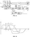
- FIG. 1a is a schematic diagram of implementation of a method for determining a commutation error in a related art.
- current and voltage signals of an electric motor are collected through a sensor, then a commutation error compensation signal is obtained from a phase difference between a flux signal ⁇ obtained by a flux observer and a current integral signal fidt obtained by a current integral module.
- a phase difference between a back electromotive force signal and a current signal in the electric motor may be replaced by the phase difference between the flux signal ⁇ and the current integral signal fidt.
- FIG. 1b is a schematic diagram of a relationship between a back electromotive force signal e and a current signal i, and a relationship between a flux signal ⁇ and a current integral signal fidt in a method for determining a commutation error in a related art; as shown in FIG.
- the flux signal ⁇ lags the back electromotive force signal e by 90 degrees, while the current integral signal fidt lags the current signal i by 90 degrees; in this way, the phase difference between the back electromotive force signal and the current signal in the electric motor may be replaced by the phase difference between the flux signal ⁇ and the current integral signal fidt ; and the phase difference ⁇ between the flux signal ⁇ and the current integral signal fidt is determined by a phase difference detection module, and then the phase difference is adjusted to 0, to obtain the commutation error compensation signal.
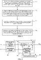
- some embodiments of the invention provide a method for compensating a commutation error of an electric motor, which, as shown in FIG. 2 , includes the following operations.
- a position signal and a three-phase current signal of a rotor that has not been corrected in an electric motor are collected when the rotor rotates in a set direction; here the position signal of the rotor represents a rotation angle of the rotor.
- the electric motor is a BLDC; the set direction may be a clockwise direction or a counterclockwise direction.
- the commutation of the BLDC refers to commutation of the rotor in the BLDC.
- the position signal of the rotor refers to the rotation angle of the rotor, for example, when the rotor rotates 60 degrees, the position signal of the rotor is 60 degrees.
- the position signal of the rotor in the BLDC is from 0 degrees to 360 degrees, and every 60 degrees is classified as a sector, and there are six sectors in total.
- Sector I is from 30 degrees to 90 degrees
- sector II is from 90 degrees to 150 degrees
- sector III is from 150 degrees to 210 degrees
- sector IV is from 210 degrees to 270 degrees
- sector V is from 270 degrees to 330 degrees
- sector VI is from 330 degrees to 30 degrees.
- a rotation of the rotor in the BLDC from the sector I to the sector II or from the sector III to the sector IV means that commutation occurs once.
- the position signal of the rotor in the BLDC in the operation 101 may be obtained by a sensorless technique, or may be directly read by a rotor position sensor (Hall sensor, photoelectric encoder, etc.) in the BLDC.
- the sensorless technique that obtains the position signal of the rotor in the BLDC does not need to be additionally equipped with a sensor and thus reduces hardware cost.
- the scheme for collecting the position signal of the rotor realized by using the rotor position sensor is simple to implement and easy to operate. Embodiments of the invention do not limit the scheme for collecting the position signal of the rotor, and a corresponding scheme may be selected according to actual needs.
- the three-phase current signal in the operation 101 may be obtained by a sampling resistor; the sampling resistor may realize sampling for current and voltage; sampling for current may be realized by connecting a resistor with a small resistance in series, while sampling for voltage may be realized by connecting to a resistor with a big resistance in parallel. In this way, the collection of a three-phase current and a three-phase voltage may be achieved by setting corresponding resistors.
- filtering processing is carried out on the three-phase current signal to obtain a fundamental component of the three-phase current signal, and a position error compensation signal of the electric motor is determined based on the fundamental component of the three-phase current signal.
- the three-phase current signal is not a sine wave but a square wave containing a large number of harmonics. Based on this, it is necessary to filter out the harmonics in the three-phase current signal.
- a neural network filter is constructed to filter the harmonics in the three-phase current signal, and the fundamental component corresponding to the three-phase current signal is obtained without signal offset.
- the operation of carrying out filtering processing on the three-phase current signal to obtain the fundamental component of the three-phase current signal includes the following operations.
- a cosine reference signal and a sine reference signal are determined according to the angular velocity.
- An initial current output signal is determined based on the cosine reference signal and the sine reference signal.
- a weighting signal is generated based on a difference between the three-phase current signal and the initial current output signal.
- the fundamental component of the three-phase current signal is obtained according to the weighting signal, the cosine reference signal and the sine reference signal.
- filtering processing is carried out on the three-phase current signal through the neural network filter to obtain the fundamental component of the three-phase current signal.
- a fundamental function may be determined by an amplitude, an angular velocity and an initial phase, that is, a 1 cos w i t ) + a 2 sin w i t )
- the formula represents a value of a fundamental signal at point i.
- the fundamental function may be constructed through the cosine reference signal and the sine reference signal, and then the fundamental component corresponding to the three-phase current signal may be obtained through an adaptive weighting coefficient.
- FIG. 3 is a schematic diagram of a principle of a neural network filter provided by some embodiments of the invention.
- the neural network filter includes a reference signal input module 501, a filtering output module 502 and a weighting generation module 503.
- the reference signal input module 501 includes a first reference signal input submodule 5011 and a second reference signal input submodule 5012;
- the filtering output module 502 includes a first reference signal processing submodule 5021 and a second reference signal processing submodule 5022.
- Both input signals of the first reference signal input submodule 5011 and the second reference signal input submodule 5012 are related to rotation speed of the BLDC;
- w e is an angular velocity of rotation of the electric motor
- T s is a sampling step size
- n is the number of sampling, r 1 is the cosine reference signal, r 2 is the sine reference signal.
- the weighting signals w 1 and w 2 are generated by the weighting generation module 503; the weighting generation module 503 adaptively generates the weighting signals w 1 and w 2 according to a difference e between the input signal I abc and the output signal y from the filtering output module 502.
- ⁇ is an adaptive learning factor of the neural network filter
- w n-1 is the weighting signal when the number of sampling is n -1
- w n is the weighting signal when the number of sampling is n
- e n is a difference between the input signal I abc and the output signal y from the filtering output module 502 when the number of sampling is n
- an A-phase current I a is subjected to filtering processing by the neural network filter to obtain a corresponding fundamental current signal I a _ l ;
- a B-phase current I b is subjected to filtering processing by the neural network filter to obtain a corresponding fundamental current signal I b _ l ;
- a C-phase current I b is subjected to filtering processing by the neural network filter to obtain a corresponding fundamental current signal I c_l .
- the fundamental components I a_l , I b_l and I c_l of the three-phase current signal are obtained, the fundamental components I a_l , I b_l and I c_l of the three-phase current signal of the BLDC are subjected to vector decomposition to become an excitation current component I d (a d-axis current component I d ) and a torque current component I q (a q-axis current component I q );
- the excitation current I d mainly generates excitation, which controls intensity of a magnetic field in the BLDC, and the q-axis current I q is used to control torque of the BLDC; then when the excitation current I d is 0, all the currents of the BLDC are used to generate electromagnetic torque since the BLDC does not have armature response of the d-axis, that is, the d-axis does not contribute the torque; therefore, in an ideal state, the d-axis current I
- the d-axis current I d is not 0 in practical operation, and then when the d-axis current is adjusted to 0, the position error compensation signal may be determined.
- ⁇ adv is used to denote the position error compensation signal.
- the operation of determining, based on the fundamental component of the three-phase current signal, the position error compensation signal of the electric motor in the operation 102 includes the following operations.
- the fundamental component of the three-phase current signal on a stationary coordinate system is converted into a two-phase current signal on a rotational coordinate system; here a rotation angle of the rotational coordinate system is the same as the rotation angle of the rotor of the electric motor, the two-phase current signal includes a d-axis current corresponding to one axis in the rotational coordinate system.
- the d-axis current is adjusted according to a corresponding relationship between the d-axis current and the position signal of the rotor, to determine the position error compensation signal of the rotor.
- conversion of the fundamental component of the three-phase current signal on the stationary coordinate system into the two-phase current signal on the rotational coordinate system may be implemented by performing Clark conversion and then performing Park conversion.
- the Clark conversion is used to convert the three-phase current signal on the stationary coordinate system into the two-phase current signal on the stationary coordinate system, that is, a three-phase stator coordinate system (three axes are arranged by spacing apart 120 degrees, I a , I b , I c ) is converted into a two-phase stator rectangular coordinate system (two axes are arranged by spacing apart 90 degrees, I ⁇ , I ⁇ ).
- the Park conversion is used to convert the two-phase current signal on the stationary coordinate system into the two-phase current signal on the rotational coordinate system, that is, the two-phase stator rectangular coordinate system (two axes are arranged by spacing apart 90 degrees, I ⁇ , I ⁇ ) is converted into a two-phase rotor rectangular coordinate system (two axes are arranged by spacing apart 90 degrees, I d , I q ).
- the two-phase current signal on the rotational coordinate system includes the d-axis current corresponding to one axis in the rotational coordinate system, and a q-axis current corresponding to the other axis in the rotational coordinate system.
- I d is current of the d-axis
- I q is current of the q-axis.
- FIG. 4 is a schematic diagram of projecting a voltage vector on a stationary two-axis coordinate system ⁇ , ⁇ onto a d-axis and a q-axis of a rotational two-axis coordinate system.
- OF is a synthesized current vector for I d
- I q . j is an angle between the d-axis and the ⁇ -axis, which refers to the rotation angle of the voltage vector on the stationary two-axis coordinate system ⁇ , ⁇ projected to the d-axis and q-axis of the rotating two-axis coordinate system.
- the corresponding relationship between the d-axis current and the position signal of the rotor may be adjusted by a regulator to determine the position error compensation signal of the rotor.
- the regulator may be a proportional regulator, and a difference between the actual value I d and the given value 0 is input to the proportional regulator through a set proportionality coefficient, and a corresponding error compensation signal is output.
- the proportionality coefficient is the ratio of angle to current. In this way, the position error compensation signal ⁇ adv may be obtained.
- an ideal phase interval of the rotor is determined according to the position error compensation signal and the position signal of the rotor.
- the ideal phase interval refers to an ideal corresponding sector.
- the position signal of the rotor is an actual position signal of the rotor collected in the operation 101, or a position signal that has not been corrected, and is represented by ⁇ .
- sector I is from 30 degrees to 90 degrees
- sector II is from 90 degrees to 150 degrees
- sector III is from 150 degrees to 210 degrees
- sector IV is from 210 degrees to 270 degrees
- sector V is from 270 degrees to 330 degrees
- sector VI is from 330 degrees to 30 degrees.
- the ideal position signal ⁇ 0 of the rotor may be obtained, and the ideal position signal ⁇ 0 of the rotor has a corresponding relationship with a sector; in this way, an ideal corresponding sector of the rotor may be determined; for example, assuming that the position signal of the rotor is 120 degrees, then it corresponds to sector II.
- the operation of determining, according to the position error compensation signal ⁇ adv and the position signal ⁇ of the rotor, the ideal phase interval of the rotor includes the following operations.
- the position error compensation signal ⁇ adv is compensated to the position signal ⁇ of the rotor that has not been corrected, to obtain an ideal position signal ⁇ 0 of the rotor.
- the ideal phase interval of the rotor is determined according to a corresponding relationship between a preset phase interval and the position signal of the rotor.
- the ideal position signal ⁇ 0 may be determined by adding the position error compensation signal ⁇ adv and the position signal ⁇ of the rotor.
- the corresponding relationship between the preset sector and the position signal of the rotor refers to a corresponding relationship between the sector and the position signal of the rotor under an ideal condition.
- a corresponding sector may be obtained by finding in a mapping table preset in a program, or it may be obtained by another manner, which is not limited here.
- FIG. 5 is a schematic diagram of a corresponding relationship between a preset sector and a position signal of a rotor.
- the position of the rotor in the BLDC is from 0 degrees to 360 degrees, every 60 degrees is classified as a sector; and the driver outputs the corresponding drive scheme in each sector.
- A, B, and C represent A-phase, B-phase and C-phase of the BLDC respectively; + and - represent an upper switching device and a lower switching device of each of the phases respectively.
- an adjustment scheme for the rotor of the electric motor is determined according to the ideal phase interval of the rotor, and the rotor of the electric motor is commutated according to the adjustment scheme.
- the operation of determining, according to the ideal corresponding sector of the rotor, the adjustment scheme for the rotor of the electric motor includes the following operations.
- a control voltage required for adjusting the rotor is determined.
- the adjustment scheme for the rotor of the electric motor is determined based on the control voltage and the ideal phase interval of the rotor.
- control voltage is used to control each of switching devices in a three-phase full-bridge circuit to determine operating state of each of the switching devices, and implement the commutation of the BLDC at an ideal position by controlling the operating state of each of the switching devices.
- the three-phase full-bridge circuit includes six switching devices S1 to S6.
- six switching devices S1 to S6 in the three-phase full-bridge circuit correspond to different PWM drive signals respectively, that is, three-phase six-state PWM drive signals.
- the PWM drive signal of each of the switching devices may control the operating state of the corresponding switching device. In this way, commutation of the rotor may be implemented by controlling the corresponding switching device through the drive signal.
- the control relationship between the control voltage and each of the switching devices in the three-phase full-bridge circuit may be shown in FIG. 6 , there are three states of each of the switching devices in FIG. 6 : a PWM state, an all-on state and an off state; here the three states directly reflect the operating voltage acting on each of the switching devices.
- a PWM state a PWM state
- an all-on state a PWM state
- an off state a state of each of the switching devices in FIG. 6
- the three states directly reflect the operating voltage acting on each of the switching devices.
- the drive scheme A+B- corresponding to the position of 40 degrees where the rotor in the BLDC is located is found from FIG. 5 ; that is, the upper switching device S1 of A-phase and the lower switching device S4 of B-phase in FIG. 6 are turned on at this time, and the remaining four devices S2, S3, S5, S6 are turned off, to obtain the operating voltage of each of the switching devices in the three-phase full-bridge circuit.
- a duty cycle of the PWM drive signal may be determined by obtaining the control voltage, since the duty cycle of the PWM drive signal directly reflects the amplitude of the PWM drive signal, it may be used to control a manner in which the switching devices in the three-phase full-bridge circuit operate.
- the adjustment scheme for the rotor of the electric motor is determined based on the duty cycle of the PWM drive signal determined by the control voltage and the ideal corresponding sector of the rotor.
- the operation of determining the control voltage required for adjusting the rotor includes the following operations.
- a current angular velocity and a given angular velocity of the rotor that has not been corrected in the electric motor are obtained; here the given angular velocity is a desired angular velocity.
- the control voltage required for adjusting the rotor is determined by using a regulator to process a difference between the current angular velocity and the given angular velocity.
- the angular velocity ⁇ of the rotor may be obtained by differentiating the position signal ⁇ .
- the current angular velocity ⁇ may be obtained by differentiating the collected current position signal ⁇ ; the given angular velocity is the desired angular velocity.
- the current angular velocity ⁇ refers to the actual angular velocity obtained by differentiating the collected position signal ⁇ .
- the regulator that processes the difference between the current angular velocity and the given angular velocity may be a rotation speed regulator; the rotation speed regulator is a regulator for adjusting rotation speed.
- the control voltage is obtained by making the difference between the collected angular velocity and the given angular velocity used as an input value and input into the rotation speed regulator.
- the duty cycle of PWM may be controlled according to the control voltage to generate the corresponding control signal, and the operating states of the switching devices in the three-phase full bridge are controlled by the control signal to drive the BLDC.
- the BLDC has six sectors, and it is implemented by using a hardware system as shown in FIG. 7 .
- the hardware system includes: a BLDC 701, a three-phase terminal current sampling resistor 702, a three-phase full-bridge 703, a battery 704, a capacitor 705, a Micro Controller Unit (MCU) 706, and a position sensor 707; S1 to S6 are control switches.
- the MCU 706 controls the three-phase full-bridge 703 through the drive signal to control the BLDC 701; the MCU 706 collects the position signal through the position sensor 707; the MCU 706 collects the current signal through the three-phase terminal current sampling resistor 702.
- Three phases of the BLDC 701 are connected to three sets of current sampling resistors respectively, namely the three-phase terminal current sampling resistor 702.
- FIG. 8 is a schematic diagram of a corresponding relationship among a BLDC line back electromotive force waveform, a sector and a drive signal;
- waveforms 401, 402 and 403 are back electromotive force waveforms of lines AB, BC and CA of the BLDC respectively, the phase difference between any two of the back electromotive force phases of the three lines is 120 degrees, an electromagnetic period of a BLDC body includes 6 sectors, their numbers are sector I, sector II, sector III, sector IV , sector V and sector VI respectively, boundary of a sector is an angular position of commutation of the BLDC, and in an ideal state, the angular interval between any two of the sectors is 60 degrees.
- the position error compensation signal ⁇ adv is obtained through the provided method for compensating a commutation error
- the ideal position signal ⁇ 0 is obtained by adding the position compensation signal ⁇ adv to the collected position signal ⁇ , thereby implementing commutation of the BLDC.
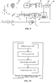
- FIG. 9 is a schematic diagram of implementation of a method for compensating a commutation error of an electric motor provided by some embodiments of the invention.
- the three-phase current signal of the BLDC 205 is collected through the sampling resistor 207 to obtain I abc ( I a , I b , I c ); filtering processing is carried out on the three-phase current signal I abc through the neural network filter 208 to obtain corresponding fundamental components I a_l , I b_l and I c_l , the fundamental components I a_l , I b_l and I c_l of the three-phase current signal of the BLDC are subjected to vector decomposition through coordinate conversion 209 to become an excitation current component I d (a d-axis current component I d ); considering that the d-axis current I d of the electric motor is 0 in an ideal state, the position error compensation signal ⁇ adv is obtained by adjusting I d to 0 by
- the position signal ⁇ of the BLDC is collected by a sensor 206 and a position detection unit 211, and the position signal ⁇ is processed by a differentiation module 212 to obtain a current angular velocity ⁇ .
- a difference between the current angular velocity ⁇ and the given angular velocity ⁇ ⁇ is input to the rotation speed regulator 201 for adjustment, and accordingly, the control voltage is obtained.
- a logic table 202 for commutation is determined by the control voltage and the ideal position signal ⁇ 0 , and the logic table for commutation refers to a corresponding relationship among the drive signal for commutation, the phase and the sector; finally, the PWM module 203 controls operating states of the switches in the three-phase full-bridge circuit 204 to drive the commutation of the BLDC.
- filtering processing is carried out on the collected three-phase current signal to extract a fundamental component corresponding to each phase current signal of the three-phase current signal; a position error compensation signal of the electric motor is determined based on the obtained fundamental component; and since a fundamental amplitude of the current signal is extracted through the neural network filter, influence brought by signal offset may be greatly reduced.
- an ideal commutation phase of the rotor is determined in combination with the position error compensation signal and the actually collected position signal, so as to implement commutation of the rotor of the electric motor in a corresponding adjustment scheme. In this way, commutation of the BLDC at the ideal commutation point is achieved without introducing the signal offset, and drive performance of the BLDC is ensured.
- the solutions of the embodiments of the invention do not require improvements in hardware, and implement timely commutation for the BLDCM by software only, which does not increase the hardware cost, and is simple and convenient to implement.
- FIG. 10 is schematic structural diagram of composition of an apparatus for compensating a commutation error of an electric motor provided by some embodiments of the invention.
- the apparatus 1000 for compensating a commutation error of an electric motor includes a collection unit 1001, a filtering unit 1002, a determination unit 1003 and a commutation unit 1004.
- the collection unit 1001 is configured to collect a position signal and a three-phase current signal of a rotor that has not been corrected in an electric motor, when the rotor rotates in a set direction; here the position signal of the rotor represents a rotation angle of the rotor.
- the filtering unit 1002 is configured to carry out filtering processing on the three-phase current signal to obtain a fundamental component of the three-phase current signal, and determine, based on the fundamental component of the three-phase current signal, a position error compensation signal of the electric motor.
- the determination unit 1003 is configured to determine, according to the position error compensation signal and the position signal of the rotor, an ideal phase interval of the rotor.
- the commutation unit 1004 is configured to determine, according to the ideal phase interval of the rotor, an adjustment scheme for the rotor of the electric motor, and commutate, according to the adjustment scheme, the rotor of the electric motor.
- the collection unit 1001, the filtering unit 1002, the determination unit 1003 and the commutation unit 1004 may be implemented by a processor in the apparatus for compensating a commutation error of the BLDC.
- the apparatus for compensating a commutation error of the BLDC only uses the division of the above-mentioned program modules as an illustrative example. In a practical application, the above process allocation may be completed by different program modules as needed, that is, the internal structure of the apparatus is divided into different program modules to complete all or part of the above-mentioned processes. Moreover, the embodiments of the apparatus for compensating a commutation error of an electric motor and of the method for compensating a commutation error of an electric motor provided in the above embodiments belong to the same concept, and the specific implementation thereof may refer to the method embodiments for the details, which will not be repeated here.
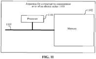
- some embodiments of the invention further provide an apparatus for compensating a commutation error of an electric motor.
- the apparatus 1100 includes a processor 1101, and a memory 1102 configured to store computer programs executable on the processor.
- the processor 1101 is configured to execute the method provided by one or more of the above-mentioned technical solutions when executing the computer programs.
- bus system 1103. the components of the apparatus 1100 are coupled together by a bus system 1103. It may be appreciated that the bus system 1103 is configured to implement connection and communication among these components.
- the bus system 1103 includes, in addition to data bus, power bus, control bus, and status signal bus. For clarity, however, various buses are labeled as the bus system 1103 in FIG. 11 .
- some embodiments of the invention further provide a storage medium, which is a computer-readable storage medium, such as a memory including computer programs executable by the processor of the apparatus for compensating a commutation error of an electric motor, to perform operations described in the foregoing methods.
- the computer-readable storage medium may be Ferromagnetic Random Access Memory (FRAM), Read Only Memory (ROM), Programmable Read-Only Memory (PROM), Erasable Programmable Read-Only Memory (EPROM), Electrically Erasable Programmable Read-Only Memory (EEPROM), Flash Memory, magnetic surface memory, optical disk, or memory such as Compact Disc Read-Only Memory (CD-ROM), etc.
- FRAM Ferromagnetic Random Access Memory
- ROM Read Only Memory
- PROM Programmable Read-Only Memory
- EPROM Erasable Programmable Read-Only Memory
- EEPROM Electrically Erasable Programmable Read-Only Memory
- Flash Memory magnetic surface memory, optical disk, or memory such as Compact Disc Read-Only Memory (CD-ROM),
Landscapes
- Engineering & Computer Science (AREA)
- Power Engineering (AREA)
- Control Of Motors That Do Not Use Commutators (AREA)
Abstract
Description
- The invention relates to the technical field of controlling an electric motor, and in particular to a method and apparatus for compensating a commutation error of an electric motor, and a storage medium.
- Currently, a high-speed miniaturized Brushless Direct Current (BLDC) motor is more and more widely used, especially in the field of small electric tools such as hand-held vacuum cleaners, or the like. Due to existence of factors such as reactance of winding, a conventional drive scheme of the BLDC has commutation errors, which cannot ensure commutation of the high-speed BLDC at an optimal commutation point, so that a phase current lags a corresponding back electromotive force, which brings many adverse effects to performance of the motor.
- In a related art, phase error of the commutation is usually determined by a flux observer and a current integrator, and an error compensation signal is generated. However, such commutation error compensation scheme is based on the premise that resistance and inductance information of the flux observer of an electric motor is accurate, and the current integrator does not have an offset error. However, in practice, the commutation error cannot be accurately detected due to deviation occurred in a manufacturing process and a current signal offset, which makes the high-speed BLDC impossible to commutate at the optimal commutation point, affecting drive performance of the BLDC.
- In order to solve the problem in the related art, embodiments of the invention propose a method and apparatus for compensating a commutation error of an electric motor and a storage medium, which is capable of generating an ideal commutation error compensation signal to ensure commutation of the BLDC at the optimal commutation point.
- Embodiments of the invention provide a method for compensating a commutation error of an electric motor, which includes the following operations.
- A position signal and a three-phase current signal of a rotor that has not been corrected in an electric motor are collected when the rotor rotates in a set direction; here the position signal of the rotor represents a rotation angle of the rotor.
- Filtering processing is carried out on the three-phase current signal to obtain a fundamental component of the three-phase current signal, and a position error compensation signal of the electric motor is determined based on the fundamental component of the three-phase current signal.
- An ideal phase interval of the rotor is determined according to the position error compensation signal and the position signal of the rotor.
- An adjustment scheme for the rotor of the electric motor is determined according to the ideal phase interval of the rotor, and the rotor of the electric motor is commutated according to the adjustment scheme.
- In the above solution, the operation of carrying out filtering processing on the three-phase current signal to obtain the fundamental component of the three-phase current signal includes the following operations.
- An angular velocity of the rotor that has not been corrected in the electric motor is obtained.
- A cosine reference signal and a sine reference signal are determined according to the angular velocity.
- An initial current output signal is determined based on the cosine reference signal and the sine reference signal.
- A weighting signal is generated based on a difference between the three-phase current signal and the initial current output signal.
- The fundamental component of the three-phase current signal is obtained according to the weighting signal, the cosine reference signal and the sine reference signal.
- In the above solution, the operation of determining, based on the fundamental component of the three-phase current signal, the position error compensation signal of the electric motor includes the following operations.
- The fundamental component of the three-phase current signal on a stationary coordinate system is converted into a two-phase current signal on a rotational coordinate system; here a rotation angle of the rotational coordinate system is the same as the rotation angle of the rotor of the electric motor, the two-phase current signal includes a d-axis current corresponding to one axis in the rotational coordinate system.
- The d-axis current is adjusted according to a corresponding relationship between the d-axis current and the position signal of the rotor, to determine the position error compensation signal of the rotor.
- In the above solution, the operation of determining, according to the position error compensation signal and the position signal of the rotor, the ideal phase interval of the rotor includes the following operations.
- The position error compensation signal is compensated to the position signal of the rotor that has not been corrected, to obtain an ideal position signal of the rotor.
- The ideal phase interval of the rotor is determined according to a corresponding relationship between a preset phase interval and the position signal of the rotor.
- In the above solution, the operation of determining, according to the ideal phase interval of the rotor, the adjustment scheme for the rotor of the electric motor includes the following operations.
- A control voltage required for adjusting the rotor is determined.
- The adjustment scheme for the rotor of the electric motor is determined based on the control voltage and the ideal phase interval of the rotor.
- In the above solution, the operation of determining the control voltage required for adjusting the rotor includes the following operations.
- A current angular velocity and a given angular velocity of the rotor that has not been corrected in the electric motor are obtained; here the given angular velocity is a desired angular velocity.
- The control voltage required for adjusting the rotor is determined by using a regulator to process a difference between the current angular velocity and the given angular velocity.
- Embodiments of the invention further provide an apparatus for compensating a commutation error of an electric motor, which includes a collection unit, a filtering unit, a determination unit and a commutation unit.
- The collection unit is configured to collect a position signal and a three-phase current signal of a rotor that has not been corrected in an electric motor, when the rotor rotates in a set direction; here the position signal of the rotor represents a rotation angle of the rotor.
- The filtering unit is configured to carry out filtering processing on the three-phase current signal to obtain a fundamental component of the three-phase current signal, and determine, based on the fundamental component of the three-phase current signal, a position error compensation signal of the electric motor.
- The determination unit is configured to determine, according to the position error compensation signal and the position signal of the rotor, an ideal phase interval of the rotor.
- The commutation unit is configured to determine, according to the ideal phase interval of the rotor, an adjustment scheme for the rotor of the electric motor, and commutate, according to the adjustment scheme, the rotor of the electric motor.
- Embodiments of the invention further provide an apparatus for compensating a commutation error of an electric motor, which includes a processor, and a memory configured to store computer programs executable on the processor.
- The processor is configured to perform operations of any one of the above methods when executing the computer programs.
- Embodiments of the invention further provide a storage medium having stored therein computer programs that, when executed by a processor, causes the processor to implement operations of any one of the above methods.
- According to the method and apparatus for compensating a commutation error of the electric motor, and the storage medium provided by the embodiments of the invention, filtering processing is carried out on the collected three-phase current signal to extract a fundamental component corresponding to each phase current signal of the three-phase current signal; a position error compensation signal of the electric motor is determined based on the obtained fundamental component; and since a harmonic in the current signal are removed by filtering processing, signal offset does not occur in the obtained fundamental component. Based on this, an ideal commutation phase of the rotor is determined in combination with the position error compensation signal and the actually collected position signal, so as to implement commutation of the rotor of the electric motor in a corresponding adjustment scheme. In this way, commutation of the BLDC at the optimal commutation point is achieved without introducing the signal offset, and drive performance of the BLDC is ensured.
-
-
FIG. 1a is a schematic diagram of implementation of a method for determining a commutation error in a related art. -
FIG. 1b is a schematic diagram of a relationship between a back electromotive force signal e and a current signal i, and a relationship between a flux signal ψ and a current integral signal fidt in a method for determining a commutation error in a related art. -
FIG. 2 is a method for compensating a commutation error of an electric motor provided by some embodiments of the invention. -
FIG. 3 is a schematic diagram of a principle of a neural network filter provided by some embodiments of the invention. -
FIG. 4 is a schematic diagram of projecting a voltage vector on a stationary two-axis coordinate system α, β onto a d-axis and a q-axis of a rotational two-axis coordinate system. -
FIG. 5 is a schematic diagram of a corresponding relationship among a preset sector, a position signal and a drive scheme of a rotor. -
FIG. 6 is a schematic diagram of a control relationship between a control voltage and switching devices in a three-phase full-bridge circuit. -
FIG. 7 is a schematic structural diagram of a hardware system of a BLDC applied into an electronic device of some embodiments of the invention. -
FIG. 8 is a schematic diagram of a corresponding relationship among a BLDC line back electromotive force waveform, a sector and a drive signal. -
FIG. 9 is a schematic diagram of implementation of a method for compensating a commutation error of an electric motor provided by some embodiments of the invention. -
FIG. 10 is a schematic structural diagram of composition of an apparatus for compensating a commutation error of an electric motor provided by some embodiments of the invention. -
FIG. 11 is a schematic structural diagram of hardware composition of an apparatus for compensating a commutation error of an electric motor provided by some embodiments of the invention. - In order to make the objective, technical solutions and advantages of embodiments of the invention clearer, specific technical solutions of the invention are further described in detail below in conjunction with the accompanying drawings of the embodiments of the invention. The following embodiments are intended to explain the invention, but are not intended to limit the scope of the invention.
- A method for determining a commutation error is proposed in a related art.
FIG. 1a is a schematic diagram of implementation of a method for determining a commutation error in a related art. As shown inFIG. 1a , current and voltage signals of an electric motor are collected through a sensor, then a commutation error compensation signal is obtained from a phase difference between a flux signal ψ obtained by a flux observer and a current integral signal fidt obtained by a current integral module. Here, in the method of determining the commutation error, it is proposed that a phase difference between a back electromotive force signal and a current signal in the electric motor may be replaced by the phase difference between the flux signal ψ and the current integral signal fidt. -
FIG. 1b is a schematic diagram of a relationship between a back electromotive force signal e and a current signal i, and a relationship between a flux signal ψ and a current integral signal fidt in a method for determining a commutation error in a related art; as shown inFIG. 1b , the flux signal ψ lags the back electromotive force signal e by 90 degrees, while the current integral signal fidt lags the current signal i by 90 degrees; in this way, the phase difference between the back electromotive force signal and the current signal in the electric motor may be replaced by the phase difference between the flux signal ψ and the current integral signal fidt; and the phase difference α between the flux signal ψ and the current integral signal fidt is determined by a phase difference detection module, and then the phase difference is adjusted to 0, to obtain the commutation error compensation signal. - However, such commutation error compensation scheme is based on the premise that resistance and inductance information of the flux observer of an electric motor is accurate, and the current integrator does not have an offset error. However, in practice, resistance and inductance parameters of the high-speed electric motor are relatively small, it is easy to cause actual resistance and inductance parameters to be different from their corresponding theoretical values in practical manufacturing process due to modular manufacturing, asymmetry in the number of turns, different line contacting resistances, therefore the resistance and inductance of the flux observer model are inaccurate. In addition, the current signal will generate a direct current offset component after it is processed by a integral module, the offset will introduce an error in a zero-crossing point of the current integral signal, affecting detection of the phase difference.
- Based on this, in order to compensate the commutation error, some embodiments of the invention provide a method for compensating a commutation error of an electric motor, which, as shown in
FIG. 2 , includes the following operations. - In
operation 101, a position signal and a three-phase current signal of a rotor that has not been corrected in an electric motor are collected when the rotor rotates in a set direction; here the position signal of the rotor represents a rotation angle of the rotor. - In some embodiments of the invention, the electric motor is a BLDC; the set direction may be a clockwise direction or a counterclockwise direction. The commutation of the BLDC refers to commutation of the rotor in the BLDC. The position signal of the rotor refers to the rotation angle of the rotor, for example, when the rotor rotates 60 degrees, the position signal of the rotor is 60 degrees.
- In a practical application, the position signal of the rotor in the BLDC is from 0 degrees to 360 degrees, and every 60 degrees is classified as a sector, and there are six sectors in total. Sector I is from 30 degrees to 90 degrees, sector II is from 90 degrees to 150 degrees, sector III is from 150 degrees to 210 degrees, sector IV is from 210 degrees to 270 degrees, sector V is from 270 degrees to 330 degrees, and sector VI is from 330 degrees to 30 degrees. A rotation of the rotor in the BLDC from the sector I to the sector II or from the sector III to the sector IV means that commutation occurs once.
- In a practical application, the position signal of the rotor in the BLDC in the
operation 101 may be obtained by a sensorless technique, or may be directly read by a rotor position sensor (Hall sensor, photoelectric encoder, etc.) in the BLDC. - It should be noted that compared with the manner of reading the rotor position sensor, the sensorless technique that obtains the position signal of the rotor in the BLDC does not need to be additionally equipped with a sensor and thus reduces hardware cost. However, the scheme for collecting the position signal of the rotor realized by using the rotor position sensor is simple to implement and easy to operate. Embodiments of the invention do not limit the scheme for collecting the position signal of the rotor, and a corresponding scheme may be selected according to actual needs.
- The three-phase current signal in the
operation 101 may be obtained by a sampling resistor; the sampling resistor may realize sampling for current and voltage; sampling for current may be realized by connecting a resistor with a small resistance in series, while sampling for voltage may be realized by connecting to a resistor with a big resistance in parallel. In this way, the collection of a three-phase current and a three-phase voltage may be achieved by setting corresponding resistors. - In
operation 102, filtering processing is carried out on the three-phase current signal to obtain a fundamental component of the three-phase current signal, and a position error compensation signal of the electric motor is determined based on the fundamental component of the three-phase current signal. - For the drive scheme of the BLDC, the three-phase current signal is not a sine wave but a square wave containing a large number of harmonics. Based on this, it is necessary to filter out the harmonics in the three-phase current signal. In some embodiments of the invention, a neural network filter is constructed to filter the harmonics in the three-phase current signal, and the fundamental component corresponding to the three-phase current signal is obtained without signal offset.
- Here the operation of carrying out filtering processing on the three-phase current signal to obtain the fundamental component of the three-phase current signal includes the following operations.
- An angular velocity of the rotor that has not been corrected in the electric motor is obtained.
- A cosine reference signal and a sine reference signal are determined according to the angular velocity.
- An initial current output signal is determined based on the cosine reference signal and the sine reference signal.
- A weighting signal is generated based on a difference between the three-phase current signal and the initial current output signal.
- The fundamental component of the three-phase current signal is obtained according to the weighting signal, the cosine reference signal and the sine reference signal.
- It should be noted that in some embodiments of the invention, filtering processing is carried out on the three-phase current signal through the neural network filter to obtain the fundamental component of the three-phase current signal. Since a fundamental function may be determined by an amplitude, an angular velocity and an initial phase, that is, a1 cos wit) + a2 sin wit ), the formula represents a value of a fundamental signal at point i. In this way, the fundamental function may be constructed through the cosine reference signal and the sine reference signal, and then the fundamental component corresponding to the three-phase current signal may be obtained through an adaptive weighting coefficient.
- Here the filtering processing of the three-phase current signal will be illustrated with reference to
FIG. 3 . -
FIG. 3 is a schematic diagram of a principle of a neural network filter provided by some embodiments of the invention. As shown inFIG. 3 , the neural network filter includes a referencesignal input module 501, afiltering output module 502 and aweighting generation module 503. The referencesignal input module 501 includes a first reference signal input submodule 5011 and a second referencesignal input submodule 5012; thefiltering output module 502 includes a first referencesignal processing submodule 5021 and a second referencesignal processing submodule 5022. - Both input signals of the first reference signal input submodule 5011 and the second reference
signal input submodule 5012 are related to rotation speed of the BLDC; the first referencesignal input submodule 5011 may be expressed as r 1 = cos wenTs ); the second referencesignal input submodule 5012 may be expressed as r 1 = cos wenTs ); we is an angular velocity of rotation of the electric motor, Ts is a sampling step size, n is the number of sampling, r1 is the cosine reference signal, r2 is the sine reference signal. - Input signals of the first reference
signal processing submodule 5021 are the cosine reference signal r1 and a weighting signal w1 ; an output signal thereof is y1 ; here
- Input signals of the second reference
signal processing submodule 5022 are the sine reference signal r2 and a weighting signal w2 ; an output signal thereof is y2 ; here
- The cosine reference signal r1, the sine reference signal r2, and corresponding weighting signals w1 , w2 are used as input signals of the
filtering output module 502 and input into thefiltering output module 502, and an initial current output signal y 0 is output, that is,
- As shown in
FIG. 3 , the weighting signals w1 and w2 are generated by theweighting generation module 503; theweighting generation module 503 adaptively generates the weighting signals w1 and w2 according to a difference e between the input signal Iabc and the output signal y from thefiltering output module 502. The adjustment process may be expressed as:

- Where η is an adaptive learning factor of the neural network filter, wn-1 is the weighting signal when the number of sampling is n-1, wn is the weighting signal when the number of sampling is n, and en is a difference between the input signal Iabc and the output signal y from the
filtering output module 502 when the number of sampling is n, here en may be expressed as:

- In a practical application, when the input signal Iabc is subjected to filtering processing by the neural network filter, the filtering processing is carried out separately, and currents of the three phases do not affect each other, that is, an A-phase current Ia is subjected to filtering processing by the neural network filter to obtain a corresponding fundamental current signal I a_l ; a B-phase current Ib is subjected to filtering processing by the neural network filter to obtain a corresponding fundamental current signal I b_l ; a C-phase current Ib is subjected to filtering processing by the neural network filter to obtain a corresponding fundamental current signal Ic_l.
- Since a fundamental amplitude of the current signal is extracted through the neural network filter, influence brought by signal offset may be greatly reduced, so that there is no error occurred in a fundamental phase of the extracted current signal, which provide a foundation for accurate determination of a subsequent compensation signal.
- In some embodiments of the invention, after the fundamental components Ia_l , Ib_l and Ic_l of the three-phase current signal are obtained, the fundamental components Ia_l , Ib_l and Ic_l of the three-phase current signal of the BLDC are subjected to vector decomposition to become an excitation current component Id (a d-axis current component Id ) and a torque current component Iq (a q-axis current component Iq ); the excitation current Id mainly generates excitation, which controls intensity of a magnetic field in the BLDC, and the q-axis current Iq is used to control torque of the BLDC; then when the excitation current Id is 0, all the currents of the BLDC are used to generate electromagnetic torque since the BLDC does not have armature response of the d-axis, that is, the d-axis does not contribute the torque; therefore, in an ideal state, the d-axis current Id of the electric motor is 0. In the high-speed BLDC, due to existence of factors such as reactance of winding, the d-axis current Id is not 0 in practical operation, and then when the d-axis current is adjusted to 0, the position error compensation signal may be determined. Here θadv is used to denote the position error compensation signal.
- In this way, the operation of determining, based on the fundamental component of the three-phase current signal, the position error compensation signal of the electric motor in the
operation 102 includes the following operations. - In operation b1, the fundamental component of the three-phase current signal on a stationary coordinate system is converted into a two-phase current signal on a rotational coordinate system; here a rotation angle of the rotational coordinate system is the same as the rotation angle of the rotor of the electric motor, the two-phase current signal includes a d-axis current corresponding to one axis in the rotational coordinate system.
- In operation b2, the d-axis current is adjusted according to a corresponding relationship between the d-axis current and the position signal of the rotor, to determine the position error compensation signal of the rotor.
- Here, in the operation b1, conversion of the fundamental component of the three-phase current signal on the stationary coordinate system into the two-phase current signal on the rotational coordinate system may be implemented by performing Clark conversion and then performing Park conversion. The Clark conversion is used to convert the three-phase current signal on the stationary coordinate system into the two-phase current signal on the stationary coordinate system, that is, a three-phase stator coordinate system (three axes are arranged by spacing apart 120 degrees, Ia, Ib, Ic ) is converted into a two-phase stator rectangular coordinate system (two axes are arranged by spacing apart 90 degrees, Iα , Iβ ). The Park conversion is used to convert the two-phase current signal on the stationary coordinate system into the two-phase current signal on the rotational coordinate system, that is, the two-phase stator rectangular coordinate system (two axes are arranged by spacing apart 90 degrees, Iα , Iβ ) is converted into a two-phase rotor rectangular coordinate system (two axes are arranged by spacing apart 90 degrees, Id , Iq ).
- The two-phase current signal on the rotational coordinate system includes the d-axis current corresponding to one axis in the rotational coordinate system, and a q-axis current corresponding to the other axis in the rotational coordinate system.
- It should be noted that projection of current vectors on the stationary three-axis coordinate system a, b, c onto α axis and β axis of a stationary two-axis coordinate system may be carried out by the following formula:

- In the formula, Iα is current of the α axis of the stationary two-axis coordinate system α, β; Iβ is current of the β axis of the stationary two-axis coordinate system α, β; Ia is current of an upper a axis in the stationary three-axis coordinate system a, b, c; Ib is current of an upper b axis in the stationary three-axis coordinate system a, b, c; and Ic is current of an upper c axis in the stationary three-axis coordinate system a, b, c; k is a ratio of the effective number of turns of each phase of the three-phase winding to the effective number of turns of each phase of the two-phase winding, and when the total power before and after conversion is unchanged,

- Projection of a voltage vector on the stationary two-axis coordinate system α, β onto a d-axis and a q-axis of a rotational two-axis coordinate system may be performed by the following formula:

- Here j is an angle between the d-axis and the α-axis, specifically referring to the rotation angle of the rotor, Id is current of the d-axis, and Iq is current of the q-axis. In this way, Id and Iq may be determined by the position signal of the rotor and Iα and Iβ collected in the
operation 101. -
FIG. 4 is a schematic diagram of projecting a voltage vector on a stationary two-axis coordinate system α, β onto a d-axis and a q-axis of a rotational two-axis coordinate system. As shown inFIG. 4 ,OF is a synthesized current vector for Id , Iq. j is an angle between the d-axis and the α-axis, which refers to the rotation angle of the voltage vector on the stationary two-axis coordinate system α, β projected to the d-axis and q-axis of the rotating two-axis coordinate system. - After the excitation current component Id and the torque current component Iq are obtained, the corresponding relationship between the d-axis current and the position signal of the rotor may be adjusted by a regulator to determine the position error compensation signal of the rotor.
- Since Clark conversion and then Park conversion are performed on the three-phase current signal, two current components Id and Iq on the rotational coordinate system are obtained, and in an ideal state, Id = 0, thus Id is adjusted to 0 by the regulator, a corresponding position error compensation signal is output. Here the regulator may be a proportional regulator, and a difference between the actual value Id and the given
value 0 is input to the proportional regulator through a set proportionality coefficient, and a corresponding error compensation signal is output. The proportionality coefficient is the ratio of angle to current. In this way, the position error compensation signal θadv may be obtained. - In
operation 103, an ideal phase interval of the rotor is determined according to the position error compensation signal and the position signal of the rotor. - Here the ideal phase interval refers to an ideal corresponding sector. The position signal of the rotor is an actual position signal of the rotor collected in the
operation 101, or a position signal that has not been corrected, and is represented by θ. - As mentioned above, the angle corresponding to one revolution by which the rotor of the BLDC rotates is divided into 6 sectors. Sector I is from 30 degrees to 90 degrees, sector II is from 90 degrees to 150 degrees, sector III is from 150 degrees to 210 degrees, sector IV is from 210 degrees to 270 degrees, sector V is from 270 degrees to 330 degrees, and sector VI is from 330 degrees to 30 degrees. Thus, after the position signal θ of the rotor is compensated, the ideal position signal θ0 of the rotor may be obtained, and the ideal position signal θ0 of the rotor has a corresponding relationship with a sector; in this way, an ideal corresponding sector of the rotor may be determined; for example, assuming that the position signal of the rotor is 120 degrees, then it corresponds to sector II.
- Here the operation of determining, according to the position error compensation signal θadv and the position signal θ of the rotor, the ideal phase interval of the rotor includes the following operations. The position error compensation signal θadv is compensated to the position signal θ of the rotor that has not been corrected, to obtain an ideal position signal θ0 of the rotor. The ideal phase interval of the rotor is determined according to a corresponding relationship between a preset phase interval and the position signal of the rotor.
- It should be noted that after the position error compensation signal θadv is obtained, the ideal position signal θ0 may be determined by adding the position error compensation signal θadv and the position signal θ of the rotor.
- The corresponding relationship between the preset sector and the position signal of the rotor refers to a corresponding relationship between the sector and the position signal of the rotor under an ideal condition. In a practical application, after the position signal of the rotor is determined, a corresponding sector may be obtained by finding in a mapping table preset in a program, or it may be obtained by another manner, which is not limited here.
-
FIG. 5 is a schematic diagram of a corresponding relationship between a preset sector and a position signal of a rotor. As shown inFIG. 5 , in some application embodiments of the invention, the position of the rotor in the BLDC is from 0 degrees to 360 degrees, every 60 degrees is classified as a sector; and the driver outputs the corresponding drive scheme in each sector. In the drive scheme shown inFIG. 5 , A, B, and C represent A-phase, B-phase and C-phase of the BLDC respectively; + and - represent an upper switching device and a lower switching device of each of the phases respectively. - In
operation 104, an adjustment scheme for the rotor of the electric motor is determined according to the ideal phase interval of the rotor, and the rotor of the electric motor is commutated according to the adjustment scheme. - It should be noted that the operation of determining, according to the ideal corresponding sector of the rotor, the adjustment scheme for the rotor of the electric motor includes the following operations. A control voltage required for adjusting the rotor is determined. The adjustment scheme for the rotor of the electric motor is determined based on the control voltage and the ideal phase interval of the rotor.
- Here the control voltage is used to control each of switching devices in a three-phase full-bridge circuit to determine operating state of each of the switching devices, and implement the commutation of the BLDC at an ideal position by controlling the operating state of each of the switching devices. The three-phase full-bridge circuit includes six switching devices S1 to S6. In a practical application, six switching devices S1 to S6 in the three-phase full-bridge circuit correspond to different PWM drive signals respectively, that is, three-phase six-state PWM drive signals. The PWM drive signal of each of the switching devices may control the operating state of the corresponding switching device. In this way, commutation of the rotor may be implemented by controlling the corresponding switching device through the drive signal.
- The control relationship between the control voltage and each of the switching devices in the three-phase full-bridge circuit may be shown in
FIG. 6 , there are three states of each of the switching devices inFIG. 6 : a PWM state, an all-on state and an off state; here the three states directly reflect the operating voltage acting on each of the switching devices. For example, assuming that the rotor in the BLDC is at the position of 40 degrees, and the drive scheme A+B- corresponding to the position of 40 degrees where the rotor in the BLDC is located is found fromFIG. 5 ; that is, the upper switching device S1 of A-phase and the lower switching device S4 of B-phase inFIG. 6 are turned on at this time, and the remaining four devices S2, S3, S5, S6 are turned off, to obtain the operating voltage of each of the switching devices in the three-phase full-bridge circuit. - It should be noted that a duty cycle of the PWM drive signal may be determined by obtaining the control voltage, since the duty cycle of the PWM drive signal directly reflects the amplitude of the PWM drive signal, it may be used to control a manner in which the switching devices in the three-phase full-bridge circuit operate. Thus, the adjustment scheme for the rotor of the electric motor is determined based on the duty cycle of the PWM drive signal determined by the control voltage and the ideal corresponding sector of the rotor.
- It should be noted that the operation of determining the control voltage required for adjusting the rotor includes the following operations.
- A current angular velocity and a given angular velocity of the rotor that has not been corrected in the electric motor are obtained; here the given angular velocity is a desired angular velocity.
- The control voltage required for adjusting the rotor is determined by using a regulator to process a difference between the current angular velocity and the given angular velocity.
- Here, since a relationship between the angular velocity and the position signal of the rotor is θ = ωt, the angular velocity ω of the rotor may be obtained by differentiating the position signal θ. In this way, the current angular velocity ω may be obtained by differentiating the collected current position signal θ; the given angular velocity is the desired angular velocity. The current angular velocity ω refers to the actual angular velocity obtained by differentiating the collected position signal θ.
- The regulator that processes the difference between the current angular velocity and the given angular velocity may be a rotation speed regulator; the rotation speed regulator is a regulator for adjusting rotation speed. In a specific implementation, the control voltage is obtained by making the difference between the collected angular velocity and the given angular velocity used as an input value and input into the rotation speed regulator.
- After the control voltage is determined, the duty cycle of PWM may be controlled according to the control voltage to generate the corresponding control signal, and the operating states of the switching devices in the three-phase full bridge are controlled by the control signal to drive the BLDC.
- The invention will be described in detail below in conjunction with specific application examples.
- In some application embodiments, the BLDC has six sectors, and it is implemented by using a hardware system as shown in
FIG. 7 . As shown inFIG. 7 , the hardware system includes: aBLDC 701, a three-phase terminalcurrent sampling resistor 702, a three-phase full-bridge 703, abattery 704, acapacitor 705, a Micro Controller Unit (MCU) 706, and aposition sensor 707; S1 to S6 are control switches. TheMCU 706 controls the three-phase full-bridge 703 through the drive signal to control theBLDC 701; theMCU 706 collects the position signal through theposition sensor 707; theMCU 706 collects the current signal through the three-phase terminalcurrent sampling resistor 702. Three phases of theBLDC 701 are connected to three sets of current sampling resistors respectively, namely the three-phase terminalcurrent sampling resistor 702. -
FIG. 8 is a schematic diagram of a corresponding relationship among a BLDC line back electromotive force waveform, a sector and a drive signal; inFIG. 8 ,waveforms - In some embodiments of the invention, the position error compensation signal θadv is obtained through the provided method for compensating a commutation error, and the ideal position signal θ0 is obtained by adding the position compensation signal θadv to the collected position signal θ, thereby implementing commutation of the BLDC.
-
FIG. 9 is a schematic diagram of implementation of a method for compensating a commutation error of an electric motor provided by some embodiments of the invention; as shown inFIG. 9 , the three-phase current signal of theBLDC 205 is collected through thesampling resistor 207 to obtain Iabc (Ia, Ib, Ic ); filtering processing is carried out on the three-phase current signal Iabc through theneural network filter 208 to obtain corresponding fundamental components Ia_l, Ib_l and Ic_l , the fundamental components Ia_l , Ib_l and Ic_l of the three-phase current signal of the BLDC are subjected to vector decomposition through coordinateconversion 209 to become an excitation current component Id (a d-axis current component Id ); considering that the d-axis current Id of the electric motor is 0 in an ideal state, the position error compensation signal θadv is obtained by adjusting Id to 0 by theregulator 210. The position error compensation signal θadv and the collected position signal θ are added to obtain an ideal position signal θ0 . - On the other hand, the position signal θ of the BLDC is collected by a
sensor 206 and aposition detection unit 211, and the position signal θ is processed by adifferentiation module 212 to obtain a current angular velocity ω. After a given angular velocity ω ∗ is obtained, a difference between the current angular velocity ω and the given angular velocity ω ∗ is input to therotation speed regulator 201 for adjustment, and accordingly, the control voltage is obtained. In this way, a logic table 202 for commutation is determined by the control voltage and the ideal position signal θ0 , and the logic table for commutation refers to a corresponding relationship among the drive signal for commutation, the phase and the sector; finally, thePWM module 203 controls operating states of the switches in the three-phase full-bridge circuit 204 to drive the commutation of the BLDC. - According to the method and apparatus for compensating a commutation error of the electric motor, and the storage medium provided by the embodiments of the invention, filtering processing is carried out on the collected three-phase current signal to extract a fundamental component corresponding to each phase current signal of the three-phase current signal; a position error compensation signal of the electric motor is determined based on the obtained fundamental component; and since a fundamental amplitude of the current signal is extracted through the neural network filter, influence brought by signal offset may be greatly reduced. Based on this, an ideal commutation phase of the rotor is determined in combination with the position error compensation signal and the actually collected position signal, so as to implement commutation of the rotor of the electric motor in a corresponding adjustment scheme. In this way, commutation of the BLDC at the ideal commutation point is achieved without introducing the signal offset, and drive performance of the BLDC is ensured.
- Moreover, the solutions of the embodiments of the invention do not require improvements in hardware, and implement timely commutation for the BLDCM by software only, which does not increase the hardware cost, and is simple and convenient to implement.
- In order to implement the method according to some embodiments of the invention, some embodiments of the invention further provide an apparatus for compensating a commutation error of an electric motor, and
FIG. 10 is schematic structural diagram of composition of an apparatus for compensating a commutation error of an electric motor provided by some embodiments of the invention. As shown inFIG. 10 , the apparatus 1000 for compensating a commutation error of an electric motor includes acollection unit 1001, afiltering unit 1002, adetermination unit 1003 and acommutation unit 1004. - The
collection unit 1001 is configured to collect a position signal and a three-phase current signal of a rotor that has not been corrected in an electric motor, when the rotor rotates in a set direction; here the position signal of the rotor represents a rotation angle of the rotor. - The
filtering unit 1002 is configured to carry out filtering processing on the three-phase current signal to obtain a fundamental component of the three-phase current signal, and determine, based on the fundamental component of the three-phase current signal, a position error compensation signal of the electric motor. - The
determination unit 1003 is configured to determine, according to the position error compensation signal and the position signal of the rotor, an ideal phase interval of the rotor. - The
commutation unit 1004 is configured to determine, according to the ideal phase interval of the rotor, an adjustment scheme for the rotor of the electric motor, and commutate, according to the adjustment scheme, the rotor of the electric motor. - In a practical application, the
collection unit 1001, thefiltering unit 1002, thedetermination unit 1003 and thecommutation unit 1004 may be implemented by a processor in the apparatus for compensating a commutation error of the BLDC. - It should be noted that when performing the control of commutation for the BLDC, the apparatus for compensating a commutation error of the BLDC provided by the above embodiments only uses the division of the above-mentioned program modules as an illustrative example. In a practical application, the above process allocation may be completed by different program modules as needed, that is, the internal structure of the apparatus is divided into different program modules to complete all or part of the above-mentioned processes. Moreover, the embodiments of the apparatus for compensating a commutation error of an electric motor and of the method for compensating a commutation error of an electric motor provided in the above embodiments belong to the same concept, and the specific implementation thereof may refer to the method embodiments for the details, which will not be repeated here.
- Based on the hardware implementation of the above-mentioned program modules, and in order to implement the method according to the embodiments of the invention, some embodiments of the invention further provide an apparatus for compensating a commutation error of an electric motor. As shown in
FIG. 11 , the apparatus 1100 includes aprocessor 1101, and amemory 1102 configured to store computer programs executable on the processor. - The
processor 1101 is configured to execute the method provided by one or more of the above-mentioned technical solutions when executing the computer programs. - In a practical application, as shown in
FIG. 11 , the components of the apparatus 1100 are coupled together by abus system 1103. It may be appreciated that thebus system 1103 is configured to implement connection and communication among these components. Thebus system 1103 includes, in addition to data bus, power bus, control bus, and status signal bus. For clarity, however, various buses are labeled as thebus system 1103 inFIG. 11 . - In exemplary embodiments, some embodiments of the invention further provide a storage medium, which is a computer-readable storage medium, such as a memory including computer programs executable by the processor of the apparatus for compensating a commutation error of an electric motor, to perform operations described in the foregoing methods. The computer-readable storage medium may be Ferromagnetic Random Access Memory (FRAM), Read Only Memory (ROM), Programmable Read-Only Memory (PROM), Erasable Programmable Read-Only Memory (EPROM), Electrically Erasable Programmable Read-Only Memory (EEPROM), Flash Memory, magnetic surface memory, optical disk, or memory such as Compact Disc Read-Only Memory (CD-ROM), etc.
- It should be noted that the terms "first", "second" or the like are used to distinguish among similar objects, rather than describing a specific order or sequence.
- In addition, the technical solutions described in the embodiments of the invention may be combined arbitrarily without conflict.
- The foregoing descriptions are merely illustrative of the preferred embodiments of the invention and are not intended to limit the protection scope of the invention.
Claims (9)
- A method for compensating a commutation error of an electric motor, comprising:collecting a position signal and a three-phase current signal of a rotor that has not been corrected in an electric motor, when the rotor rotates in a set direction; wherein the position signal of the rotor represents a rotation angle of the rotor;carrying out filtering processing on the three-phase current signal to obtain a fundamental component of the three-phase current signal, and determining, based on the fundamental component of the three-phase current signal, a position error compensation signal of the electric motor;determining, according to the position error compensation signal and the position signal of the rotor, an ideal phase interval of the rotor; anddetermining, according to the ideal phase interval of the rotor, an adjustment scheme for the rotor of the electric motor, and commutating, according to the adjustment scheme, the rotor of the electric motor.
- The method of claim 1, wherein carrying out filtering processing on the three-phase current signal to obtain the fundamental component of the three-phase current signal comprises:obtaining an angular velocity of the rotor that has not been corrected in the electric motor;determining, according to the angular velocity, a cosine reference signal and a sine reference signal;determining, based on the cosine reference signal and the sine reference signal, an initial current output signal;generating, based on a difference between the three-phase current signal and the initial current output signal, a weighting signal; andobtaining, according to the weighting signal, the cosine reference signal and the sine reference signal, the fundamental component of the three-phase current signal.
- The method of claim 1, wherein determining, based on the fundamental component of the three-phase current signal, the position error compensation signal of the electric motor, comprises:converting the fundamental component of the three-phase current signal on a stationary coordinate system into a two-phase current signal on a rotational coordinate system; wherein a rotation angle of the rotational coordinate system is equal to the rotation angle of the rotor of the electric motor, the two-phase current signal comprises a d-axis current corresponding to one axis in the rotational coordinate system; andadjusting, according to a corresponding relationship between the d-axis current and the position signal of the rotor, the d-axis current to determine the position error compensation signal of the rotor.
- The method of claim 1, wherein determining, according to the position error compensation signal and the position signal of the rotor, the ideal phase interval of the rotor, comprises:compensating the position error compensation signal to the position signal of the rotor that has not been corrected, to obtain an ideal position signal of the rotor; anddetermining, according to a corresponding relationship between a preset phase interval and the position signal of the rotor, the ideal phase interval of the rotor.
- The method of claim 1, wherein determining, according to the ideal phase interval of the rotor, the adjustment scheme for the rotor of the electric motor, comprises:determining a control voltage required for adjusting the rotor; anddetermining, based on the control voltage and the ideal phase interval of the rotor, the adjustment scheme for the rotor of the electric motor.
- The method of claim 5, wherein determining the control voltage required for adjusting the rotor comprises:obtaining a current angular velocity and a given angular velocity of the rotor that has not been corrected in the electric motor; wherein the given angular velocity is a desired angular velocity; anddetermining, by using a regulator to process a difference between the current angular velocity and the given angular velocity, the control voltage required for adjusting the rotor.
- An apparatus for compensating a commutation error of an electric motor, comprising a collection unit, a filtering unit, a determination unit and a commutation unit, wherein:the collection unit is configured to collect a position signal and a three-phase current signal of a rotor that has not been corrected in an electric motor, when the rotor rotates in a set direction; wherein the position signal of the rotor represents a rotation angle of the rotor;the filtering unit is configured to carry out filtering processing on the three-phase current signal to obtain a fundamental component of the three-phase current signal, and determine, based on the fundamental component of the three-phase current signal, a position error compensation signal of the electric motor;the determination unit is configured to determine, according to the position error compensation signal and the position signal of the rotor, an ideal phase interval of the rotor; andthe commutation unit is configured to determine, according to the ideal phase interval of the rotor, an adjustment scheme for the rotor of the electric motor, and commutate, according to the adjustment scheme, the rotor of the electric motor.
- An apparatus for compensating a commutation error of an electric motor, comprising: a processor, and a memory configured to store computer programs executable on the processor;
wherein the processor is configured to perform operations of the method of any one of claims 1 to 6 when executing the computer programs. - A storage medium, having stored therein computer programs that, when executed by a processor, causes the processor to implement operations of the method of any one of claims 1 to 6.
Applications Claiming Priority (1)
| Application Number | Priority Date | Filing Date | Title |
|---|---|---|---|
| PCT/CN2019/118185 WO2021092812A1 (en) | 2019-11-13 | 2019-11-13 | Commutation error compensation method and apparatus for electric motor, and storage medium |
Publications (4)
| Publication Number | Publication Date |
|---|---|
| EP4033654A1 true EP4033654A1 (en) | 2022-07-27 |
| EP4033654A4 EP4033654A4 (en) | 2022-10-26 |
| EP4033654B1 EP4033654B1 (en) | 2025-01-08 |
| EP4033654C0 EP4033654C0 (en) | 2025-01-08 |
Family
ID=75911584
Family Applications (1)
| Application Number | Title | Priority Date | Filing Date |
|---|---|---|---|
| EP19952779.7A Active EP4033654B1 (en) | 2019-11-13 | 2019-11-13 | Commutation error compensation method and apparatus for electric motor, and storage medium |
Country Status (5)
| Country | Link |
|---|---|
| US (1) | US11705840B2 (en) |
| EP (1) | EP4033654B1 (en) |
| JP (1) | JP7268941B2 (en) |
| CN (1) | CN113615070B (en) |
| WO (1) | WO2021092812A1 (en) |
Cited By (1)
| Publication number | Priority date | Publication date | Assignee | Title |
|---|---|---|---|---|
| WO2023208271A1 (en) * | 2022-04-28 | 2023-11-02 | Schaeffler Technologies AG & Co. KG | Controller, electric machine, and method for controlling and/or regulating the supply of energy to an electric machine |
Families Citing this family (1)
| Publication number | Priority date | Publication date | Assignee | Title |
|---|---|---|---|---|
| CN113364366B (en) * | 2021-06-16 | 2022-06-17 | 北京航空航天大学 | Rapid self-correction device and method for commutation point of high-speed permanent magnet motor without position sensor |
Family Cites Families (16)
| Publication number | Priority date | Publication date | Assignee | Title |
|---|---|---|---|---|
| KR100421373B1 (en) * | 2001-06-20 | 2004-03-06 | 엘지전자 주식회사 | Apparatus for rotary velocity control of synchronous reluctance motor |
| US7777436B2 (en) * | 2008-07-14 | 2010-08-17 | The Bergquist Torrington Company | Sensorless drive for unipolar three phase brushless DC motors |
| CN102437805B (en) * | 2011-09-15 | 2013-11-13 | 威海克莱特机电有限公司 | Compensation calculation method of heavy load phase of brushless direct current (DC) motor without position sensor |
| US9093940B2 (en) * | 2013-02-14 | 2015-07-28 | Deere & Company | Methods of determining initial position of a rotor and systems thereof |
| US9966889B2 (en) * | 2013-05-12 | 2018-05-08 | Infineon Technologies Ag | Optimized control for synchronous motors |
| JP5933844B2 (en) * | 2013-08-26 | 2016-06-15 | 三菱電機株式会社 | Angular error correction device and angular error correction method for position detector |
| GB2520538A (en) | 2013-11-25 | 2015-05-27 | Melexis Technologies Nv | Phase current regulation in BLDC motors |
| JP6183291B2 (en) * | 2014-05-22 | 2017-08-23 | 株式会社デンソー | Control device for synchronous motor |
| JP6540538B2 (en) * | 2016-02-24 | 2019-07-10 | 株式会社デンソー | Control device for AC motor |
| CN106059409B (en) * | 2016-05-27 | 2018-06-08 | 北京航空航天大学 | A kind of brushless DC motor without position sensor rotor commutation error calibration method and control system |
| CN106160609A (en) | 2016-07-11 | 2016-11-23 | 南京航空航天大学 | A kind of permanent magnetic brushless control method |
| CN106374789B (en) * | 2016-11-15 | 2018-10-12 | 哈尔滨理工大学 | Permanent-magnet brushless DC electric machine low torque ripple Hall fault tolerant control method |
| CN108809161A (en) * | 2017-04-28 | 2018-11-13 | 深圳市顺溜科技有限公司 | A kind of position-sensor-free low speed control method based on BLDC |
| CN108696225A (en) * | 2018-05-25 | 2018-10-23 | 南京航空航天大学 | Three-phase electric excitation biconvex electrode electric machine position-sensor-free method based on terminal voltage filtering |
| CN108900131A (en) * | 2018-07-11 | 2018-11-27 | 山东大学 | Durface mounted permanent magnet synchronous motor low speed vector control without position sensor System and method for |
| CN109039171B (en) * | 2018-08-23 | 2020-04-28 | 浙江大学 | A high-speed permanent magnet brushless DC motor control method based on variable conduction period |
-
2019
- 2019-11-13 EP EP19952779.7A patent/EP4033654B1/en active Active
- 2019-11-13 JP JP2022513978A patent/JP7268941B2/en active Active
- 2019-11-13 CN CN201980094561.3A patent/CN113615070B/en active Active
- 2019-11-13 WO PCT/CN2019/118185 patent/WO2021092812A1/en not_active Ceased
-
2022
- 2022-04-11 US US17/718,171 patent/US11705840B2/en active Active
Cited By (1)
| Publication number | Priority date | Publication date | Assignee | Title |
|---|---|---|---|---|
| WO2023208271A1 (en) * | 2022-04-28 | 2023-11-02 | Schaeffler Technologies AG & Co. KG | Controller, electric machine, and method for controlling and/or regulating the supply of energy to an electric machine |
Also Published As
| Publication number | Publication date |
|---|---|
| CN113615070B (en) | 2023-12-01 |
| JP7268941B2 (en) | 2023-05-08 |
| WO2021092812A1 (en) | 2021-05-20 |
| EP4033654A4 (en) | 2022-10-26 |
| JP2022546125A (en) | 2022-11-02 |
| EP4033654B1 (en) | 2025-01-08 |
| CN113615070A (en) | 2021-11-05 |
| US20220239243A1 (en) | 2022-07-28 |
| US11705840B2 (en) | 2023-07-18 |
| EP4033654C0 (en) | 2025-01-08 |
Similar Documents
| Publication | Publication Date | Title |
|---|---|---|
| JP3419725B2 (en) | Position sensorless motor controller | |
| US20050146306A1 (en) | Sensorless controller of ac motor and control method | |
| EP4007158B1 (en) | Control method and controller | |
| CN110112964B (en) | A position sensorless brushless DC motor commutation position correction system and method | |
| CN106533303A (en) | Permanent magnet brushless DC motor driver control method | |
| JP2004312834A (en) | Motor drive control device and electric power steering device | |
| CN107749725A (en) | A kind of commutation bearing calibration of position-sensor-free DC brushless motor | |
| US11705840B2 (en) | Commutation error compensation method and apparatus for electric motor, and storage medium | |
| CN114567222B (en) | Permanent magnet synchronous motor static initial position estimation method and stator inductance identification method | |
| JP2002238278A (en) | Motor control device | |
| US20250321125A1 (en) | Magnetic pole position determining system and method | |
| CN109842329A (en) | Method for electric direction varying device brushless DC motor offset angular measurement | |
| JP3690338B2 (en) | Motor control device | |
| CN113572395A (en) | Adaptive real-time correction method for commutation error of brushless motor without position sensor | |
| JPH04125092A (en) | AC motor rotor magnetic pole position detection method, rotor magnetic pole position detection device, and AC motor control device | |
| Shetty et al. | Implementation of FOC in PMSM using Low-Cost Hall Effect Sensors | |
| CN114567227B (en) | Online identification method for initial position of permanent magnet synchronous motor rotor | |
| CN115733400B (en) | A method for obtaining the d-q-0 axis inductance parameters of an open-winding permanent magnet synchronous motor | |
| CN113872479B (en) | Permanent magnet synchronous motor controller with bus current estimation function and driving equipment | |
| US11411516B2 (en) | Detection and control of electric machine with any combination of position sensor number of pole pairs and electric machine number of pole pairs | |
| CN116232165A (en) | Optimal control method for SRM torque ripple based on quasi-sine wave current excitation | |
| JP2012044775A (en) | Motor drive controller | |
| CN121216947B (en) | Methods, devices and equipment for belt speed re-start control of dual three-phase permanent magnet synchronous motors | |
| JPH03222686A (en) | Torque detecting method for synchronous motor | |
| RU2074394C1 (en) | Method of measurement of parameters of a c electric machine and device to implement it |
Legal Events
| Date | Code | Title | Description |
|---|---|---|---|
| STAA | Information on the status of an ep patent application or granted ep patent |
Free format text: STATUS: THE INTERNATIONAL PUBLICATION HAS BEEN MADE |
|
| PUAI | Public reference made under article 153(3) epc to a published international application that has entered the european phase |
Free format text: ORIGINAL CODE: 0009012 |
|
| STAA | Information on the status of an ep patent application or granted ep patent |
Free format text: STATUS: REQUEST FOR EXAMINATION WAS MADE |
|
| 17P | Request for examination filed |
Effective date: 20220422 |
|
| AK | Designated contracting states |
Kind code of ref document: A1 Designated state(s): AL AT BE BG CH CY CZ DE DK EE ES FI FR GB GR HR HU IE IS IT LI LT LU LV MC MK MT NL NO PL PT RO RS SE SI SK SM TR |
|
| A4 | Supplementary search report drawn up and despatched |
Effective date: 20220926 |
|
| RIC1 | Information provided on ipc code assigned before grant |
Ipc: H02P 29/028 20160101ALI20220920BHEP Ipc: H02P 23/14 20060101ALI20220920BHEP Ipc: H02P 23/12 20060101ALI20220920BHEP Ipc: H02P 6/18 20160101ALI20220920BHEP Ipc: H02P 6/12 20060101ALI20220920BHEP Ipc: H02P 21/00 20160101ALI20220920BHEP Ipc: H02P 6/14 20160101AFI20220920BHEP |
|
| DAV | Request for validation of the european patent (deleted) | ||
| DAX | Request for extension of the european patent (deleted) | ||
| STAA | Information on the status of an ep patent application or granted ep patent |
Free format text: STATUS: EXAMINATION IS IN PROGRESS |
|
| 17Q | First examination report despatched |
Effective date: 20230630 |
|
| GRAP | Despatch of communication of intention to grant a patent |
Free format text: ORIGINAL CODE: EPIDOSNIGR1 |
|
| STAA | Information on the status of an ep patent application or granted ep patent |
Free format text: STATUS: GRANT OF PATENT IS INTENDED |
|
| INTG | Intention to grant announced |
Effective date: 20240906 |
|
| GRAS | Grant fee paid |
Free format text: ORIGINAL CODE: EPIDOSNIGR3 |
|
| GRAA | (expected) grant |
Free format text: ORIGINAL CODE: 0009210 |
|
| STAA | Information on the status of an ep patent application or granted ep patent |
Free format text: STATUS: THE PATENT HAS BEEN GRANTED |
|
| AK | Designated contracting states |
Kind code of ref document: B1 Designated state(s): AL AT BE BG CH CY CZ DE DK EE ES FI FR GB GR HR HU IE IS IT LI LT LU LV MC MK MT NL NO PL PT RO RS SE SI SK SM TR |
|
| REG | Reference to a national code |
Ref country code: GB Ref legal event code: FG4D |
|
| REG | Reference to a national code |
Ref country code: CH Ref legal event code: EP |
|
| REG | Reference to a national code |
Ref country code: DE Ref legal event code: R096 Ref document number: 602019064781 Country of ref document: DE |
|
| REG | Reference to a national code |
Ref country code: IE Ref legal event code: FG4D |
|
| U01 | Request for unitary effect filed |
Effective date: 20250207 |
|
| U07 | Unitary effect registered |
Designated state(s): AT BE BG DE DK EE FI FR IT LT LU LV MT NL PT RO SE SI Effective date: 20250324 |
|
| PG25 | Lapsed in a contracting state [announced via postgrant information from national office to epo] |
Ref country code: RS Free format text: LAPSE BECAUSE OF FAILURE TO SUBMIT A TRANSLATION OF THE DESCRIPTION OR TO PAY THE FEE WITHIN THE PRESCRIBED TIME-LIMIT Effective date: 20250408 |
|
| PG25 | Lapsed in a contracting state [announced via postgrant information from national office to epo] |
Ref country code: PL Free format text: LAPSE BECAUSE OF FAILURE TO SUBMIT A TRANSLATION OF THE DESCRIPTION OR TO PAY THE FEE WITHIN THE PRESCRIBED TIME-LIMIT Effective date: 20250108 |
|
| PG25 | Lapsed in a contracting state [announced via postgrant information from national office to epo] |
Ref country code: ES Free format text: LAPSE BECAUSE OF FAILURE TO SUBMIT A TRANSLATION OF THE DESCRIPTION OR TO PAY THE FEE WITHIN THE PRESCRIBED TIME-LIMIT Effective date: 20250108 |
|
| PG25 | Lapsed in a contracting state [announced via postgrant information from national office to epo] |
Ref country code: IS Free format text: LAPSE BECAUSE OF FAILURE TO SUBMIT A TRANSLATION OF THE DESCRIPTION OR TO PAY THE FEE WITHIN THE PRESCRIBED TIME-LIMIT Effective date: 20250508 Ref country code: NO Free format text: LAPSE BECAUSE OF FAILURE TO SUBMIT A TRANSLATION OF THE DESCRIPTION OR TO PAY THE FEE WITHIN THE PRESCRIBED TIME-LIMIT Effective date: 20250408 |
|
| PG25 | Lapsed in a contracting state [announced via postgrant information from national office to epo] |
Ref country code: HR Free format text: LAPSE BECAUSE OF FAILURE TO SUBMIT A TRANSLATION OF THE DESCRIPTION OR TO PAY THE FEE WITHIN THE PRESCRIBED TIME-LIMIT Effective date: 20250108 |
|
| PG25 | Lapsed in a contracting state [announced via postgrant information from national office to epo] |
Ref country code: GR Free format text: LAPSE BECAUSE OF FAILURE TO SUBMIT A TRANSLATION OF THE DESCRIPTION OR TO PAY THE FEE WITHIN THE PRESCRIBED TIME-LIMIT Effective date: 20250409 |
|
| PG25 | Lapsed in a contracting state [announced via postgrant information from national office to epo] |
Ref country code: SM Free format text: LAPSE BECAUSE OF FAILURE TO SUBMIT A TRANSLATION OF THE DESCRIPTION OR TO PAY THE FEE WITHIN THE PRESCRIBED TIME-LIMIT Effective date: 20250108 |
|
| PG25 | Lapsed in a contracting state [announced via postgrant information from national office to epo] |
Ref country code: CZ Free format text: LAPSE BECAUSE OF FAILURE TO SUBMIT A TRANSLATION OF THE DESCRIPTION OR TO PAY THE FEE WITHIN THE PRESCRIBED TIME-LIMIT Effective date: 20250108 |
|
| PG25 | Lapsed in a contracting state [announced via postgrant information from national office to epo] |
Ref country code: SK Free format text: LAPSE BECAUSE OF FAILURE TO SUBMIT A TRANSLATION OF THE DESCRIPTION OR TO PAY THE FEE WITHIN THE PRESCRIBED TIME-LIMIT Effective date: 20250108 |
|
| PLBE | No opposition filed within time limit |
Free format text: ORIGINAL CODE: 0009261 |
|
| STAA | Information on the status of an ep patent application or granted ep patent |
Free format text: STATUS: NO OPPOSITION FILED WITHIN TIME LIMIT |
|
| 26N | No opposition filed |
Effective date: 20251009 |
|
| U20 | Renewal fee for the european patent with unitary effect paid |
Year of fee payment: 7 Effective date: 20251127 |