EP4033605A1 - Sensor waveguide system for a seeker antenna array - Google Patents
Sensor waveguide system for a seeker antenna array Download PDFInfo
- Publication number
- EP4033605A1 EP4033605A1 EP22152375.6A EP22152375A EP4033605A1 EP 4033605 A1 EP4033605 A1 EP 4033605A1 EP 22152375 A EP22152375 A EP 22152375A EP 4033605 A1 EP4033605 A1 EP 4033605A1
- Authority
- EP
- European Patent Office
- Prior art keywords
- waveguide
- sensor
- main body
- channels
- ring
- Prior art date
- Legal status (The legal status is an assumption and is not a legal conclusion. Google has not performed a legal analysis and makes no representation as to the accuracy of the status listed.)
- Pending
Links
Images




Classifications
-
- H—ELECTRICITY
- H01—ELECTRIC ELEMENTS
- H01P—WAVEGUIDES; RESONATORS, LINES, OR OTHER DEVICES OF THE WAVEGUIDE TYPE
- H01P3/00—Waveguides; Transmission lines of the waveguide type
- H01P3/12—Hollow waveguides
-
- H—ELECTRICITY
- H01—ELECTRIC ELEMENTS
- H01Q—ANTENNAS, i.e. RADIO AERIALS
- H01Q1/00—Details of, or arrangements associated with, antennas
- H01Q1/27—Adaptation for use in or on movable bodies
- H01Q1/28—Adaptation for use in or on aircraft, missiles, satellites, or balloons
- H01Q1/281—Nose antennas
-
- F—MECHANICAL ENGINEERING; LIGHTING; HEATING; WEAPONS; BLASTING
- F41—WEAPONS
- F41G—WEAPON SIGHTS; AIMING
- F41G7/00—Direction control systems for self-propelled missiles
- F41G7/20—Direction control systems for self-propelled missiles based on continuous observation of target position
- F41G7/22—Homing guidance systems
- F41G7/2246—Active homing systems, i.e. comprising both a transmitter and a receiver
-
- F—MECHANICAL ENGINEERING; LIGHTING; HEATING; WEAPONS; BLASTING
- F41—WEAPONS
- F41G—WEAPON SIGHTS; AIMING
- F41G7/00—Direction control systems for self-propelled missiles
- F41G7/20—Direction control systems for self-propelled missiles based on continuous observation of target position
- F41G7/22—Homing guidance systems
- F41G7/2253—Passive homing systems, i.e. comprising a receiver and do not requiring an active illumination of the target
-
- F—MECHANICAL ENGINEERING; LIGHTING; HEATING; WEAPONS; BLASTING
- F41—WEAPONS
- F41G—WEAPON SIGHTS; AIMING
- F41G7/00—Direction control systems for self-propelled missiles
- F41G7/20—Direction control systems for self-propelled missiles based on continuous observation of target position
- F41G7/22—Homing guidance systems
- F41G7/2273—Homing guidance systems characterised by the type of waves
- F41G7/2286—Homing guidance systems characterised by the type of waves using radio waves
-
- F—MECHANICAL ENGINEERING; LIGHTING; HEATING; WEAPONS; BLASTING
- F41—WEAPONS
- F41G—WEAPON SIGHTS; AIMING
- F41G7/00—Direction control systems for self-propelled missiles
- F41G7/20—Direction control systems for self-propelled missiles based on continuous observation of target position
- F41G7/22—Homing guidance systems
- F41G7/2273—Homing guidance systems characterised by the type of waves
- F41G7/2293—Homing guidance systems characterised by the type of waves using electromagnetic waves other than radio waves
-
- F—MECHANICAL ENGINEERING; LIGHTING; HEATING; WEAPONS; BLASTING
- F42—AMMUNITION; BLASTING
- F42B—EXPLOSIVE CHARGES, e.g. FOR BLASTING, FIREWORKS, AMMUNITION
- F42B15/00—Self-propelled projectiles or missiles, e.g. rockets; Guided missiles
-
- H—ELECTRICITY
- H01—ELECTRIC ELEMENTS
- H01Q—ANTENNAS, i.e. RADIO AERIALS
- H01Q1/00—Details of, or arrangements associated with, antennas
- H01Q1/42—Housings not intimately mechanically associated with radiating elements, e.g. radome
-
- H—ELECTRICITY
- H01—ELECTRIC ELEMENTS
- H01Q—ANTENNAS, i.e. RADIO AERIALS
- H01Q13/00—Waveguide horns or mouths; Slot antennas; Leaky-waveguide antennas; Equivalent structures causing radiation along the transmission path of a guided wave
- H01Q13/02—Waveguide horns
-
- H—ELECTRICITY
- H01—ELECTRIC ELEMENTS
- H01Q—ANTENNAS, i.e. RADIO AERIALS
- H01Q21/00—Antenna arrays or systems
- H01Q21/06—Arrays of individually energised antenna units similarly polarised and spaced apart
- H01Q21/061—Two dimensional planar arrays
- H01Q21/064—Two dimensional planar arrays using horn or slot aerials
-
- H—ELECTRICITY
- H01—ELECTRIC ELEMENTS
- H01Q—ANTENNAS, i.e. RADIO AERIALS
- H01Q21/00—Antenna arrays or systems
- H01Q21/06—Arrays of individually energised antenna units similarly polarised and spaced apart
- H01Q21/20—Arrays of individually energised antenna units similarly polarised and spaced apart the units being spaced along or adjacent to a curvilinear path
Definitions
- the present disclosure relates to a sensor waveguide system for a seeker antenna array. More particularly, the present disclosure is directed towards a sensor waveguide having a main body that defines a peak and a base, where the main body converges from the base to the peak to create a predetermined taper profile.
- Ramjets operate by ingesting intake air traveling at relatively low speeds and then expelling the intake air at a much higher speed, where the difference in speed results in a forward thrust.
- Ramjets are not capable of producing the forward thrust at lower speeds, and therefore require propulsion assistance until they reach an operating speed.
- a ramjet missile is boosted to an operating speed where forward thrust is produced by a rocket engine or, alternatively, by another aircraft.
- ramjets compress the intake air using the forward speed of the air vehicle, and therefore do not require a compressor. Accordingly, special attention is usually given when designing the intake of a ramjet.
- a missile typically employs optical, infrared (IR), radio frequency (RF), or multi-spectral seekers for detecting and guiding a missile toward an intended target.
- the seeker includes an antenna array that is affixed in a nose cone of a missile, which is the foremost portion of the missile.
- the antenna array is housed within an enclosure.
- the enclosure housing the antenna array is referred to as a radome, which protects the antenna from aerodynamic loads and extreme temperatures that are experienced during flight.
- the geometry as well as the positioning of the radome may significantly influence the flow of outside air into the intake of the ramjet. Accordingly, the geometry of the radome is shaped so as not to interfere with the outside air that enters the ramjet though the intake.
- a sensor waveguide system includes a sensor waveguide including a main body defining a peak, a base, an axis of rotation, and a plurality of waveguide channels.
- the main body converges from the base to the peak to create a predetermined tapered profile.
- the plurality of waveguide channels are oriented parallel to the axis of rotation of the sensor waveguide and each waveguide channel defines an exit disposed at the base of the main body.
- the sensor waveguide system also includes a plurality of sensors, where a sensor is disposed at the exit of each of the plurality of waveguide channels.
- An air-breathing missile includes an air intake, a radome defining an innermost surface where the air intake surrounds the radome, and a sensor waveguide system.
- the sensor waveguide system includes sensor waveguide including a main body defining a peak, a base, an axis of rotation, and a plurality of waveguide channels. The main body converges from the base to the peak to create a predetermined tapered profile.
- the plurality of waveguide channels are oriented parallel to the axis of rotation of the sensor waveguide and each waveguide channel defines an exit disposed at the base of the main body.
- the sensor waveguide system also includes a plurality of sensors, where a sensor is disposed at the exit of each of the plurality of waveguide channels.
- a method for guiding an electromagnetic wave by a sensor waveguide system including a sensor waveguide includes receiving, by a waveguide channel, an electromagnetic wave.
- the sensor waveguide includes a main body defining a peak, a base, an axis of rotation, and a plurality of waveguide channels.
- the plurality of waveguide channels are oriented parallel to the axis of rotation of the sensor waveguide and the main body converges from the base to the peak to create a predetermined tapered profile.
- the method also includes transmitting the electromagnetic wave along a length of the waveguide channel, where each of the plurality of waveguide channels of the sensor waveguide define an exit disposed at the base of the main body.
- the method includes receiving the electromagnetic wave by a sensor. The sensor is disposed at the exit of the waveguide channel.
- the present disclosure is directed towards a sensor waveguide system for a seeker antenna array.
- the sensor waveguide system includes a sensor waveguide having a main body.
- the main body of the sensor waveguide defines a peak and a base, where the main body converges from the base to the peak to create a predetermined tapered profile.
- the main body of the sensor waveguide also defines an axis of rotation and a plurality of waveguide channels, where the waveguide channels are oriented parallel to the axis of rotation of the main body of the waveguide.
- the sensor waveguide system also includes a plurality of sensors, where a sensor is disposed at a corresponding exit of each of the plurality of waveguides.
- the sensor waveguide system is part of an air-breathing missile such as a ramjet or a hypersonic missile.
- the air-breathing missile includes a radome installed at a front end, and the sensor waveguide is positioned underneath the radome.
- an air-breathing missile employs external or outside air for combustion.
- the air-breathing missile may have specific aerodynamic airflow requirements to ensure that the air-breathing missile's combustion system receives the appropriate airflow required for combustion.
- the outer profile of the radome is dictated by the aerodynamic airflow requirements of the air-breathing missile. Since the disclosed sensor waveguide is located underneath the radome, it follows that the predetermined tapered profile of the main body of the sensor waveguide is also dictated by the aerodynamic airflow requirements of the air-breathing missile.
- FIG. 1 a front end 8 of an exemplary air-breathing missile 10 is shown.
- a radome 12 is positioned at the front end 8 of the air-breathing missile 10, and an air intake 14 of the air-breathing missile 10 surrounds the radome 12.
- the air intake 14 is configured to capture the airflow required by a combustion system (not shown) of the air-breathing missile 10.
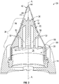
- FIG. 2 is a cross-sectioned view of the radome 12 shown in FIG. 1 illustrating the disclosed sensor waveguide system 20.
- the radome 12 acts as a protective interface between the sensor waveguide system 20 and an outside atmosphere 18.
- the sensor waveguide system 20 includes a sensor waveguide 22 defining a main body 24.
- the sensor waveguide 22 is part of an air-breathing missile 10 such as a ramjet or hypersonic missile.
- the main body 24 of the sensor waveguide 22 defines a peak 26, a base 28, an axis of rotation A-A, and a plurality of waveguide channels 32.
- the main body 24 of the sensor waveguide 22 converges from the base 28 to the peak 26 to create a predetermined tapered profile 38.
- the geometry or shape of the predetermined tapered profile 38 of the main body 24 of the sensor waveguide 22 is constrained by the outermost profile 40 of the radome 12. This is because the outermost profile 40 of the radome 12 as well as a specific position of the radome 12 within the air intake 14 of the air-breathing missile 10 significantly influences the flow of outside air that is supplied to the combustion system (not shown).
- the outermost profile 40 of the radome 12 is shaped so as not to interfere with flow of outside air entering the air intake 14. Because the sensor waveguide 22 is disposed directly underneath the radome 12, it follows that the predetermined tapered profile 38 of the main body 24 of the sensor waveguide 22 is constrained by the geometry required by the outermost profile 40 of the radome 12. In particular, as seen in FIG. 2 , the radome 12 covers the main body 24 of the sensor waveguide 22 and defines an innermost surface 46. The predetermined tapered profile 38 of the main body 24 of the sensor waveguide 22 is shaped to correspond with an innermost surface 46 of the radome 12. Accordingly, the predetermined tapered profile 38 of the main body 24 of the sensor waveguide 22 is preset or established by the aerodynamic airflow requirements of the air-breathing missile 10.
- the outermost profile 40 of the radome 12 is tapered at a thirty degree angle (or at about a thirty degree angle) and includes a frustoconical shape. Furthermore, a distal end 42 of the radome 12 terminates at a point or apex 44.
- FIGS. 1 and 2 are merely exemplary in nature and the outermost profile 40 of the radome 12 is not limited to the shape shown in the figures.
- the main body 24 of the sensor waveguide 22 is constructed of relatively lightweight materials configured to reflect electromagnetic waves such as, but not limited to, aluminum and aluminum alloys.
- the main body 24 of the sensor waveguide 22 also provides support to the radome 12.
- the main body 24 of the sensor waveguide 22 may be constructed using any number of fabrication methods such as, but not limited to, subtractive manufacturing processes such as machining, casting, compression molding, injection molding, and additive manufacturing processes.
- FIG. 3 is a cross-sectioned view of the sensor waveguide 22 and a plurality of sensors 50 that are part of a seeker antenna array 48
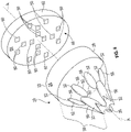
- FIG. 4 is a perspective exploded view of the sensor waveguide 22 and the seeker antenna array 48.
- the plurality of waveguide channels 32 are oriented parallel to the axis of rotation A-A of the main body 24 of the sensor waveguide 22.
- the waveguide channels 32 each include a rounded or circular cross-sectional profile 52 (seen in FIG. 4 ).
- the waveguide channels 32 are not limited to a circular cross-sectional profile. Instead, in other examples, the waveguide channels 32 include an oval, rectangular, or square cross-sectional profile.
- Each waveguide channel 32 defines an entrance 56 and an exit 58.
- the entrance 56 of each waveguide channel 32 is disposed along the predetermined tapered profile 38 of the main body 24.
- the exit 58 of each waveguide channel 32 is disposed along a lower surface 60 of the base 28 of the sensor waveguide 22, and a sensor 50 is disposed at the exit 58 of each of the plurality of waveguide channels 32.
- Each waveguide channel 32 is configured to guide an electromagnetic wave entering a corresponding waveguide channel 32 through the entrance 56, along a length L (seen in FIG. 8 ) of the corresponding waveguide channel 32, and towards a corresponding sensor 50 located at the exit 58 of the corresponding waveguide channel 32.
- the disclosed sensor waveguide 22 is not limited to any specific type of electromagnetic wave, and in some examples the seeker antenna array 48 is a multi-spectral seeker.
- the seeker antenna array 48 includes an antenna integrated printed wiring board (AiPWB) 62, where the plurality of sensors 50 are mounted to a front surface 64 of the AiPWB 62.
- the plurality of sensors 50 include radio frequency (RF) sensors, optical sensors, and infrared (IR) sensors.
- RF radio frequency
- IR infrared
- all of the sensors 50 of the seeker antenna array 48 may be RF sensors.
- the seeker antenna array 48 is a multi-spectral seeker including both optical and IR sensors.
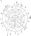
- FIG. 5 is a front view of the sensor waveguide 22 shown in FIGS. 2-4 , looking down from the peak 26 of the main body 24.
- the main body 24 of the sensor waveguide 22 defines sixteen waveguide channels 32.
- the sensor waveguide 22 is not limited to sixteen waveguide channels 32.
- the main body 24 of the sensor waveguide 22 defines at least four waveguide channels 32 (seen in FIG. 7 ) or as many as sixteen waveguide channels 32.
- the sensor waveguide 22 includes four, eight, twelve, or sixteen waveguide channels 32 depending upon the specific application and packaging constraints.
- the waveguide channels 32 are arranged into three rings R1, R2, and R3.
- the first ring R1 is an innermost ring that surrounds the axis of rotation A-A of the main body 24, the second ring R2 is located between the first ring R1 and the third ring R3, and the third ring R3 is outermost ring that is located closest to an outermost periphery 72 of the main body 24 of the sensor waveguide 22. That is, the first ring R1 is located closest to the axis of rotation A-A of the main body 24 but furthest away from the outermost periphery 72 of the main body 24 of the sensor waveguide 22.
- the third ring R3 is located closest to the outermost periphery 72 of the sensor waveguide 22 but furthest away from the axis of rotation A-A of the main body 24 of the sensor waveguide 22.
- the first ring R1, the second ring R2, and the third ring R3 are concentric with respect to one another
- the outermost or third ring R3 includes a greater number of waveguide channels 32 when compared to the remaining two rings R1 and R2.
- the third ring R3 may include eight waveguide channels 32, while the first ring R1 and the second ring R2 may include four waveguide channels 32.
- the rings R1, R2, R3 each include an equal number of waveguide channels 32.
- each ring R1, R2, R3 may include four waveguide channels 32.
- a radius of each ring R1, R2, R3 represents a radial distance between circumferences.
- a radius r of the third ring R3 is measured between an inner circumference 86 and an outer circumference 88 of the third ring R3.
- each of the rings R1, R2, R3 include equal radii r.
- FIG. 6 illustrates the first ring R1 including a first radius r 1 , the second ring R2 including a second radius r 2 , and the third ring R3 including a third radius r 3 .
- the first radius r 1 of the first ring R1 is equal to the third radius r 3 of the third ring R3, and the second radius r 2 of the second ring R2 is greater than the first radius r 1 and the third radius r 3 .
- the first ring R1 surrounds the axis of rotation A-A of the main body 24 of the sensor waveguide 22.
- the first ring R1 includes a plurality of first waveguide channels 32A that are positioned in unique locations around the first ring R1.
- the plurality of first waveguide channels 32A are each positioned equidistant from the axis of rotation A-A of the main body 24 of the sensor waveguide 22.
- the plurality of first waveguide channels 32A are also positioned equidistant with respect to one another and are ninety degrees (or about ninety degrees) apart from one another.
- one of the first waveguide channels 32A is positioned at a 12 o'clock position 74 of the main body 24, another first waveguide channel 32A is positioned a 3 o'clock position 76, another first waveguide channel 32A is positioned at a 6 o'clock position 78, and the remaining first waveguide channel 32A is positioned at a nine o'clock position 80 of the main body 24.
- the second ring R2 surrounds the first ring R1 and includes a plurality of second waveguide channels 32B positioned in unique locations around the second ring R2.
- the plurality of second waveguide channels 32B are each positioned equidistant from the axis of rotation A-A of the main body 24 of the sensor waveguide 22.
- the plurality of second waveguide channels 32B are also positioned equidistant with respect to one another.
- one of the second waveguide channels 32B is positioned at a 12 o'clock position 74 of the main body 24, another second waveguide channel 32B is positioned a 3 o'clock position 76, another second waveguide channel 32B is positioned at a 6 o'clock position 78, and the remaining second waveguide channel 32B is positioned at a nine o'clock position 80 of the main body 24.
- the plurality of first waveguide channels 32A are radially aligned with the second plurality of waveguide channels 32B.
- the plurality of first waveguide channels 32A are arranged in a cross pattern where each first waveguide channel 32A is positioned ninety degrees (or about ninety degrees) from the remaining three first waveguide channels 32A.
- the plurality of second waveguide channels 32B are arranged in a cross pattern where each second waveguide channel 32B is positioned ninety degrees (or about ninety degrees) from the remaining three second waveguide channels 32B.
- a ray 82 extending radially from the axis of rotation A-A of the main body 24 of the sensor waveguide 22 intersects with one of the first waveguide channels 32A and one of the second waveguide channels 32B.
- the third ring R3 surrounds the second ring R2 and includes a plurality of third waveguide channels 32C positioned in unique locations around the third ring R3.
- the plurality of third waveguide channels 32C are each positioned equidistant from the axis of rotation A-A of the main body 24 of the sensor waveguide 22.
- the plurality of third waveguide channels 32C are also positioned equidistant with respect to one another.
- the third waveguide channels 32C are not radially aligned with the first waveguide channels 32A or the second waveguide channels 32B. Instead, each of the third waveguide channels 32C are positioned forty-five degrees (or about forty-five degrees) apart from one another. In some examples like the example shown in FIG.
- two third waveguide channels 32C are positioned between the 12 o'clock position 74 and the 3 o'clock position 76, two third waveguide channels 32C are positioned between the 3 o'clock position 76 and the six o'clock position 78, two third waveguide channels 32C are positioned between the six o'clock position 78 and the nine o'clock position 80, and two third waveguide channels 32C are positioned between the nine o'clock position 80 and the 12 o'clock position 74.
- FIG. 7 is yet another example of the sensor waveguide 22, where the main body 24 only defines four waveguide channels 32.
- each waveguide channel 32 includes four sensors 50. Each sensor 50 is disposed at the exit 58 of a respective of the waveguide channel 32.
- the waveguide channels 32 are arranged in four quadrants Q1, Q2, Q3, and Q4, where a single waveguide channel 32 is disposed within each quadrant Q1, Q2, Q3, Q4.
- Each waveguide channel 32 is positioned equidistant from the axis of rotation A-A of the main body 24 of the sensor waveguide 22.
- the plurality of waveguide channels 32 are also positioned equidistant with respect to one another.
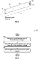
- FIG. 8 is an illustration of an electromagnetic wave E being transmitted along the length L of one of the waveguide channels 32 of the sensor waveguide 22.
- the waveguide channel 32 receives the electromagnetic wave E at the entrance 56.
- the electromagnetic wave E is transmitted along the length L of the waveguide channel 32.
- the electromagnetic wave E is reflected off an inner surface 84 of the waveguide channel 32 towards the exit 58 of the waveguide channel 32.
- FIG. 9 illustrates a process flow diagram of a method 200 for guiding the electromagnetic wave E (shown in FIG. 8 ) by the sensor waveguide system 20.
- the method 200 begins at block 202.
- a waveguide channel 32 receives the electromagnetic wave E, where the waveguide channel 32 is part of the sensor waveguide system 20.
- the sensor waveguide 22 includes the main body 24 defining the peak 26, the base 28, the axis of rotation A-A, and the plurality of waveguide channels 32.
- the plurality of waveguide channels 32 are oriented parallel to the axis of rotation A-A of the sensor waveguide 22, and the main body 24 converges from the base 28 to the peak 26 to create the predetermined tapered profile 38.
- the method 200 may then proceed to block 204.
- the electromagnetic wave E ( FIG. 8 ) is transmitting along the length L of the waveguide channel 32. Specifically, the electromagnetic wave E reflects off the inner surface 84 of the waveguide channel 32, and towards the exit 58 of the waveguide channel 32. The method 200 may then proceed to block 206.
- the electromagnetic wave E is received by the sensor 50 disposed at the exit 58 of the waveguide channel 32.
- the method 200 may then terminate.
- the disclosed sensor waveguide system provides various technical effects and benefits. Specifically, the sensor waveguide system provides a low-cost, relatively lightweight approach for guiding electromagnetic signals to an antenna seeker array. Furthermore, the main body of the sensor waveguide includes a predetermined tapered profile that does not interfere with or adversely affect the flow of outside air into the air intake of an air-breathing missile. The disclosed sensor waveguide also provide support to a radome that covers the sensor wagi
- a sensor waveguide system (20), the sensor waveguide system (20) comprises: a sensor waveguide (22) including a main body (24) defining a peak (26), a base (28), an axis of rotation (A-A), and a plurality of waveguide channels (32), wherein the main body (24) converges from the base (28) to the peak (26) to create a predetermined tapered profile (38), and wherein the plurality of waveguide channels (32) are oriented parallel to the axis of rotation (A-A) of the sensor waveguide (22) and each waveguide channel (32) defines an exit (58) disposed at the base (28) of the main body (24); and a plurality of sensors (50), wherein a sensor (50) is disposed at the exit (58) of each of the plurality of waveguide channels (32).
- the sensor waveguide system (20) of the preceding paragraph further comprises a radome (12) covering the main body (24) of the sensor waveguide (22), wherein the radome (12) defines an innermost surface (46).
- the predetermined tapered profile (38) of the main body (24) of the sensor waveguide (22) is shaped to correspond with the innermost surface (46) of the radome (12).
- a plurality of first waveguide channels (32A) are positioned around a first ring (R1), wherein the first ring (R1) surrounds the axis of rotation (A-A) of the main body (24) of the sensor waveguide (22).
- the plurality of first waveguide channels (32A) are positioned equidistant from the axis of rotation (A-A) of the main body (24) of the sensor waveguide (22).
- a plurality of second waveguide channels (32B) are positioned around a second ring (R2), wherein the second ring (R2) surrounds the first ring (R1).
- the plurality of second waveguide channels (32B) are positioned equidistant from the axis of rotation (A-A) of the main body (24) of the sensor waveguide (22).
- the plurality of first waveguide channels (32A) and the plurality of second waveguide channels (32B) are radially aligned with one another.
- a plurality of third waveguide channels (32C) are positioned around a third ring (R3), and wherein the third ring (R3) surrounds the second ring (R2).
- the plurality of third waveguide channels (32C) are positioned equidistant from the axis of rotation (A-A) of the main body (24) of the sensor waveguide (22).
- the first ring (R1), the second ring (R2), and the third ring (R3) are concentric with respect to one another.
- the first ring (R1), the second ring (R2), and the third ring (R3) each include an equal number of waveguide channels (32).
- the main body (24) of the sensor waveguide (22) defines at least four waveguide channels (32).
- the main body (24) is constructed of at least one of the following: aluminum and an aluminum alloy.
- the plurality of sensors (50) include at least one of the following: radio frequency (RF) sensors, optical sensors, and infrared (IR) sensors.
- RF radio frequency
- IR infrared
- the plurality of sensors (50) are part of a seeker antenna array (48).
- An air-breathing missile (10) comprises: an air intake (14); a radome (12) defining an innermost surface (46), wherein the air intake (14) surrounds the radome (12); and a sensor waveguide system (20), comprising: a sensor waveguide (22) including a main body (24) defining a peak (26), a base (28), an axis of rotation (A-A), and a plurality of waveguide channels (32), wherein the main body (24) converges from the base (28) to the peak (26) to create a predetermined tapered profile (38), and wherein the plurality of waveguide channels (32) are oriented parallel to the axis of rotation (A-A) of the sensor waveguide (22) and each waveguide channel defines an exit (58) disposed at the base (28) of the main body (24); and a plurality of sensors (50), wherein a sensor (50) is disposed at the exit (58) of each of the plurality of waveguide channels (32).
- the predetermined tapered profile (38) of the main body (24) of the sensor waveguide (22) is shaped to correspond with the innermost surface (46) of the radome (12).
- the electromagnetic wave (E) reflects off an inner surface (84) of the waveguide channel (32) towards the exit (58) of the waveguide channel (32).
Landscapes
- Engineering & Computer Science (AREA)
- Chemical & Material Sciences (AREA)
- Combustion & Propulsion (AREA)
- General Engineering & Computer Science (AREA)
- Physics & Mathematics (AREA)
- Aviation & Aerospace Engineering (AREA)
- Astronomy & Astrophysics (AREA)
- General Physics & Mathematics (AREA)
- Remote Sensing (AREA)
- Electromagnetism (AREA)
- Details Of Aerials (AREA)
- Aiming, Guidance, Guns With A Light Source, Armor, Camouflage, And Targets (AREA)
Abstract
Description
- The present disclosure relates to a sensor waveguide system for a seeker antenna array. More particularly, the present disclosure is directed towards a sensor waveguide having a main body that defines a peak and a base, where the main body converges from the base to the peak to create a predetermined taper profile.
- Ramjets operate by ingesting intake air traveling at relatively low speeds and then expelling the intake air at a much higher speed, where the difference in speed results in a forward thrust. Ramjets are not capable of producing the forward thrust at lower speeds, and therefore require propulsion assistance until they reach an operating speed. For example, a ramjet missile is boosted to an operating speed where forward thrust is produced by a rocket engine or, alternatively, by another aircraft. It is to be appreciated that ramjets compress the intake air using the forward speed of the air vehicle, and therefore do not require a compressor. Accordingly, special attention is usually given when designing the intake of a ramjet.
- A missile typically employs optical, infrared (IR), radio frequency (RF), or multi-spectral seekers for detecting and guiding a missile toward an intended target. The seeker includes an antenna array that is affixed in a nose cone of a missile, which is the foremost portion of the missile. Specifically, the antenna array is housed within an enclosure. The enclosure housing the antenna array is referred to as a radome, which protects the antenna from aerodynamic loads and extreme temperatures that are experienced during flight. The geometry as well as the positioning of the radome may significantly influence the flow of outside air into the intake of the ramjet. Accordingly, the geometry of the radome is shaped so as not to interfere with the outside air that enters the ramjet though the intake.
- A sensor waveguide system is disclosed, and includes a sensor waveguide including a main body defining a peak, a base, an axis of rotation, and a plurality of waveguide channels. The main body converges from the base to the peak to create a predetermined tapered profile. The plurality of waveguide channels are oriented parallel to the axis of rotation of the sensor waveguide and each waveguide channel defines an exit disposed at the base of the main body. The sensor waveguide system also includes a plurality of sensors, where a sensor is disposed at the exit of each of the plurality of waveguide channels.
- An air-breathing missile is disclosed and includes an air intake, a radome defining an innermost surface where the air intake surrounds the radome, and a sensor waveguide system. The sensor waveguide system includes sensor waveguide including a main body defining a peak, a base, an axis of rotation, and a plurality of waveguide channels. The main body converges from the base to the peak to create a predetermined tapered profile. The plurality of waveguide channels are oriented parallel to the axis of rotation of the sensor waveguide and each waveguide channel defines an exit disposed at the base of the main body. The sensor waveguide system also includes a plurality of sensors, where a sensor is disposed at the exit of each of the plurality of waveguide channels.
- A method for guiding an electromagnetic wave by a sensor waveguide system including a sensor waveguide is disclosed. The method includes receiving, by a waveguide channel, an electromagnetic wave. The sensor waveguide includes a main body defining a peak, a base, an axis of rotation, and a plurality of waveguide channels. The plurality of waveguide channels are oriented parallel to the axis of rotation of the sensor waveguide and the main body converges from the base to the peak to create a predetermined tapered profile. The method also includes transmitting the electromagnetic wave along a length of the waveguide channel, where each of the plurality of waveguide channels of the sensor waveguide define an exit disposed at the base of the main body. Finally, the method includes receiving the electromagnetic wave by a sensor. The sensor is disposed at the exit of the waveguide channel.
- The features, functions, and advantages that have been discussed may be achieved independently in various examples or may be combined in other examples further details of which can be seen with reference to the following description and drawings.
- The drawings described herein are for illustration purposes only and are not intended to limit the scope of the present disclosure in any way.
-
FIG. 1 is a perspective view of a front end of a ramjet missile having a radome; -
FIG. 2 is a cross-sectioned view of the radome shown inFIG. 1 , where the disclosed sensor waveguide is located within the radome; -
FIG. 3 is a cross sectioned view of the sensor waveguide and a seeker antenna array; -
FIG. 4 is a perspective, exploded view of the sensor waveguide and the seeker antenna array shown inFIG. 3 ; -
FIG. 5 is a top view of the sensor waveguide; -
FIG. 6 is a top view of an alternative example of the sensor waveguide; -
FIG. 7 is a top view of yet another example of the sensor waveguide; -
FIG. 8 is a schematic diagram of an electromagnetic wave being transmitted along a waveguide channel that is part of the sensor waveguide; and -
FIG. 9 is a process flow diagram illustrating a method for guiding an electromagnetic wave by the sensor waveguide system. - The present disclosure is directed towards a sensor waveguide system for a seeker antenna array. The sensor waveguide system includes a sensor waveguide having a main body. The main body of the sensor waveguide defines a peak and a base, where the main body converges from the base to the peak to create a predetermined tapered profile. The main body of the sensor waveguide also defines an axis of rotation and a plurality of waveguide channels, where the waveguide channels are oriented parallel to the axis of rotation of the main body of the waveguide. The sensor waveguide system also includes a plurality of sensors, where a sensor is disposed at a corresponding exit of each of the plurality of waveguides.
- In some examples, the sensor waveguide system is part of an air-breathing missile such as a ramjet or a hypersonic missile. The air-breathing missile includes a radome installed at a front end, and the sensor waveguide is positioned underneath the radome. It is to be appreciated that an air-breathing missile employs external or outside air for combustion. As a result, the air-breathing missile may have specific aerodynamic airflow requirements to ensure that the air-breathing missile's combustion system receives the appropriate airflow required for combustion. The outer profile of the radome is dictated by the aerodynamic airflow requirements of the air-breathing missile. Since the disclosed sensor waveguide is located underneath the radome, it follows that the predetermined tapered profile of the main body of the sensor waveguide is also dictated by the aerodynamic airflow requirements of the air-breathing missile.
- The following description is merely exemplary in nature and is not intended to limit the present disclosure, application, or uses.
- Referring to
FIG. 1 , afront end 8 of an exemplary air-breathing missile 10 is shown. Aradome 12 is positioned at thefront end 8 of the air-breathingmissile 10, and anair intake 14 of the air-breathingmissile 10 surrounds theradome 12. Theair intake 14 is configured to capture the airflow required by a combustion system (not shown) of the air-breathing missile 10.FIG. 2 is a cross-sectioned view of theradome 12 shown inFIG. 1 illustrating the disclosedsensor waveguide system 20. Referring to bothFIGS. 1 and2 , theradome 12 acts as a protective interface between thesensor waveguide system 20 and anoutside atmosphere 18. Thesensor waveguide system 20 includes asensor waveguide 22 defining amain body 24. In some examples including the example shown inFIG. 1 , thesensor waveguide 22 is part of an air-breathing missile 10 such as a ramjet or hypersonic missile. - Referring specifically to
FIG. 2 , themain body 24 of thesensor waveguide 22 defines apeak 26, abase 28, an axis of rotation A-A, and a plurality ofwaveguide channels 32. Themain body 24 of thesensor waveguide 22 converges from thebase 28 to thepeak 26 to create a predeterminedtapered profile 38. Referring to bothFIGS. 1 and2 , the geometry or shape of the predetermined taperedprofile 38 of themain body 24 of thesensor waveguide 22 is constrained by theoutermost profile 40 of theradome 12. This is because theoutermost profile 40 of theradome 12 as well as a specific position of theradome 12 within theair intake 14 of the air-breathingmissile 10 significantly influences the flow of outside air that is supplied to the combustion system (not shown). Accordingly, theoutermost profile 40 of theradome 12 is shaped so as not to interfere with flow of outside air entering theair intake 14. Because thesensor waveguide 22 is disposed directly underneath theradome 12, it follows that the predeterminedtapered profile 38 of themain body 24 of thesensor waveguide 22 is constrained by the geometry required by theoutermost profile 40 of theradome 12. In particular, as seen inFIG. 2 , theradome 12 covers themain body 24 of thesensor waveguide 22 and defines aninnermost surface 46. The predeterminedtapered profile 38 of themain body 24 of thesensor waveguide 22 is shaped to correspond with aninnermost surface 46 of theradome 12. Accordingly, the predetermined taperedprofile 38 of themain body 24 of thesensor waveguide 22 is preset or established by the aerodynamic airflow requirements of the air-breathingmissile 10. - In some examples including the example shown in
FIGS. 1 and2 , theoutermost profile 40 of theradome 12 is tapered at a thirty degree angle (or at about a thirty degree angle) and includes a frustoconical shape. Furthermore, adistal end 42 of theradome 12 terminates at a point or apex 44. However, it is to be appreciated that theFIGS. 1 and2 are merely exemplary in nature and theoutermost profile 40 of theradome 12 is not limited to the shape shown in the figures. - Referring to
FIG. 2 , themain body 24 of thesensor waveguide 22 is constructed of relatively lightweight materials configured to reflect electromagnetic waves such as, but not limited to, aluminum and aluminum alloys. Themain body 24 of thesensor waveguide 22 also provides support to theradome 12. Themain body 24 of thesensor waveguide 22 may be constructed using any number of fabrication methods such as, but not limited to, subtractive manufacturing processes such as machining, casting, compression molding, injection molding, and additive manufacturing processes. -
FIG. 3 is a cross-sectioned view of thesensor waveguide 22 and a plurality ofsensors 50 that are part of aseeker antenna array 48, andFIG. 4 is a perspective exploded view of thesensor waveguide 22 and theseeker antenna array 48. Although the figures illustrate theseeker antenna array 48 as part of an air-breathingmissile 10, theseeker antenna array 48 may be installed on other components as well such as, for example, an aircraft wing. Referring toFIGS. 2 ,3 , and4 , the plurality ofwaveguide channels 32 are oriented parallel to the axis of rotation A-A of themain body 24 of thesensor waveguide 22. In some examples, thewaveguide channels 32 each include a rounded or circular cross-sectional profile 52 (seen inFIG. 4 ). However, it is to be appreciated that thewaveguide channels 32 are not limited to a circular cross-sectional profile. Instead, in other examples, thewaveguide channels 32 include an oval, rectangular, or square cross-sectional profile. - Each
waveguide channel 32 defines anentrance 56 and anexit 58. Theentrance 56 of eachwaveguide channel 32 is disposed along the predetermined taperedprofile 38 of themain body 24. Referring specifically toFIG. 3 , theexit 58 of eachwaveguide channel 32 is disposed along alower surface 60 of thebase 28 of thesensor waveguide 22, and asensor 50 is disposed at theexit 58 of each of the plurality ofwaveguide channels 32. - Each
waveguide channel 32 is configured to guide an electromagnetic wave entering acorresponding waveguide channel 32 through theentrance 56, along a length L (seen inFIG. 8 ) of the correspondingwaveguide channel 32, and towards a correspondingsensor 50 located at theexit 58 of the correspondingwaveguide channel 32. It is to be appreciated that the disclosedsensor waveguide 22 is not limited to any specific type of electromagnetic wave, and in some examples theseeker antenna array 48 is a multi-spectral seeker. Referring specifically toFIGS. 3 and4 , theseeker antenna array 48 includes an antenna integrated printed wiring board (AiPWB) 62, where the plurality ofsensors 50 are mounted to afront surface 64 of theAiPWB 62. The plurality ofsensors 50 include radio frequency (RF) sensors, optical sensors, and infrared (IR) sensors. In some examples, all of thesensors 50 of theseeker antenna array 48 may be RF sensors. In other examples, theseeker antenna array 48 is a multi-spectral seeker including both optical and IR sensors. -
FIG. 5 is a front view of thesensor waveguide 22 shown inFIGS. 2-4 , looking down from thepeak 26 of themain body 24. In some examples including the example shown inFIG. 5 , themain body 24 of thesensor waveguide 22 defines sixteenwaveguide channels 32. However, it is to be appreciated that thesensor waveguide 22 is not limited to sixteenwaveguide channels 32. Instead, themain body 24 of thesensor waveguide 22 defines at least four waveguide channels 32 (seen inFIG. 7 ) or as many as sixteenwaveguide channels 32. Specifically, thesensor waveguide 22 includes four, eight, twelve, or sixteenwaveguide channels 32 depending upon the specific application and packaging constraints. - As seen in
FIG. 5 , thewaveguide channels 32 are arranged into three rings R1, R2, and R3. The first ring R1 is an innermost ring that surrounds the axis of rotation A-A of themain body 24, the second ring R2 is located between the first ring R1 and the third ring R3, and the third ring R3 is outermost ring that is located closest to anoutermost periphery 72 of themain body 24 of thesensor waveguide 22. That is, the first ring R1 is located closest to the axis of rotation A-A of themain body 24 but furthest away from theoutermost periphery 72 of themain body 24 of thesensor waveguide 22. Similarly, the third ring R3 is located closest to theoutermost periphery 72 of thesensor waveguide 22 but furthest away from the axis of rotation A-A of themain body 24 of thesensor waveguide 22. The first ring R1, the second ring R2, and the third ring R3 are concentric with respect to one another - In some examples including the example shown in
FIG. 5 , the outermost or third ring R3 includes a greater number ofwaveguide channels 32 when compared to the remaining two rings R1 and R2. As shown, the third ring R3 may include eightwaveguide channels 32, while the first ring R1 and the second ring R2 may include fourwaveguide channels 32. However, in alternative examples like the example shown inFIG. 6 , the rings R1, R2, R3 each include an equal number ofwaveguide channels 32. For example, as shown inFIG. 6 , each ring R1, R2, R3 may include fourwaveguide channels 32. - Referring to
FIG. 5 , a radius of each ring R1, R2, R3 represents a radial distance between circumferences. For example, a radius r of the third ring R3 is measured between aninner circumference 86 and anouter circumference 88 of the third ring R3. In some examples like the example shown inFIG. 5 , each of the rings R1, R2, R3 include equal radii r. In contrast,FIG. 6 illustrates the first ring R1 including a first radius r1, the second ring R2 including a second radius r2, and the third ring R3 including a third radius r3. The first radius r1 of the first ring R1 is equal to the third radius r3 of the third ring R3, and the second radius r2 of the second ring R2 is greater than the first radius r1 and the third radius r3. - Referring back to
FIG. 5 , the first ring R1 surrounds the axis of rotation A-A of themain body 24 of thesensor waveguide 22. The first ring R1 includes a plurality offirst waveguide channels 32A that are positioned in unique locations around the first ring R1. Specifically, the plurality offirst waveguide channels 32A are each positioned equidistant from the axis of rotation A-A of themain body 24 of thesensor waveguide 22. Furthermore, as seen inFIG. 5 , the plurality offirst waveguide channels 32A are also positioned equidistant with respect to one another and are ninety degrees (or about ninety degrees) apart from one another. That is, one of thefirst waveguide channels 32A is positioned at a 12o'clock position 74 of themain body 24, anotherfirst waveguide channel 32A is positioned a 3o'clock position 76, anotherfirst waveguide channel 32A is positioned at a 6o'clock position 78, and the remainingfirst waveguide channel 32A is positioned at a nineo'clock position 80 of themain body 24. - Continuing to refer to
FIG. 5 , the second ring R2 surrounds the first ring R1 and includes a plurality ofsecond waveguide channels 32B positioned in unique locations around the second ring R2. The plurality ofsecond waveguide channels 32B are each positioned equidistant from the axis of rotation A-A of themain body 24 of thesensor waveguide 22. The plurality ofsecond waveguide channels 32B are also positioned equidistant with respect to one another. Similar to thefirst waveguide channels 32A, one of thesecond waveguide channels 32B is positioned at a 12o'clock position 74 of themain body 24, anothersecond waveguide channel 32B is positioned a 3o'clock position 76, anothersecond waveguide channel 32B is positioned at a 6o'clock position 78, and the remainingsecond waveguide channel 32B is positioned at a nineo'clock position 80 of themain body 24. - In some examples like the example shown in
FIG. 5 , the plurality offirst waveguide channels 32A are radially aligned with the second plurality ofwaveguide channels 32B. In other words, the plurality offirst waveguide channels 32A are arranged in a cross pattern where eachfirst waveguide channel 32A is positioned ninety degrees (or about ninety degrees) from the remaining threefirst waveguide channels 32A. Similarly, the plurality ofsecond waveguide channels 32B are arranged in a cross pattern where eachsecond waveguide channel 32B is positioned ninety degrees (or about ninety degrees) from the remaining threesecond waveguide channels 32B. Thus, aray 82 extending radially from the axis of rotation A-A of themain body 24 of thesensor waveguide 22 intersects with one of thefirst waveguide channels 32A and one of thesecond waveguide channels 32B. - The third ring R3 surrounds the second ring R2 and includes a plurality of
third waveguide channels 32C positioned in unique locations around the third ring R3. The plurality ofthird waveguide channels 32C are each positioned equidistant from the axis of rotation A-A of themain body 24 of thesensor waveguide 22. The plurality ofthird waveguide channels 32C are also positioned equidistant with respect to one another. However, thethird waveguide channels 32C are not radially aligned with thefirst waveguide channels 32A or thesecond waveguide channels 32B. Instead, each of thethird waveguide channels 32C are positioned forty-five degrees (or about forty-five degrees) apart from one another. In some examples like the example shown inFIG. 5 , twothird waveguide channels 32C are positioned between the 12o'clock position 74 and the 3o'clock position 76, twothird waveguide channels 32C are positioned between the 3o'clock position 76 and the sixo'clock position 78, twothird waveguide channels 32C are positioned between the sixo'clock position 78 and the nineo'clock position 80, and twothird waveguide channels 32C are positioned between the nineo'clock position 80 and the 12o'clock position 74. -
FIG. 7 is yet another example of thesensor waveguide 22, where themain body 24 only defines fourwaveguide channels 32. In some examples like the example shown inFIG. 7 , eachwaveguide channel 32 includes foursensors 50. Eachsensor 50 is disposed at theexit 58 of a respective of thewaveguide channel 32. In some examples like the example shown inFIG. 7 , thewaveguide channels 32 are arranged in four quadrants Q1, Q2, Q3, and Q4, where asingle waveguide channel 32 is disposed within each quadrant Q1, Q2, Q3, Q4. Eachwaveguide channel 32 is positioned equidistant from the axis of rotation A-A of themain body 24 of thesensor waveguide 22. The plurality ofwaveguide channels 32 are also positioned equidistant with respect to one another. -
FIG. 8 is an illustration of an electromagnetic wave E being transmitted along the length L of one of thewaveguide channels 32 of thesensor waveguide 22. Thewaveguide channel 32 receives the electromagnetic wave E at theentrance 56. The electromagnetic wave E is transmitted along the length L of thewaveguide channel 32. Specifically, the electromagnetic wave E is reflected off aninner surface 84 of thewaveguide channel 32 towards theexit 58 of thewaveguide channel 32. -
FIG. 9 illustrates a process flow diagram of amethod 200 for guiding the electromagnetic wave E (shown inFIG. 8 ) by thesensor waveguide system 20. Referring generally toFIGS. 2 ,3 ,8, and 9 , themethod 200 begins atblock 202. Inblock 202, awaveguide channel 32 receives the electromagnetic wave E, where thewaveguide channel 32 is part of thesensor waveguide system 20. As shown inFIGS. 2 and3 , thesensor waveguide 22 includes themain body 24 defining thepeak 26, thebase 28, the axis of rotation A-A, and the plurality ofwaveguide channels 32. As mentioned above, the plurality ofwaveguide channels 32 are oriented parallel to the axis of rotation A-A of thesensor waveguide 22, and themain body 24 converges from the base 28 to the peak 26 to create the predetermined taperedprofile 38. Themethod 200 may then proceed to block 204. - In
block 204, the electromagnetic wave E (FIG. 8 ) is transmitting along the length L of thewaveguide channel 32. Specifically, the electromagnetic wave E reflects off theinner surface 84 of thewaveguide channel 32, and towards theexit 58 of thewaveguide channel 32. Themethod 200 may then proceed to block 206. - In
block 206, the electromagnetic wave E is received by thesensor 50 disposed at theexit 58 of thewaveguide channel 32. Themethod 200 may then terminate. - Referring generally to the figures, the disclosed sensor waveguide system provides various technical effects and benefits. Specifically, the sensor waveguide system provides a low-cost, relatively lightweight approach for guiding electromagnetic signals to an antenna seeker array. Furthermore, the main body of the sensor waveguide includes a predetermined tapered profile that does not interfere with or adversely affect the flow of outside air into the air intake of an air-breathing missile. The disclosed sensor waveguide also provide support to a radome that covers the sensor wagi
- Further illustrative and non-exclusive examples according to, the disclosure are described in the following paragraphs:
- A sensor waveguide system (20), the sensor waveguide system (20) comprises: a sensor waveguide (22) including a main body (24) defining a peak (26), a base (28), an axis of rotation (A-A), and a plurality of waveguide channels (32), wherein the main body (24) converges from the base (28) to the peak (26) to create a predetermined tapered profile (38), and wherein the plurality of waveguide channels (32) are oriented parallel to the axis of rotation (A-A) of the sensor waveguide (22) and each waveguide channel (32) defines an exit (58) disposed at the base (28) of the main body (24); and a plurality of sensors (50), wherein a sensor (50) is disposed at the exit (58) of each of the plurality of waveguide channels (32).
- Optionally, the sensor waveguide system (20) of the preceding paragraph, further comprises a radome (12) covering the main body (24) of the sensor waveguide (22), wherein the radome (12) defines an innermost surface (46).
- Optionally, in the sensor waveguide system (20) of either of the two preceding paragraphs, the predetermined tapered profile (38) of the main body (24) of the sensor waveguide (22) is shaped to correspond with the innermost surface (46) of the radome (12).
- Optionally, in the sensor waveguide system (20) of any of the three preceding paragraphs, a plurality of first waveguide channels (32A) are positioned around a first ring (R1), wherein the first ring (R1) surrounds the axis of rotation (A-A) of the main body (24) of the sensor waveguide (22).
- Optionally, in the sensor waveguide system (20) of any of four preceding earlier paragraphs, the plurality of first waveguide channels (32A) are positioned equidistant from the axis of rotation (A-A) of the main body (24) of the sensor waveguide (22).
- Optionally, in the sensor waveguide system (20) of any of the five preceding paragraphs, a plurality of second waveguide channels (32B) are positioned around a second ring (R2), wherein the second ring (R2) surrounds the first ring (R1).
- Optionally, in the sensor waveguide system (20) of any of the six preceding paragraphs, the plurality of second waveguide channels (32B) are positioned equidistant from the axis of rotation (A-A) of the main body (24) of the sensor waveguide (22).
- Optionally, in the sensor waveguide system (20) of any of the seven preceding paragraphs, the plurality of first waveguide channels (32A) and the plurality of second waveguide channels (32B) are radially aligned with one another.
- Optionally, in the sensor waveguide system (20) of any of the eight preceding paragraphs, a plurality of third waveguide channels (32C) are positioned around a third ring (R3), and wherein the third ring (R3) surrounds the second ring (R2).
- Optionally, in the sensor waveguide system (20) of any of the nine preceding paragraphs, the plurality of third waveguide channels (32C) are positioned equidistant from the axis of rotation (A-A) of the main body (24) of the sensor waveguide (22).
- Optionally, in the sensor waveguide system (20) of any of the ten preceding paragraphs, the first ring (R1), the second ring (R2), and the third ring (R3) are concentric with respect to one another.
- Optionally, in the sensor waveguide system (20) of any of the eleven preceding paragraphs, the first ring (R1), the second ring (R2), and the third ring (R3) each include an equal number of waveguide channels (32).
- Optionally, in the sensor waveguide system (20) of any of the twelve preceding paragraphs, the main body (24) of the sensor waveguide (22) defines at least four waveguide channels (32).
- Optionally, in the sensor waveguide system (20) of any of the thirteen preceding paragraphs, the main body (24) is constructed of at least one of the following: aluminum and an aluminum alloy.
- Optionally, in the sensor waveguide system (20) of any of the fourteen preceding paragraphs, the plurality of sensors (50) include at least one of the following: radio frequency (RF) sensors, optical sensors, and infrared (IR) sensors.
- Optionally, in the sensor waveguide system (20) of any of the fifteen preceding paragraphs, the plurality of sensors (50) are part of a seeker antenna array (48).
- An air-breathing missile (10), comprises: an air intake (14); a radome (12) defining an innermost surface (46), wherein the air intake (14) surrounds the radome (12); and a sensor waveguide system (20), comprising: a sensor waveguide (22) including a main body (24) defining a peak (26), a base (28), an axis of rotation (A-A), and a plurality of waveguide channels (32), wherein the main body (24) converges from the base (28) to the peak (26) to create a predetermined tapered profile (38), and wherein the plurality of waveguide channels (32) are oriented parallel to the axis of rotation (A-A) of the sensor waveguide (22) and each waveguide channel defines an exit (58) disposed at the base (28) of the main body (24); and a plurality of sensors (50), wherein a sensor (50) is disposed at the exit (58) of each of the plurality of waveguide channels (32).
- Optionally, in the air-breathing missile (10) of the preceding paragraph, the predetermined tapered profile (38) of the main body (24) of the sensor waveguide (22) is shaped to correspond with the innermost surface (46) of the radome (12).
- A method (200) for guiding an electromagnetic wave (E) by a sensor waveguide system (20) including a sensor waveguide (22), the method (200) comprises: receiving (202), by a waveguide channel (32), an electromagnetic wave (E), wherein the sensor waveguide (22) includes a main body (24) defining a peak (26), a base (28), an axis of rotation (A-A), and a plurality of waveguide channels (32), wherein the plurality of waveguide channels (32) are oriented parallel to the axis of rotation (A-A) of the sensor waveguide (22) and the main body (24) converges from the base (28) to the peak (26) to create a predetermined tapered profile (38); transmitting (204) the electromagnetic wave (E) along a length (L) of the waveguide channel (32), wherein each of the plurality of waveguide channels (32) of the sensor waveguide (22) define an exit (58) disposed at the base (28) of the main body (24); and receiving (206) the electromagnetic wave (E) by a sensor (50), wherein the sensor (50) is disposed at the exit (58) of the waveguide channel (32).
- Optionally, in the method of the preceding paragraph, the electromagnetic wave (E) reflects off an inner surface (84) of the waveguide channel (32) towards the exit (58) of the waveguide channel (32).
- The description of the present disclosure is merely exemplary in nature and variations that do not depart from the gist of the present disclosure are intended to be within the scope of the present disclosure. Such variations are not to be regarded as a departure from the spirit and scope of the present disclosure.
Claims (15)
- A sensor waveguide system (20) comprising:a sensor waveguide (22) including a main body (24) defining a peak (26), a base (28), an axis of rotation (A-A), and a plurality of waveguide channels (32), wherein the main body (24) converges from the base (28) to the peak (26) to create a predetermined tapered profile (38), and wherein the plurality of waveguide channels (32) are oriented parallel to the axis of rotation (A-A) of the sensor waveguide (22) and each waveguide channel (32) defines an exit (58) disposed at the base (28) of the main body (24); anda plurality of sensors (50), wherein a sensor (50) is disposed at the exit (58) of each of the plurality of waveguide channels (32).
- The sensor waveguide system (20) of claim 1, further comprising a radome (12) covering the main body (24) of the sensor waveguide (22), wherein the radome (12) defines an innermost surface (46).
- The sensor waveguide system (20) of claim 2, wherein the predetermined tapered profile (38) of the main body (24) of the sensor waveguide (22) is shaped to correspond with the innermost surface (46) of the radome (12).
- The sensor waveguide system (20) of any one of claims 1-3, wherein:a plurality of first waveguide channels (32A) are positioned around a first ring (R1);the first ring (R1) surrounds the axis of rotation (A-A) of the main body (24) of the sensor waveguide (22); and, optionally,the plurality of first waveguide channels (32A) are positioned equidistant from the axis of rotation (A-A) of the main body (24) of the sensor waveguide (22).
- The sensor waveguide system (20) of claim 4, wherein a plurality of second waveguide channels (32B) are positioned around a second ring (R2), wherein the second ring (R2) surrounds the first ring (R1).
- The sensor waveguide system (20) of claim 5, wherein the plurality of second waveguide channels (32B) are positioned equidistant from the axis of rotation (A-A) of the main body (24) of the sensor waveguide (22).
- The sensor waveguide system (20) of claim 5 or 6, wherein the plurality of first waveguide channels (32A) and the plurality of second waveguide channels (32B) are radially aligned with one another.
- The sensor waveguide system (20) of any one of claims 5-7, wherein:a plurality of third waveguide channels (32C) are positioned around a third ring (R3);the third ring (R3) surrounds the second ring (R2); and, optionally,the plurality of third waveguide channels (32C) are positioned equidistant from the axis of rotation (A-A) of the main body (24) of the sensor waveguide (22).
- The sensor waveguide system (20) of claim 8, wherein the first ring (R1), the second ring (R2), and the third ring (R3) are concentric with respect to one another.
- The sensor waveguide system (20) of claim 8 or 9, wherein the first ring (R1), the second ring (R2), and the third ring (R3) each include an equal number of waveguide channels (32).
- The sensor waveguide system (20) of any one of claims 1-10, wherein the main body (24) of the sensor waveguide (22) defines at least four waveguide channels (32) and/or is constructed of at least one of the following: aluminum and an aluminum alloy.
- The sensor waveguide system (20) of any one of claims 1-11, wherein the plurality of sensors (50) include at least one of the following: radio frequency (RF) sensors, optical sensors, and infrared (IR) sensors.
- The sensor waveguide system (20) of any one of claims 1-12, wherein the plurality of sensors (50) are part of a seeker antenna array (48).
- An air-breathing missile (10), comprising:an air intake (14); andthe sensor waveguide system (20) of any one of claims 1-13.
- A method (200) for guiding an electromagnetic wave (E) by a sensor waveguide system (20) including a sensor waveguide (22), the method (200) comprising:receiving (202), by a waveguide channel (32), an electromagnetic wave (E), wherein the sensor waveguide (22) includes a main body (24) defining a peak (26), a base (28), an axis of rotation (A-A), and a plurality of waveguide channels (32), wherein the plurality of waveguide channels (32) are oriented parallel to the axis of rotation (A-A) of the sensor waveguide (22) and the main body (24) converges from the base (28) to the peak (26) to create a predetermined tapered profile (38);transmitting (204) the electromagnetic wave (E) along a length (L) of the waveguide channel (32), wherein each of the plurality of waveguide channels (32) of the sensor waveguide (22) define an exit (58) disposed at the base (28) of the main body (24);receiving (206) the electromagnetic wave (E) by a sensor (50), wherein the sensor (50) is disposed at the exit (58) of the waveguide channel (32); and, optionally,wherein the sensor waveguide system (20) is a sensor waveguide system (20) of an air-breathing missile (10).
Applications Claiming Priority (1)
| Application Number | Priority Date | Filing Date | Title |
|---|---|---|---|
| US202163140088P | 2021-01-21 | 2021-01-21 |
Publications (1)
| Publication Number | Publication Date |
|---|---|
| EP4033605A1 true EP4033605A1 (en) | 2022-07-27 |
Family
ID=79831546
Family Applications (1)
| Application Number | Title | Priority Date | Filing Date |
|---|---|---|---|
| EP22152375.6A Pending EP4033605A1 (en) | 2021-01-21 | 2022-01-20 | Sensor waveguide system for a seeker antenna array |
Country Status (4)
| Country | Link |
|---|---|
| US (1) | US12074364B2 (en) |
| EP (1) | EP4033605A1 (en) |
| JP (1) | JP2022112503A (en) |
| CN (1) | CN114824711A (en) |
Families Citing this family (4)
| Publication number | Priority date | Publication date | Assignee | Title |
|---|---|---|---|---|
| US12148999B1 (en) | 2021-07-08 | 2024-11-19 | Lockheed Martin Corporation | Multimode vivaldi antenna structures |
| US12355158B1 (en) | 2021-07-08 | 2025-07-08 | Lockheed Martin Corporation | Vivaldi antenna structures with concurrent transmit and receive |
| US11936112B1 (en) * | 2022-05-05 | 2024-03-19 | Lockheed Martin Corporation | Aperture antenna structures with concurrent transmit and receive |
| JP7708718B2 (en) | 2022-07-13 | 2025-07-15 | エスペック株式会社 | Environmental Test Equipment |
Citations (4)
| Publication number | Priority date | Publication date | Assignee | Title |
|---|---|---|---|---|
| US5853143A (en) * | 1996-12-23 | 1998-12-29 | Boeing North American, Inc. | Airbreathing propulsion assisted flight vehicle |
| US20060124838A1 (en) * | 2004-12-03 | 2006-06-15 | Baker Brian C | Multi-spectral direction finding sensor |
| US20180013203A1 (en) * | 2016-04-06 | 2018-01-11 | Raytheon Company | Conformal broadband directional 1/2 flared notch radiator antenna array |
| US20190198985A1 (en) * | 2017-12-26 | 2019-06-27 | Nxp Usa, Inc. | Unmanned vehicle radar system |
Family Cites Families (5)
| Publication number | Priority date | Publication date | Assignee | Title |
|---|---|---|---|---|
| US4760404A (en) | 1986-09-30 | 1988-07-26 | The Boeing Company | Device and method for separating short-wavelength and long-wavelength signals |
| US6518853B1 (en) | 2001-09-06 | 2003-02-11 | The Boeing Company | Wideband compact large step circular waveguide transition apparatus |
| US20130009846A1 (en) * | 2011-06-27 | 2013-01-10 | Triton Systems, Inc. | Insert for radomes and methods of manufacturing insert for radomes |
| US11367948B2 (en) * | 2019-09-09 | 2022-06-21 | Cubic Corporation | Multi-element antenna conformed to a conical surface |
| US12072167B2 (en) * | 2020-09-10 | 2024-08-27 | Rockwell Collins, Inc. | Missile seeker limited scan array radar antenna |
-
2022
- 2022-01-18 US US17/577,791 patent/US12074364B2/en active Active
- 2022-01-19 JP JP2022006792A patent/JP2022112503A/en active Pending
- 2022-01-20 EP EP22152375.6A patent/EP4033605A1/en active Pending
- 2022-01-20 CN CN202210069045.9A patent/CN114824711A/en active Pending
Patent Citations (4)
| Publication number | Priority date | Publication date | Assignee | Title |
|---|---|---|---|---|
| US5853143A (en) * | 1996-12-23 | 1998-12-29 | Boeing North American, Inc. | Airbreathing propulsion assisted flight vehicle |
| US20060124838A1 (en) * | 2004-12-03 | 2006-06-15 | Baker Brian C | Multi-spectral direction finding sensor |
| US20180013203A1 (en) * | 2016-04-06 | 2018-01-11 | Raytheon Company | Conformal broadband directional 1/2 flared notch radiator antenna array |
| US20190198985A1 (en) * | 2017-12-26 | 2019-06-27 | Nxp Usa, Inc. | Unmanned vehicle radar system |
Also Published As
| Publication number | Publication date |
|---|---|
| JP2022112503A (en) | 2022-08-02 |
| CN114824711A (en) | 2022-07-29 |
| US20220399637A1 (en) | 2022-12-15 |
| US12074364B2 (en) | 2024-08-27 |
Similar Documents
| Publication | Publication Date | Title |
|---|---|---|
| EP4033605A1 (en) | Sensor waveguide system for a seeker antenna array | |
| US9004399B2 (en) | Nacelle flow assembly | |
| US6016651A (en) | Multi-stage mixer/ejector for suppressing infrared radiation | |
| Champigny et al. | Lateral jet control for tactical missiles | |
| US4275857A (en) | Cooling system for ramjet engine | |
| US20100025542A1 (en) | Multi-path inlet for aircraft engine | |
| US12163491B2 (en) | Non-axisymmetric heat shield, a nozzle defined at least partially by the heat shield, an engine including the nozzle, and a vehicle including the engine | |
| US12601314B2 (en) | Reusable upper stage rocket | |
| US5078336A (en) | Spin-stabilized missile with plug nozzle | |
| US3208383A (en) | Ramjet vent | |
| EP2792871B1 (en) | Air Intake | |
| US5148673A (en) | Integrated turboramjet engine | |
| US3900177A (en) | Jet propulsion powerplant | |
| US5677508A (en) | Missile having non-cylindrical propulsion section | |
| US6554228B2 (en) | Aerodynamic fairing | |
| US3067573A (en) | Telescoping-spike supersonic inlet for aircraft engines | |
| US3446436A (en) | Rocket thrust nozzle system | |
| GB2124562A (en) | Streamlined nozzle for turbomachines | |
| US2903851A (en) | Jet deflector | |
| EP3590841B1 (en) | Inlet with exhaust hole definition for reduced duct resonance noise and diluted exhaust plume for thermal control | |
| EP3741680B1 (en) | Inlet bulkhead with ventilation groove | |
| US3976088A (en) | Dual side-mounted inlet-vehicle orientation | |
| KR102116059B1 (en) | The driving part air frame of the guided missile including the dissimilar materials | |
| RU2255297C1 (en) | Radio-controlled missile | |
| CN117288042A (en) | A stamped composite extended-range projectile with hidden controllable folding wings and its design method |
Legal Events
| Date | Code | Title | Description |
|---|---|---|---|
| PUAI | Public reference made under article 153(3) epc to a published international application that has entered the european phase |
Free format text: ORIGINAL CODE: 0009012 |
|
| STAA | Information on the status of an ep patent application or granted ep patent |
Free format text: STATUS: THE APPLICATION HAS BEEN PUBLISHED |
|
| AK | Designated contracting states |
Kind code of ref document: A1 Designated state(s): AL AT BE BG CH CY CZ DE DK EE ES FI FR GB GR HR HU IE IS IT LI LT LU LV MC MK MT NL NO PL PT RO RS SE SI SK SM TR |
|
| STAA | Information on the status of an ep patent application or granted ep patent |
Free format text: STATUS: REQUEST FOR EXAMINATION WAS MADE |
|
| 17P | Request for examination filed |
Effective date: 20230127 |
|
| RBV | Designated contracting states (corrected) |
Designated state(s): AL AT BE BG CH CY CZ DE DK EE ES FI FR GB GR HR HU IE IS IT LI LT LU LV MC MK MT NL NO PL PT RO RS SE SI SK SM TR |
|
| RAP3 | Party data changed (applicant data changed or rights of an application transferred) |
Owner name: THE BOEING COMPANY |
|
| STAA | Information on the status of an ep patent application or granted ep patent |
Free format text: STATUS: EXAMINATION IS IN PROGRESS |
|
| 17Q | First examination report despatched |
Effective date: 20250909 |