EP4033293A1 - Optische vorrichtung mit mindestens einem infrarot-reflektierenden material - Google Patents
Optische vorrichtung mit mindestens einem infrarot-reflektierenden material Download PDFInfo
- Publication number
- EP4033293A1 EP4033293A1 EP22153049.6A EP22153049A EP4033293A1 EP 4033293 A1 EP4033293 A1 EP 4033293A1 EP 22153049 A EP22153049 A EP 22153049A EP 4033293 A1 EP4033293 A1 EP 4033293A1
- Authority
- EP
- European Patent Office
- Prior art keywords
- infrared reflective
- layer
- optical device
- particles
- infrared
- Prior art date
- Legal status (The legal status is an assumption and is not a legal conclusion. Google has not performed a legal analysis and makes no representation as to the accuracy of the status listed.)
- Pending
Links
- 230000003287 optical effect Effects 0.000 title claims abstract description 64
- 239000000463 material Substances 0.000 title claims abstract description 56
- 239000002245 particle Substances 0.000 claims abstract description 82
- 229910052751 metal Inorganic materials 0.000 claims description 11
- 239000002184 metal Substances 0.000 claims description 11
- 239000011324 bead Substances 0.000 claims description 8
- UQSXHKLRYXJYBZ-UHFFFAOYSA-N Iron oxide Chemical compound [Fe]=O UQSXHKLRYXJYBZ-UHFFFAOYSA-N 0.000 claims description 6
- 108091005950 Azurite Proteins 0.000 claims description 3
- XUIMIQQOPSSXEZ-UHFFFAOYSA-N Silicon Chemical compound [Si] XUIMIQQOPSSXEZ-UHFFFAOYSA-N 0.000 claims description 3
- 229910052787 antimony Inorganic materials 0.000 claims description 3
- WATWJIUSRGPENY-UHFFFAOYSA-N antimony atom Chemical compound [Sb] WATWJIUSRGPENY-UHFFFAOYSA-N 0.000 claims description 3
- AMGQUBHHOARCQH-UHFFFAOYSA-N indium;oxotin Chemical compound [In].[Sn]=O AMGQUBHHOARCQH-UHFFFAOYSA-N 0.000 claims description 3
- DCYOBGZUOMKFPA-UHFFFAOYSA-N iron(2+);iron(3+);octadecacyanide Chemical compound [Fe+2].[Fe+2].[Fe+2].[Fe+3].[Fe+3].[Fe+3].[Fe+3].N#[C-].N#[C-].N#[C-].N#[C-].N#[C-].N#[C-].N#[C-].N#[C-].N#[C-].N#[C-].N#[C-].N#[C-].N#[C-].N#[C-].N#[C-].N#[C-].N#[C-].N#[C-] DCYOBGZUOMKFPA-UHFFFAOYSA-N 0.000 claims description 3
- 150000001247 metal acetylides Chemical class 0.000 claims description 3
- 150000004767 nitrides Chemical class 0.000 claims description 3
- 125000002080 perylenyl group Chemical group C1(=CC=C2C=CC=C3C4=CC=CC5=CC=CC(C1=C23)=C45)* 0.000 claims description 3
- CSHWQDPOILHKBI-UHFFFAOYSA-N peryrene Natural products C1=CC(C2=CC=CC=3C2=C2C=CC=3)=C3C2=CC=CC3=C1 CSHWQDPOILHKBI-UHFFFAOYSA-N 0.000 claims description 3
- 229960003351 prussian blue Drugs 0.000 claims description 3
- 239000013225 prussian blue Substances 0.000 claims description 3
- 229910052710 silicon Inorganic materials 0.000 claims description 3
- 239000010703 silicon Substances 0.000 claims description 3
- 229910052709 silver Inorganic materials 0.000 claims description 3
- 239000004332 silver Substances 0.000 claims description 3
- XOLBLPGZBRYERU-UHFFFAOYSA-N tin dioxide Chemical compound O=[Sn]=O XOLBLPGZBRYERU-UHFFFAOYSA-N 0.000 claims description 3
- 229910001887 tin oxide Inorganic materials 0.000 claims description 3
- GWBUNZLLLLDXMD-UHFFFAOYSA-H tricopper;dicarbonate;dihydroxide Chemical compound [OH-].[OH-].[Cu+2].[Cu+2].[Cu+2].[O-]C([O-])=O.[O-]C([O-])=O GWBUNZLLLLDXMD-UHFFFAOYSA-H 0.000 claims description 3
- 238000004519 manufacturing process Methods 0.000 abstract description 7
- 238000000151 deposition Methods 0.000 description 13
- NIXOWILDQLNWCW-UHFFFAOYSA-M Acrylate Chemical compound [O-]C(=O)C=C NIXOWILDQLNWCW-UHFFFAOYSA-M 0.000 description 12
- 150000001252 acrylic acid derivatives Chemical class 0.000 description 12
- -1 fluorocarbons Polymers 0.000 description 12
- 229920000728 polyester Polymers 0.000 description 8
- CSCPPACGZOOCGX-UHFFFAOYSA-N Acetone Chemical compound CC(C)=O CSCPPACGZOOCGX-UHFFFAOYSA-N 0.000 description 7
- 230000005764 inhibitory process Effects 0.000 description 7
- 239000000203 mixture Substances 0.000 description 7
- ZWEHNKRNPOVVGH-UHFFFAOYSA-N 2-Butanone Chemical compound CCC(C)=O ZWEHNKRNPOVVGH-UHFFFAOYSA-N 0.000 description 6
- QVGXLLKOCUKJST-UHFFFAOYSA-N atomic oxygen Chemical compound [O] QVGXLLKOCUKJST-UHFFFAOYSA-N 0.000 description 6
- 239000007788 liquid Substances 0.000 description 6
- 238000000034 method Methods 0.000 description 6
- 230000000116 mitigating effect Effects 0.000 description 6
- 229910052760 oxygen Inorganic materials 0.000 description 6
- 239000001301 oxygen Substances 0.000 description 6
- 229920000570 polyether Polymers 0.000 description 5
- 239000002904 solvent Substances 0.000 description 5
- 239000004721 Polyphenylene oxide Substances 0.000 description 4
- 238000000576 coating method Methods 0.000 description 4
- 239000000178 monomer Substances 0.000 description 4
- 239000000758 substrate Substances 0.000 description 4
- 239000004593 Epoxy Substances 0.000 description 3
- XEKOWRVHYACXOJ-UHFFFAOYSA-N Ethyl acetate Chemical compound CCOC(C)=O XEKOWRVHYACXOJ-UHFFFAOYSA-N 0.000 description 3
- LYCAIKOWRPUZTN-UHFFFAOYSA-N Ethylene glycol Chemical compound OCCO LYCAIKOWRPUZTN-UHFFFAOYSA-N 0.000 description 3
- KFZMGEQAYNKOFK-UHFFFAOYSA-N Isopropanol Chemical compound CC(C)O KFZMGEQAYNKOFK-UHFFFAOYSA-N 0.000 description 3
- YXFVVABEGXRONW-UHFFFAOYSA-N Toluene Chemical compound CC1=CC=CC=C1 YXFVVABEGXRONW-UHFFFAOYSA-N 0.000 description 3
- 150000001412 amines Chemical class 0.000 description 3
- 239000003795 chemical substances by application Substances 0.000 description 3
- AUONHKJOIZSQGR-UHFFFAOYSA-N oxophosphane Chemical compound P=O AUONHKJOIZSQGR-UHFFFAOYSA-N 0.000 description 3
- 229910052700 potassium Inorganic materials 0.000 description 3
- 229910052721 tungsten Inorganic materials 0.000 description 3
- ARXJGSRGQADJSQ-UHFFFAOYSA-N 1-methoxypropan-2-ol Chemical compound COCC(C)O ARXJGSRGQADJSQ-UHFFFAOYSA-N 0.000 description 2
- UIHCLUNTQKBZGK-UHFFFAOYSA-N 3-methyl-2-pentanone Chemical compound CCC(C)C(C)=O UIHCLUNTQKBZGK-UHFFFAOYSA-N 0.000 description 2
- WCUXLLCKKVVCTQ-UHFFFAOYSA-M Potassium chloride Chemical compound [Cl-].[K+] WCUXLLCKKVVCTQ-UHFFFAOYSA-M 0.000 description 2
- FAPWRFPIFSIZLT-UHFFFAOYSA-M Sodium chloride Chemical compound [Na+].[Cl-] FAPWRFPIFSIZLT-UHFFFAOYSA-M 0.000 description 2
- GWEVSGVZZGPLCZ-UHFFFAOYSA-N Titan oxide Chemical compound O=[Ti]=O GWEVSGVZZGPLCZ-UHFFFAOYSA-N 0.000 description 2
- RDOXTESZEPMUJZ-UHFFFAOYSA-N anisole Chemical compound COC1=CC=CC=C1 RDOXTESZEPMUJZ-UHFFFAOYSA-N 0.000 description 2
- 230000005540 biological transmission Effects 0.000 description 2
- XQPRBTXUXXVTKB-UHFFFAOYSA-M caesium iodide Chemical compound [I-].[Cs+] XQPRBTXUXXVTKB-UHFFFAOYSA-M 0.000 description 2
- SWXVUIWOUIDPGS-UHFFFAOYSA-N diacetone alcohol Chemical compound CC(=O)CC(C)(C)O SWXVUIWOUIDPGS-UHFFFAOYSA-N 0.000 description 2
- 238000001035 drying Methods 0.000 description 2
- 125000003700 epoxy group Chemical group 0.000 description 2
- UHESRSKEBRADOO-UHFFFAOYSA-N ethyl carbamate;prop-2-enoic acid Chemical class OC(=O)C=C.CCOC(N)=O UHESRSKEBRADOO-UHFFFAOYSA-N 0.000 description 2
- WGCNASOHLSPBMP-UHFFFAOYSA-N hydroxyacetaldehyde Natural products OCC=O WGCNASOHLSPBMP-UHFFFAOYSA-N 0.000 description 2
- 239000003999 initiator Substances 0.000 description 2
- 229920000592 inorganic polymer Polymers 0.000 description 2
- 230000007246 mechanism Effects 0.000 description 2
- 229920000620 organic polymer Polymers 0.000 description 2
- 239000000049 pigment Substances 0.000 description 2
- 229920000647 polyepoxide Polymers 0.000 description 2
- 229920002635 polyurethane Polymers 0.000 description 2
- 239000004814 polyurethane Substances 0.000 description 2
- IOLCXVTUBQKXJR-UHFFFAOYSA-M potassium bromide Chemical compound [K+].[Br-] IOLCXVTUBQKXJR-UHFFFAOYSA-M 0.000 description 2
- 150000004756 silanes Chemical class 0.000 description 2
- 125000000391 vinyl group Chemical group [H]C([*])=C([H])[H] 0.000 description 2
- PFNQVRZLDWYSCW-UHFFFAOYSA-N (fluoren-9-ylideneamino) n-naphthalen-1-ylcarbamate Chemical compound C12=CC=CC=C2C2=CC=CC=C2C1=NOC(=O)NC1=CC=CC2=CC=CC=C12 PFNQVRZLDWYSCW-UHFFFAOYSA-N 0.000 description 1
- MARUHZGHZWCEQU-UHFFFAOYSA-N 5-phenyl-2h-tetrazole Chemical compound C1=CC=CC=C1C1=NNN=N1 MARUHZGHZWCEQU-UHFFFAOYSA-N 0.000 description 1
- FIHBHSQYSYVZQE-UHFFFAOYSA-N 6-prop-2-enoyloxyhexyl prop-2-enoate Chemical compound C=CC(=O)OCCCCCCOC(=O)C=C FIHBHSQYSYVZQE-UHFFFAOYSA-N 0.000 description 1
- JBRZTFJDHDCESZ-UHFFFAOYSA-N AsGa Chemical compound [As]#[Ga] JBRZTFJDHDCESZ-UHFFFAOYSA-N 0.000 description 1
- DKPFZGUDAPQIHT-UHFFFAOYSA-N Butyl acetate Natural products CCCCOC(C)=O DKPFZGUDAPQIHT-UHFFFAOYSA-N 0.000 description 1
- OKTJSMMVPCPJKN-UHFFFAOYSA-N Carbon Chemical compound [C] OKTJSMMVPCPJKN-UHFFFAOYSA-N 0.000 description 1
- 239000004971 Cross linker Substances 0.000 description 1
- 229910001218 Gallium arsenide Inorganic materials 0.000 description 1
- 229920000877 Melamine resin Polymers 0.000 description 1
- SECXISVLQFMRJM-UHFFFAOYSA-N N-Methylpyrrolidone Chemical compound CN1CCCC1=O SECXISVLQFMRJM-UHFFFAOYSA-N 0.000 description 1
- CTQNGGLPUBDAKN-UHFFFAOYSA-N O-Xylene Chemical compound CC1=CC=CC=C1C CTQNGGLPUBDAKN-UHFFFAOYSA-N 0.000 description 1
- 239000004952 Polyamide Substances 0.000 description 1
- 239000004642 Polyimide Substances 0.000 description 1
- 229920002377 Polythiazyl Polymers 0.000 description 1
- VYPSYNLAJGMNEJ-UHFFFAOYSA-N Silicium dioxide Chemical compound O=[Si]=O VYPSYNLAJGMNEJ-UHFFFAOYSA-N 0.000 description 1
- BQCADISMDOOEFD-UHFFFAOYSA-N Silver Chemical compound [Ag] BQCADISMDOOEFD-UHFFFAOYSA-N 0.000 description 1
- 239000012963 UV stabilizer Substances 0.000 description 1
- 229920001807 Urea-formaldehyde Polymers 0.000 description 1
- 239000005083 Zinc sulfide Substances 0.000 description 1
- GUCYFKSBFREPBC-UHFFFAOYSA-N [phenyl-(2,4,6-trimethylbenzoyl)phosphoryl]-(2,4,6-trimethylphenyl)methanone Chemical compound CC1=CC(C)=CC(C)=C1C(=O)P(=O)(C=1C=CC=CC=1)C(=O)C1=C(C)C=C(C)C=C1C GUCYFKSBFREPBC-UHFFFAOYSA-N 0.000 description 1
- 150000001242 acetic acid derivatives Chemical class 0.000 description 1
- 239000002253 acid Substances 0.000 description 1
- 229920006397 acrylic thermoplastic Polymers 0.000 description 1
- 239000002318 adhesion promoter Substances 0.000 description 1
- 150000001298 alcohols Chemical class 0.000 description 1
- 125000001931 aliphatic group Chemical group 0.000 description 1
- 150000004645 aluminates Chemical class 0.000 description 1
- 229910052782 aluminium Inorganic materials 0.000 description 1
- XAGFODPZIPBFFR-UHFFFAOYSA-N aluminium Chemical compound [Al] XAGFODPZIPBFFR-UHFFFAOYSA-N 0.000 description 1
- 239000002519 antifouling agent Substances 0.000 description 1
- 239000003963 antioxidant agent Substances 0.000 description 1
- OYLGJCQECKOTOL-UHFFFAOYSA-L barium fluoride Chemical compound [F-].[F-].[Ba+2] OYLGJCQECKOTOL-UHFFFAOYSA-L 0.000 description 1
- 229910001632 barium fluoride Inorganic materials 0.000 description 1
- WUKWITHWXAAZEY-UHFFFAOYSA-L calcium difluoride Chemical compound [F-].[F-].[Ca+2] WUKWITHWXAAZEY-UHFFFAOYSA-L 0.000 description 1
- 229910001634 calcium fluoride Inorganic materials 0.000 description 1
- 229910052799 carbon Inorganic materials 0.000 description 1
- 150000004649 carbonic acid derivatives Chemical class 0.000 description 1
- 239000011248 coating agent Substances 0.000 description 1
- 239000003086 colorant Substances 0.000 description 1
- 229920001577 copolymer Polymers 0.000 description 1
- 238000005260 corrosion Methods 0.000 description 1
- 230000007797 corrosion Effects 0.000 description 1
- 230000008021 deposition Effects 0.000 description 1
- VFHVQBAGLAREND-UHFFFAOYSA-N diphenylphosphoryl-(2,4,6-trimethylphenyl)methanone Chemical compound CC1=CC(C)=CC(C)=C1C(=O)P(=O)(C=1C=CC=CC=1)C1=CC=CC=C1 VFHVQBAGLAREND-UHFFFAOYSA-N 0.000 description 1
- 239000000975 dye Substances 0.000 description 1
- 230000000694 effects Effects 0.000 description 1
- 238000004049 embossing Methods 0.000 description 1
- 150000002148 esters Chemical class 0.000 description 1
- 230000003203 everyday effect Effects 0.000 description 1
- IVJISJACKSSFGE-UHFFFAOYSA-N formaldehyde;1,3,5-triazine-2,4,6-triamine Chemical compound O=C.NC1=NC(N)=NC(N)=N1 IVJISJACKSSFGE-UHFFFAOYSA-N 0.000 description 1
- SLGWESQGEUXWJQ-UHFFFAOYSA-N formaldehyde;phenol Chemical compound O=C.OC1=CC=CC=C1 SLGWESQGEUXWJQ-UHFFFAOYSA-N 0.000 description 1
- 239000005350 fused silica glass Substances 0.000 description 1
- 229910052732 germanium Inorganic materials 0.000 description 1
- GNPVGFCGXDBREM-UHFFFAOYSA-N germanium atom Chemical compound [Ge] GNPVGFCGXDBREM-UHFFFAOYSA-N 0.000 description 1
- 150000002334 glycols Chemical class 0.000 description 1
- PCHJSUWPFVWCPO-UHFFFAOYSA-N gold Chemical compound [Au] PCHJSUWPFVWCPO-UHFFFAOYSA-N 0.000 description 1
- 229910052737 gold Inorganic materials 0.000 description 1
- 239000010931 gold Substances 0.000 description 1
- 125000000623 heterocyclic group Chemical group 0.000 description 1
- FUZZWVXGSFPDMH-UHFFFAOYSA-N hexanoic acid Chemical compound CCCCCC(O)=O FUZZWVXGSFPDMH-UHFFFAOYSA-N 0.000 description 1
- 229930195733 hydrocarbon Natural products 0.000 description 1
- 150000002430 hydrocarbons Chemical class 0.000 description 1
- 239000003112 inhibitor Substances 0.000 description 1
- 150000002576 ketones Chemical class 0.000 description 1
- ORUIBWPALBXDOA-UHFFFAOYSA-L magnesium fluoride Chemical compound [F-].[F-].[Mg+2] ORUIBWPALBXDOA-UHFFFAOYSA-L 0.000 description 1
- 229910001635 magnesium fluoride Inorganic materials 0.000 description 1
- 150000002690 malonic acid derivatives Chemical class 0.000 description 1
- 150000002734 metacrylic acid derivatives Chemical class 0.000 description 1
- 229910001512 metal fluoride Inorganic materials 0.000 description 1
- 229910044991 metal oxide Inorganic materials 0.000 description 1
- 150000004706 metal oxides Chemical class 0.000 description 1
- 229910052976 metal sulfide Inorganic materials 0.000 description 1
- UZKWTJUDCOPSNM-UHFFFAOYSA-N methoxybenzene Substances CCCCOC=C UZKWTJUDCOPSNM-UHFFFAOYSA-N 0.000 description 1
- 239000000693 micelle Substances 0.000 description 1
- 230000004048 modification Effects 0.000 description 1
- 238000012986 modification Methods 0.000 description 1
- YKYONYBAUNKHLG-UHFFFAOYSA-N n-Propyl acetate Natural products CCCOC(C)=O YKYONYBAUNKHLG-UHFFFAOYSA-N 0.000 description 1
- 229920001568 phenolic resin Polymers 0.000 description 1
- 239000003504 photosensitizing agent Substances 0.000 description 1
- 229920003229 poly(methyl methacrylate) Polymers 0.000 description 1
- 229920002647 polyamide Polymers 0.000 description 1
- 229920000515 polycarbonate Polymers 0.000 description 1
- 239000004417 polycarbonate Substances 0.000 description 1
- 229920001721 polyimide Polymers 0.000 description 1
- ODGAOXROABLFNM-UHFFFAOYSA-N polynoxylin Chemical compound O=C.NC(N)=O ODGAOXROABLFNM-UHFFFAOYSA-N 0.000 description 1
- 229920000098 polyolefin Polymers 0.000 description 1
- 229920001296 polysiloxane Polymers 0.000 description 1
- 229920006295 polythiol Polymers 0.000 description 1
- 229920001290 polyvinyl ester Polymers 0.000 description 1
- 239000001103 potassium chloride Substances 0.000 description 1
- 235000011164 potassium chloride Nutrition 0.000 description 1
- KCTAWXVAICEBSD-UHFFFAOYSA-N prop-2-enoyloxy prop-2-eneperoxoate Chemical class C=CC(=O)OOOC(=O)C=C KCTAWXVAICEBSD-UHFFFAOYSA-N 0.000 description 1
- 229940090181 propyl acetate Drugs 0.000 description 1
- LLHKCFNBLRBOGN-UHFFFAOYSA-N propylene glycol methyl ether acetate Chemical compound COCC(C)OC(C)=O LLHKCFNBLRBOGN-UHFFFAOYSA-N 0.000 description 1
- 239000002096 quantum dot Substances 0.000 description 1
- 229910052594 sapphire Inorganic materials 0.000 description 1
- 239000010980 sapphire Substances 0.000 description 1
- 150000004760 silicates Chemical class 0.000 description 1
- 239000011780 sodium chloride Substances 0.000 description 1
- 150000003440 styrenes Chemical class 0.000 description 1
- ISXSCDLOGDJUNJ-UHFFFAOYSA-N tert-butyl prop-2-enoate Chemical compound CC(C)(C)OC(=O)C=C ISXSCDLOGDJUNJ-UHFFFAOYSA-N 0.000 description 1
- 150000003512 tertiary amines Chemical class 0.000 description 1
- 229920001169 thermoplastic Polymers 0.000 description 1
- 229920001187 thermosetting polymer Polymers 0.000 description 1
- 239000004416 thermosoftening plastic Substances 0.000 description 1
- 125000003396 thiol group Chemical class [H]S* 0.000 description 1
- 239000004408 titanium dioxide Substances 0.000 description 1
- AVWRKZWQTYIKIY-UHFFFAOYSA-N urea-1-carboxylic acid Chemical compound NC(=O)NC(O)=O AVWRKZWQTYIKIY-UHFFFAOYSA-N 0.000 description 1
- NQPDZGIKBAWPEJ-UHFFFAOYSA-N valeric acid Chemical compound CCCCC(O)=O NQPDZGIKBAWPEJ-UHFFFAOYSA-N 0.000 description 1
- 229920001567 vinyl ester resin Polymers 0.000 description 1
- 229920002554 vinyl polymer Polymers 0.000 description 1
- 238000001429 visible spectrum Methods 0.000 description 1
- XLYOFNOQVPJJNP-UHFFFAOYSA-N water Substances O XLYOFNOQVPJJNP-UHFFFAOYSA-N 0.000 description 1
- 239000000080 wetting agent Substances 0.000 description 1
- 239000008096 xylene Substances 0.000 description 1
- 229910052984 zinc sulfide Inorganic materials 0.000 description 1
- DRDVZXDWVBGGMH-UHFFFAOYSA-N zinc;sulfide Chemical compound [S-2].[Zn+2] DRDVZXDWVBGGMH-UHFFFAOYSA-N 0.000 description 1
Images



Classifications
-
- G—PHYSICS
- G02—OPTICS
- G02F—OPTICAL DEVICES OR ARRANGEMENTS FOR THE CONTROL OF LIGHT BY MODIFICATION OF THE OPTICAL PROPERTIES OF THE MEDIA OF THE ELEMENTS INVOLVED THEREIN; NON-LINEAR OPTICS; FREQUENCY-CHANGING OF LIGHT; OPTICAL LOGIC ELEMENTS; OPTICAL ANALOGUE/DIGITAL CONVERTERS
- G02F1/00—Devices or arrangements for the control of the intensity, colour, phase, polarisation or direction of light arriving from an independent light source, e.g. switching, gating or modulating; Non-linear optics
- G02F1/01—Devices or arrangements for the control of the intensity, colour, phase, polarisation or direction of light arriving from an independent light source, e.g. switching, gating or modulating; Non-linear optics for the control of the intensity, phase, polarisation or colour
-
- G—PHYSICS
- G02—OPTICS
- G02B—OPTICAL ELEMENTS, SYSTEMS OR APPARATUS
- G02B5/00—Optical elements other than lenses
- G02B5/20—Filters
- G02B5/208—Filters for use with infrared or ultraviolet radiation, e.g. for separating visible light from infrared and/or ultraviolet radiation
-
- G—PHYSICS
- G02—OPTICS
- G02B—OPTICAL ELEMENTS, SYSTEMS OR APPARATUS
- G02B5/00—Optical elements other than lenses
- G02B5/02—Diffusing elements; Afocal elements
- G02B5/0205—Diffusing elements; Afocal elements characterised by the diffusing properties
- G02B5/0236—Diffusing elements; Afocal elements characterised by the diffusing properties the diffusion taking place within the volume of the element
-
- B—PERFORMING OPERATIONS; TRANSPORTING
- B29—WORKING OF PLASTICS; WORKING OF SUBSTANCES IN A PLASTIC STATE IN GENERAL
- B29D—PRODUCING PARTICULAR ARTICLES FROM PLASTICS OR FROM SUBSTANCES IN A PLASTIC STATE
- B29D11/00—Producing optical elements, e.g. lenses or prisms
- B29D11/0074—Production of other optical elements not provided for in B29D11/00009- B29D11/0073
-
- G—PHYSICS
- G02—OPTICS
- G02B—OPTICAL ELEMENTS, SYSTEMS OR APPARATUS
- G02B5/00—Optical elements other than lenses
- G02B5/02—Diffusing elements; Afocal elements
- G02B5/0205—Diffusing elements; Afocal elements characterised by the diffusing properties
- G02B5/0236—Diffusing elements; Afocal elements characterised by the diffusing properties the diffusion taking place within the volume of the element
- G02B5/0242—Diffusing elements; Afocal elements characterised by the diffusing properties the diffusion taking place within the volume of the element by means of dispersed particles
-
- G—PHYSICS
- G02—OPTICS
- G02B—OPTICAL ELEMENTS, SYSTEMS OR APPARATUS
- G02B5/00—Optical elements other than lenses
- G02B5/02—Diffusing elements; Afocal elements
- G02B5/0268—Diffusing elements; Afocal elements characterized by the fabrication or manufacturing method
-
- G—PHYSICS
- G02—OPTICS
- G02B—OPTICAL ELEMENTS, SYSTEMS OR APPARATUS
- G02B5/00—Optical elements other than lenses
- G02B5/20—Filters
- G02B5/206—Filters comprising particles embedded in a solid matrix
-
- G—PHYSICS
- G02—OPTICS
- G02B—OPTICAL ELEMENTS, SYSTEMS OR APPARATUS
- G02B5/00—Optical elements other than lenses
- G02B5/20—Filters
- G02B5/26—Reflecting filters
-
- G—PHYSICS
- G02—OPTICS
- G02B—OPTICAL ELEMENTS, SYSTEMS OR APPARATUS
- G02B2207/00—Coding scheme for general features or characteristics of optical elements and systems of subclass G02B, but not including elements and systems which would be classified in G02B6/00 and subgroups
- G02B2207/101—Nanooptics
-
- G—PHYSICS
- G02—OPTICS
- G02B—OPTICAL ELEMENTS, SYSTEMS OR APPARATUS
- G02B5/00—Optical elements other than lenses
- G02B5/02—Diffusing elements; Afocal elements
- G02B5/0273—Diffusing elements; Afocal elements characterized by the use
- G02B5/0294—Diffusing elements; Afocal elements characterized by the use adapted to provide an additional optical effect, e.g. anti-reflection or filter
-
- G—PHYSICS
- G02—OPTICS
- G02F—OPTICAL DEVICES OR ARRANGEMENTS FOR THE CONTROL OF LIGHT BY MODIFICATION OF THE OPTICAL PROPERTIES OF THE MEDIA OF THE ELEMENTS INVOLVED THEREIN; NON-LINEAR OPTICS; FREQUENCY-CHANGING OF LIGHT; OPTICAL LOGIC ELEMENTS; OPTICAL ANALOGUE/DIGITAL CONVERTERS
- G02F2202/00—Materials and properties
- G02F2202/36—Micro- or nanomaterials
-
- G—PHYSICS
- G02—OPTICS
- G02F—OPTICAL DEVICES OR ARRANGEMENTS FOR THE CONTROL OF LIGHT BY MODIFICATION OF THE OPTICAL PROPERTIES OF THE MEDIA OF THE ELEMENTS INVOLVED THEREIN; NON-LINEAR OPTICS; FREQUENCY-CHANGING OF LIGHT; OPTICAL LOGIC ELEMENTS; OPTICAL ANALOGUE/DIGITAL CONVERTERS
- G02F2203/00—Function characteristic
- G02F2203/01—Function characteristic transmissive
-
- G—PHYSICS
- G02—OPTICS
- G02F—OPTICAL DEVICES OR ARRANGEMENTS FOR THE CONTROL OF LIGHT BY MODIFICATION OF THE OPTICAL PROPERTIES OF THE MEDIA OF THE ELEMENTS INVOLVED THEREIN; NON-LINEAR OPTICS; FREQUENCY-CHANGING OF LIGHT; OPTICAL LOGIC ELEMENTS; OPTICAL ANALOGUE/DIGITAL CONVERTERS
- G02F2203/00—Function characteristic
- G02F2203/02—Function characteristic reflective
-
- G—PHYSICS
- G02—OPTICS
- G02F—OPTICAL DEVICES OR ARRANGEMENTS FOR THE CONTROL OF LIGHT BY MODIFICATION OF THE OPTICAL PROPERTIES OF THE MEDIA OF THE ELEMENTS INVOLVED THEREIN; NON-LINEAR OPTICS; FREQUENCY-CHANGING OF LIGHT; OPTICAL LOGIC ELEMENTS; OPTICAL ANALOGUE/DIGITAL CONVERTERS
- G02F2203/00—Function characteristic
- G02F2203/11—Function characteristic involving infrared radiation
Definitions
- the present disclosure generally relates to an optical device, comprising a first selective light modulator layer comprising infrared transparent particles; and at least one infrared reflective material chosen from an infrared reflective layer and a plurality of infrared reflective particles.
- a method of making the optical device is also disclosed.
- Infrared light is increasingly being used in everyday technology, such as thermometers and remote controls.
- infrared light is selectively reflected away from objects.
- Selectively reflecting infrared light can reflect heat away from an object, recognize stationary and moving objects with LIDAR, provide decorative colors with additional heat reflection properties, and can reduce a carbon footprint of vehicles, etc.
- infrared light can be selectively be transmitted in the radar range for use in automobiles.
- optical device with selective and transmissive properties that can be designed to match a desired appearance, performance, and directional properties of reflected and transmitted light: oriented or Lambertian.
- an optical device comprising a first selective light modulator layer comprising infrared transparent particles; and at least one infrared reflective material chosen from an infrared reflective layer and a plurality of infrared reflective particles.
- the infrared transparent particles may include particles of perylene bisimide, azomethine, Prussian blue, iron oxide, azurite, silicon, antimony, tin oxide, and combinations thereof.
- the infrared reflective material may be a material chosen from silver, indium tin oxide, metal borides, metal nitrides, metal carbides, and combinations thereof.
- the first selective light modulator layer may further comprise the plurality of infrared reflective particles.
- the plurality of infrared reflective particles, in the first selective light modulator layer may have an average particle size less than 400 nm.
- the at least one infrared reflective material may be an infrared reflective layer in a continuous form.
- the continuous, infrared reflective layer may be between the first selective light modulator layer, and a second selective light modulator layer.
- the second selective light modulator layer may be the same or different from the first selective light modulator layer.
- the at least one infrared reflective material may be an infrared reflective layer in a discontinuous form.
- the discontinuous form may be the plurality of infrared reflective particles on a surface of the first selective light modulator layer.
- the plurality of infrared reflective particles may be present in a carrier.
- the plurality of infrared reflective particles, on a surface of the first selective light modulator layer, may have an average particle size greater than 400 nm.
- the at least one infrared reflective material may be the infrared reflective layer; wherein the infrared reflective layer is coated on beads; and wherein the particles are between the first selective light modulator layer and a second selective light modulator layer.
- the particles may be embedded in a carrier layer between the first selective light modulator layer and the second selective light modulator layer
- a method of making an optical device including depositing, on a substrate, at least one infrared reflective material chosen from an infrared reflective layer and a plurality of infrared reflective particles; and depositing onto the at least one infrared reflective material a first selective light modulating layer including infrared transparent particles.
- a method of making an optical device including depositing, on a substrate, a carrier including particles; drying the carrier including particles to form a microstructured layer; applying an infrared reflective layer to the dried microstructured layer; and depositing a first selective light modulating layer to the infrared reflective layer.
- an optical device comprising: a first selective light modulator layer comprising infrared transparent particles; and at least one infrared reflective material chosen from an infrared reflective layer and a plurality of infrared reflective particles.
- the disclosed optical device can be designed to match desired appearance and functional properties, such as selective reflectance of light, e.g., in the infrared range.
- the optical device 10 can selectively transmit and/or reflect light, such as light in an infrared wavelength.
- the optical device 10 can reflect light in a specific direction (oriented, as shown in FIG. 1 ) or can scatter light (Lambertian), such as a diffusive reflector.
- the optical device 10 can be a diffusive reflector, such as shown in FIGs. 6A-B and & 7 .
- the optical device 10 can control the transmission of Radar K and W bands, which can be used for automotive short and long range radar sensors while having a metallic or colored metallic appearance.
- the optical device 10 can be used in applications relating to the infrared wavelength range of light.
- the optical device 10 can be used in applications relating to light in wavelengths from UV, visible, IR, and radar.
- FIG. 1 illustrates an optical device 10 comprising: a first selective light modulator layer 16 comprising infrared transparent particles 12.
- a selective light modulator layer (SLML) 16 is a physical layer having a plurality of optical functions, such as modulating (absorbing and/or emitting) light intensity.
- the SLML 16 can be a physical layer that is applied as a liquid film in a liquid coating process. After deposition as a liquid, the SLML 16 can be cured to provide a self-leveled layer.
- the SLML 16 can include a host material in which various materials can be dispersed.
- the host material can include an organic polymer, an inorganic polymer, and a combination thereof.
- Non-limiting examples of the organic polymer include thermoplastics, such as polyesters, polyolefins, polycarbonates, polyamides, polyimides, polyurethanes, acrylics, acrylates, polyvinylesters, polyethers, polythiols, silicones, fluorocarbons, and various co-polymers thereof; thermosets, such as epoxies, polyurethanes, acrylates, melamine formaldehyde, urea formaldehyde, and phenol formaldehyde; and energy curable materials, such as acrylates, epoxies, vinyls, vinyl esters, styrenes, and silanes.
- thermoplastics such as polyesters, polyolefins, polycarbonates, polyamides, polyimides, polyurethanes, acrylics, acrylates, polyvinylesters, polyethers, polythiols, silicones, fluorocarbons, and various co-polymers thereof
- thermosets such
- the SLML 16 can include various materials dispersed within the host material, such as the infrared transparent particles 12.
- additional various materials suitable for use in the SLML 16 include color shifting pigments, dyes, pigments (organic and/or inorganic), quantum dots, micelles, metal oxides, metal sulfides, metal carbonates, metal fluorides, curing agents, coating aids, leveling agents, wetting agents, defoamers, adhesion promoters, antioxidants, UV stabilizers, curing inhibition mitigating agents, antifouling agents, corrosion inhibitors, photosensitizers, secondary crosslinkers, solvents, photoinitiators, oxygen inhibition compositions, sensitizers, and combinations thereof.
- the oxygen inhibition mitigation composition can comprise at least one acrylate, for example at least one acrylate monomer and at least one acrylate oligomer. In an aspect, the oxygen inhibition mitigation composition can comprise at least one acrylate monomer and two acrylate oligomers.
- Non-limiting examples of an acrylate for use in the oxygen inhibition mitigation composition can include acrylates; methacrylates; epoxy acrylates, such as modified epoxy acrylate; polyester acrylates, such as acid functional polyester acrylates, tetra functional polyester acrylates, modified polyester acrylates, and bio-sourced polyester acrylates; polyether acrylates, such as amine modified polyether acrylates including amine functional acrylate co-initiators and tertiary amine co-initiators; urethane acrylates, such aromatic urethane acrylates, modified aliphatic urethane acrylates, aliphatic urethane acrylates, and aliphatic allophanate based urethane acrylates; and monomers and oligomers thereof.
- the oxygen inhibition mitigation composition can include at least one acrylate oligomer, such as two oligomers.
- the at least one acrylate oligomer can be selected/chosen from a polyester acrylate and a polyether acrylate, such as a mercapto modified polyester acrylate and an amine modified polyether tetraacrylate.
- the oxygen inhibition mitigation composition can also include at least one monomer, such as 1,6-hexanediol diacrylate.
- the photoinitiator can be a phosphineoxide.
- the phosphineoxide can include, but is not limited to, a monoacyl phosphineoxide and a bis acyl phosphine oxide.
- the mono acyl phosphine oxide can be a diphenyl (2,4,6-trimethylbenzoyl)phosphineoxide.
- the bis acyl phosphine oxide can be a bis (2,4,6-trimethylbenzoyl)phenylphosphineoxide.
- the SLML 16 can be a first selective light modulator layer 16a, a second selective light modulator layer 16b, etc. Each SLML 16 can be the same or different. For example, a second SLML 16b can be the same or different from a first SLML 16a.
- a first SLML 16a By the “same”, it is understood to include all aspects, such as materials, amounts of materials, thickness, etc., are identical. By “different”, it is understood to include any variations in any aspect, such as materials, amounts of materials, thickness, etc.
- the first SLML 16 can be patterned to form a non-planar surface.
- the SLML 16 can be deposited with a liquid coating process as a wet film. After curing, the SLML 16 can be patterned, such as by embossing, etc.
- the optical device 10 can include infrared transparent particles 12 in the SLML 16.
- the infrared transparent particles can be any shape, such as spherical or platelet, i.e., having an aspect ratio other than 1:1.
- the infrared transparent particles 12 can be any size so long as they are smaller than a thickness of the SLML 16. Any particle that is transparent in the infrared wavelength can be used in the SLML 16.
- Non-limiting examples of infrared transparent particles 12 include particles of perylene bisimide, azomethine, Prussian blue, iron oxide, azurite, silicon, antimony, tin oxide, and combinations thereof.
- non-limiting examples include barium fluoride, potassium bromide, caesium iodide, potassium chloride, cadmium telluride, sapphire, calcium fluoride, gallium arsenide, sodium chloride, germanium, fused silica, magnesium fluoride, zinc sulfide, zinc selenide, and combinations thereof.
- the infrared transparent particles can provide a colored appearance in the visible spectrum.
- the infrared transparent particles 12 can be dispersed in the SLML 16, such as within the host material of the SLML 16. As shown in FIG. 1 , the infrared transparent particles 12 can allow an infrared incident light 20 to transmit through the SLML 16 and reflect off a layer of infrared reflective material 14b.
- the optical device 10 can include at least one infrared reflective material chosen from an infrared reflective layer 14a and a plurality of infrared reflective particles 14b, as shown in FIG. 1 .
- the at least one infrared reflective material can be any material that can reflect light in the infrared wavelength.
- Non-limiting examples of an infrared reflective material include gold, silver, aluminum, indium tin oxide, metal borides, metal nitrides, metal carbides, and combinations thereof.
- the at least one infrared reflective material can be present in any shape or size depending upon the application of the optical device 10 (oriented or diffuse reflector) and the location of the infrared reflective material within the optical device 10, as discussed more fully herein.
- the infrared reflective material can be in the form of platelets and/or particles 14a, such as a plurality of platelets and/or particles dispersed within an SLML 16, as shown in FIGs. 1, 2 , and 5 .
- the first SLML 16 can also include a plurality of infrared reflective particles 14a.
- the plurality of infrared reflective particles 14a, in the first SLML 16, can have an average particle size D50 less than 400 nm, for example, from about 1 nm to about 399 nm, and as a further example, from about 5 nm to about 350 nm.
- the optical device 10 can be a directional reflector of infrared light. If the plurality of infrared reflective particles dispersed in the SLML 16 has an average particle size D50 greater than 700 nm, then the optical device 10 cannot orient the infrared light 20.
- the infrared reflective material can be a single piece of material forming a layer 14b.
- the at least one infrared reflective material can be an infrared reflective layer 14b, such as in a continuous form, as shown in FIGs. 1 , 3 , 4 , 5 , 7 , and 8 .
- the infrared reflective material can be a single, continuous layer forming an infrared reflective layer 14b.
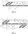
- the infrared reflective layer 14b can be adjacent to the SLML 16, as shown in FIGs. 1 and 3 .
- the infrared reflective layer 14b can be between a first SLML 16a, and a second SLML 16b, as shown in FIGs. 4 , 5 , 7 and 8 .
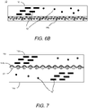
- the infrared reflective layer 14b can conform to a microstructured layer, as shown in FIG. 7 .
- the optical device 10 can include an infrared reflective layer 14b made of a metal, in which the optical device 10 is a directional or oriented reflector of infrared light.
- the infrared transparent particles can provide an appearance of color in the visible wavelength range while being transparent in the infrared wavelength range.
- the at least one infrared reflective material can be an infrared reflective layer 14c in a discontinuous form, as shown in FIGs. 6A and 6B .
- the discontinuous form can be the plurality of infrared reflective particles present on a surface of the first SLML 16 to form a layer 14c.
- the plurality of infrared reflective particles, on a surface of the first SLML 16a to form a layer 14c can have an average particle size D50 greater than 400 nm, for example, from about 401 nm to about 5000 nm, and as a further example, from about 450 nm to about 3500 nm.
- the optical device 10 can not diffuse reflection of the infrared light 20.
- the optical device 10 can include a first SLML 16 with a layer of a plurality of titanium dioxide particles on a surface of the first SLML 16, in which the optical device 10 is a diffuse reflector of infrared light.
- the plurality of infrared reflective particles formed in a layer 14c can be present in a carrier, as shown in FIG. 6B .
- the carrier can be a host material, as discussed herein relative to the SLML.
- the carrier can be a solvent.
- Non-limiting examples of a solvent can include acetates, such as ethyl acetate, propyl acetate, and butyl acetate; acetone; water; ketones, such as dimethyl ketone (DMK), methylethyl ketone (MEK), secbutyl methyl ketone (SBMK), ter-butyl methyl ketone (TBMK), cyclopenthanon, and anisole; glycol and glycol derivatives, such as propylene glycol methyl ether, and propylene glycol methyl ether acetate; alcohols, such as isopropyl alcohol, and diacetone alcohol; esters, such as malonates; heterocyclic solvents, such as n-methyl pyrrolidone; hydrocarbons, such as toluene, and xylene; coalescing solvents, such as glycol ethers; and mixtures thereof.
- DMK dimethyl ketone
- MEK methylethyl ketone
- the optical device 10 can be any and all combinations of an SLML 16 with infrared transparent particles 12 and at least one infrared reflective material 14 (a, b, c).
- FIG. 1 is an optical device 10 including an SLML 16 with infrared transparent particles (particles and/or platelets) 12 and infrared reflective particles (particles and/or platelets) dispersed therein; and an infrared reflective layer 14b adjacent to the SLML 16.
- FIG. 2 is an optical device 10 including an SLML 16 with infrared transparent particles (particles and/or platelets) 12 and infrared reflective particles (particles and/or platelets) dispersed therein.
- FIG. 1 is an optical device 10 including an SLML 16 with infrared transparent particles (particles and/or platelets) 12 and infrared reflective particles (particles and/or platelets) dispersed therein.
- FIG. 1 is an optical device 10 including an SLML 16 with infrared transparent
- FIG. 3 is an optical device 10 including an SLML 16 with infrared transparent particles (particles and/or platelets) 12 dispersed therein; and an infrared reflective layer 14b adjacent to the SLML 16.
- FIG. 4 is similar to FIG. 3 , but the infrared reflective layer 14b is between a first SLML 16a and a second SLML 16b.
- FIG. 5 is similar to FIG. 1 , but the infrared reflective layer 14b is between a first SLML 16a and a second SLML 16b.
- FIG. 6A and 6B illustrate an optical device 10 including a SLML 16 with infrared transparent particles (particles and/or platelets) 12 dispersed therein; and an infrared reflective material in the form of a plurality of particles forming a discontinuous layer 14c, optionally in a carrier, as shown in FIG. 6B .
- FIG. 7 illustrates another optical device 10 having a first SLML 16a comprising infrared transparent particles 12, a second SLML 16b comprising infrared transparent particles 12; and at least one reflective material 14b.
- the at least one infrared reflective material is an infrared reflective layer.
- the infrared reflective layer 14b is a single continuous piece of infrared reflective material located between the first SLML 16a and the second SLML 16b.
- the infrared reflective material can be present on a plurality of beads 22 or any other microstructured surface.
- the beads 22 or microstructured surface can enable the infrared reflective material 14b to provide diffuse reflection of infrared light.
- the beads 22 can be embedded in a carrier between the first SLML 16a and the second SLML 16b.
- FIG. 8 illustrates an optical device 10 including a first SLML 16a, a second SLML 16b, and an infrared reflector layer 14b between them.
- the infrared reflector layer 14b can have a physical thickness that is minimal, for example, having an optical density (OD) ranging from about 1 to about 2, so that the infrared reflector layer 14b can transmit the Radar K and W bands used for automotive short and long range radar sensors.
- the chosen thickness of the reflector layer allows sufficient transmission of Radar K and W bands while providing metallic appearance. Colored appearance of the device can be achieved by adding selective light modulating particles to layers 16a and 16b.
- a method of making an optical device comprising depositing, on a substrate, at least one infrared reflective material chosen from an infrared reflective layer and a plurality of infrared reflective particles; and depositing onto the at least one infrared reflective material a first selective light modulating layer including infrared transparent particles.
- the method also includes depositing, between the at least one infrared reflective material and the substrate, a second selective light modulating layer on an opposite surface of the at least one infrared reflective material from the first selective light modulating layer.
- the first selective light modulating layer can be patterned to form a non-planar surface.
- a method of making an optical device including depositing a carrier including a plurality of beads; drying the carrier including beads to form a microstructured layer; applying an infrared reflective layer to the dried microstructured layer; and depositing a first selective light modulating layer to the infrared reflective layer.
- the infrared reflective layer can conform to the microstructured layer.
- the step of depositing the first selective light modulating layer can include a liquid coating process.
- the method can further include, before the depositing of the carrier including beads, a step of depositing a second SLML layer.
- the selective light modulator layer can be as described above.
Landscapes
- Physics & Mathematics (AREA)
- General Physics & Mathematics (AREA)
- Optics & Photonics (AREA)
- Engineering & Computer Science (AREA)
- Health & Medical Sciences (AREA)
- Dispersion Chemistry (AREA)
- Chemical & Material Sciences (AREA)
- Manufacturing & Machinery (AREA)
- Toxicology (AREA)
- Nonlinear Science (AREA)
- Ophthalmology & Optometry (AREA)
- Mechanical Engineering (AREA)
- Optical Filters (AREA)
- Laminated Bodies (AREA)
- Optical Elements Other Than Lenses (AREA)
Applications Claiming Priority (1)
| Application Number | Priority Date | Filing Date | Title |
|---|---|---|---|
| US17/158,865 US12332464B2 (en) | 2021-01-26 | 2021-01-26 | Optical device with at least one infrared reflective material |
Publications (1)
| Publication Number | Publication Date |
|---|---|
| EP4033293A1 true EP4033293A1 (de) | 2022-07-27 |
Family
ID=80001607
Family Applications (1)
| Application Number | Title | Priority Date | Filing Date |
|---|---|---|---|
| EP22153049.6A Pending EP4033293A1 (de) | 2021-01-26 | 2022-01-24 | Optische vorrichtung mit mindestens einem infrarot-reflektierenden material |
Country Status (3)
| Country | Link |
|---|---|
| US (2) | US12332464B2 (de) |
| EP (1) | EP4033293A1 (de) |
| CN (1) | CN114791639A (de) |
Families Citing this family (1)
| Publication number | Priority date | Publication date | Assignee | Title |
|---|---|---|---|---|
| EP4095109A3 (de) * | 2021-03-19 | 2023-01-25 | Viavi Solutions Inc. | Artikel mit einer optischen oberfläche mit entwickelten funktionen |
Citations (7)
| Publication number | Priority date | Publication date | Assignee | Title |
|---|---|---|---|---|
| US6366397B1 (en) * | 2000-03-10 | 2002-04-02 | Ntt Advanced Technology Corporation | Infrared radiation reflector and infrared radiation transmitting composition |
| US20030030041A1 (en) * | 2000-08-15 | 2003-02-13 | Yasuhiro Genjima | Composition for forming infrared transmitting layer, infrared reflector, and processed article |
| US20040068046A1 (en) * | 2001-01-22 | 2004-04-08 | Gerd Hugo | Coating with a negligible solar absorption |
| US20100047620A1 (en) * | 2007-02-05 | 2010-02-25 | Ppg Industries Ohio, Inc. | Solar reflective coatings and coating systems |
| US20120107584A1 (en) * | 2010-11-02 | 2012-05-03 | Eibon William E | Solar Reflective Coatings Systems |
| US20150004424A1 (en) * | 2011-09-16 | 2015-01-01 | Basf Se | Coating system |
| US20190350399A1 (en) * | 2010-12-03 | 2019-11-21 | 3G Mermet Corporation | Near Infrared Reflecting Composition and Coverings for Architectural Openings Incorporating Same |
Family Cites Families (15)
| Publication number | Priority date | Publication date | Assignee | Title |
|---|---|---|---|---|
| US6939014B1 (en) | 2001-12-31 | 2005-09-06 | Jenmar Visual Systems, Inc. | Liquid transmissive filter having anisotropic properties and method of fabrication |
| JP3982466B2 (ja) * | 2002-09-25 | 2007-09-26 | 住友金属鉱山株式会社 | 熱線遮蔽成分分散体とその製造方法およびこの分散体を用いて得られる熱線遮蔽膜形成用塗布液と熱線遮蔽膜並びに熱線遮蔽樹脂成形体 |
| US20100025641A1 (en) * | 2008-08-04 | 2010-02-04 | Fujifilm Corporation | Infrared region selective reflection coat and infrared region selective reflection film |
| JP4888585B2 (ja) | 2010-06-16 | 2012-02-29 | ソニー株式会社 | 光学体、壁材、建具、および日射遮蔽装置 |
| US20130288027A1 (en) * | 2010-12-28 | 2013-10-31 | US Coatings IP Co. LLC | Multi-layer composite |
| CN102590906A (zh) | 2012-02-29 | 2012-07-18 | 北京化工大学 | 一种高分子基复合结构漫反射材料 |
| KR101836075B1 (ko) * | 2013-12-27 | 2018-03-08 | 가부시키가이샤 아이피 솔루션즈 | 정보 입력 보조 시트 |
| CN106461825B (zh) | 2014-05-09 | 2020-04-03 | 3M创新有限公司 | 彩色回射制品 |
| JP6400362B2 (ja) * | 2014-07-18 | 2018-10-03 | デクセリアルズ株式会社 | 光学部材 |
| JP6301242B2 (ja) * | 2014-11-28 | 2018-03-28 | 富士フイルム株式会社 | 赤外線反射パターン形成体 |
| WO2016117452A1 (ja) | 2015-01-19 | 2016-07-28 | 旭硝子株式会社 | 光学装置および光学部材 |
| JP6553708B2 (ja) * | 2015-03-12 | 2019-07-31 | 富士フイルム株式会社 | 重合性組成物、フィルム、および投映像表示用ハーフミラー |
| EP3263649B1 (de) | 2016-06-27 | 2025-04-30 | Viavi Solutions Inc. | Optische vorrichtungen |
| JPWO2018074527A1 (ja) | 2016-10-18 | 2019-08-08 | マクセルホールディングス株式会社 | 透明遮熱断熱部材 |
| US11865810B2 (en) * | 2019-05-08 | 2024-01-09 | Lifelabs Design, Inc. | Radiative-heating clothing fabric with colors |
-
2021
- 2021-01-26 US US17/158,865 patent/US12332464B2/en active Active
-
2022
- 2022-01-24 EP EP22153049.6A patent/EP4033293A1/de active Pending
- 2022-01-24 CN CN202210077873.7A patent/CN114791639A/zh active Pending
-
2025
- 2025-05-19 US US19/212,593 patent/US20250377491A1/en active Pending
Patent Citations (7)
| Publication number | Priority date | Publication date | Assignee | Title |
|---|---|---|---|---|
| US6366397B1 (en) * | 2000-03-10 | 2002-04-02 | Ntt Advanced Technology Corporation | Infrared radiation reflector and infrared radiation transmitting composition |
| US20030030041A1 (en) * | 2000-08-15 | 2003-02-13 | Yasuhiro Genjima | Composition for forming infrared transmitting layer, infrared reflector, and processed article |
| US20040068046A1 (en) * | 2001-01-22 | 2004-04-08 | Gerd Hugo | Coating with a negligible solar absorption |
| US20100047620A1 (en) * | 2007-02-05 | 2010-02-25 | Ppg Industries Ohio, Inc. | Solar reflective coatings and coating systems |
| US20120107584A1 (en) * | 2010-11-02 | 2012-05-03 | Eibon William E | Solar Reflective Coatings Systems |
| US20190350399A1 (en) * | 2010-12-03 | 2019-11-21 | 3G Mermet Corporation | Near Infrared Reflecting Composition and Coverings for Architectural Openings Incorporating Same |
| US20150004424A1 (en) * | 2011-09-16 | 2015-01-01 | Basf Se | Coating system |
Also Published As
| Publication number | Publication date |
|---|---|
| US20220236464A1 (en) | 2022-07-28 |
| US12332464B2 (en) | 2025-06-17 |
| CN114791639A (zh) | 2022-07-26 |
| US20250377491A1 (en) | 2025-12-11 |
Similar Documents
| Publication | Publication Date | Title |
|---|---|---|
| JP7798829B2 (ja) | 機能性分子を有する光学道具 | |
| US11754848B2 (en) | Optical devices with azimuthal modulator layer | |
| KR100609302B1 (ko) | 중합체의 다층 반사 코팅을 갖춘 재귀반사 물품 | |
| US20250377491A1 (en) | Optical device with at least one infrared reflective material | |
| US11118061B2 (en) | Article including at least one metal portion | |
| US12442971B2 (en) | Optical devices | |
| JP7166223B2 (ja) | 着色反射層を有する光学道具 | |
| US20120313075A1 (en) | Optical component, products including same, and methods for making same | |
| CN113050209A (zh) | 高色度薄片 | |
| WO2001094104A3 (en) | Method of forming antireflective coatings | |
| HK40069313A (en) | Optical device with at least one infrared reflective material | |
| US20240217141A1 (en) | Article including a release layer | |
| CN113711091A (zh) | 具有色彩调谐层的制品 | |
| HK40040569A (en) | Optical device | |
| HK40056567A (en) | Article with a color-tuning layer |
Legal Events
| Date | Code | Title | Description |
|---|---|---|---|
| PUAI | Public reference made under article 153(3) epc to a published international application that has entered the european phase |
Free format text: ORIGINAL CODE: 0009012 |
|
| STAA | Information on the status of an ep patent application or granted ep patent |
Free format text: STATUS: THE APPLICATION HAS BEEN PUBLISHED |
|
| AK | Designated contracting states |
Kind code of ref document: A1 Designated state(s): AL AT BE BG CH CY CZ DE DK EE ES FI FR GB GR HR HU IE IS IT LI LT LU LV MC MK MT NL NO PL PT RO RS SE SI SK SM TR |
|
| RAP3 | Party data changed (applicant data changed or rights of an application transferred) |
Owner name: VIAVI SOLUTIONS INC. |
|
| STAA | Information on the status of an ep patent application or granted ep patent |
Free format text: STATUS: REQUEST FOR EXAMINATION WAS MADE |
|
| 17P | Request for examination filed |
Effective date: 20230127 |
|
| RBV | Designated contracting states (corrected) |
Designated state(s): AL AT BE BG CH CY CZ DE DK EE ES FI FR GB GR HR HU IE IS IT LI LT LU LV MC MK MT NL NO PL PT RO RS SE SI SK SM TR |
|
| P01 | Opt-out of the competence of the unified patent court (upc) registered |
Effective date: 20230530 |
|
| STAA | Information on the status of an ep patent application or granted ep patent |
Free format text: STATUS: EXAMINATION IS IN PROGRESS |
|
| 17Q | First examination report despatched |
Effective date: 20240710 |