EP4033229B1 - Verfahren zur berechnung des verhältnisses der dielektrizität zum luftporengehalt von asphaltbeton mit einer einzigen kalibrierungsmessung - Google Patents
Verfahren zur berechnung des verhältnisses der dielektrizität zum luftporengehalt von asphaltbeton mit einer einzigen kalibrierungsmessung Download PDFInfo
- Publication number
- EP4033229B1 EP4033229B1 EP22151124.9A EP22151124A EP4033229B1 EP 4033229 B1 EP4033229 B1 EP 4033229B1 EP 22151124 A EP22151124 A EP 22151124A EP 4033229 B1 EP4033229 B1 EP 4033229B1
- Authority
- EP
- European Patent Office
- Prior art keywords
- dielectric
- asphalt
- mix
- calibration curve
- sample
- Prior art date
- Legal status (The legal status is an assumption and is not a legal conclusion. Google has not performed a legal analysis and makes no representation as to the accuracy of the status listed.)
- Active
Links
Images





Classifications
-
- G—PHYSICS
- G01—MEASURING; TESTING
- G01N—INVESTIGATING OR ANALYSING MATERIALS BY DETERMINING THEIR CHEMICAL OR PHYSICAL PROPERTIES
- G01N33/00—Investigating or analysing materials by specific methods not covered by groups G01N1/00 - G01N31/00
- G01N33/42—Road-making materials
-
- G—PHYSICS
- G01—MEASURING; TESTING
- G01R—MEASURING ELECTRIC VARIABLES; MEASURING MAGNETIC VARIABLES
- G01R27/00—Arrangements for measuring resistance, reactance, impedance, or electric characteristics derived therefrom
- G01R27/02—Measuring real or complex resistance, reactance, impedance, or other two-pole characteristics derived therefrom, e.g. time constant
- G01R27/26—Measuring inductance or capacitance; Measuring quality factor, e.g. by using the resonance method; Measuring loss factor; Measuring dielectric constants ; Measuring impedance or related variables
- G01R27/2617—Measuring dielectric properties, e.g. constants
-
- G—PHYSICS
- G01—MEASURING; TESTING
- G01N—INVESTIGATING OR ANALYSING MATERIALS BY DETERMINING THEIR CHEMICAL OR PHYSICAL PROPERTIES
- G01N27/00—Investigating or analysing materials by the use of electric, electrochemical, or magnetic means
- G01N27/02—Investigating or analysing materials by the use of electric, electrochemical, or magnetic means by investigating impedance
- G01N27/22—Investigating or analysing materials by the use of electric, electrochemical, or magnetic means by investigating impedance by investigating capacitance
- G01N27/221—Investigating or analysing materials by the use of electric, electrochemical, or magnetic means by investigating impedance by investigating capacitance by investigating the dielectric properties
-
- G—PHYSICS
- G01—MEASURING; TESTING
- G01N—INVESTIGATING OR ANALYSING MATERIALS BY DETERMINING THEIR CHEMICAL OR PHYSICAL PROPERTIES
- G01N33/00—Investigating or analysing materials by specific methods not covered by groups G01N1/00 - G01N31/00
- G01N33/38—Concrete; Lime; Mortar; Gypsum; Bricks; Ceramics; Glass
- G01N33/383—Concrete or cement
-
- G—PHYSICS
- G01—MEASURING; TESTING
- G01S—RADIO DIRECTION-FINDING; RADIO NAVIGATION; DETERMINING DISTANCE OR VELOCITY BY USE OF RADIO WAVES; LOCATING OR PRESENCE-DETECTING BY USE OF THE REFLECTION OR RERADIATION OF RADIO WAVES; ANALOGOUS ARRANGEMENTS USING OTHER WAVES
- G01S13/00—Systems using the reflection or reradiation of radio waves, e.g. radar systems; Analogous systems using reflection or reradiation of waves whose nature or wavelength is irrelevant or unspecified
- G01S13/88—Radar or analogous systems specially adapted for specific applications
- G01S13/885—Radar or analogous systems specially adapted for specific applications for ground probing
-
- G—PHYSICS
- G01—MEASURING; TESTING
- G01S—RADIO DIRECTION-FINDING; RADIO NAVIGATION; DETERMINING DISTANCE OR VELOCITY BY USE OF RADIO WAVES; LOCATING OR PRESENCE-DETECTING BY USE OF THE REFLECTION OR RERADIATION OF RADIO WAVES; ANALOGOUS ARRANGEMENTS USING OTHER WAVES
- G01S7/00—Details of systems according to groups G01S13/00, G01S15/00, G01S17/00
- G01S7/02—Details of systems according to groups G01S13/00, G01S15/00, G01S17/00 of systems according to group G01S13/00
- G01S7/40—Means for monitoring or calibrating
- G01S7/4052—Means for monitoring or calibrating by simulation of echoes
- G01S7/4082—Means for monitoring or calibrating by simulation of echoes using externally generated reference signals, e.g. via remote reflector or transponder
- G01S7/4086—Means for monitoring or calibrating by simulation of echoes using externally generated reference signals, e.g. via remote reflector or transponder in a calibrating environment, e.g. anechoic chamber
-
- G—PHYSICS
- G01—MEASURING; TESTING
- G01S—RADIO DIRECTION-FINDING; RADIO NAVIGATION; DETERMINING DISTANCE OR VELOCITY BY USE OF RADIO WAVES; LOCATING OR PRESENCE-DETECTING BY USE OF THE REFLECTION OR RERADIATION OF RADIO WAVES; ANALOGOUS ARRANGEMENTS USING OTHER WAVES
- G01S7/00—Details of systems according to groups G01S13/00, G01S15/00, G01S17/00
- G01S7/02—Details of systems according to groups G01S13/00, G01S15/00, G01S17/00 of systems according to group G01S13/00
- G01S7/41—Details of systems according to groups G01S13/00, G01S15/00, G01S17/00 of systems according to group G01S13/00 using analysis of echo signal for target characterisation; Target signature; Target cross-section
- G01S7/411—Identification of targets based on measurements of radar reflectivity
- G01S7/412—Identification of targets based on measurements of radar reflectivity based on a comparison between measured values and known or stored values
Definitions
- the disclosed technology relates generally to methods for computing compaction of asphalt concrete, and, more specifically, to a method to calculate an amount of compaction of asphalt concrete based only on a single calibration measurement.
- GPR Ground Penetrating Radar
- P Georgiou et al "Parametric optimization of Ground Penetrating Radar approach for assessing asphalt pavement surface layers compaction", Journal of Applied Geophysics, vol. 182, 104187 (2020 ).
- Knowledge of the effective dielectric of asphalt is useful in calculating the density of the asphalt, or, more accurately, its air void content. Once a calibration curve is created that maps dielectric to air void content, the density can be known simply by measuring the dielectric value at a location on the road.
- the relationship between dielectric and air void content is typically determined by obtaining several asphalt samples, usually about 6 inches in diameter and a 2-4 inches thick. By using a few such samples at different air void contents, either drilled from the road (Cores) or created in the lab (Pucks), and by measuring both the dielectric and the air void content of each sample, a curve that maps the two measurements to each other can be calculated.
- this prior art method is laborious, since calibration curves, requiring perhaps 10 cores, are required for hundreds of asphalt mix designs used for paving operations.
- a mix design selected for a paving project often needs to be adjusted, for example due to changes in the temperature or the ambient moisture (e.g. rain), requiring frequent curve calculations.
- Daily regeneration of calibration curves is burdensome, since a lab technician must create multiple asphalt samples and measure the densities and dielectrics of such samples each time conditions change.
- the disclosed technology relates generally to methods for computing compaction of asphalt concrete, and, more specifically, to a method to calculate densities that needs only a single calibration measurement to create a calibration curve.
- the method according to the invention is defined in claim 1.
- the disclosed technology has implications not only for saving time and money, but more importantly saving lives, since reducing the number of cores needed reduces the hazards associated with collecting them.
- Dielectric - an electromagnetic property that relates to the ability of a material to store energy in the presence of an electric field.
- Effective Dielectric an average dielectric of a micro-inhomogeneous medium, i.e. a medium whose dielectric is not homogeneous on a small scale.
- Asphalt - a composite material comprising and having, typically, at least 90% aggregate (i.e. rock fragments) and bitumen, and, in some cases, also including additional materials. Also known as “Pavement” in North America and as “asphalt concrete” in technical papers, these terms are used interchangeably.
- Dielectric Mixing Equation - an equation that calculates the effective dielectric of a dielectrically inhomogeneous medium, given volume percentages and dielectrics of constituents in the medium.
- Asphalt Air Void Content The percentage or volume ratio of air in an asphalt sample.
- Bitumen - a black viscous mixture of hydrocarbons obtained naturally or as a residue from petroleum distillation. Bitumen is commonly used as a constituent in asphalt concrete. It may also be called tar or binder.
- Aggregate - rock and sand constituents typically included in asphalt concrete may be taken from nearby quarries, and as such have highly regional material properties (shape, density, dielectric, porosity etc.).
- Air Void Air trapped inside asphalt concrete.
- the air void is typically expressed as a percentage of the total volume of asphalt concrete.
- Magnetic Permeability an electromagnetic property that relates the magnetic induction inside a material to the magnetic field intensity.
- Mix Design a particular combination of aggregate, bitumen and possibly other constituents that are mixed together to make asphalt. Different mix designs are customized for the locations where the asphalt is to be used.
- a novel method for generating a calibration curve of asphalt concrete of a known mix design by measuring only one physical sample involves obtaining a single sample of the known asphalt concrete mix and air void content, and obtaining a dielectric measurement of the single sample.
- An "ideal dielectric" at a theoretical 0% air void content is then computed using only that sample's measured dielectric value and void content.
- a dielectric vs. percent compaction calibration curve can then be uniquely determined based only on one measured point and the calculated ideal dielectric value.
- a method for identifying a characteristic of a known asphalt mix is provided.
- a calibration curve for the known asphalt mix is obtained using the method of the disclosed technology described above.
- a second sample of the asphalt mix is obtained, the second sample having an unknown void percentage, and a second dielectric of the second sample is measured.
- the second dielectric is compared to the calibration curve, such that when the second dielectric is on the calibration curve, a second air void percentage of the second sample is extracted from the calibration curve.
- this method can be used to identify the need to decompose and analyze the second sample to understand what changed in the asphalt mix or in the environment surrounding the asphalt mix.
- the method can be used to identify some change in the asphalt mix or in the environment, and to help adjust the asphalt mix to match the calibration curve.
- the method further includes, in response to identifying some change in the asphalt mix or in the environment, computing an updated calibration curve for the changed asphalt mix or at the changed conditions.
- the method further includes comparing the extracted second air void percentage to an expected air void percentage, and when the extracted second air void percentage is distinct from the expected air void percentage, decomposing and analyzing the second sample to identify a change in the asphalt mix or in an environment surrounding the asphalt mix.
- a method for calculating a dielectric of an aggregate forming part of an asphalt concrete sample including the aggregate and at least one non-aggregate constituent includes solving the equation of the disclosed technology discussed hereinabove using the ideal dielectric of the asphalt, a known volume percent of the non-aggregate constituents in the asphalt concrete sample, and a dielectric of the non-aggregate constituents.
- a method for identifying a characteristic of a known asphalt mix includes using a dielectric measurement of a single calibration puck or core of the known asphalt concrete mix and generating a dielectric vs. percent compaction calibration curve for the known asphalt mix.
- a second sample, which would be a puck or core, of the asphalt mix is obtained and a second dielectric of the second sample is measured.
- the second sample has an unknown void percentage.
- the second sample's dielectric is compared to the calibration curve, and when the second sample's dielectric is on the calibration curve, an air void percentage of the second sample is extracted from the calibration curve.
- the second sample's dielectric is not on the calibration curve
- the second sample is decomposed and analyzed to identify a change to the known asphalt mix, and based on the measured dielectric of the second sample, and the identified change to the known asphalt mix, a revised dielectric vs. percent compaction calibration curve can be generated for the asphalt mix following the change.
- the generating of the calibration curve for the known asphalt mix includes obtaining the single calibration puck or core of the known asphalt concrete mix, the single calibration puck or core having a known void percentage, and obtaining a dielectric measurement of the single calibration puck or core. Using only the dielectric measurement of the single calibration puck or core, components of the known mix, and a dielectric of air, computing an ideal dielectric for the asphalt concrete mix at 0% voids, and generating a dielectric vs. percent compaction calibration curve based only on the dielectric measurement of the single calibration puck or core and on the computed ideal dielectric.
- a method of projecting an expected dielectric of a known asphalt mix at a specific void percentage includes using a dielectric measurement of a single calibration puck or core of the known asphalt concrete mix, generating a dielectric vs. percent compaction calibration curve for the known asphalt mix, and extracting from the calibration curve for the known asphalt mix the expected dielectric for the known asphalt mix at the specific void percentage.
- the invention provides a method for generating a dielectric to air void curve, or calibration curve, for identifying an amount of compaction of asphalt concrete of a known mix, using a single calibration measurement, according to claim 1.
- the method of the disclosed technology is based on a modified form of equations, originally derived to solve a different problem related to the magnetic permeability limits of a mixture of two constituent materials possessing different magnetic permeabilities.
- the combined magnetic permeability of a mixture can vary depending on how the two constituents are randomly clustered together in the mixture. Certain areas of the mixture may comprise a slightly higher concentration of one constituent, compared to others.
- the measured magnetic permeability of the mixture thus varies, to some degree, depending on the variations in random clustering.
- the Hashin-Shtrikman (HS) equations describe the maximum and minimum magnetic permeability of the mix for each mixing ratio. For example, if two different sands possessing different magnetic permeabilities were to be combined 100 different times in a bucket at even ratios, and mixed with a shovel, the measured magnetic permeability would be within minimum and maximum values calculated using the HS equations.
- the HS equations have been modified (M-HS equations) to compute the maximum and minimum dielectric values for mixtures comprising or containing constituents having different dielectrics.
- M-HS equations modified
- the inventor has found that the average of the minimum and maximum dielectric values obtained from the M-HS equations describes the relationship of different effective dielectric values and associated air void contents in asphalt exceedingly well, provided that an accurate effective dielectric of the asphalt at "zero percent void content" is substantially known or is known within an acceptable tolerance level.
- Gmm Theoretical Maximum Specific Gravity
- the M-HS is given by: Where:
- Figure 1 illustrates a plot of dielectric mixing curves using the average H-S bounds. As seen in Figure 1 , for each dielectric and associated void percent, there is a specific Gmm dielectric. The inventor has discovered that the obtained curves, shown in Figure 1 , are substantially linear, particularly for low dielectrics. This allows the effective dielectric at 0% void, or at Gmm, to be extrapolated or extracted, for example by extending the relatively linear curve or by solving the equation for ⁇ e .
- the Gmm dielectric can be calculated directly by inserting the known void fraction (f) and associated dielectric ( ⁇ ) of a puck in the modified-HS equation and solving for ⁇ e .
- the calibration curve may be found using a single asphalt puck, enabling easier and more attainable adjustments for daily changes in the asphalt mix or in the ambient conditions.
- Figure 2 is a flow chart of an embodiment of a method for generating a calibration curve of asphalt concrete of a known mix, using a single calibration measurement, according to embodiments of the disclosed technology.
- a known asphalt mix design is obtained, with known proportions of known constituent materials.
- a portion of the asphalt mix is then compacted to generate a puck of known compaction percentage at step 12.
- a dielectric measurement of the asphalt mix with the known compaction percentage is obtained at step 14 from the puck of step 12.
- the first dielectric measurement, extracted at step 14, is a control or baseline measurement for the asphalt mix.
- the ideal dielectric for the asphalt mix at 100% compaction, or the Gmm dielectric for the asphalt mix is determined, by solving the M-HS equations discussed hereinabove to obtain a value of the Gmm dielectric.
- a dielectric vs. compaction percentage curve for the asphalt mix is generated, or determined, at step 18, based on the measured dielectric for the obtained puck and the computed Gmm dielectric for the asphalt mix.
- the curve generated in step 18 may function as a calibration curve, for identifying the compaction level of any puck or sample of the asphalt mix.
- Figure 3 is a flow chart of an embodiment of a method for using a calibration curve, such as the one generated using the method of Figure 2 , for identifying a characteristic of an asphalt mix, according to embodiments of the disclosed technology.
- a calibration curve such as the one generated using the method of Figure 2 .
- a second puck of the known asphalt mix having an unknown compaction percentage, is obtained.
- the second puck may be obtained by compacting asphalt obtained from a truck delivering asphalt to a paving job location.
- a second dielectric value corresponding to the second puck is measured at step 32.
- the second measured dielectric is compared to the calibration curve.
- the dielectric may be off of the expected curve if there has been an unknown change to the mix design (e.g. more bitumen was added to the mix on a very cold day to make it more workable), if there has been a change to the moisture level in the mix (e.g. if the mix had been rained upon), or if there has been a change to the aggregate - to the sand or rock mineral content in the mix.
- the second puck may be decomposed and analyzed, in order to determine what has changed about the asphalt mix or about the environment.
- the asphalt mix is modified to compensate for changes identified during the analysis of step 36, so that the modified asphalt mix once again suits the computed curve.
- a new calibration curve is computed for the asphalt mix, following the change identified at step 36, for example using the method of Figure 2 . The new calibration curve may then be used for all required computations using the asphalt mix following the change it had undergone.
- the percentage of air voids in the second puck may be extracted from the curve at step 42.
- the extracted percentage of air voids in the second puck is compared to an anticipated (theoretical) air void percentage value, at step 44. If the extracted percentage of air voids in the second puck matches the anticipated air void percentage, the method terminates, as the air void percentage of the second puck is known. Otherwise, if extracted percentage of air voids in the second puck does not match the anticipated air void percentage value, the flow may proceed to step 36, for analysis of the second puck in order to understand why the mismatch has occurred.
- the M-HS equations described hereinabove may further be used to calculate the dielectric of one main component of an asphalt sample, assuming the dielectric and volume percentage of the other main component are known.
- the dielectric of the aggregate if the dielectric and volume percentage of the bitumen are known. This yields key information to pavement engineers because anomalous aggregate dielectrics alert the operator to changes in the aggregate composition and/or in the moisture content. For example, if the dielectric of the aggregate when it is dry is known, an excessively high calculated aggregate dielectric from an asphalt sample infers the presence of moisture in the aggregate.
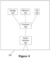
- FIG. 4 shows a high-level block diagram of a device that may be used to carry out the disclosed technology.
- Device 100 comprises a processor 105 that controls the overall operation of the computer by executing the device's program instructions which define such operation.
- the device's program instructions may be stored in a storage device 102 (e.g., magnetic disk, database) and loaded into memory 103, when execution of the console's program instructions is desired.
- the device's operation will be defined by the device's program instructions stored in memory 103 and/or storage 102, and the console will be controlled by processor 105 executing the console's program instructions.
- a device 100 also includes one, or a plurality of, input network interfaces for communicating with other devices via a network (e.g., the Internet).
- a network e.g., the Internet
- the device 100 further includes an electrical input interface.
- a device 100 also includes one or more output network interfaces 101 for communicating with other devices.
- Device 100 also includes input/output 104, representing devices which allow for user interaction with a computer (e.g., display, keyboard, mouse, speakers, buttons, etc.).
- a computer e.g., display, keyboard, mouse, speakers, buttons, etc.
- Figure 4 is a high-level representation of some of the components of such a device, for illustrative purposes. It should also be understood by one skilled in the art that the method and devices depicted in Figures 1 through 3 may be implemented on a device such as is shown in Figure 4 .
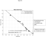
- a dataset of 12 pucks obtained from Maine was used to generate a first calibration curve, shown in Figure 5A .
- the calibration curve of Figure 5A which was generated using a least-squares fit line in accordance with prior art methods, plots the measured dielectric vs. the known void percentage for each puck in the dataset, and a linear approximation of the locations of the pucks is assumed to be the calibration curve.
- the linear approximation was then extended, as indicated by a dashed line in Figure 5A , to extrapolate the corresponding dielectric value for a mix having 0% voids, or the Gmm, which was equal to 5.10.
- the dielectric at Gmm was computed using the method of the disclosed technology, as described herein with respect to Figure 2 .
- Figure 5B plots the the dielectric at Gmm vs. measured % voids, as computed based on each of the pucks.
- the median Gmm value for all the pucks, indicated by a horizontal line in the graph of Figure 5B is at a dielectric value of 5.13 - within 0.03 of the value obtained in Figure 5A using a least-squares fit curve for the dielectrics and void percentage of each puck.
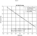
- a dataset of pucks obtained in NY in 2020 was used to generate two calibration curves, shown in Figure 6 .
- the first calibration curve of Figure 6 is indicated by a solid line and was generated using a least-squares fit line in accordance with prior art methods, plots the measured dielectric vs. the known void percentage for each puck in the dataset, and a linear approximation of the locations of the puck measurements is assumed to be the calibration curve.
- a second calibration curve for the mix was generated using only the measured dielectric and known %voids of the of the puck having 6% voids, based on the mixing model described hereinabove, and specifically based on the M-HS equations.
- the curve computed using prior art methods, based on measurement of multiple pucks, and the curve computed using the method of the present invention are very similar to each other.
- a dataset of pucks obtained from Utah in 2019 was used to generate two calibration curves, shown in Figure 7 .
- the first calibration curve of Figure 7 is indicated by a solid line and was generated using a least-squares fit line in accordance with prior art methods, plots the measured dielectric vs. the known void percentage for each puck in the dataset, and a linear approximation of the locations of the puck measurements is assumed to be the calibration curve.
- a second calibration curve for the mix was generated using only the measured dielectric and known %voids of the of the puck having 2.5% voids, based on the mixing model described hereinabove, and specifically based on the M-HS equations.
- the curve computed using prior art methods, based on measurement of multiple pucks, and the curve computed using the method of the present invention are very similar to each other, particularly for lower void percentages.
- a dataset of pucks obtained in 2018 from New York was used to generate two calibration curves, shown in Figure 8 .
- the first calibration curve was generated using a least-squares fit line in accordance with prior art methods, plots the measured dielectric vs. the known void percentage for each puck in the dataset, and a linear approximation of the locations of the puck measurements is assumed to be the calibration curve.
- a second calibration curve for the mix was generated using only the measured dielectric and known % voids of the puck having 5% voids, based on the mixing model described hereinabove, and specifically based on the M-HS equations.
- the curve computed using prior art methods, based on measurement of multiple pucks, and the curve computed using the method of the present invention are very similar to each other.
- a dataset of pucks obtained in 2018 from Minnesota was used to generate two calibration curves, shown in Figure 9 .
- the first calibration curve of Figure 9 was generated using a least-squares fit line in accordance with prior art methods, plots the measured dielectric vs. the known void percentage for each puck in the dataset, and a linear approximation of the locations of the puck measurements is assumed to be the calibration curve.
- the five datasets of pucks discussed hereinabove with respect to Examples 1-5 were compared to each other.
- the expected dielectric for a puck having 8% void (or 92% compaction) was extracted from the graph generated using the near fit squares of the prior art, and from the graph generated using the mixing model and the method of the disclose technology.
- the 92% compaction value is of particularly important because paving contractor bonuses and/or penalties often depend on the percentage of asphalt compacted above and/or below this threshold level.
- the term “substantially” is defined as “at least 95% of” the term which it modifies.
Landscapes
- Engineering & Computer Science (AREA)
- Physics & Mathematics (AREA)
- General Physics & Mathematics (AREA)
- Chemical & Material Sciences (AREA)
- Remote Sensing (AREA)
- Health & Medical Sciences (AREA)
- Life Sciences & Earth Sciences (AREA)
- Radar, Positioning & Navigation (AREA)
- General Health & Medical Sciences (AREA)
- Biochemistry (AREA)
- Analytical Chemistry (AREA)
- Immunology (AREA)
- Pathology (AREA)
- Computer Networks & Wireless Communication (AREA)
- Medicinal Chemistry (AREA)
- Food Science & Technology (AREA)
- Electromagnetism (AREA)
- Ceramic Engineering (AREA)
- Chemical Kinetics & Catalysis (AREA)
- Electrochemistry (AREA)
- Investigating Or Analyzing Materials By The Use Of Electric Means (AREA)
Claims (8)
- Verfahren zum Erstellen einer Kalibrierungskurve für Asphaltbeton einer bekannten Mischung, wobei das Verfahren Folgendes umfasst:Erhalten einer einzigen Probe der Asphaltbetonmischung, wobei die einzige Probe einen bekannten Prozentsatz an Poren aufweist;Erhalten einer Messung der Dielektrizität der einzigen Probe;Berechnen einer idealen Dielektrizität für die Asphaltbetonmischung mit 0 % Poren unter Verwendung nur der Messung der Dielektrizität der einzigen Probe, basierend auf der Gleichung
 ε die Messung der Dielektrizität der einzigen Probe ist;εe die ideale Dielektrizität der Asphaltmischung mit 0 % Poren ist;εi die Dielektrizität von Luft ist; undf ein Volumenanteil der Luft in der einzigen Probe ist; undErstellen einer Kalibrierungskurve für Dielektrizität vs. Prozentsatz an Poren, die nur auf der Messung der Dielektrizität der einzigen Probe und der Gleichung zum Berechnen der idealen Dielektrizität basiert.
 - Verfahren zum Identifizieren einer Eigenschaft einer bekannten Asphaltmischung, wobei das Verfahren Folgendes umfasst:Verwenden des Verfahrens nach Anspruch 1, um eine Kalibrierungskurve für die bekannte Asphaltmischung zu erhalten;Erhalten einer zweiten Probe der Asphaltmischung, wobei die zweite Probe einen unbekannten Prozentsatz an Poren aufweist;Messen einer zweiten Dielektrizität der zweiten Probe;Vergleichen der zweiten Dielektrizität mit der Kalibrierungskurve; undwenn die zweite Dielektrizität auf der Kalibrierungskurve liegt, Extrahieren eines zweiten Prozentsatzes an Luftporen der zweiten Probe aus der Kalibrierungskurve.
- Verfahren nach Anspruch 2, wobei das Verfahren, wenn die zweite Dielektrizität außerhalb der Kalibrierungskurve liegt, ferner Folgendes umfasst:
Zerlegen und Analysieren der zweiten Probe, um eine Änderung in der Asphaltmischung oder in einer die Asphaltmischung umgebenden Umgebung zu identifizieren. - Verfahren nach Anspruch 3, ferner umfassend als Reaktion auf das Identifizieren der Änderung in der Asphaltmischung oder in der Umgebung Modifizieren der Asphaltmischung, um sie an die Kalibrierungskurve anzupassen.
- Verfahren nach Anspruch 3, ferner umfassend als Reaktion auf das Identifizieren der Änderung in der Asphaltmischung oder in der Umgebung Berechnen einer aktualisierten Kalibrierungskurve für die geänderte Asphaltmischung oder unter den geänderten Bedingungen.
- Verfahren nach Anspruch 2, ferner umfassend:Vergleichen des extrahierten zweiten Prozentsatzes an Luftporen mit einem erwarteten Prozentsatz an Luftporen; undwenn der extrahierte zweite Prozentsatz an Luftporen sich von dem erwarteten Prozentsatz an Luftporen unterscheidet, Zerlegen und Analysieren der zweiten Probe, um eine Änderung in der Asphaltmischung oder in einer die Asphaltmischung umgebenden Umgebung festzustellen.
- Verfahren nach Anspruch 1, wobei die Asphaltprobe eine Scheibe oder ein aus einem Asphaltbelag entnommener Kern ist.
- Verfahren nach Anspruch 1, wobei die ideale Dielektrizität einer Mischung aus dem Durchschnitt oder Median von idealen Dielektrizitäten erstellt wird, die einzeln aus zwei oder mehreren Asphaltproben berechnet werden.
Applications Claiming Priority (2)
| Application Number | Priority Date | Filing Date | Title |
|---|---|---|---|
| US202163140292P | 2021-01-22 | 2021-01-22 | |
| US17/209,338 US11513146B2 (en) | 2021-01-22 | 2021-03-23 | Method for calculating dielectric versus air void content relationship for asphalt concrete using a single calibration measurement |
Publications (3)
| Publication Number | Publication Date |
|---|---|
| EP4033229A1 EP4033229A1 (de) | 2022-07-27 |
| EP4033229B1 true EP4033229B1 (de) | 2024-09-04 |
| EP4033229C0 EP4033229C0 (de) | 2024-09-04 |
Family
ID=79316717
Family Applications (1)
| Application Number | Title | Priority Date | Filing Date |
|---|---|---|---|
| EP22151124.9A Active EP4033229B1 (de) | 2021-01-22 | 2022-01-12 | Verfahren zur berechnung des verhältnisses der dielektrizität zum luftporengehalt von asphaltbeton mit einer einzigen kalibrierungsmessung |
Country Status (2)
| Country | Link |
|---|---|
| US (2) | US11513146B2 (de) |
| EP (1) | EP4033229B1 (de) |
Family Cites Families (1)
| Publication number | Priority date | Publication date | Assignee | Title |
|---|---|---|---|---|
| US7239150B2 (en) * | 2003-10-24 | 2007-07-03 | Troxler Electronic Laboratories, Inc. | Pavement material microwave density measurement methods and apparatuses |
-
2021
- 2021-03-23 US US17/209,338 patent/US11513146B2/en active Active
-
2022
- 2022-01-12 EP EP22151124.9A patent/EP4033229B1/de active Active
- 2022-11-21 US US17/990,860 patent/US11835558B1/en active Active
Also Published As
| Publication number | Publication date |
|---|---|
| US20220236309A1 (en) | 2022-07-28 |
| EP4033229C0 (de) | 2024-09-04 |
| US11513146B2 (en) | 2022-11-29 |
| EP4033229A1 (de) | 2022-07-27 |
| US11835558B1 (en) | 2023-12-05 |
Similar Documents
| Publication | Publication Date | Title |
|---|---|---|
| Nazarian et al. | Modulus-based construction specification for compaction of earthwork and unbound aggregate | |
| Uzan | Permanent deformation in flexible pavements | |
| Akbarimehr et al. | Correlations between compression index and index properties of undisturbed and disturbed Tehran clay | |
| Hassan et al. | Correlation of maximum laboratory dry density and optimum moisture content of soil with soil parameters | |
| Ansari et al. | A piezocone dissipation test interpretation method for hydraulic conductivity of soft clays | |
| Fondjo et al. | Assessment of the mineral composition of heaving soils using geotechnical properties | |
| Teng et al. | A novel criterion for assessing frost heave susceptibility of soils | |
| Look | An earthworks quality assurance methodology which avoids unreliable correlations | |
| Haupt et al. | Prediction of California Bearing Ratio and compaction characteristics of Transvaal soils from indicator properties | |
| Mousa et al. | Models for estimating optimum asphalt content from aggregate gradation | |
| Braham et al. | Characterizing Compactability of High RAP and Warm Mix Asphalt Mixtures in the Superpave Gyratory Compactor. | |
| Janeček et al. | Experimental study of compact sandstone deformation under axisymmetric triaxial loading along specific paths in stress space | |
| EP4033229B1 (de) | Verfahren zur berechnung des verhältnisses der dielektrizität zum luftporengehalt von asphaltbeton mit einer einzigen kalibrierungsmessung | |
| Rahimi et al. | Evaluation of the needle penetration test to estimate the uniaxial compressive strength of gypsum rocks | |
| Frid et al. | Moisture effect on asphalt dielectric permittivity: Simulating, sensitivity analysis and experimental validation | |
| Baziar et al. | Prediction of Excess Pore Water Pressure Generation in Sand–Silt Mixtures During Cyclic Loading: A Dissipated Energy-Based Model | |
| Truty | Estimating Hardening Soil-Brick model parameters for sands based on CPTU tests and laboratory experimental evidence | |
| O’Kelly et al. | Discussion: A comparative study on the application of artificial intelligence networks versus regression analysis for the prediction of clay plasticity [Arab J Geosci (2021) 14 (7), 534] | |
| US12618883B2 (en) | Methods for calculating a relative change in percent voids using electromagnetic wave reflection coefficients | |
| US20230194588A1 (en) | Methods for Calculating a Relative Change in Percent Voids using Electromagnetic Wave Reflection Coefficients | |
| Kuttah | Correlations between laboratory dynamic CBR and compaction parameters of unbound coarse aggregate for base courses | |
| Yaghoubi et al. | Hydro-mechanical behavior of unsaturated unbound pavement materials under repeated and static loading | |
| Ongen et al. | The effect of initial water content on the swelling pressure of soils | |
| da Silva et al. | Dynamic cone penetration utilization in estimating the resilient modulus of sandy soils | |
| Plati et al. | Impact of Moisture Content on Resilient Modulus Predictions for Unbound Granular Materials Using Stress-Dependent Constitutive Models |
Legal Events
| Date | Code | Title | Description |
|---|---|---|---|
| PUAI | Public reference made under article 153(3) epc to a published international application that has entered the european phase |
Free format text: ORIGINAL CODE: 0009012 |
|
| STAA | Information on the status of an ep patent application or granted ep patent |
Free format text: STATUS: THE APPLICATION HAS BEEN PUBLISHED |
|
| AK | Designated contracting states |
Kind code of ref document: A1 Designated state(s): AL AT BE BG CH CY CZ DE DK EE ES FI FR GB GR HR HU IE IS IT LI LT LU LV MC MK MT NL NO PL PT RO RS SE SI SK SM TR |
|
| STAA | Information on the status of an ep patent application or granted ep patent |
Free format text: STATUS: REQUEST FOR EXAMINATION WAS MADE |
|
| 17P | Request for examination filed |
Effective date: 20220926 |
|
| RBV | Designated contracting states (corrected) |
Designated state(s): AL AT BE BG CH CY CZ DE DK EE ES FI FR GB GR HR HU IE IS IT LI LT LU LV MC MK MT NL NO PL PT RO RS SE SI SK SM TR |
|
| REG | Reference to a national code |
Ref legal event code: R079 Ipc: G01N0027220000 Ref country code: DE Ref legal event code: R079 Ref document number: 602022005745 Country of ref document: DE Free format text: PREVIOUS MAIN CLASS: G01N0022000000 Ipc: G01N0027220000 |
|
| RIC1 | Information provided on ipc code assigned before grant |
Ipc: G01S 13/88 20060101ALI20240501BHEP Ipc: G01S 7/41 20060101ALI20240501BHEP Ipc: G01S 7/40 20060101ALI20240501BHEP Ipc: G01N 33/42 20060101ALI20240501BHEP Ipc: G01N 27/22 20060101AFI20240501BHEP |
|
| GRAP | Despatch of communication of intention to grant a patent |
Free format text: ORIGINAL CODE: EPIDOSNIGR1 |
|
| STAA | Information on the status of an ep patent application or granted ep patent |
Free format text: STATUS: GRANT OF PATENT IS INTENDED |
|
| INTG | Intention to grant announced |
Effective date: 20240613 |
|
| RIN1 | Information on inventor provided before grant (corrected) |
Inventor name: ROBERTS, ROGER |
|
| GRAS | Grant fee paid |
Free format text: ORIGINAL CODE: EPIDOSNIGR3 |
|
| GRAA | (expected) grant |
Free format text: ORIGINAL CODE: 0009210 |
|
| STAA | Information on the status of an ep patent application or granted ep patent |
Free format text: STATUS: THE PATENT HAS BEEN GRANTED |
|
| AK | Designated contracting states |
Kind code of ref document: B1 Designated state(s): AL AT BE BG CH CY CZ DE DK EE ES FI FR GB GR HR HU IE IS IT LI LT LU LV MC MK MT NL NO PL PT RO RS SE SI SK SM TR |
|
| REG | Reference to a national code |
Ref country code: GB Ref legal event code: FG4D |
|
| REG | Reference to a national code |
Ref country code: CH Ref legal event code: EP |
|
| REG | Reference to a national code |
Ref country code: IE Ref legal event code: FG4D |
|
| REG | Reference to a national code |
Ref country code: DE Ref legal event code: R096 Ref document number: 602022005745 Country of ref document: DE |
|
| U01 | Request for unitary effect filed |
Effective date: 20240930 |
|
| U07 | Unitary effect registered |
Designated state(s): AT BE BG DE DK EE FI FR IT LT LU LV MT NL PT RO SE SI Effective date: 20241024 |
|
| PG25 | Lapsed in a contracting state [announced via postgrant information from national office to epo] |
Ref country code: NO Free format text: LAPSE BECAUSE OF FAILURE TO SUBMIT A TRANSLATION OF THE DESCRIPTION OR TO PAY THE FEE WITHIN THE PRESCRIBED TIME-LIMIT Effective date: 20241204 |
|
| PG25 | Lapsed in a contracting state [announced via postgrant information from national office to epo] |
Ref country code: GR Free format text: LAPSE BECAUSE OF FAILURE TO SUBMIT A TRANSLATION OF THE DESCRIPTION OR TO PAY THE FEE WITHIN THE PRESCRIBED TIME-LIMIT Effective date: 20241205 Ref country code: PL Free format text: LAPSE BECAUSE OF FAILURE TO SUBMIT A TRANSLATION OF THE DESCRIPTION OR TO PAY THE FEE WITHIN THE PRESCRIBED TIME-LIMIT Effective date: 20240904 |
|
| U20 | Renewal fee for the european patent with unitary effect paid |
Year of fee payment: 4 Effective date: 20241213 |
|
| PG25 | Lapsed in a contracting state [announced via postgrant information from national office to epo] |
Ref country code: HR Free format text: LAPSE BECAUSE OF FAILURE TO SUBMIT A TRANSLATION OF THE DESCRIPTION OR TO PAY THE FEE WITHIN THE PRESCRIBED TIME-LIMIT Effective date: 20240904 |
|
| PG25 | Lapsed in a contracting state [announced via postgrant information from national office to epo] |
Ref country code: RS Free format text: LAPSE BECAUSE OF FAILURE TO SUBMIT A TRANSLATION OF THE DESCRIPTION OR TO PAY THE FEE WITHIN THE PRESCRIBED TIME-LIMIT Effective date: 20241204 Ref country code: ES Free format text: LAPSE BECAUSE OF FAILURE TO SUBMIT A TRANSLATION OF THE DESCRIPTION OR TO PAY THE FEE WITHIN THE PRESCRIBED TIME-LIMIT Effective date: 20240904 |
|
| PG25 | Lapsed in a contracting state [announced via postgrant information from national office to epo] |
Ref country code: RS Free format text: LAPSE BECAUSE OF FAILURE TO SUBMIT A TRANSLATION OF THE DESCRIPTION OR TO PAY THE FEE WITHIN THE PRESCRIBED TIME-LIMIT Effective date: 20241204 Ref country code: PL Free format text: LAPSE BECAUSE OF FAILURE TO SUBMIT A TRANSLATION OF THE DESCRIPTION OR TO PAY THE FEE WITHIN THE PRESCRIBED TIME-LIMIT Effective date: 20240904 Ref country code: NO Free format text: LAPSE BECAUSE OF FAILURE TO SUBMIT A TRANSLATION OF THE DESCRIPTION OR TO PAY THE FEE WITHIN THE PRESCRIBED TIME-LIMIT Effective date: 20241204 Ref country code: HR Free format text: LAPSE BECAUSE OF FAILURE TO SUBMIT A TRANSLATION OF THE DESCRIPTION OR TO PAY THE FEE WITHIN THE PRESCRIBED TIME-LIMIT Effective date: 20240904 Ref country code: GR Free format text: LAPSE BECAUSE OF FAILURE TO SUBMIT A TRANSLATION OF THE DESCRIPTION OR TO PAY THE FEE WITHIN THE PRESCRIBED TIME-LIMIT Effective date: 20241205 Ref country code: ES Free format text: LAPSE BECAUSE OF FAILURE TO SUBMIT A TRANSLATION OF THE DESCRIPTION OR TO PAY THE FEE WITHIN THE PRESCRIBED TIME-LIMIT Effective date: 20240904 |
|
| PG25 | Lapsed in a contracting state [announced via postgrant information from national office to epo] |
Ref country code: IS Free format text: LAPSE BECAUSE OF FAILURE TO SUBMIT A TRANSLATION OF THE DESCRIPTION OR TO PAY THE FEE WITHIN THE PRESCRIBED TIME-LIMIT Effective date: 20250104 |
|
| PG25 | Lapsed in a contracting state [announced via postgrant information from national office to epo] |
Ref country code: SM Free format text: LAPSE BECAUSE OF FAILURE TO SUBMIT A TRANSLATION OF THE DESCRIPTION OR TO PAY THE FEE WITHIN THE PRESCRIBED TIME-LIMIT Effective date: 20240904 |
|
| PG25 | Lapsed in a contracting state [announced via postgrant information from national office to epo] |
Ref country code: CZ Free format text: LAPSE BECAUSE OF FAILURE TO SUBMIT A TRANSLATION OF THE DESCRIPTION OR TO PAY THE FEE WITHIN THE PRESCRIBED TIME-LIMIT Effective date: 20240904 |
|
| PG25 | Lapsed in a contracting state [announced via postgrant information from national office to epo] |
Ref country code: SK Free format text: LAPSE BECAUSE OF FAILURE TO SUBMIT A TRANSLATION OF THE DESCRIPTION OR TO PAY THE FEE WITHIN THE PRESCRIBED TIME-LIMIT Effective date: 20240904 |
|
| PLBE | No opposition filed within time limit |
Free format text: ORIGINAL CODE: 0009261 |
|
| STAA | Information on the status of an ep patent application or granted ep patent |
Free format text: STATUS: NO OPPOSITION FILED WITHIN TIME LIMIT |
|
| 26N | No opposition filed |
Effective date: 20250605 |
|
| REG | Reference to a national code |
Ref country code: CH Ref legal event code: PL |
|
| PG25 | Lapsed in a contracting state [announced via postgrant information from national office to epo] |
Ref country code: MC Free format text: LAPSE BECAUSE OF FAILURE TO SUBMIT A TRANSLATION OF THE DESCRIPTION OR TO PAY THE FEE WITHIN THE PRESCRIBED TIME-LIMIT Effective date: 20240904 |
|
| PG25 | Lapsed in a contracting state [announced via postgrant information from national office to epo] |
Ref country code: CH Free format text: LAPSE BECAUSE OF NON-PAYMENT OF DUE FEES Effective date: 20250131 |
|
| U20 | Renewal fee for the european patent with unitary effect paid |
Year of fee payment: 5 Effective date: 20251125 |
|
| PG25 | Lapsed in a contracting state [announced via postgrant information from national office to epo] |
Ref country code: IE Free format text: LAPSE BECAUSE OF NON-PAYMENT OF DUE FEES Effective date: 20250112 |